ME 6505 Dynamics of Machines
|
|
|
- Teresa Cameron
- 5 years ago
- Views:
Transcription
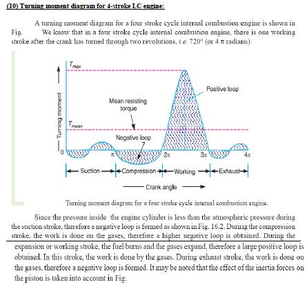
1 LECTURE-I UNIT I - Force Analysis (1) Introduction: If the acceleration of moving links in a mechanism is running with considerable amount of linear and/or angular accelerations, inertia forces are generated and these inertia forces also must be overcome by the driving motor as an addition to the forces exerted by the external load or work the mechanism does. (2) Newton s Law: First Law Everybody will persist in its state of rest or of uniform motion (constant velocity) in a straight line unless it is compelled to change that state by forces impressed on it. This means that in the absence of a non-zero net force, the center of mass of a body either is at rest or moves at a constant velocity. Second Law A body of mass m subject to a force F undergoes an acceleration a that has the same direction as the force and a magnitude that is directly proportional to the force and inversely proportional to the mass, i.e., F = ma. Alternatively, the total force applied on a body is equal to the time derivative of linear momentum of the body. Third Law The mutual forces of action and reaction between two bodies are equal, opposite and collinear. This means that whenever a first body exerts a force F on a second body, the second body exerts a force F on the first body. F and F are equal in magnitude and opposite in direction. This law is sometimes referred to as the action-reaction law, with F called the "action" and F the "reaction" (3) Types of force Analysis: Equilibrium of members with two forces Equilibrium of members with three forces Equilibrium of members with two forces and torque Equilibrium of members with two couples. Equilibrium of members with four forces. (4) Principle of Super Position: Sometimes the number of external forces and inertial forces acting on a mechanism are too much for graphical solution. In this case we apply the method of superposition. Using superposition the entire system is broken up into (n) problems, where n is the number of forces, by considering the external and inertial forces of each link individually. Response of a linear system to several forces acting simultaneously is equal to the sum of responses of the system to the forces individually. This approach is useful because it can be performed by graphically. (5) Free Body Diagram: A free body diagram is a pictorial representation often used by physicists and engineers to analyze the forces acting on a body of interest. A free body diagram shows all forces of all types acting on this body. Drawing such a diagram can aid in solving for the unknown forces or the equations of 1
2 motion of the body. Creating a free body diagram can make it easier to understand the forces, and torques or moments, in relation to one another and suggest the proper concepts to apply in order to find the solution to a problem. The diagrams are also used as a conceptual device to help identify the internal forces for example, shear forces and bending moments in beams which are developed within structures. (6) D Alemberts Principle: D'Alembert's principle, also known as the Lagrange d'alembert principle, is a statement of the fundamental classical laws of motion. It is named after its discoverer, the French physicist and mathematician Jean le Rond d'alembert. The principle states that the sum of the differences between the forces acting on a system and the time derivatives of the momenta of the system itself along any virtual displacement consistent with the constraints of the system is zero. (7) Dynamic Analysis of Four bar Mechanism: A four-bar linkage or simply a 4-bar or four-bar is the simplest movable linkage. It consists of four rigid bodies (called bars or links), each attached to two others by single joints or pivots to form closed loop. Four-bars are simple mechanisms common in mechanical engineering machine design and fall under the study of kinematics. Dynamic Analysis of Reciprocating engines. Inertia force and torque analysis by neglecting weight of connecting rod. Velocity and acceleration of piston. Angular velocity and Angular acceleration of connecting rod. Force and Torque Analysis in reciprocating engine neglecting the weight of connecting rod. Equivalent Dynamical System Determination of two masses of equivalent dynamical system (8) Turning Moment Diagram: The turning moment diagram is graphical representation of the turning moment or crank effort for various positions of crank. LECTURE-2 (9) Single cylinder double acting engine: 2
3 3

4 LECTURE-3 4
5 5

6 Lecture-4 6

7 LECTURE-5 7

8 LECTURE-6 8
9 9

10 LECTURE-7 10
11 LECTURE-8,9 & 10 11
12 12
13 UNIT II BALANCING (1) Introduction: Balancing is the process of eliminating or at least reducing the ground forces and/or moments. It is achieved by changing the location of the mass centres of links. Balancing of rotating parts is a well known problem. A rotating body with fixed rotation axis can be fully balanced i.e. all the inertia forces and moments. For mechanism containing links rotating about axis which are not fixed, force balancing is possible, moment balancing by itself may be possible, but both not possible. We generally try to do force balancing. A fully force balance is possible, but any action in force balancing severe the moment balancing. (2) Balancing of rotating masses: The process of providing the second mass in order to counteract the effect of the centrifugal force of the first mass is called balancing of rotating masses. (3) Static balancing: The net dynamic force acting on the shaft is equal to zero. This requires that the line of action of three centrifugal forces must be the same. In other words, the centre of the masses of the system must lie on the axis of the rotation. This is the condition for static balancing. (4) Dynamic balancing: The net couple due to dynamic forces acting on the shaft is equal to zero. The algebraic sum of the moments about any point in the plane must be zero. (5) Various cases of balancing of rotating masses: Balancing of a single rotating mass by single mass rotating in the same plane. Balancing of a single rotating mass by two masses rotating in the different plane. Balancing of a several masses rotating in single plane. Balancing of a several masses rotating in different planes. 13
14 14
15 15
16 16
17 17
18 18
19 19
20 20

21 21
22 22
23 (12) Balancing of single cylinder engine: A single cylinder engine produces three main vibrations. In describing them we will assume that the cylinder is vertical. Firstly, in an engine with no balancing counterweights, there would be an enormous 23
24 vibration produced by the change in momentum of the piston, gudgeon pin, connecting rod and crankshaft once every revolution. Nearly all single-cylinder crankshafts incorporate balancing weights to reduce this. While these weights can balance the crankshaft completely, they cannot completely balance the motion of the piston, for two reasons. The first reason is that the balancing weights have horizontal motion as well as vertical motion, so balancing the purely vertical motion of the piston by a crankshaft weight adds a horizontal vibration. The second reason is that, considering now the vertical motion only, the smaller piston end of the connecting rod (little end) is closer to the larger crankshaft end (big end) of the connecting rod in mid-stroke than it is at the top or bottom of the stroke, because of the connecting rod's angle. So during the 180 rotation from mid-stroke through top-dead-center and back to mid-stroke the minor contribution to the piston's up/down movement from the connecting rod's change of angle has the same direction as the major contribution to the piston's up/down movement from the up/down movement of the crank pin. By contrast, during the 180 rotation from mid-stroke through bottom-dead-center and back to mid-stroke the minor contribution to the piston's up/down movement from the connecting rod's change of angle has the opposite direction of the major contribution to the piston's up/down movement from the up/down movement of the crank pin. The piston therefore travels faster in the top half of the cylinder than it does in the bottom half, while the motion of the crankshaft weights is sinusoidal. The vertical motion of the piston is therefore not quite the same as that of the balancing weight, so they can't be made to cancel out completely. Secondly, there is a vibration produced by the change in speed and therefore kinetic energy of the piston. The crankshaft will tend to slow down as the piston speeds up and absorbs energy, and to speed up again as the piston gives up energy in slowing down at the top and bottom of the stroke. This vibration has twice the frequency of the first vibration, and absorbing it is one function of the flywheel. Thirdly, there is a vibration produced by the fact that the engine is only producing power during the power stroke. In a four-stroke engine this vibration will have half the frequency of the first vibration, as the cylinder fires once every two revolutions. In a two-stroke engine, it will have the same frequency as the first vibration. This vibration is also absorbed by the flywheel. (13) Balancing of inertial forces in the multi-cylinder engine: In multi-cylinder engines the mutual counteractions of the various components in the Crank shaft assembly are one of the essential factors determining the selection of the Crank shafts configuration and with it the design of the engine itself. The inertial forces are Balanced if the common centre of gravity for all moving crankshaft-assembly components lies at the crankshaft's midpoint, i.e. if the crankshaft is symmetrical (as viewed from the front). The crankshaft's symmetry level can be defined using geometrical representations of 1st- and 2nd-order forces (star diagrams). The 2nd order star diagram for the four-cylinder in-line engine is asymmetrical, meaning that this order is characterized by substantial free inertial Forces. These forces can be balanced using two countershafts rotating in opposite directions at double the rate of the crankshaft (Lanchester system). 24

25 (14) Partial balancing of Locomotives: 25
26 26
27 27
28 28
29 29
30 UNIT III FREE VIBRATIONS (1) Introduction: When a system is subjected to an initial disturbance and then left free to vibrate on its own, the resulting vibrations are referred to as free vibrations.free vibration occurs when a mechanical system is set off with an initial input and then allowed to vibrate freely. Examples of this type of vibration are pulling a child back on a swing and then letting go or hitting a tuning fork and letting it ring. The mechanical system will then vibrate at one or more of its "natural frequencies" and damp down to zero. (2) Basic elements of vibration system: Mass or Inertia Springiness or Restoring element Dissipative element (often called damper) External excitation (3) Causes of vibration: Unbalance: This is basically in reference to the rotating bodies. The uneven distribution of mass in a rotating body contributes to the unbalance. A good example of unbalance related vibration would be the vibrating alert in our mobile phones. Here a small amount of unbalanced weight is rotated by a motor causing the vibration which makes the mobile phone to vibrate. You would have experienced the same sort of vibration occurring in your front loaded washing machines that tend to vibrate during the spinning mode. Misalignment: This is an other major cause of vibration particularly in machines that are driven by motors or any other prime movers. Bent Shaft: A rotating shaft that is bent also produces the the vibrating effect since it losses it rotation capability about its center. Gears in the machine: The gears in the machine always tend to produce vibration, mainly due to their meshing. Though this may be controlled to some extent, any problem in the gearbox tends to get enhanced with ease. Bearings: Last but not the least, here is a major contributor for vibration. In majority of the cases every initial problem starts in the bearings and propagates to the rest of the members of the machine. A bearing devoid of lubrication tends to wear out fast and fails quickly, but before this is noticed it damages the remaining components in the machine and an initial look would seem as if something had gone wrong with the other components leading to the bearing failure. (4) Effects of vibration: 30

31 (a)bad Effects: The presence of vibration in any mechanical system produces unwanted noise, high stresses, poor reliability, wear and premature failure of parts. Vibrations are a great source of human discomfort in the form of physical and mental strains. (b)good Effects: A vibration does useful work in musical instruments, vibrating screens, shakers, relive pain in physiotherapy. (5) Methods of reduction of vibration: -unbalance is its main cause, so balancing of parts is necessary. -using shock absorbers. -using dynamic vibration absorbers. -providing the screens (if noise is to be reduced) (6) Types of vibratory motion: Free Vibration Forced Vibration (7) Terms used vibratory motion: (a)time period (or)period of vibration: It is the time taken by a vibrating body to repeat the motion itself.time period is usually expressed in seconds. (b) Cycle: It is the motion completed in one time period. (c) Periodic motion: A motion which repeats itself after equal interval of time. (d)amplitude (X) The maximum displacement of a vibrating body from the mean position.it is usually expressed in millimeter. (e) Frequency (f) The number of cycles completed in one second is called frequency (8) Degrees of freedom: The minimum number of independent coordinates required to specify the motion of a system at any instant is known as D.O.F of the system. (9) Single degree of freedom system: The system shown in this figure is what is known as a Single Degree of Freedom system. We use the term degree of freedom to refer to the number of coordinates that are required to specify completely the configuration of the system. Here, if the position of the mass of the system is specified then accordingly the position of the spring and damper are also identified. Thus we need just one coordinate (that of the mass) to specify the system completely and hence it is known as a single degree of freedom system. 31
32 (10) Two degree of freedom system: A two degree of freedom system With reference to automobile applications, this is referred as quarter car model. The bottom mass refers to mass of axle, wheel etc components which are below the suspension spring and the top mass refers to the mass of the portion of the car and passenger. Since we need to specify both the top and bottom mass positions to completely specify the system, this becomes a two degree of freedom system. (11) Types of Vibratory motion: 32

33 33
34 34
35 35
36 36
37 37
38 38
39 39
40 40
41 41
42 42
43 43
44 44
45 45
46 46
47 47
48 48
49 UNIT-IV FORCED VIBRATION Lecture-1 Forced Vibration: When the body vibrates under the influence of external force, then the body is said to be under forced vibration. Examples of forced vibration: 1. Ringing of electric bell. 2. Vibration of various machines like air compressor, IC engines, Machine tools and mobile cranes. Types of external Excitation: 1. Periodic forces, 2. Impulse type of forces, 3. Random Forces. Periodic forces are further classified into harmonic and non-harmonic forces. Vibration because of impulsive forces is called as transient. Earthquake and acoustic excitation are typical examples of random forces. In this chapter we would be analysing only about periodic forcing functions. Frequency of Under Damped Forced Vibrations Consider a system consisting of spring, mass and damper as shown in Fig. Let the system is acted upon by an external periodic (i.e. simple harmonic) disturbing force, Fx=F cos.t wheref = Static force, and = Angular velocity of the periodic disturbing force. 49
50 When the system is constrained to move in vertical guides, it has only one degree of freedom. Let at sometime t, the mass is displaced downwards through a distance x from its mean position. Important formulas to be remembered: When Damping is negligible, then c = 0 At resonance = n. Therefore the angular speed at which the resonance occurs is 50
. We have proved in the previous article that the maximum displacement or the amplitude of forced vibration, 51")
51 Lecture-2 Magnification Factor or Dynamic Magnifier It is the ratio of maximum displacement of the forced vibration (x max ) to the deflection due to the static force F(x o ). We have proved in the previous article that the maximum displacement or the amplitude of forced vibration, 51
52 The magnification factor or dynamic magnifier gives the factor by which the static deflection produced by a force F (i.e.x o ) must be multiplied in order to obtain the maximum amplitude of the forced vibration (i.e. x max) by the harmonic force Fcos.t 1. If there is no damping (i.e. if the vibration is undamped), then c = 0. In that case, magnification factor, 2. At resonance, = n. Therefore magnification factor, Problem-1 A single cylinder vertical petrol engine of total mass 300 kg is mounted upon a steel chassis frame and causes a vertical static deflection of 2 mm. The reciprocating parts of the engine have a mass of 20 kg and move through a vertical stroke of 150 mm with simple harmonic motion. A dashpot is provided whose damping resistance is directly proportional to the velocity and amounts to 1.5 kn per metre per second. Considering that the steady state of vibration is reached; determine: 1. the amplitude of forced vibrations, when the driving shaft of the engine rotates at 480 r.p.m, and 2. the speed of the driving shaft at which resonance will occur. Given: m = 300 kg; = 2 mm = m ;m1 = 20 kg ; l = 150 mm= 0.15 m ; c = 1.5 kn/m/s = 1500 N/m/s ; N = 480 r.p.m. or 2π 480 / 60 = 50.3 rad/s 52
53 Lecture-3 Problem 2 A mass of 10 kg is suspended from one end of a helical spring, the other end being fixed. The stiffness of the spring is 10 N/mm. The viscous damping causes the amplitude to decrease to one-tenth of the initial value in four complete oscillations. If a periodic force of 150 cos 50 t N is applied at the mass in the vertical direction, find the amplitude of the forced vibrations. What is its value of resonance? Given: m = 10 kg; s = 10 N/mm = N/m ; X 5 = X 1 / 10 53
54 Amplitude of the forced vibrations 54
55 Lecture-4 Problem 3 A single cylinder vertical petrol engine of total mass 300 kg is mounted upon a steel chassis frame and causes a vertical static deflection of 2 mm. under this load. Calculate the frequency of free vibrations and verify that a viscous damping force amounting to approximately 1000 N at a speed of 1 m/s is just-sufficient to make the motion aperiodic. If when damped to this extent, the body is subjected to a disturbing force with a maximum value of 125 N making 8 cycles/s, find the amplitude of the ultimate motion. Given: m = 20 kg; c = 1000 N/m/s; F = 125 N ;f = 8 cycles/s Frequency of free vibrations We know that frequency of free vibrations, The critical damping to make the motion aperiodic is such that damped frequency is zero, This means that the viscous damping force is 1023 N at a speed of 1 m/s. Therefore a viscous damping force amounting to approximately 1000 N at a speed of 1 m/s is just sufficient to make the motion aperiodic. Amplitude of ultimate motion We know that angular speed of forced vibration, 2π f 2π rad/s and stiffness of the spring, s = m.g/ δ= / = N/m Amplitude of ultimate motion i.e. maximum amplitude of forced vibration 55
56 Lecture-5 Problem-4 The time of free vibration of a mass hung from the end of a helical spring is 0.8 second. When the mass is stationary, the upper end is made to move upwards with a displacement y metre such that y = sin 2 t, where t is the time in seconds measured from the beginning of the motion. Neglecting the mass of the spring and any damping effects, determine the vertical distance through which the mass is moved in the first 0.3 second. Given :tp= 0.8 s ; y = sin 2 t Let m = Mass hung to the spring in kg, and s = Stiffness of the spring in N/m. We know that time period of free vibrations (tp), If x metres is the upward displacement of mass m from its equilibrium position after time t seconds, the equation of motion is given by 56
57 Lecture-6 Vibration Isolation and Transmissibility A little consideration will show that when an unbalanced machine is installed on the foundation, it produces vibration in the foundation. In order to prevent these vibrations or to minimise the transmission of forces to the foundation, the machines are mounted on springs and dampers or on some vibration isolating material, as shown in Fig. The arrangement is assumed to have one degree of freedom, i.e. it can move up and down only. It may be noted that when a periodic (i.e. simple harmonic) disturbing force F cos t is applied to a machine of mass m supported by a spring of stiffness s, then the force is transmitted by means of the spring and the damper or dashpot to the fixed support or foundation. The ratio of the force transmitted (FT) to the force applied (F) is known as the isolation factor or transmissibility ratio of the spring support. We have discussed above that the force transmitted to the foundation consists of the following two forces: 1. Spring force or elastic force which is equal to s. x max, and 2. Damping force which is equal to c..x max. Since these two forces are perpendicular to one another, as shown in Fig, therefore the force transmitted, 57
58 When the damper is not provided, then c = 0, and From above, we see that when / n 1, ϵ is negative. This means that there is a phase difference of 180 between the transmitted force and the disturbing force (F cos.t). The value of / n must be greater than 2 if ϵ is to be less than 1 and it is the numerical value of ϵ, independent of any phase difference between the forces that may exist which is important. It is therefore more convenient to use equation (ii) in the following form, i.e. Fig below is the graph for different values of damping factor c/cc to show the variation of transmissibility ratio (ϵ ) against the ratio / n. 1. When / n 2, then all the curves pass through the point ϵ = 1 for all values of damping factor c/c c. 58

59 2. When / n 2, then ϵ > 1 for all values of damping factor c/cc. This means that the force transmitted to the foundation through elastic support is greater than the force applied. 3. When / n 2, then ϵ < 1 for all values of damping factor c/cc. This shows thatthe force transmitted through elastic support is less than the applied force. Thus vibration isolationis possible only in the range of / n 2 We also see from the curves in Fig above that the damping is detrimental beyond / n 2 and advantageous only in the region / n < 2. It is thus concluded that for the vibration isolation, dampers need not to be provided but in order to limit resonance amplitude, stops may be provided. Lecture-7 Problem-5 The mass of an electric motor is 120 kg and it runs at 1500 r.p.m. The armature mass is 35 kg and its C.G. lies 0.5 mm from the axis of rotation. The motor is mounted on five springs of negligible damping so that the force transmitted is 59
60 one-eleventh of the impressed force. Assume that the mass of the motor is equally distributed among the five springs. Determine: 1. stiffness of each spring; 2. dynamic force transmitted to the base at the operating speed; and 3. natural frequency of the system. Given m1 = 120 kg; m2 = 35 kg; r = 0.5 mm = m; ϵ = 1 / 11; N = 1500 r.p.m. or = 2π 1500 / 60 = rad/s; 1. Stiffness of each spring Let s = Combined stiffness of the spring in N-m, and n = Natural circular frequency of vibration of the machine in rad/s. We know that transmissibility ratio (ϵ ), Problem-6 Lecture-8 60
61 A machine has a mass of 100 kg and unbalanced reciprocating parts of mass 2 kg which move through a vertical stroke of 80 mm with simple harmonic motion. The machine is mounted on four springs, symmetrically arranged with respect to centre of mass, in such a way that the machine has one degree of freedom and can undergo vertical displacements only. Neglecting damping, calculate the combined stiffness of the spring in order that the force transmitted to the foundation is 1 / 25 th of the applied force, when the speed of rotation of machine crank shaft is 1000 r.p.m. When the machine is actually supported on the springs, it is found that the damping reduces the amplitude of successive free vibrations by 25%. Fin: 1. the force transmitted to foundation at 1000 r.p.m., 2. the force transmitted to the foundation at resonance, and 3. the amplitude of theforced vibration of the machine at resonance. Given: m1 = 100 kg ;m2 = 2 kg ; l = 80 mm = 0.08 m ; ϵ = 1 / 25 ; N = 1000 r.p.m. or 2π 1000 / 60 = rad/s Combined stiffness of springs Let s = Combined stiffness of springs in N/m, and n = Natural circular frequency of vibration of the machine in rad/s. We know that transmissibility ratio (ϵ ), 1. Force transmitted to the foundation at 1000 r.p.m. Let FT = Force transmitted, and x 1 = Initial amplitude of vibration. Since the damping reduces the amplitude of successive free vibrations by 25%, therefore final amplitude of vibration, x x1 We know that damping coefficient or damping force per unit velocity, 61
62 c a X 2m = 188 N/m/s and critical damping coefficient, cc 2m. n = 4100 N/m/s Actual value of transmissibility ratio, 62
63 Problem 7 Lecture-9 A single-cylinder engine of total mass 200 kg is to be mounted on an elastic support which permits vibratory movement in vertical direction only. The mass of the piston is 3.5 kg and has a vertical reciprocating motion which may be assumed simple harmonic with a stroke of 150 mm. It is desired that the maximum vibratory force transmitted through the elastic support to the foundation shall be 600 N when the engine speed is 800 r.p.m. and less than this at all higher speeds. 1. Find the necessary stiffness of the elastic support, and the amplitude of vibration at 800 r.p.m., and 2. If the engine speed is reduced below 800 r.p.m. at what speed will the transmitted forceagain becomes 600 N? Given :m1 = 200 kg ; m2 = 3.5 kg ; l = 150 mm = 0.15 mm or r = l/2 = m ;FT = 600 N ; N = 800 r.p.m. or 2π 800 / 60 = 83.8 rad/s We know that the disturbing force at 800 r.p.m., F = Centrifugal force on the piston m2..r = 3.5 (83.8) = 1843 N 1. Stiffness of elastic support and amplitude of vibration Let s = Stiffness of elastic support in N/m, and xmax= Max.amplitude of vibration in metres. Since the max.vibratory force transmitted to the foundation is equal to the force on the elastic support neglecting damping), therefore Max.vibratory force transmitted to the foundation, FT = Force on the elastic support = Stiffness of elastic support Max.amplitude of vibration 63
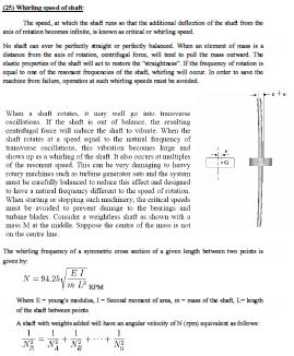
64 Lecture-10 Problem-8 A single cylinder vertical petrol engine of total mass 300 kg is mounted upon a steel chassis frame and causes a vertical static deflection of 2 mm. The reciprocating parts of the engine have a mass of 20 kg and move through a vertical stroke of 150 mm with simple harmonic motion. A dashpot is provided whose damping resistance is directly proportional to the velocity and amounts to 1.5 kn per metre per second. Considering that the steady state of vibration is reached; determine: 1. the amplitude of forced vibrations, when the driving shaft of the engine rotates at 480 r.p.m, and 2. the speed of the driving shaft at which resonance will occur. 64
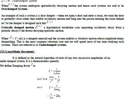
65 Given: m = 300 kg; = 2 mm = m ;m1 = 20 kg ; l = 150 mm= 0.15 m ; c = 1.5 kn/m/s = 1500 N/m/s ; N = 480 r.p.m. or 2π 480 / 60 = 50.3 rad/s Problem-9 Lecture-11 The mass of a single degree damped vibrating system is 7.5 kg and makes 24 free oscillations in 14 seconds when disturbed from its equilibrium position. The amplitude of vibration reduces to 0.25 of its initial value after five oscillations. Determine: 1. stiffness of the spring, 2. logarithmic decrement, and 3. damping factor, i.e. the ratio of the system damping to critical damping. Given: m = 7.5 kg Since 24 oscillations are made in 14 seconds, therefore frequency of free vibrations, fn= 24/14 = 1.7 and n 2π. fn 2π rad/s 65
66 Problem-10 Lecture-12 A machine of mass 75 kg is mounted on springs and is fitted with a dashpot to damp out vibrations. There are three springs each of stiffness 10 N/mm and it is found that the amplitude of vibration diminishes from 38.4 mm to 6.4 mm in two complete oscillations. Assuming that the damping force varies as the velocity, determin :1. the resistance of the dashpot at unit velocity ; 2. the ratio of the frequency of the damped vibration to the frequency of the undamped vibration ; and 3. the periodic time of the damped vibration. 66
67 Given: m = 75 kg ;s = 10 N/mm = N/m ; x1 = 38.4 mm = m ; x3 = 6.4 mm = m Since the stiffness of each spring is N/m and there are 3 springs, therefore total stiffness, s 3X10X X10 3 N/m We know that natural circular frequency of motion, 67
68 Types of Mechanisms for control are 1) Governors. 2) Gyroscope. Governors: UNIT-V MECHNISMS FOR CONTROL Lecture-1 The function of a governor is to regulate the mean speed of an engine, when there are variations in the load when the load on an engine increases, its speed decreases, therefore it becomes necessary to increase the supply of working fluid. On the other hand, when the load on the engine decreases, its speed increases and thus less working fluid is required. The governor automatically controls the supply of working fluid to the engine with the varying load conditions and keeps the mean speed within certain limits. 68
69 Difference between a Flywheel and Governor: The function of a flywheel in an engine is entirely different from that of a governor. It controls the speed variation caused by the fluctuations of the engine turning moment during each cycle of operation. It does not control the speed variations caused by a varying load. The varying demand for power is met by the governor regulating the supply of working fluid. Types of Governors The governors may, broadly, be classified as 1. Centrifugal governors 2. Inertia governors. Centrifugal governors: The centrifugal governors are based on the balancing of centrifugal force on the rotating ballsby an equal and opposite radial force, known as the controlling force.it consists of two balls ofequal mass, which are attached to the arms as shown in Fig. These balls are known as governorballs or fly balls. The balls revolve with a spindle, whichis driven by the engine through bevel gears. The upperends of the arms are pivoted to the spindle, so that theballs may rise up or fall down as they revolve about 69
70 thevertical axis. The arms are connected by the links to asleeve, which is keyed to the spindle. This sleeve revolveswith the spindle; but can slide up and down.the balls and the sleeve risewhen the spindle speedincreases, and falls when the speed decreases. In orderto limit the travel of the sleeve in upward and downwarddirections, two stops S, S are provided on thespindle. The sleeve isconnected by a bell crank leverto a throttle valve. The supply of the working fluid decreaseswhen the sleeve rises and increases when it falls. When the load on the engine increases, the engine and the governor speed decreases. This results in the decrease of centrifugal force on the balls. Hence the balls move inwards and the sleeve moves downwards. The downward movement of the sleeve operates a throttle valve at the other end of the bell crank lever to increase the supply of working fluid and thus the engine speed is increased. In this case, the extra power output is provided to balance the increased load. When the load on the engine decreases, the engine and the governor speed increases, which results in the increase of centrifugal force on the balls. Thus the balls move outwards and the sleeve rises upwards. This upward movement of the sleeve reduces the supply of the working fluid and hence the speed is decreased. In this case, the power output is reduced. Lecture-2 Terms Used in Governors 1. Height of a governor. It is the vertical distance from the centre of the ball to a point where the axes of the arms (or arms produced) intersect on the spindle axis. It is usually denoted by h. 2. Equilibrium speed. It is the speed at which the governor balls, arms etc., are in complete equilibrium and the sleeve does not tend to move upwards or downwards. 3. Mean equilibrium speed. It is the speed at the mean position of the balls or the sleeve. 4. Maximum and minimum equilibrium speeds. The speeds at the maximum and minimum radius of rotation of the balls, without tending to move either way are known as maximum and minimum equilibrium speeds respectively. Note : There can be many equilibrium speeds between the mean and the maximum and the mean and the minimum equilibrium speeds. 5. Sleeve lift. It is the vertical distance which the sleeve travels due to change in equilibrium speed. Watt Governor: The simplest form of a centrifugal governor is a Watt governor, as shown in Fig. It isbasically a conical pendulum with links attached to a sleeve of negligible mass. The arms of thegovernor may be connected to the spindle in the following three ways: 1. The pivot P may be on the spindle axis as shown in Fig. (a). 2. The pivot P may be offset from the spindle axis and the arms when produced intersect at O, as shown in Fig. (b). 3. The pivot P may be offset, but the arms cross the axis at O, as shown in Fig.(c). 70
71 m = Mass of the ball in kg, w = Weight of the ball in newtons = m.g, T = Tension in the arm in newtons, = Angular velocity of the arm and ball about the spindle axis in rad/s, r = Radius of the path of rotation of the ball i.e. horizontal distance from the centre of the ball to the spindle axis in metres, FC = Centrifugal force acting on the ball in newtons = m..r, and h = Height of the governor in metres. Problem-1 Calculate the vertical height of a Watt governor when it rotates at 60 r.p.m. Also find the change in vertical height when its speed increases to 61 r.p.m. Given: N1 = 60 r.p.m. ;N2 = 61 r.p.m. Initial height We know that initial height, Change in vertical height We know that final height, Change in vertical height = h1 h2 = = m = 8 mm Lecture-3 Porter Governor: The Porter governor is a modification of a Watt s governor, with central load attached to the sleeve as shown in Fig.(a). The load moves up and down the central spindle. This additional downward force increases the speed of revolution required to enable the balls to rise to any predetermined level. Consider the forces acting on one-half of the governor as shown in Fig.(b). 71
72 m = Mass of each ball in kg, w = Weight of each ball in newtons = m.g, M = Mass of the central load in kg, W = Weight of the central load in newtons = M.g, r = Radius of rotation in metres, h = Height of governor in metres, N = Speed of the balls in r.p.m. = Angular speed of the balls in rad/s = 2πN/60 rad/s, FC = Centrifugal force acting on the ball in newtons = m. 2.r, T1 = Force in the arm in newtons, T2 = Force in the link in newtons, α = Angle of inclination of the arm (or upper link) to the vertical, and = Angle of inclination of the link (or lower link) to the vertical. 1. When the length of arms are equal to the length of links and the points P and D lie on the same vertical line, then tanα = tan or q = tanα / tan = 1 2. When the loaded sleeve moves up and down the spindle, the frictional force acts on it in a direction opposite to that of the motion of sleeve. If F = Frictional force acting on the sleeve in newtons, then the equations (v) and (vi) may be written as The + sign is used when the sleeve moves upwards or the governor speed increases and negative sign is used when the sleeve moves downwards or the governor speed decreases. Problem 2 72
73 A Porter governor has equal arms each 250 mm long and pivoted on the axis of rotation. Each ball has a mass of 5 kg and the mass of the central load on the sleeve is 25 kg. Theradius of rotation of the ball is 150 mm when the governor begins to lift and 200 mm when the governor is at maximum speed. Find the minimum and maximum speeds and range of speed of the governor. (AU 2006) Gn :BP = BD = 250 mm = 0.25 m ; m = 5 kg ; M = 15 kg ; r1 = 150 mm = 0.15m; r 2 = 200 mm = 0.2 m Minimum speed when r 1 = BG = 0.15 m Let N1 = Minimum speed. From Fig(a), we find that height of the governor, h PG 0.2 m N1 = r.p.m. Maximum speed when r2 = BG = 0.2 m Let N2 = Maximum speed. From Fig(b), we find that height of the governor, N2 = r.p.m Range of speed We know that range of speed= N2 N1 = = 20.7 r.p.m. Lecture-4 Proell Governor 73
74 The Proell governor has the balls fixed at B and C to the extension of the links DF and EG, as shown in Fig (a). The arms FP and GQ are pivoted at P and Q respectively. Consider the equilibrium of the forces on one-half of the governor as shown in Fig (b). The instantaneous centre (I) lies on the intersection of the line PF produced and the line from D drawn perpendicular to the spindle axis. The perpendicular BM is drawn on ID. Problem 3 A governor of the Proell type has each arm 250 mm long. The pivots of the upper and lower arms are 25 mm from the axis. The central load acting on the sleeve has a mass of 25 kg and the each rotating ball has a mass of 3.2 kg. When the governor sleeve is in mid-position, the extension link of the lower arm is vertical and the radius of the path of rotation of the masses is175 mm. The vertical height of the governor is 200 mm.if the governor speed is 160 r.p.m. when in mid-position, find : 1. length of the extensionlink; and 2. tension in the upper arm. Given: PF = DF = 250 mm = 0.25 m ;PQ = DH = KG = 25 mm = m ; M = 25 kg ; m = 3.2 kg ; r = FG = 175 mm = m ; h = QG = PK = 200 mm = 0.2 m ; N = 160 r.p.m. 74
75 Length of the extension link BF = BM FM = = m = 108 mm Tension in the upper arm Problem 4 A Proell governor has equal arms of length 300 mm. The upper and lower ends of the arms are pivoted on the axis of the governor. The extension arms of the lower links are each 80 mm long and parallel to the axis when the radii of rotation of the balls are 150 mm and 200 mm. The mass of each ball is 10 kg and the mass of the central load is 100 kg. Determine the range of speed of thegovernor. 75

76 Lecture-5 Hartnell Governor A Hartnell governor is a spring loaded governor as shown in Fig It consists of two bell crank levers pivoted at the points O,O to the frame. The frame is attached to the governor spindle and therefore rotates with it. Each lever carries a ball at the end of the vertical arm OB and a roller at the end of the horizontal arm OR. A helical spring in compression provides equal downward forces on the two rollers through a collar on the sleeve. The spring force may be adjusted by screwing a nut up or down on the sleeve. Hartnell governor 76
77 Positions of Hartnell governor Minimum position: Maximum Position: Problem-5: In a spring loaded Hartnell type governor, the extreme radii of rotation of the balls are 80 mm and 120 mm. The ball arm and the sleeve arm of the bell crank lever are equal in length. The mass of each ball is 2 kg. If the speeds at the two extreme positions are 400 and 420 r.p.m., find : 1. the initial compression of the central spring, and 2. the spring constant. Given: r1 = 80 mm = 0.08 m ;r2 = 120 mm = 0.12 m ; x = y ; m = 2 kg ; N1 = 400r.p.m. or = 2 π 400/60 = 41.9 rad/s ; N2 = 420 r.p.m. or 2= 2 π 420/60 = 44 rad/s Initial compression of the central spring For Minimum Position: For Maximum Position 77
78 Lift of the sleeve Lecture-6 Problem-6: In a spring controlled governorof the type, as shown in Fig, the mass of each ball is1.5 kg and the mass of the sleeve is 8 kg. The two arms ofthe bell crank lever are at right angles and their lengthsare OB = 100 mm and OA = 40 mm. The distance ofthe fulcrum O of each bell crank lever from the axis ofrotation is 50 mm and minimum radius of rotation of thegovernor balls is also 50 mm. The correspondingequilibrium speed is 240 r.p.m. and the sleeve is requiredto lift 10 mm for an increase in speed of 5 per cent. Findthe stiffness and initial compression of the spring. Given: m = 1.5 kg; M = 8 kg; OB = x= 100 mm = 0.1 m; OA = y = 40 mm = 0.04 m; r = 50 mm = 0.05 m; r1 = 50 mm = 0.05 m; N1 = 240 r.p.m. or 1= 2π 240/60 = rad/s; h = 10 mm = 0.01 m; Increase in speed = 5% The spring controlled governor of the type, as shown in Fig, has the pivots for the bell crank lever on the moving sleeve. The spring is compressed between the sleeve and the cap which is fixed to the end of the governor shaft. The simplest way of analysing this type of governor is by taking moments about the instantaneous centre of all the forces which act on one of the bell crank levers. The minimum position of the governor is shown in Fig(a). 78
79 The maximum position of the governor is shown in Fig.(b). From the geometry of thefigure, 79
80 Hartung Governor A spring controlled governor of the Hartung type is shown in Fig (a). In this type of governor, the vertical arms of the bell crank levers are fitted with spring balls which compress against the frame of the governor when the rollers at the horizontal arm press against the sleeve. S = spring force, FC = Centrifugal force, M = Mass on the sleeve, and x and y = Lengths of the vertical and horizontal arm of the bell crank lever resp. 80
81 Lecture-7 Problem 6 In a spring-controlled governor of the Hartung type, the length of the ball and sleeve arms are 80 mm and 120 mm respectively. The total travel of the sleeve is 25 mm. In the mid position, each spring is compressed by 50 mm and the radius of rotation of the mass centres is 140 mm. Each ball has a mass of 4 kg and the spring has a stiffness of 10 kn/m of compression. The equivalent mass of the governor gear at the sleeve is 16 kg. Neglecting the moment due to the revolving masses when the arms are inclined, determine the ratio of the range of speed to the mean speed of the governor. Find, also, the speed in the mid-position. Given: x = 80 mm = 0.08 mm; y = 120 mm = 0.12 m ;h = 25 mm = m ; r = 140 mm = 0.14 m ; m = 4 kg ; s = 10 kn/m = N/m ; M = 16 kg ; Initial compression = 50 mm = 0.05 m Mean speed of the governor 81
82 Wilson-Hartnell Governor A Wilson-Hartnell governor is a governor in which the balls are connected by a spring in tension as shown in Fig. An auxiliary spring is attached to the sleeve mechanism through a lever by means of which the equilibrium speed for a given radius may be adjusted. The main spring may be considered of two equal parts each belonging to both the balls. The line diagram of a Wilson- Hartnell governor is shown in Fig. Sensitiveness of Governors Sensitiveness is defined as the ratio of the difference between the maximum and minimum equilibrium speeds to the mean equilibrium speed. Stability of Governors A governor is said to be stable when for every speed within the working range there is a definite configuration i.e. there is only one radius of rotation of the governor balls at which the governor is in equilibrium. For a stable governor, if the equilibrium speed increases, the radius of governor balls must also increase. Note: A governor is said to be unstable, if the radius of rotation decreases as the speed increases. Isochronous Governors 82
83 A governor is said to be isochronous when the equilibrium speed is constant (i.e. range of speed is zero) for all radii of rotation of the balls within the working range, neglecting friction. The isochronism is the stage of infinite sensitivity. Haunting A governor is said to be hunt if the speed of the engine fluctuates continuously above andbelow the mean speed. This is caused by a too sensitive governor which changes the fuel supplyby a large amount when a small change in the speed of rotation takes place. Effort and Power of a Governor The effort of a governor is the mean force exerted at the sleeve for a given percentage change of speed* (or lift of the sleeve). It may be noted that when the governor is running steadily, there is no force at the sleeve. But, when the speed changes, there is a resistance at the sleeve which opposes its motion. It is assumed that this resistance which is equal to the effort, varies uniformly from a maximum value to zero while the governor moves into its new position of equilibrium. The power of a governor is the work done at the sleeve for a given percentage change of speed. It is the product of the mean value of the effort and the distance through which the sleeve moves. Power = Mean effort lift of sleeve Lecture-8 Controlling force: Governor running at a steady speed, the inward force acting on the rotating balls is known as controlling force. It is equal and opposite to the centrifugal reaction. The Controlling force is given by Controlling force, FC = m. 2.r The controlling force is provided by the weight of the sleeve and balls as in Porter governor and by the spring and weight as in Hartnell governor (or spring controlled governor). When the graph between the controlling force (F C) as ordinate and radius of rotation of the balls (r) as abscissa is drawn, then the graph obtained is known as controlling force diagram. This diagram enables the stability and sensitiveness of the governor to be examined and also shows clearly the effect of friction. 83

84 Controlling Force Diagram for Porter Governor where Φis the angle between the axis of radius of rotation and a line joining a given point (say A) onthe curve to the origin O. Controlling Force Diagram for Spring-controlled Governors The controlling force diagram for the spring controlled governors is a straight line, as shownin Fig. We know that controlling force, F C = m. 2.r or FC /r = m. 2 For the governor to be stable, the controlling force (F C ) must increase as the radius of rotation(r) increases, i.e. F C / r must increase as r increases. Hence the controlling force line AB when produced must intersect the controlling force axis below the origin, as shown in Fig. The relation between the controlling force (F C ) 84
85 and the radius of rotation (r) for the stability of spring controlled governors is given by the following equation FC = a.r b (i) Where a and b are constants. The value of b in equation (i) may be made either zero or positive by increasing the initial tension of the spring. If b is zero, the controlling force line CD passes through the origin and the governor becomes isochronous because F C /r will remain constant for all radii of rotation. The relation between the controlling force and the radius of rotation, for an isochronous governor is, therefore, FC = a.r (ii) If b is greater than zero or positive, then F C /r decreases as r increases, so that the equilibrium speed of the governor decreases with an increase of the radius of rotation of balls, which is impracticable. Such a governor is said to be unstable and the relation between the controlling force and the radius of rotation is, therefore FC = a.r+ b (iii) Coefficient of Insensitiveness We have assumed the governor to be frictionless. In actual practice, there is always friction in the joints and operating mechanism of the governor. Since the frictional force always acts in the opposite direction to that of motion, therefore, when the speed of rotation decreases, the friction prevents the downward movement of the sleeve and the radial inward movement of the balls. On the other hand, when the speed of rotation increases, the friction prevents the upward movement of the sleeve and radial outward movement of the balls. 85
86 Lecture-9 Gyroscopic Couple: Consider a disc spinning with an angular velocity rad/s about the axis of spin OX, in anticlockwise direction when seen from the front, as shown in Fig(a). Since the plane in which the disc is rotating is parallel to the plane YOZ, therefore it is called plane of spinning. The planexoz is a horizontal plane and the axis of spin rotates in a plane parallel to the horizontal plane aboutan axis OY. In other words, the axis of spin is said to be rotating or processing about an axis OY. Inother words, the axis of spin is said to be rotating or processing about an axis OY (which is perpendicular to both the axes OX and OZ) at an angular velocity P rap/s. This horizontal plane XOZ is called plane of precession and OY is the axis of precession. I = Mass moment of inertia of the disc about OX, and = Angular velocity of the disc. Angular momentum of the disc= I. Since the angular momentum is a vector quantity, therefore it may be represented by the vector ox, as shown in Fig.(b). The axis of spin OX is also rotating anticlockwise when seen from the top about the axis OY. Let the axis OX is turned in the plane XOZ through a small angle δ radians to the position OX, in time δtseconds. Assuming the angular velocity to be constant, the angular momentum will now be represented by vector OX. Change in angular momentum = I..δ Rate of change of angular momentum 86
87 The rate of change of angular momentum will result by the application of a couple to the disc, therefore the couple applied to the disc causing precession Problem 7 A uniform disc of diameter 300 mm and of mass 5 kg is mounted on one end of an arm of length 600 mm. The other end of the arm is free to rotate in a universal bearing. If the disc rotates about the arm with a speed of 300 r.p.m. clockwise, looking from the front, with what speed will it precess about the vertical axis? Given: d = 300 mm or r = 150 mm = 0.15 m ;m = 5 kg ; l = 600 mm = 0.6 m ; N = 300 r.p.m. or π 300/60 = rad/s. I = m.r 2 /2 = 5(0.15) 2 /2 = kg-m 2 Lecture-10 Effect of the Gyroscopic Couple on an Aeroplane The top and front views of an aeroplane are shown in Fig (a). Let engine or propeller rotates in the clockwise direction when seen from the rear or tail end and the aeroplane takes a turn to the left. 87
88 Aeroplane taking left turn Notes: 1. when the aeroplane takes a right turn under similar conditions as discussed above, the effect of the reactive gyroscopic couple will be to dip the nose and raise the tail of the aeroplane. 2. When the engine or propeller rotates in anticlockwise direction when viewed from the rear or tail end and the aeroplane takes a left turn, then the effect of reactive gyroscopic couple will be to dip the nose and raise the tail of the aeroplane. 3. When the aeroplane takes a right turn under similar conditions as mentioned in note 2 above, theeffect of reactive gyroscopic couple will be to raise the nose and dip the tail of the aeroplane. 4. When the engine or propeller rotates in clockwise direction when viewed from the front and theaeroplane takes a left turn, then the effect of reactive gyroscopic couple will be to raise the tail and dip the noseof the aeroplane. 5. When the aeroplane takes a right turn under similar conditions as mentioned in note 4-above, theeffect of reactive gyroscopic couple will be to raise the nose and dip the tail of the aeroplane. Problem 8 An aeroplane makes a complete half circle of 50 metres radius, towards left, when flying at 200 km per hr. The rotary engine and the propeller of the plane has a mass of 400 kg and a radius of gyration of 0.3 m. The engine rotates at 2400 r.p.m. clockwise when viewed from the rear. Find the gyroscopic couple on the aircraft and state its effect on it. Given :R = 50 m ; v = 200 km/hr = 55.6 m/s ; m = 400 kg ; k = 0.3 m ; N = 2400 r.p.m. or = 2π 2400/60 = 251 rad/s We know that mass moment of inertia of the engine and the propeller, I = m.k 2 = 400(0.3) 2 = 36 kg-m 2 and angular velocity of precession, P= v/r= 55.6/50 = 1.11 rad/s We know that gyroscopic couple acting on the aircraft, 88
89 C = I. P= = N-m = kn-m When the aeroplane turns towards left, the effect of thegyroscopic couple is to lift the nose upwards and tail downwards. Terms Used in a Naval Ship The top and front views of a naval ship are shown in Fig. The fore end of the ship iscalled bow and the rear end is known as stern or aft. The left hand and right hand sides of the ship,when viewed from the stern are called port and star-board respectively. We shall now discuss theeffect of gyroscopic couple on the naval ship in the following three cases: 1. Steering, 2. Pitching and 3. Rolling. Lecture-11 Effect of Gyroscopic Couple on a Naval Ship during Steering Steering is the turning of a complete ship in a curve towards left or right, while it moves forward. Consider the ship taking a left turn, and rotor rotates in the clockwise direction when viewed from the stern, as shown in Fig. The effect of gyroscopic couple on a naval ship during steering taking left or right turn may be obtained in the similar way as for an aeroplane as discussed earlier. 89
90 Effect of Gyroscopic Couple on a Naval Ship during Pitching Effect of Gyroscopic Couple on a Naval Ship during Rolling We know that, for the effect of gyroscopic couple to occur, the axis of precession should always be perpendicular to the axis of spin. If, however, the axis of precession becomes parallel to the axis of spin, there will be no effect of the gyroscopic couple acting on the body of the ship. In case of rolling of a ship, the axis of precession (i.e. longitudinal axis) is always parallel to the axis of spin for all positions. Hence, there is no effect of the gyroscopic couple acting on the body of a ship. Problem 9 The turbine rotor of a ship has a mass of 8 tonnes and a radius of gyration 0.6 m. It rotates at 1800 r.p.m. clockwise, when looking from the stern. Determine the gyroscopic couple, if the ship travels at 100 km/hr and steer to the left in a curve of 75 m radius. Given: m = 8 t = 8000 kg; k = 0.6 m; N = 1800 r.p.m. or π 1800/60 = rad/s; v = 100 km/h = 27.8 m/s; R = 75 m Mass moment of inertia of the rotor, I = m.k 2 = 8000 (0.6) 2 = 2880 kg-m 2 Angular velocity of precession, P= v / R = 27.8 / 75 = 0.37 rad/s Gyroscopic couple, C = I. P= = N-m When the rotor rotates in clockwise direction when looking from the stern and the ship steers to the left, the effect of the reactive gyroscopic couple is to raise the bow and lower the stern. Problem 10 The turbine rotor of a ship has a mass of 3500 kg. It has a radius of gyration of 0.45 m and a speed of 3000 r.p.m. clockwise when looking from stern. Determine the gyroscopic couple and its effect upon the ship: 1. When the ship is steering to the left on a curve of 100 m radius at a speed of 36 km/h. 90
91 2. When the ship is pitching in a simple harmonic motion, the bow falling with its maximum velocity. The period of pitching is 40 seconds and the total angular displacement between the two extreme positions of pitching is 12 degrees. Given: m = 3500 kg; k = 0.45 m; N = 3000 r.p.m. or π 3000/60 = rad/s Lecture-12 Stability of a Four Wheel Drive Moving in a Curved Path 91

92 92
UNIT 6 GOVERNORS. 6.5 Controlling force and and stability of spring controlled Governors. Compiled By. Dr. B. Suresha, Professor
 UNIT 6 GOVERNORS STRUCTURE 6.1 Introduction 6.1.1 Objectives 6. Types of Governors 6..1 Porter Governor 6.. Hartnell Governor 6.3 Governor effort and Power 6.4 Characteristics of Governors 6.5 Controlling
Flywheels-Function need and Operation
 STUDY OF FLYWHEEL Flywheel definition A flywheel is an inertial energy-storage device. It absorbs mechanical energy and serves as a reservoir, storing energy during the period when the supply of energy
Balancing of Masses. 1. Balancing of a Single Rotating Mass By a Single Mass Rotating in the Same Plane
 lecture - 1 Balancing of Masses Theory of Machine Balancing of Masses A car assembly line. In this chapter we shall discuss the balancing of unbalanced forces caused by rotating masses, in order to minimize
UNIT 5 GOVERNORS 5.1 INTRODUCTION. Structure. 5.1 Introduction. 5.2 Classification of Governors 5.3 Gravity Controlled Centrifugal Governors
 UNIT 5 GVERNRS Governors Structure 5. Introduction bjectives 5. lassification of Governors 5.3 Gravity ontrolled entrifugal Governors 5.3. Watt Governor 5.3. Porter Governor 5.4 Spring ontrolled entrifugal
This equation of motion may be solved either by differential equation method or by graphical method as discussed below:
 2.15. Frequency of Under Damped Forced Vibrations Consider a system consisting of spring, mass and damper as shown in Fig. 22. Let the system is acted upon by an external periodic (i.e. simple harmonic)
DEPARTMENT OF MECHANICAL ENGINEERING Dynamics of Machinery. Submitted
 DEPARTMENT OF MECHANICAL ENGINEERING Dynamics of Machinery Submitted 1 UNIT I - Force Analysis INDEX (1) Introduction (2) Newton s Law (3) Types of force Analysis (4) Principle of Super Position (5) Free
Dynamics of Machinery
 Dynamics of Machinery Two Mark Questions & Answers Varun B Page 1 Force Analysis 1. Define inertia force. Inertia force is an imaginary force, which when acts upon a rigid body, brings it to an equilibrium
UNIT-I (FORCE ANALYSIS)
") DHANALAKSHMI SRINIVASAN INSTITUTE OF RESEACH AND TECHNOLOGY DEPARTMENT OF MECHANICAL ENGINEERING QUESTION BANK ME2302 DYNAMICS OF MACHINERY III YEAR/ V SEMESTER UNIT-I (FORCE ANALYSIS) PART-A (2 marks)
DHANALAKSHMI SRINIVASAN INSTITUTE OF RESEACH AND TECHNOLOGY DEPARTMENT OF MECHANICAL ENGINEERING QUESTION BANK ME2302 DYNAMICS OF MACHINERY III YEAR/ V SEMESTER UNIT-I (FORCE ANALYSIS) PART-A (2 marks)
Governors. Chapter : Governors l 653
 18 Chapter : Governors l 653 Features 1. Introduction.. Tpes of Governors. 3. Centrifugal Governors. 4. Terms Used in Governors. 5. Watt Governor. 6. Porter Governor. 7. Proell Governor. 8. Hartnell Governor.
ME2302 DYNAMICS OF MACHINERY
 ME2302 DYNAMICS OF MACHINERY TWO MARKS QUESTION AND ANSWERS 1. What are the conditions for a body to be in static and dynamic equilibrium? Necessary and sufficient conditions for static and dynamic equilibrium
LANMARK UNIVERSITY OMU-ARAN, KWARA STATE DEPARTMENT OF MECHANICAL ENGINEERING COURSE: MECHANICS OF MACHINE (MCE 322). LECTURER: ENGR.
. LECTURER: ENGR.") LANMARK UNIVERSITY OMU-ARAN, KWARA STATE DEPARTMENT OF MECHANICAL ENGINEERING COURSE: MECHANICS OF MACHINE (MCE 322). LECTURER: ENGR. IBIKUNLE ROTIMI ADEDAYO SIMPLE HARMONIC MOTION. Introduction Consider
LANMARK UNIVERSITY OMU-ARAN, KWARA STATE DEPARTMENT OF MECHANICAL ENGINEERING COURSE: MECHANICS OF MACHINE (MCE 322). LECTURER: ENGR. IBIKUNLE ROTIMI ADEDAYO SIMPLE HARMONIC MOTION. Introduction Consider
Department of Mechanical Engineering ME6505- DYNAMICS OF MACHINES. Two Marks Question and answer UNIT I FORCE ANALYSIS AND FLYWHEELS
 Department of Mechanical Engineering ME6505- DYNAMICS OF MACHINES Two Marks Question and answer UNIT I FORCE ANALYSIS AND FLYWHEELS 1. Distinguish between space diagram and free body diagram Space Diagram
UNIT 2 KINEMATICS OF LINKAGE MECHANISMS
 UNIT 2 KINEMATICS OF LINKAGE MECHANISMS ABSOLUTE AND RELATIVE VELOCITY An absolute velocity is the velocity of a point measured from a fixed point (normally the ground or anything rigidly attached to the
Varuvan Vadivelan. Institute of Technology LAB MANUAL. : 2013 : B.E. MECHANICAL ENGINEERING : III Year / V Semester. Regulation Branch Year & Semester
 Varuvan Vadivelan Institute of Technology Dharmapuri 636 703 LAB MANUAL Regulation Branch Year & Semester : 2013 : B.E. MECHANICAL ENGINEERING : III Year / V Semester ME 6511 - DYNAMICS LABORATORY GENERAL
LABORATORY MANUAL DYNAMICS OF MACHINE ME-314-E
 LABORATORY MANUAL DYNAMICS OF MACHINE ME-314-E 1 LIST OF EXPERIMENTS S. No. NAME OF EXPERIMENTS PAGE No. 1. To perform experiment on watt and Porter Governors to prepare performance characteristic Curves,
WORK SHEET FOR MEP311
 EXPERIMENT II-1A STUDY OF PRESSURE DISTRIBUTIONS IN LUBRICATING OIL FILMS USING MICHELL TILTING PAD APPARATUS OBJECTIVE To study generation of pressure profile along and across the thick fluid film (converging,
Engineering Science OUTCOME 2 - TUTORIAL 3 FREE VIBRATIONS
 Unit 2: Unit code: QCF Level: 4 Credit value: 5 Engineering Science L/60/404 OUTCOME 2 - TUTORIAL 3 FREE VIBRATIONS UNIT CONTENT OUTCOME 2 Be able to determine the behavioural characteristics of elements
= o + t = ot + ½ t 2 = o + 2
 Chapters 8-9 Rotational Kinematics and Dynamics Rotational motion Rotational motion refers to the motion of an object or system that spins about an axis. The axis of rotation is the line about which the
ME 6505 DYNAMICS OF MACHINES Fifth Semester Mechanical Engineering (Regulations 2013)
") ME 6505 DYNAMICS OF MACHINES Fifth Semester Mechanical Engineering (Regulations 2013) Unit II PART A 1. Define static balancing of shaft. (N/D 15) The net dynamic force acting on the shaft is equal to
ME 6505 DYNAMICS OF MACHINES Fifth Semester Mechanical Engineering (Regulations 2013) Unit II PART A 1. Define static balancing of shaft. (N/D 15) The net dynamic force acting on the shaft is equal to
The principle of the flywheel is found before the many centuries ago in spindle and the potter's wheel.
 TOM Fly Wheel Mechanical Engineering Department The principle of the flywheel is found before the many centuries ago in spindle and the potter's wheel. A heavy-rimmed rotating wheel used to minimize variations
T1 T e c h n i c a l S e c t i o n
 1.5 Principles of Noise Reduction A good vibration isolation system is reducing vibration transmission through structures and thus, radiation of these vibration into air, thereby reducing noise. There
 ME6511 DYNAMICS LABORATORY LIST OF EXPERIMENTS 1. Free Transverse Vibration I Determination of Natural Frequency 2. Cam Analysis Cam Profile and Jump-speed Characteristics 3. Free Transverse Vibration
UNIT 4 FLYWHEEL 4.1 INTRODUCTION 4.2 DYNAMICALLY EQUIVALENT SYSTEM. Structure. Objectives. 4.1 Introduction
 UNIT 4 FLYWHEEL Structure 4.1 Introduction Objectives 4. Dynamically Equivalent System 4.3 Turning Moment Diagram 4.3.1 Turning Moment Diagram of a Single Cylinder 4-storke IC Engine 4.3. Turning Moment
Advanced Higher Physics. Rotational motion
 Wallace Hall Academy Physics Department Advanced Higher Physics Rotational motion Problems AH Physics: Rotational Motion 1 2013 Data Common Physical Quantities QUANTITY SYMBOL VALUE Gravitational acceleration
TOPIC E: OSCILLATIONS EXAMPLES SPRING Q1. Find general solutions for the following differential equations:
 TOPIC E: OSCILLATIONS EXAMPLES SPRING 2019 Mathematics of Oscillating Systems Q1. Find general solutions for the following differential equations: Undamped Free Vibration Q2. A 4 g mass is suspended by
18.12 FORCED-DAMPED VIBRATIONS
 8. ORCED-DAMPED VIBRATIONS Vibrations A mass m is attached to a helical spring and is suspended from a fixed support as before. Damping is also provided in the system ith a dashpot (ig. 8.). Before the
Chapter 8 Acceleration in Mechanisms
 Chapter 8 Acceleration in Mechanisms 1 2 8.2. Acceleration Diagram for a Link Example 8.1 3 The crank of a slider crank mechanism rotates cw at a constant speed of 300 rpm. The crank is 150 mm & the ConRod
Kinematics of. Motion. 8 l Theory of Machines
 8 l Theory of Machines Features 1. 1ntroduction.. Plane Motion. 3. Rectilinear Motion. 4. Curvilinear Motion. 5. Linear Displacement. 6. Linear Velocity. 7. Linear Acceleration. 8. Equations of Linear
SCHEME OF BE 100 ENGINEERING MECHANICS DEC 2015
 Part A Qn. No SCHEME OF BE 100 ENGINEERING MECHANICS DEC 201 Module No BE100 ENGINEERING MECHANICS Answer ALL Questions 1 1 Theorem of three forces states that three non-parallel forces can be in equilibrium
STRUCTURAL DYNAMICS BASICS:
 BASICS: STRUCTURAL DYNAMICS Real-life structures are subjected to loads which vary with time Except self weight of the structure, all other loads vary with time In many cases, this variation of the load
Physics. Student Materials Advanced Higher. Tutorial Problems Mechanics HIGHER STILL. Spring 2000
 Spring 2000 HIGHER STILL Physics Student Materials Advanced Higher Tutorial Problems Mechanics TUTORIAL 1 You will find tutorials on each topic. The fully worked out answers are available. The idea is
[You will experience the effect of a centrifugal force if you swing a mass on the end of a piece of string around in a circle.]
![[You will experience the effect of a centrifugal force if you swing a mass on the end of a piece of string around in a circle.]](/thumbs/85/92293367.jpg "[You will experience the effect of a centrifugal force if you swing a mass on the end of a piece of string around in a circle.]") Balancing Rotating Masses The balancing of rotating bodies is important to avoid the damaging effects of vibration. Vibrations are noisy and uncomfortable. For example, when a car wheel is out of balance,
Balancing Rotating Masses The balancing of rotating bodies is important to avoid the damaging effects of vibration. Vibrations are noisy and uncomfortable. For example, when a car wheel is out of balance,
1. Replace the given system of forces acting on a body as shown in figure 1 by a single force and couple acting at the point A.
 Code No: Z0321 / R07 Set No. 1 I B.Tech - Regular Examinations, June 2009 CLASSICAL MECHANICS ( Common to Mechanical Engineering, Chemical Engineering, Mechatronics, Production Engineering and Automobile
INSTITUTE OF AERONAUTICAL ENGINEERING (Autonomous) Dundigal, Hyderabad
 Dundigal, Hyderabad") INSTITUTE OF AERONAUTICAL ENGINEERING (Autonomous) Dundigal, Hyderabad - 500 043 AERONAUTICAL ENGINEERING DEFINITIONS AND TERMINOLOGY Course Name : ENGINEERING MECHANICS Course Code : AAEB01 Program :
INSTITUTE OF AERONAUTICAL ENGINEERING (Autonomous) Dundigal, Hyderabad - 500 043 AERONAUTICAL ENGINEERING DEFINITIONS AND TERMINOLOGY Course Name : ENGINEERING MECHANICS Course Code : AAEB01 Program :
TOPIC : 8 : Balancing
 TOPIC : 8 : Balancing --------------------------------------------------------------- Q.1. What is balancing? What are its objectives? What are types of balancing? BALANCING: Balancing is the technique
LAB MANNUAL DYNAMICS OF MACHINE
 LAB MANNUAL OF DYNAMICS OF MACHINE (ME- 314-E) DEPTT. OF MECHANICAL ENGINEERING OM INSTITUTE OF TECHNOLOGY & MANAGEMENT 12km Stone, NH-65, Chandigarh Road Juglan (Hisar) Web Site-www.oitmhisar.com, Email:-
Name: Fall 2014 CLOSED BOOK
 Name: Fall 2014 1. Rod AB with weight W = 40 lb is pinned at A to a vertical axle which rotates with constant angular velocity ω =15 rad/s. The rod position is maintained by a horizontal wire BC. Determine
Engineering Mechanics Prof. U. S. Dixit Department of Mechanical Engineering Indian Institute of Technology, Guwahati Introduction to vibration
 Engineering Mechanics Prof. U. S. Dixit Department of Mechanical Engineering Indian Institute of Technology, Guwahati Introduction to vibration Module 15 Lecture 38 Vibration of Rigid Bodies Part-1 Today,
WEEKS 8-9 Dynamics of Machinery
 WEEKS 8-9 Dynamics of Machinery References Theory of Machines and Mechanisms, J.J.Uicker, G.R.Pennock ve J.E. Shigley, 2011 Mechanical Vibrations, Singiresu S. Rao, 2010 Mechanical Vibrations: Theory and
(1) (3)
 (3)") 1. This question is about momentum, energy and power. (a) In his Principia Mathematica Newton expressed his third law of motion as to every action there is always opposed an equal reaction. State what
1. This question is about momentum, energy and power. (a) In his Principia Mathematica Newton expressed his third law of motion as to every action there is always opposed an equal reaction. State what
Textbook Reference: Wilson, Buffa, Lou: Chapter 8 Glencoe Physics: Chapter 8
 AP Physics Rotational Motion Introduction: Which moves with greater speed on a merry-go-round - a horse near the center or one near the outside? Your answer probably depends on whether you are considering
Gyroscopic Couple and Precessional Motion
 480 l Theory of Machines 14 Fea eatur tures es 1. Introduction.. Precessional Angular Motion. 3. Gyroscopic Couple. 4. Effect of Gyroscopic Couple on an Aeroplane. 5. Terms Used in a Naval Ship. 6. Effect
End-of-Chapter Exercises
 End-of-Chapter Exercises Exercises 1 12 are conceptual questions that are designed to see if you have understood the main concepts of the chapter. 1. Figure 11.21 shows four different cases involving a
Dept of ECE, SCMS Cochin
 B B2B109 Pages: 3 Reg. No. Name: APJ ABDUL KALAM TECHNOLOGICAL UNIVERSITY SECOND SEMESTER B.TECH DEGREE EXAMINATION, MAY 2017 Course Code: BE 100 Course Name: ENGINEERING MECHANICS Max. Marks: 100 Duration:
Cams. 774 l Theory of Machines
 774 l Theory of Machines 0 Fea eatur tures es 1. Introduction.. Classification of Followers. 3. Classification of Cams. 4. Terms used in Radial cams. 5. Motion of the Follower. 6. Displacement, Velocity
Chapter 14 Oscillations. Copyright 2009 Pearson Education, Inc.
 Chapter 14 Oscillations Oscillations of a Spring Simple Harmonic Motion Energy in the Simple Harmonic Oscillator Simple Harmonic Motion Related to Uniform Circular Motion The Simple Pendulum The Physical
Rotational Kinematics and Dynamics. UCVTS AIT Physics
 Rotational Kinematics and Dynamics UCVTS AIT Physics Angular Position Axis of rotation is the center of the disc Choose a fixed reference line Point P is at a fixed distance r from the origin Angular Position,
VALLIAMMAI ENGINEERING COLLEGE SRM NAGAR, KATTANKULATHUR DEPARTMENT OF MECHANICAL ENGINEERING
 VALLIAMMAI ENGINEERING COLLEGE SRM NAGAR, KATTANKULATHUR 603203 DEPARTMENT OF MECHANICAL ENGINEERING BRANCH: MECHANICAL YEAR / SEMESTER: I / II UNIT 1 PART- A 1. State Newton's three laws of motion? 2.
Introduction to Mechanical Vibration
 2103433 Introduction to Mechanical Vibration Nopdanai Ajavakom (NAV) 1 Course Topics Introduction to Vibration What is vibration? Basic concepts of vibration Modeling Linearization Single-Degree-of-Freedom
A-level Physics (7407/7408)
") A-level Physics (7407/7408) Further Mechanics Test Name: Class: Date: September 2016 Time: 55 Marks: 47 Page 1 Q1.The diagram shows a strobe photograph of a mark on a trolley X, moving from right to left,
A-level Physics (7407/7408) Further Mechanics Test Name: Class: Date: September 2016 Time: 55 Marks: 47 Page 1 Q1.The diagram shows a strobe photograph of a mark on a trolley X, moving from right to left,
Chapter a. Spring constant, k : The change in the force per unit length change of the spring. b. Coefficient of subgrade reaction, k:
 Principles of Soil Dynamics 3rd Edition Das SOLUTIONS MANUAL Full clear download (no formatting errors) at: https://testbankreal.com/download/principles-soil-dynamics-3rd-editiondas-solutions-manual/ Chapter
The University of Melbourne Engineering Mechanics
 The University of Melbourne 436-291 Engineering Mechanics Tutorial Eleven Instantaneous Centre and General Motion Part A (Introductory) 1. (Problem 5/93 from Meriam and Kraige - Dynamics) For the instant
Chapter 8. Rotational Equilibrium and Rotational Dynamics. 1. Torque. 2. Torque and Equilibrium. 3. Center of Mass and Center of Gravity
 Chapter 8 Rotational Equilibrium and Rotational Dynamics 1. Torque 2. Torque and Equilibrium 3. Center of Mass and Center of Gravity 4. Torque and angular acceleration 5. Rotational Kinetic energy 6. Angular
Big Idea 4: Interactions between systems can result in changes in those systems. Essential Knowledge 4.D.1: Torque, angular velocity, angular
 Unit 7: Rotational Motion (angular kinematics, dynamics, momentum & energy) Name: Big Idea 3: The interactions of an object with other objects can be described by forces. Essential Knowledge 3.F.1: Only
(Refer Slide Time: 1: 19)
") Mechanical Measurements and Metrology Prof. S. P. Venkateshan Department of Mechanical Engineering Indian Institute of Technology, Madras Module - 4 Lecture - 46 Force Measurement So this will be lecture
Mechanical Measurements and Metrology Prof. S. P. Venkateshan Department of Mechanical Engineering Indian Institute of Technology, Madras Module - 4 Lecture - 46 Force Measurement So this will be lecture
NAME. (2) Choose the graph below that represents the velocity vs. time for constant, nonzero acceleration in one dimension.
 Choose the graph below that represents the velocity vs. time for constant, nonzero acceleration in one dimension.") (1) The figure shows a lever (which is a uniform bar, length d and mass M), hinged at the bottom and supported steadily by a rope. The rope is attached a distance d/4 from the hinge. The two angles are
(1) The figure shows a lever (which is a uniform bar, length d and mass M), hinged at the bottom and supported steadily by a rope. The rope is attached a distance d/4 from the hinge. The two angles are
Balancing of Rotating Masses
 Balancing of Rotating Masses 1 Balancing of Rotating Masses m Consider first a single mass m moving in a circular arc of radius r with an angular velocity rad/s. The mass has a centripetal (centre 2 seeking)
AP PHYSICS 1 Learning Objectives Arranged Topically
 AP PHYSICS 1 Learning Objectives Arranged Topically with o Big Ideas o Enduring Understandings o Essential Knowledges o Learning Objectives o Science Practices o Correlation to Knight Textbook Chapters
11. (7 points: Choose up to 3 answers) What is the tension,!, in the string? a.! = 0.10 N b.! = 0.21 N c.! = 0.29 N d.! = N e.! = 0.
 What is the tension,!, in the string? a.! = 0.10 N b.! = 0.21 N c.! = 0.29 N d.! = N e.! = 0.") A harmonic wave propagates horizontally along a taut string of length! = 8.0 m and mass! = 0.23 kg. The vertical displacement of the string along its length is given by!!,! = 0.1!m cos 1.5!!! +!0.8!!,
A harmonic wave propagates horizontally along a taut string of length! = 8.0 m and mass! = 0.23 kg. The vertical displacement of the string along its length is given by!!,! = 0.1!m cos 1.5!!! +!0.8!!,
Lectures Chapter 10 (Cutnell & Johnson, Physics 7 th edition)
") PH 201-4A spring 2007 Simple Harmonic Motion Lectures 24-25 Chapter 10 (Cutnell & Johnson, Physics 7 th edition) 1 The Ideal Spring Springs are objects that exhibit elastic behavior. It will return back
PH 201-4A spring 2007 Simple Harmonic Motion Lectures 24-25 Chapter 10 (Cutnell & Johnson, Physics 7 th edition) 1 The Ideal Spring Springs are objects that exhibit elastic behavior. It will return back
Chapter 4 Statics and dynamics of rigid bodies
 Chapter 4 Statics and dynamics of rigid bodies Bachelor Program in AUTOMATION ENGINEERING Prof. Rong-yong Zhao (zhaorongyong@tongji.edu.cn) First Semester,2014-2015 Content of chapter 4 4.1 Static equilibrium
Chapter 14. Oscillations. Oscillations Introductory Terminology Simple Harmonic Motion:
 Chapter 14 Oscillations Oscillations Introductory Terminology Simple Harmonic Motion: Kinematics Energy Examples of Simple Harmonic Oscillators Damped and Forced Oscillations. Resonance. Periodic Motion
Webreview Torque and Rotation Practice Test
 Please do not write on test. ID A Webreview - 8.2 Torque and Rotation Practice Test Multiple Choice Identify the choice that best completes the statement or answers the question. 1. A 0.30-m-radius automobile
Mechatronics. MANE 4490 Fall 2002 Assignment # 1
 Mechatronics MANE 4490 Fall 2002 Assignment # 1 1. For each of the physical models shown in Figure 1, derive the mathematical model (equation of motion). All displacements are measured from the static
Periodic Motion. Periodic motion is motion of an object that. regularly repeats
 Periodic Motion Periodic motion is motion of an object that regularly repeats The object returns to a given position after a fixed time interval A special kind of periodic motion occurs in mechanical systems
PLANAR RIGID BODY MOTION: TRANSLATION &
 PLANAR RIGID BODY MOTION: TRANSLATION & Today s Objectives : ROTATION Students will be able to: 1. Analyze the kinematics of a rigid body undergoing planar translation or rotation about a fixed axis. In-Class
Levers. 558 A Textbook of Machine Design
 558 A Textbook of Machine Design C H A P T E R 15 Levers 1. Introduction.. Application of Levers in Engineering Practice.. Design of a Lever. 4. Hand Lever. 5. Foot Lever. 6. Cranked Lever. 7. Lever for
Dynamics Plane kinematics of rigid bodies Section 4: TJW Rotation: Example 1
 Section 4: TJW Rotation: Example 1 The pinion A of the hoist motor drives gear B, which is attached to the hoisting drum. The load L is lifted from its rest position and acquires an upward velocity of
Dynamics of Machines. Prof. Amitabha Ghosh. Department of Mechanical Engineering. Indian Institute of Technology, Kanpur. Module No.
 Dynamics of Machines Prof. Amitabha Ghosh Department of Mechanical Engineering Indian Institute of Technology, Kanpur Module No. # 07 Lecture No. # 01 In our previous lectures, you have noticed that we
DYNAMICS ME HOMEWORK PROBLEM SETS
 DYNAMICS ME 34010 HOMEWORK PROBLEM SETS Mahmoud M. Safadi 1, M.B. Rubin 2 1 safadi@technion.ac.il, 2 mbrubin@technion.ac.il Faculty of Mechanical Engineering Technion Israel Institute of Technology Spring
Raymond A. Serway Chris Vuille. Chapter Thirteen. Vibrations and Waves
 Raymond A. Serway Chris Vuille Chapter Thirteen Vibrations and Waves Periodic Motion and Waves Periodic motion is one of the most important kinds of physical behavior Will include a closer look at Hooke
Chapter 15. Oscillatory Motion
 Chapter 15 Oscillatory Motion Part 2 Oscillations and Mechanical Waves Periodic motion is the repeating motion of an object in which it continues to return to a given position after a fixed time interval.
AP Physics QUIZ Chapters 10
 Name: 1. Torque is the rotational analogue of (A) Kinetic Energy (B) Linear Momentum (C) Acceleration (D) Force (E) Mass A 5-kilogram sphere is connected to a 10-kilogram sphere by a rigid rod of negligible
Name: Date: Period: AP Physics C Rotational Motion HO19
 1.) A wheel turns with constant acceleration 0.450 rad/s 2. (9-9) Rotational Motion H19 How much time does it take to reach an angular velocity of 8.00 rad/s, starting from rest? Through how many revolutions
Name Date Period PROBLEM SET: ROTATIONAL DYNAMICS
 Accelerated Physics Rotational Dynamics Problem Set Page 1 of 5 Name Date Period PROBLEM SET: ROTATIONAL DYNAMICS Directions: Show all work on a separate piece of paper. Box your final answer. Don t forget
4.0 m s 2. 2 A submarine descends vertically at constant velocity. The three forces acting on the submarine are viscous drag, upthrust and weight.
 1 1 wooden block of mass 0.60 kg is on a rough horizontal surface. force of 12 N is applied to the block and it accelerates at 4.0 m s 2. wooden block 4.0 m s 2 12 N hat is the magnitude of the frictional
Rotation. PHYS 101 Previous Exam Problems CHAPTER
 PHYS 101 Previous Exam Problems CHAPTER 10 Rotation Rotational kinematics Rotational inertia (moment of inertia) Kinetic energy Torque Newton s 2 nd law Work, power & energy conservation 1. Assume that
Lecture 6 mechanical system modeling equivalent mass gears
 M2794.25 Mechanical System Analysis 기계시스템해석 lecture 6,7,8 Dongjun Lee ( 이동준 ) Department of Mechanical & Aerospace Engineering Seoul National University Dongjun Lee Lecture 6 mechanical system modeling
10/23/2015. Chapter 7. Velocity in Mechanisms. (Relative Velocity Method) Mohammad Suliman Abuhaiba, Ph.D., PE
 Mohammad Suliman Abuhaiba, Ph.D., PE") Chapter 7 Velocity in Mechanisms (Relative Velocity Method) 1 2 7.2. Relative Velocity of Two Bodies Moving in Straight Lines 3 7.3. Motion of a Link Velocity of any point on a link wrt another point on
Chapter 7 Velocity in Mechanisms (Relative Velocity Method) 1 2 7.2. Relative Velocity of Two Bodies Moving in Straight Lines 3 7.3. Motion of a Link Velocity of any point on a link wrt another point on
PHYSICS 221, FALL 2011 EXAM #2 SOLUTIONS WEDNESDAY, NOVEMBER 2, 2011
 PHYSICS 1, FALL 011 EXAM SOLUTIONS WEDNESDAY, NOVEMBER, 011 Note: The unit vectors in the +x, +y, and +z directions of a right-handed Cartesian coordinate system are î, ĵ, and ˆk, respectively. In this
Code No: R Set No. 1
 Code No: R05010302 Set No. 1 I B.Tech Supplimentary Examinations, February 2008 ENGINEERING MECHANICS ( Common to Mechanical Engineering, Mechatronics, Metallurgy & Material Technology, Production Engineering,
SILVER OAK COLLEGE OF ENGINEERING & TECHNOLOGY
 BE - SEMESTER VI MID SEMESTER EXAMINATION SUMMER 2015 SUBJECT: DYNAMICS OF MACHINERY (161901) DATE: 09-03-2015 TIME: 02:00 pm to 03:13 pm TOTAL MARKS: 30 Q.1 (a) Define the following terms in short: (i)
Wheel and Axle. Author: Joseph Harrison. Research Ans Aerospace Engineering 1 Expert, Monash University
 Wheel and Axle Author: Joseph Harrison British Middle-East Center for studies & Research info@bmcsr.com http:// bmcsr.com Research Ans Aerospace Engineering 1 Expert, Monash University Introduction A solid
Kinematics, Dynamics, and Vibrations FE Review Session. Dr. David Herrin March 27, 2012
 Kinematics, Dynamics, and Vibrations FE Review Session Dr. David Herrin March 7, 0 Example A 0 g ball is released vertically from a height of 0 m. The ball strikes a horizontal surface and bounces back.
Chapter 8 Lecture. Pearson Physics. Rotational Motion and Equilibrium. Prepared by Chris Chiaverina Pearson Education, Inc.
 Chapter 8 Lecture Pearson Physics Rotational Motion and Equilibrium Prepared by Chris Chiaverina Chapter Contents Describing Angular Motion Rolling Motion and the Moment of Inertia Torque Static Equilibrium
TOPIC E: OSCILLATIONS SPRING 2019
 TOPIC E: OSCILLATIONS SPRING 2019 1. Introduction 1.1 Overview 1.2 Degrees of freedom 1.3 Simple harmonic motion 2. Undamped free oscillation 2.1 Generalised mass-spring system: simple harmonic motion
3. Kinetics of Particles
 3. Kinetics of Particles 3.1 Force, Mass and Acceleration 3.3 Impulse and Momentum 3.4 Impact 1 3.1 Force, Mass and Acceleration We draw two important conclusions from the results of the experiments. First,
The... of a particle is defined as its change in position in some time interval.
 Distance is the. of a path followed by a particle. Distance is a quantity. The... of a particle is defined as its change in position in some time interval. Displacement is a.. quantity. The... of a particle
DYNAMICS OF MACHINERY
 DYNAMICS OF MACHINERY B.TECH. DEGREE COURSE SCHEME AND SYLLABUS (00-03 ADMISSION ONWARDS) MAHATMA GANDHI UNIVERSITY KOTTAYAM, KERALA DYNAMICS OF MACHINERY Module 1 Balancing: - Balancing of rotating masses,
PSI AP Physics I Rotational Motion
 PSI AP Physics I Rotational Motion Multiple-Choice questions 1. Which of the following is the unit for angular displacement? A. meters B. seconds C. radians D. radians per second 2. An object moves from
Q.1 a) any six of the following 6x2= 12. i) Define - ( Each term 01 mark)
 any six of the following 6x2= 12. i) Define - ( Each term 01 mark)") Important Instructions to examiners: 1) The answers should be examined by key words and not as word-to-word as given in the model answer scheme. 2) The model answer and the answer written by candidate
Important Instructions to examiners: 1) The answers should be examined by key words and not as word-to-word as given in the model answer scheme. 2) The model answer and the answer written by candidate
PSI AP Physics I Rotational Motion
 PSI AP Physics I Rotational Motion Multiple-Choice questions 1. Which of the following is the unit for angular displacement? A. meters B. seconds C. radians D. radians per second 2. An object moves from
Inertia Forces in Reciprocating. Parts. 514 l Theory of Machines
 514 l Theory of Machines 15 Features 1. Introduction.. Resultant Effect of a System of Forces Acting on a Rigid Body. 3. D-Alembert s Principle. 4. Velocity and Acceleration of the Reciprocating Parts
Problem Solving Circular Motion Dynamics Challenge Problems
 Problem 1: Double Star System Problem Solving Circular Motion Dynamics Challenge Problems Consider a double star system under the influence of gravitational force between the stars. Star 1 has mass m 1
EDEXCEL NATIONAL CERTIFICATE/DIPLOMA ADVANCED MECHANICAL PRINCIPLES AND APPLICATIONS UNIT 18 NQF LEVEL 3
 EDEXCEL NATIONAL CERTIFICATE/DIPLOMA ADVANCED MECHANICAL PRINCIPLES AND APPLICATIONS UNIT 18 NQF LEVEL 3 OUTCOME 3 BE ABLE TO DETERMINE RELATIVE AND RESULTANT VELOCITY IN ENGINEERING SYSTEMS Resultant
Oscillatory Motion SHM
 Chapter 15 Oscillatory Motion SHM Dr. Armen Kocharian Periodic Motion Periodic motion is motion of an object that regularly repeats The object returns to a given position after a fixed time interval A
Practice. Newton s 3 Laws of Motion. Recall. Forces a push or pull acting on an object; a vector quantity measured in Newtons (kg m/s²)
") Practice A car starts from rest and travels upwards along a straight road inclined at an angle of 5 from the horizontal. The length of the road is 450 m and the mass of the car is 800 kg. The speed of
Practice A car starts from rest and travels upwards along a straight road inclined at an angle of 5 from the horizontal. The length of the road is 450 m and the mass of the car is 800 kg. The speed of
Chapter 9-10 Test Review
 Chapter 9-10 Test Review Chapter Summary 9.2. The Second Condition for Equilibrium Explain torque and the factors on which it depends. Describe the role of torque in rotational mechanics. 10.1. Angular
Class XI Chapter 7- System of Particles and Rotational Motion Physics
 Page 178 Question 7.1: Give the location of the centre of mass of a (i) sphere, (ii) cylinder, (iii) ring, and (iv) cube, each of uniform mass density. Does the centre of mass of a body necessarily lie
It will be most difficult for the ant to adhere to the wheel as it revolves past which of the four points? A) I B) II C) III D) IV
 I B) II C) III D) IV") AP Physics 1 Lesson 16 Homework Newton s First and Second Law of Rotational Motion Outcomes Define rotational inertia, torque, and center of gravity. State and explain Newton s first Law of Motion as it
AP Physics 1 Lesson 16 Homework Newton s First and Second Law of Rotational Motion Outcomes Define rotational inertia, torque, and center of gravity. State and explain Newton s first Law of Motion as it