Design of Heat Transfer Equipment
|
|
|
- Branden Booker
- 5 years ago
- Views:
Transcription
1 Design of Heat Transfer Equipment
2 Types of heat transfer equipment Type service Double pipe exchanger Heating and cooling Shell and tube exchanger All applications Plate heat exchanger Plate-fin exchanger Heating and cooling Spiral heat exchanger Air cooled Cooler and condensers Direct contact Cooling and quenching Agitated vessel Heating and cooling Fired heaters Heating 2
3 Some more terminology Exchanger: heat exchanged between two process streams Heaters and coolers: where one stream is plant service Vaporizer: if a process stream is vaporized Reboiler: a vaporizer associated with distillation column Evaporator: if concentrating a solution Fired exchanger: if heated by combustion gases 3 Unfired exchanger: not using combustion gases
4 BASIC THEORY General equation for heat transfer across a surface is Q = heat transferred per unit time, W U = the overall heat transfer coefficient, W/m 2o C A = heat-transfer area, m 2 T m = the mean temperature difference, o C Q UA T m 4
5 Geometry Resistances to heat transfer outside inside 5
6 TRANSFER COEFFICIENTS U o =overall coefficient on outside area of tube, W/m 2 o C h o =outside film coefficient, W/m 2 o C h i =inside film coefficient, W/m 2 o C h od =outside dirt coefficient, W/m 2 o C h id =inside dirt coefficient, W/m 2 o C k w =thermal conductivity of wall material, W/m o C 6
7 OVERALL HEAT TRANSFER COEFFICIENT The overall coefficient is reciprocal of the overall resistance to heat transfer, which is the sum of several individual resistances. Individual resistance is the reciprocal of individual HTC. d d ln o o d i do 1 do 1 U h h 2k d h d h o o od w i id i i 7
8 COMMENTS Magnitude of h s depends on: nature of the process (conduction, convection, radiation, condensation, etc.) Physical properties (density, heat capacity, viscosity, thermal conductivity) Fluid flow rates Physical arrangement of exchanger 8
 7-Exchanger layout 3- Type of exchanger 9-Calculate the OHTC Uc U d o d ln 9 1 U o 1 h o 1 h 10-Calculate p od o d 2k w i d d o i 1 h id d d o i 1 h i 8-h i and h o 11-Optimise: repeat steps")
9 Typical design procedure 1-Define the duty: Q, F s, T s 2- Physical properties required: density, viscosity, thermal conductivity 5- t m 6-Calculate area required Q UA T m 4-trial value of OHTC (U) 7-Exchanger layout 3- Type of exchanger 9-Calculate the OHTC Uc U d o d ln 9 1 U o 1 h o 1 h 10-Calculate p od o d 2k w i d d o i 1 h id d d o i 1 h i 8-h i and h o 11-Optimise: repeat steps 4-10
10 To select a trial value of U Select a trial Value of U for given fluids. 10
11 Fouling or dirt factor What? Deposit of nonmetallic material on heat transfer surface is fouling Consequences Heat transfer resistance is increased which require over design of exchanger 11
12 Shell & Tube Exchangers Advantages Large surface area per unit volume Uses well established fabrication techniques Can be constructed from a wide range of materials Easy cleaning 12
13 Selecting TEMA Type Heat Exchangers Tubular Exchange Manufacturers Association The general descriptions of the three major TEMA classes are: TEMA C - General Service TEMA B - Chemical Service TEMA R - Refinery Service TEMA R is the most restrictive and TEMA C is the least stringent. TEMA B and TEMA R are very similar in scope. TEMA R requires a greater minimum thickness for some components. 13
14 Straight Tube, Fixed Tube-sheet, Type BEM, AEM, NEN, Etc. This TEMA type is the simplest design and is constructed without packed or gasketed joints on the shell side. The tube-sheet is welded to the shell and the heads are bolted to the tube-sheet. On the NEN heat exchanger, the shell and the head is welded to the tube-sheet. Typically, a cover plate design is provided to facilitate tube cleaning. This TEMA category, especially the NEN, it is the lowest cost TEMA design per square foot of heat transfer surface. 14
15 Advantages Less costly than removable bundle designs Provides maximum amount of surface for a given shell and tube diameter Provides for single and multiple tube passes to assure proper velocity May be interchangeable with other manufacturers of the same TEMA type Limitations Shell side can be cleaned only by chemical methods No provision to allow for differential thermal expansion, must use an expansion joint Applications Oil Coolers, Liquid to Liquid, Vapor condensers, reboilers, gas coolers Generally, more viscous and warmer fluids flow through the shell Corrosive or high fouling fluids should flow inside the tubes 15
16 Removable Bundle, Externally Sealed Floating Tube-sheet, Type OP, AEW, BEW This design allows for the removal, inspection and cleaning of the shell circuit and shell interior. Special floating tube-sheet prevents intermixing of fluids. In most cases, straight tube design is more economical than U-tube designs. Advantages Floating tube-sheet allows for differential thermal expansion between the Shell and the tube bundle. Shell circuit can be inspected and steam or mechanically cleaned The tube bundle can be repaired or replaced without disturbing shell pipe Less costly than TEMA type BEP or BES which has internal floating head Maximum surface for a given shell diameter for removable bundle design Tubes can be cleaned in AEW models without removing 16
17 Limitations Fluids in both the shell and tube circuits must be nonvolatile, non-toxic Tube side passes limited to single or two pass design All tubes are attached to two tube-sheets. Tubes cannot expand independently so that large thermal shock applications should be avoided Packing materials produce limits on design pressure and temperature Applications Intercoolers and after-coolers, air inside the tubes Coolers with water inside the tubes Jacket water coolers or other high differential temperature duty Place hot side fluid through the shell with entry nearest the front end 17
18 Removable Bundle, Outside Packed Head, Type BEP, AEP, Etc This design allows for the easy removal, inspection and cleaning of the shell circuit and shell interior without removing the floating head cover. Special floating tube-sheet prevents intermixing of fluids. In most cases, straight tube removable design is more costly than U-tube designs. 18
19 Advantages Floating tube-sheet allows for differential thermal expansion between the shell and the tube bundle. Shell circuit can be inspected and steam cleaned. If the tube bundle has a square tube pitch, tubes can be mechanically cleaned by passing a brush between rows of tubes. The tube bundle can be repaired or replaced without disturbing shell piping On AEP design, tubes can be serviced without disturbing tubeside piping Less costly thantema type BES or BET designs Only shell fluids are exposed to packing. Toxic or volatile fluids can be cooled in the tubeside circuit Provides large bundle entrance area, reducing the need for entrance domes for proper fluid distribution 19
20 Limitations Shell fluids limited to non volatile, non toxic materials Packing limits shell side design temperature and pressure All tubes are attached to two tube-sheets. Tubes cannot expand independently so that large thermal shock applications should be avoided Less surface per given shell and tube diameter than AEW or BEW Applications Flammable or toxic liquids in the tube circuit Good for high fouling liquids in the tube circuit 20
21 Removable Bundle, Internal Split Ring Floating Head, Type AES, BES, Etc. - Ideal for applications requiring frequent tube bundle removal for inspection and cleaning. Uses straight-tube design suitable for large differential temperatures between the shell and tube fluids. More forgiving to thermal shock than AEW or BEW designs. Suitable for cooling volatile or toxic fluids. 21
22 Advantages Floating head design allows for differential thermal expansion between the shell and the tube bundle. Shell circuit can be inspected and steam cleaned. If it has a square tube layout, tubes can be mechanically cleaned Higher surface per given shell and tube diameter than pull-through designs such as AET, BET, etc. Provides multi-pass tube circuit arrangement. Limitations Shell cover, split ring and floating head cover must be removed to remove the tube bundle, results in higher maintenance cost than pull-through More costly per square foot of surface than fixed tube sheet or U-tube designs Applications Chemical processing applications for toxic fluids Special intercoolers and after-coolers General industrial applications 22
23 Removable Bundle, Pull-Through Floating Head, Type AET, BET, etc. Ideal for applications requiring frequent tube bundle removal for inspection and cleaning as the floating head is bolted directly to the floating tube-sheet. This prevents having to remove the floating head in order to pull the tube bundle. Advantages Floating head design allows for differential thermal expansion between the shell and the tube bundle. Shell circuit can be inspected and steam or mechanically cleaned Provides large bundle entrance area for proper fluid distribution Provides multi-pass tube circuit arrangement. Suitable for toxic or volatile fluid cooling 23
24 Limitations For a given set of conditions, this TEMA style is the most expensive design Less surface per given shell and tube diameter than other removable designs Applications Chemical processing applications for toxic fluids Hydrocarbon fluid condensers General industrial applications requiring frequent cleaning 24
25 Removable Bundle, U-Tube, Type BEU, AEU, Etc. Especially suitable for severe performance requirements with maximum thermal expansion capability. Because each tube can expand and contract independently, this design is suitable for larger thermal shock applications. While the AEM and AEW are the least expensive, U-tube bundles are an economical TEMA design. 25
26 Advantages U-tube design allows for differential thermal expansion between the shell and the tube bundle as well as for individual tubes. Shell circuit can be inspected and steam or mechanically cleaned Less costly than floating head or packed floating head designs Provides multi-pass tube circuit arrangement. Capable of withstanding thermal shock applications. Bundle can be removed from one end for cleaning or replacement Limitations Because of u-bend, tubes can be cleaned only by chemical means Because of U-tube nesting, individual tubes are difficult to replace No single tube pass or true countercurrent flow is possible Tube wall thickness at the U-bend is thinner than at straight portion of tubes Draining of tube circuit is difficult when mounted with the vertical position With the head side up. Applications Oil, chemical and water heating applications Excellent in steam to liquid applications 26
27 TUBES DIMENSIONS Range: 16 mm to 50 mm Common size: 16 mm-25 mm OD and wall thickness shall be specified or nominal size Lengths: 1.83 m, 2.44 m,3.66 m,4.88 m,6.10 m,7.32 m 19 mm OD is good starting value 27
28 TUBE ARRANGEMENTS A. Equilateral triangular P 1 B. Square C. Rotated square P 1 A & C give higher HTC A & C give higher P.D. C is for fouling liquids(easy mechanical cleaning) Tube pitch=1.25od 28
29 TUBE SIDE PASSES One tube pass Two tube pass Three tube passes 29
30 TUBE SHEET LAYOUT Tube bundle diameter depends on: Number of tubes Number of tube passes Estimate of Bundle Diameter can be obtained from Eqn. N t =number of tubes D b =bundle diameter, mm d o =outside tube diameter, mm 30
31 D b d o N K t 1 1/ n 1 31
32 Baffles Purpose: Direct flow across the tubes Increase heat transfer 32
33 Temperature Mean Temperature Difference T 1 t 2 T 2 T 1 t 2 shell T 2 t 1 t 1 tubes Heat transferred t 2 T 2 Heat transferred T 2 t 2 t 1 33 t 1 T T 1 1 T 1 t2 T 2 t1 T 1 t1 T 2 t2 T lm T ln T 1 2 t t 2 1 T lm T ln T Counter-current Co-current 1 2 t t 1 2
34 LMTD t F t F t R m t lm f ( R, S) T T t t, S t t T t
35 35
36 R = (m s X C P,f,s / m t X C P,f,t ) S is a measure of the temperature efficiency of the exchanger. 36
37 The following assumptions are made in the derivation of the temperature correction factor F t, in addition to those made for the calculation of the log mean temperature difference: 1. Equal heat transfer areas in each pass. 2. A constant overall heat-transfer coefficient in each pass. 3. The temperature of the shell-side fluid in any pass is constant across any cross-section. 4. There is no leakage of fluid between shell passes 37
38 Design Considerations: STE Fluid Allocation: Shell Or Tubes Where no phase change occurs, Corrosion Fouling Fluid Temperatures Operating pressure Pressure drop Viscosity Stream flow rates 38
39 Corrosion The more corrosive fluid should be allocated to the tube-side. This will reduce the cost of expensive alloy or clad components. 39
40 Fouling The fluid that has the greatest tendency to foul the heattransfer surfaces should be placed in the tubes. This will give better control over the design fluid velocity, The higher allowable velocity in the tubes will reduce fouling. Also, the tubes will be easier to clean. 40
41 Fluid Temperatures If the temperatures are high enough to require the use of special alloys placing the higher temperature fluid in the tubes will reduce the overall cost. At moderate temperatures, placing the hotter fluid in the tubes will reduce the shell surface temperatures, and hence the need for lagging to reduce heat loss, or for safety reasons, 41
42 Operating Pressure The higher pressure stream should be allocated to the tube-side. High-pressure tubes will be cheaper than a high-pressure shell. 42
43 Pressure Drop For the same pressure drop, higher heat-transfer coefficients will be obtained on the tube-side than the shell-side, and fluid with the lowest allowable pressure drop should be allocated to the tube-side. 43
44 Viscosity Generally, a higher heat-transfer coefficient will be obtained by allocating the more viscous material to the shell-side, providing the flow is turbulent. The critical Reynolds number for turbulent flow in the shell is in the region of 200. If turbulent flow cannot be achieved in the shell it is better to place the fluid in the tubes, as the tube-side heat-transfer coefficient can be predicted with more certainty. 44
45 Stream Flow Rates Allocating the fluids with the lowest flow-rate to the shell-side will normally give the most economical design. 45
46 Design Considerations: STE Fluid Velocities Liquids Tube side Process fluids 1-2 m/s 4 m/s maximum Water m/s Shell side m/s Vapors Vacuum m/s Atmospheric pressure m/s 46
47 PRESSURE DROP Liquids Viscosity <1 mn s/m 2 p = 35 kn/m 2 Viscosity is 1 to 10 mn s/m 2 p = kn/m 2 Gas and vapours High vacuum p = kn/m 2 Medium vacuum p = 0.1 x absolute pressure 1 to 2 bar p = 0.5 x system gauge pressure Above 10 bar p = 0.1 x system gauge pressure 47
48 Tube-side Heat-transfer Coefficient And Pressure Drop (Single Phase) Heat transfer Turbulent flow Heat-transfer data for turbulent flow inside conduits of uniform cross-section are correlated by an equation of the form: 48
49 where Nu = Nusselt number = (h i d e /k f ), Re = Reynolds number = (ρu t de/µ) = (G t d e /µ), Pr = Prandtl number = (Cpµ/k f ) h i = inside coefficient, W/m 2 C, d e = equivalent (or hydraulic mean) diameter, m = (4 x cross-sectional area for flow/ wetted perimeter ) = d i for tubes, 49
50 u t = fluid velocity, m/s, k f = fluid thermal conductivity, W/m C, G t = mass velocity, mass flow per unit area, kg/m 2 s, µ = fluid viscosity at the bulk fluid temperature, Ns/m 2, µ w = fluid viscosity at the wall, C p = fluid specific heat, heat capacity, J/kg C. 50
51 Now, a = 0.8. b = 0.3 for cooling = 0.4 for heating. c = 0.14 for flow in tubes. 51
52 A general equation that can be used for exchanger design is: where C = for gases, = for non-viscous liquids, = for viscous liquids. 52
53 Butterworth (1977) gives the following equation, Where St = Stanton number = (Nu/Re Pr) = (hi/ρµ t C P ) And E = exp( (ln Pr) 2 ) This equation is applicable at Reynolds numbers greater than 10,000 53
54 Hydraulic Mean Diameter For turbulent flow in a duct of non-circular cross-section, the hydraulic mean diameter may be used in place of the pipe diameter and the formulae for circular pipes can then be applied without introducing a large error. This method of approach is entirely empirical. The hydraulic mean diameter D H is defined as four times the hydraulic mean radius r H. Hydraulic mean radius is defined as the flow cross-sectional area divided by the wetted perimeter: 54
55 Some examples are given. For circular pipe: D H = 4(π/4)D 2 / (π D) = D For an annulus of outer diameter D o and inner diameter D i : D H = 4 ( (π D o2 /4) - (π D i2 /4) ) / ( π(d o + D i ) ) = (D o2 - D i2 ) / (D o + D i ) = D o - D i For a duct of rectangular cross-section D a by D b : D H = 4 D a D b / ( 2(D a + D b ) = 2D a D b / (D a + D b ) For a duct of square cross-section of size D a : D H = 4 D a2 / (4D a ) = D a For laminar flow this method is not applicable, and exact expressions relating the pressure drop to the velocity can be obtained for ducts of certain shapes only. 55
56 Laminar flow Below a Reynolds number of about 2000 the flow in pipes will be laminar. Providing the natural convection effects are small, which will normally be so in forced convection, to estimate the film heattransfer coefficient given equation will be used: where L is the length of the tube in metres. If the Nusselt number given by above equation is less than 3.5, it should be taken as
57 Heat-transfer factor, j h : It is often convenient to correlate heat-transfer data in terms of a heat transfer j h factor. The heat-transfer factor is defined by: The use of the j h factor enables data for laminar and turbulent flow to be represented on the same graph. 57
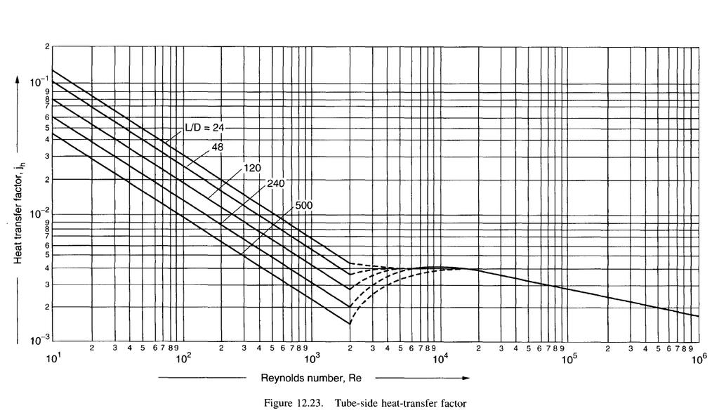
58 58
59 Equation can be rearranged to a more convenient form: Kern (1950)define the heat transfer factor as: The relationship between j h and J H is given by: 60
60 Tube-side pressure drop There are two major sources of pressure loss on the tube-side of a shell and tube exchanger: The friction loss in the tubes and The losses due to the sudden contraction and expansion and minor source of pressure loss : flow reversals that the fluid experiences in flow through the tube arrangement. The tube friction loss can be calculated using the familiar equations for pressure-drop loss in pipes. (see fluid mechanics). 61
61 The basic equation for isothermal flow in pipes (constant temperature) is: where j f is the dimensionless friction factor and L' is the effective pipe length. 62
62 The flow in a heat exchanger will clearly not be isothermal, and this is allowed for by including an empirical correction factor to account for the change in physical properties with temperature. Normally only the change in viscosity is considered: Values of j f for heat exchanger tubes can be obtained from Figure. 63
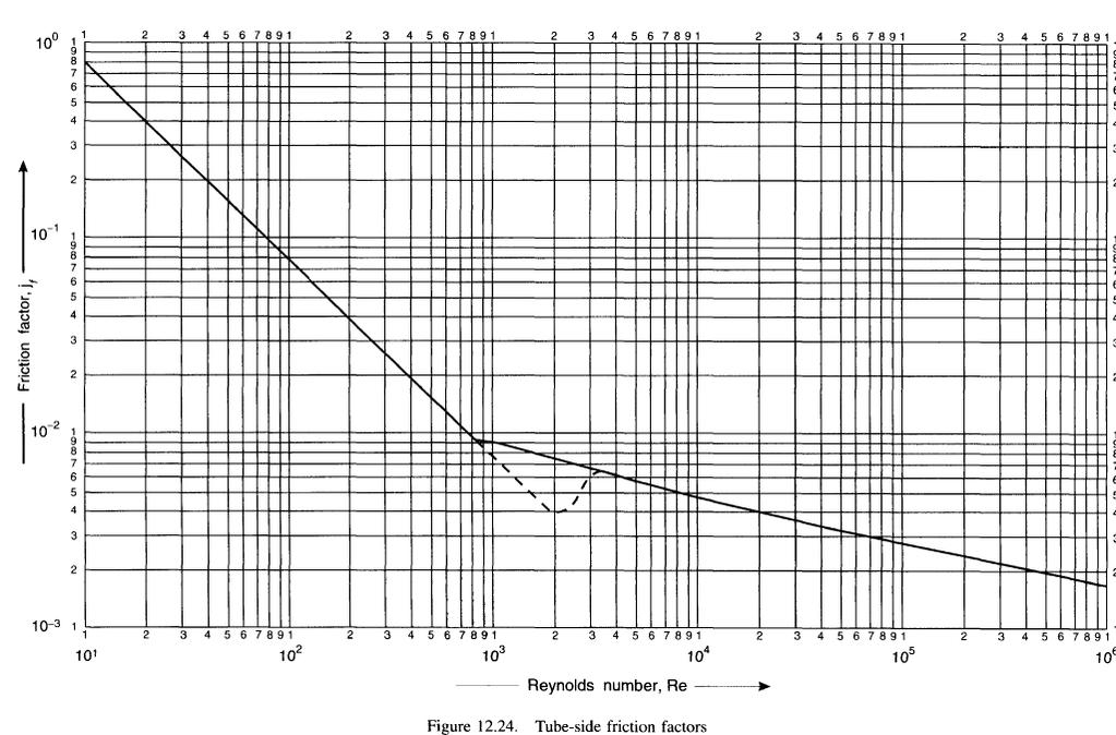
63 64
64 The pressure losses due to contraction at the tube inlets, expansion at the exits, and flow reversal in the headers, can be a significant part of the total tube-side pressure drop. There is no entirely satisfactory method for estimating these losses. Kern (1950) suggests adding four velocity heads per pass. Frank (1978) considers this to be too high, and recommends 2.5 velocity heads. Butterworth (1978) suggests 1.8. Lord et al. (1970) take the loss per pass as equivalent to a length of tube equal to 300 tube diameters for straight tubes, and 200 for U- tubes; whereas Evans (1980) appears to add only 67 tube diameters per pass. 65
65 The loss in terms of velocity heads can be estimated by counting the number of flow contractions, expansions and reversals, and using the factors for pipe fittings to estimate the number of velocity heads lost. For two tube passes, there will be two contractions, two expansions and one flow reversal. The head loss for each of these effects is: contraction 0.5, expansion 1.0, 180 bend 1.5; so for two passes the maximum loss will be 2 x x = 4.5 velocity heads = 2.25 per pass 66
66 From this, it appears that Frank's recommended value of 2.5 velocity heads per pass is the most realistic value to use. 67
67 Viscosity Correction Factor The viscosity correction factor will normally only be significant for viscous liquids. 68
68 Coefficients For Water The equation below has been adapted from data given by Eagle and Ferguson (1930): where h i = inside coefficient, for water, W/m 2 C, t = water temperature, C, u t = water velocity, m/s, d i = tube inside diameter, mm. 69
69 Shell-Side Heat-Transfer And Pressure Drop (Single Phase) 70
70 71
71 DESIGN METHODS Kern Method Bell or Bell-Delware Method 72
72 KERN'S METHOD The shell equivalent diameter is calculated using the flow area between the tubes taken in the axial direction (parallel to the tubes) and the wetted perimeter of the tubes; 73
73 Procedure 1. Calculate the area for cross-flow As for the hypothetical row of tubes at the shell equator, given by: 74
74 2. Calculate the shell-side mass velocity G s and the linear velocity u s : where W s = fluid flow-rate on the shell-side, kg/s, ρ = shell-side fluid density, kg/m 3. 75
75 3. Calculate the shell-side equivalent diameter (hydraulic diameter), D D D e e e 4 free flow area wetted perimeter 4 P 4 P 2 T 2 T d d o 2 o / 4 Where D e = equivalent diameter in m 3 / 4 d d / 2 o 2 o square / 8 triangular 76
76 4. Calculate the shell-side Reynolds number, given by: 77
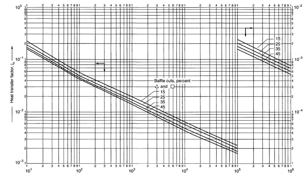
77 5. For the calculated Reynolds number, read the value of j h, from graph for the selected baffle cut and tube arrangement, and calculate the shell-side heat transfer coefficient h s from: 78
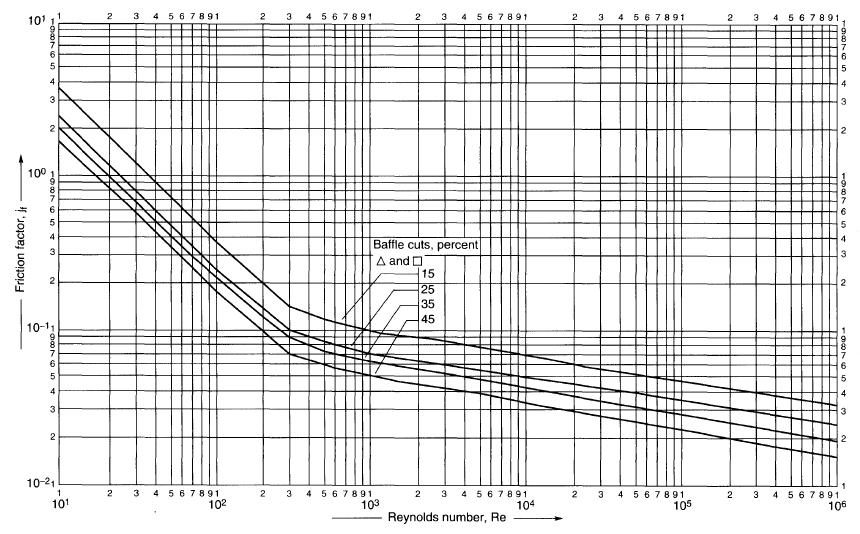
78 6. For the calculated shell-side Reynolds number, read the friction factor from graph and calculate the shell-side pressure drop from: where L = tube length, I B = baffle spacing. The term (L/l B ) is the number of times the flow crosses the tube bundle = (N b + 1), where N b, is the number of baffles. 79
79 80
80 81
81 Heat Exchanger Shell Side Design Bell Method
 Flow")
82 SHELL-SIDE HEAT-TRANSFER AND PRESSURE DROP (SINGLE PHASE) Flow pattern
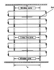
83 Bell s method In Bell s method the heat-transfer coefficient and pressure drop are estimated from correlations for flow over ideal tubebanks, and the effects of leakage, bypassing and flow in the window zone are allowed for by applying correction factors.
84 Heat-transfer coefficient The total correction will vary from 0.6 for a poorly designed exchanger with large clearances to 0.9 for a well-designed exchanger.

85 h oc, ideal cross-flow coefficient
86
87 F n, tube row correction factor
88 F w, window correction factor
89 F b, bypass correction factor With sealing strips
90 Where no sealing strips are used, F b can be obtained from Figure
91 F L, Leakage correction factor
92
93 Shell and bundle geometry

94
95
96
97
98
99 Pressure drop Cross-flow zones The pressure drop in the cross-flow zones between the baffle tips is calculated from correlations for ideal tube banks, and corrected for leakage and bypassing.
100 Pressure Drop ideal tube bank pressure drop The number of tube rows has little effect on the friction factor and is ignored.
101
102 F b, bypass correction factor for pressure drop Bypassing will affect the pressure drop only in the cross-flow zones. The correction factor is calculated from the equation used to calculate the bypass correction factor for heat transfer,
103
104 F L, leakage factor for pressure drop
105 Window-zone pressure drop
106 End zone pressure drop
107 Total shell-side pressure drop

108 THANK YOU
HEAT TRANSFER. Mechanisms of Heat Transfer: (1) Conduction
 Conduction") HEAT TRANSFER Mechanisms of Heat Transfer: (1) Conduction where Q is the amount of heat, Btu, transferred in time t, h k is the thermal conductivity, Btu/[h ft 2 ( o F/ft)] A is the area of heat transfer
HEAT TRANSFER Mechanisms of Heat Transfer: (1) Conduction where Q is the amount of heat, Btu, transferred in time t, h k is the thermal conductivity, Btu/[h ft 2 ( o F/ft)] A is the area of heat transfer
DESIGN OF A SHELL AND TUBE HEAT EXCHANGER
 DESIGN OF A SHELL AND TUBE HEAT EXCHANGER Swarnotpal Kashyap Department of Chemical Engineering, IIT Guwahati, Assam, India 781039 ABSTRACT Often, in process industries the feed stream has to be preheated
Heat Transfer Equipment
 Università di Pisa Facoltà di Ingegneria Heat Transfer Equipment Unit Operation I Prof. Cristiano Nicolella Typical overall heat transfer coefficients Fouling factors Frank nomograph Fouling factors Exchanger
DESIGN AND COST ANALYSIS OF HEAT TRANSFER EQUIPMENTS
 DESIGN AND COST ANALYSIS OF HEAT TRANSFER EQUIPMENTS Md. Khairul Islam Lecturer Department of Applied Chemistry and Chemical Engineering. University of Rajshahi. What is design? Design includes all the
INTRODUCTION: Shell and tube heat exchangers are one of the most common equipment found in all plants. How it works?
 HEAT EXCHANGERS 1 INTRODUCTION: Shell and tube heat exchangers are one of the most common equipment found in all plants How it works? 2 WHAT ARE THEY USED FOR? Classification according to service. Heat
8.1 Technically Feasible Design of a Heat Exchanger
 328 Technically Feasible Design Case Studies T 2 q 2 ρ 2 C p2 T F q ρ C p T q ρ C p T 2F q 2 ρ 2 C p2 Figure 3.5. Countercurrent double-pipe exchanger. 8. Technically Feasible Design of a Heat Exchanger
SHELL-AND-TUBE TEST PROBLEMS
 SHELL-AND-TUBE TEST PROBLEMS The problems that have been used to validate some of the capabilities in INSTED for the analysis of shell-and-tube heat exchanger are discussed in this chapter. You should
WTS Table of contents. Layout
 Table of contents Thermal and hydraulic design of shell and tube heat exchangers... 2 Tube sheet data... 4 Properties of Water and Steam... 6 Properties of Water and Steam... 7 Heat transfer in pipe flow...
طراحی مبدل های حرارتی مهدي کریمی ترم بهار HEAT TRANSFER CALCULATIONS
 طراحی مبدل های حرارتی مهدي کریمی ترم بهار 96-97 HEAT TRANSFER CALCULATIONS ١ TEMPERATURE DIFFERENCE For any transfer the driving force is needed General heat transfer equation : Q = U.A. T What T should
Thermal Design of Shell and tube heat Exchanger
 King Abdulaziz University Mechanical Engineering Department MEP 460 Heat Exchanger Design Thermal Design of Shell and tube heat Exchanger March 2018 1 Contents 1-Introduction 2-Basic components Shell types
Design and rating of Shell and tube heat Exchangers Bell-Delaware method
 King Abdulaziz University Mechanical Engineering Department MEP 460 Heat Exchanger Design Design and rating of Shell and tube heat Exchangers Bell-Delaware method 1 April 2018 Bell Delaware method for
HEAT TRANSFER. PHI Learning PfcO too1. Principles and Applications BINAY K. DUTTA. Delhi Kolkata. West Bengal Pollution Control Board
 HEAT TRANSFER Principles and Applications BINAY K. DUTTA West Bengal Pollution Control Board Kolkata PHI Learning PfcO too1 Delhi-110092 2014 Contents Preface Notations ix xiii 1. Introduction 1-8 1.1
Chapter 11: Heat Exchangers. Dr Ali Jawarneh Department of Mechanical Engineering Hashemite University
 Chapter 11: Heat Exchangers Dr Ali Jawarneh Department of Mechanical Engineering Hashemite University Objectives When you finish studying this chapter, you should be able to: Recognize numerous types of
Convection Heat Transfer. Introduction
 Convection Heat Transfer Reading Problems 12-1 12-8 12-40, 12-49, 12-68, 12-70, 12-87, 12-98 13-1 13-6 13-39, 13-47, 13-59 14-1 14-4 14-18, 14-24, 14-45, 14-82 Introduction Newton s Law of Cooling Controlling
If there is convective heat transfer from outer surface to fluid maintained at T W.
 Heat Transfer 1. What are the different modes of heat transfer? Explain with examples. 2. State Fourier s Law of heat conduction? Write some of their applications. 3. State the effect of variation of temperature
Introduction to Heat and Mass Transfer
 Introduction to Heat and Mass Transfer Week 16 Merry X mas! Happy New Year 2019! Final Exam When? Thursday, January 10th What time? 3:10-5 pm Where? 91203 What? Lecture materials from Week 1 to 16 (before
HEAT TRANSFER AND EXCHANGERS
 HEAT TRANSFER AND EXCHANGERS Although heat-transfer rates can be computed with reasonable accuracy for clean or new pipe, the effect of dirty or corroded pipe surfaces cannot he satisfactorily estimated.
Heat and Mass Transfer Unit-1 Conduction
 1. State Fourier s Law of conduction. Heat and Mass Transfer Unit-1 Conduction Part-A The rate of heat conduction is proportional to the area measured normal to the direction of heat flow and to the temperature
Heat processes. Heat exchange
 Heat processes Heat exchange Heat energy transported across a surface from higher temperature side to lower temperature side; it is a macroscopic measure of transported energies of molecular motions Temperature
23 1 TYPES OF HEAT EXCHANGERS
 cen5426_ch23.qxd /26/04 9:42 AM Page 032 032 FUNDAMENTALS OF THERMAL-FLUID SCIENCES 23 TYPES OF HEAT EXCHANGERS Different heat transfer applications require different types of hardware different configurations
ME 331 Homework Assignment #6
 ME 33 Homework Assignment #6 Problem Statement: ater at 30 o C flows through a long.85 cm diameter tube at a mass flow rate of 0.020 kg/s. Find: The mean velocity (u m ), maximum velocity (u MAX ), and
Tutorial 1. Where Nu=(hl/k); Reynolds number Re=(Vlρ/µ) and Prandtl number Pr=(µCp/k)
; Reynolds number Re=(Vlρ/µ) and Prandtl number Pr=(µCp/k)") Tutorial 1 1. Explain in detail the mechanism of forced convection. Show by dimensional analysis (Rayleigh method) that data for forced convection may be correlated by an equation of the form Nu = φ (Re,
Tutorial 1 1. Explain in detail the mechanism of forced convection. Show by dimensional analysis (Rayleigh method) that data for forced convection may be correlated by an equation of the form Nu = φ (Re,
CONCENTRIC EXCHANGER TEST PROBLEMS
 CONCENTRIC EXCHANGER TEST PROBLEMS Introduction The tests used to validate INSTED analysis of concentric exchanger module are presented here. You may need to consult the original sources of the various
UNIT II CONVECTION HEAT TRANSFER
 UNIT II CONVECTION HEAT TRANSFER Convection is the mode of heat transfer between a surface and a fluid moving over it. The energy transfer in convection is predominately due to the bulk motion of the fluid
Chapter 3 NATURAL CONVECTION
 Fundamentals of Thermal-Fluid Sciences, 3rd Edition Yunus A. Cengel, Robert H. Turner, John M. Cimbala McGraw-Hill, 2008 Chapter 3 NATURAL CONVECTION Mehmet Kanoglu Copyright The McGraw-Hill Companies,
Overall Heat Transfer Coefficient
 Overall Heat Transfer Coefficient A heat exchanger typically involves two flowing fluids separated by a solid wall. Heat is first transferred from the hot fluid to the wall by convection, through the wall
: HEAT TRANSFER & EVAPORATION COURSE CODE : 4072 COURSE CATEGORY : B PERIODS/ WEEK : 5 PERIODS/ SEMESTER : 70 CREDIT : 5 TIME SCHEDULE
 COURSE TITLE : HEAT TRANSFER & EVAPORATION COURSE CODE : 4072 COURSE CATEGORY : B PERIODS/ WEEK : 5 PERIODS/ SEMESTER : 70 CREDIT : 5 TIME SCHEDULE MODULE TOPIC PERIODS 1 Conduction,Fourier law,variation
TankExampleNov2016. Table of contents. Layout
 Table of contents Task... 2 Calculation of heat loss of storage tanks... 3 Properties ambient air Properties of air... 7 Heat transfer outside, roof Heat transfer in flow past a plane wall... 8 Properties
Designing Steps for a Heat Exchanger ABSTRACT
 Designing Steps for a Heat Exchanger Reetika Saxena M.Tech. Student in I.F.T.M. University, Moradabad Sanjay Yadav 2 Asst. Prof. in I.F.T.M. University, Moradabad ABSTRACT Distillation is a common method
Outlines. simple relations of fluid dynamics Boundary layer analysis. Important for basic understanding of convection heat transfer
 Forced Convection Outlines To examine the methods of calculating convection heat transfer (particularly, the ways of predicting the value of convection heat transfer coefficient, h) Convection heat transfer
Convection. forced convection when the flow is caused by external means, such as by a fan, a pump, or atmospheric winds.
 Convection The convection heat transfer mode is comprised of two mechanisms. In addition to energy transfer due to random molecular motion (diffusion), energy is also transferred by the bulk, or macroscopic,
Keywords: Spiral plate heat exchanger, Heat transfer, Nusselt number
 EXPERIMENTAL AND NUMERICAL STUDIES OF A SPIRAL PLATE HEAT EXCHANGER Dr.RAJAVEL RANGASAMY Professor and Head, Department of Mechanical Engineering Velammal Engineering College,Chennai -66,India Email:rajavelmech@gmail.com
TUBE BANKS TEST PROBLEMS
 TUBE BANKS TEST PROBLEMS The non-proprietary tests used to validate INSTED analysis of flow and heat transfer over tube banks are presented in this section. You may need to consult the original sources
Level 7 Post Graduate Diploma in Engineering Heat and mass transfer
 9210-221 Level 7 Post Graduate Diploma in Engineering Heat and mass transfer 0 You should have the following for this examination one answer book non programmable calculator pen, pencil, drawing instruments
THERMAL DESIGN OF FALLING FILM EVAPORATOR
 YMCA Institute of Engineering, Faridabad, Haryana.., Dec 9-10, 006. THERMAL DESIGN OF FALLING FILM EVAPORATOR Ashik Patel 1, Manish purohit, C. R. Sonawane 3 1, Department of Mechanical Engineering Students,
Analysis of Heat Transfer Enhancement in Spiral Plate Heat Exchanger
 Vol. 2, No. 4 Modern Applied Science Analysis of Heat Transfer Enhancement in Spiral Plate Heat Exchanger Dr. Kaliannan Saravanan Professor & Head, Department of Chemical Engineering Kongu Engineering
PHYSICAL MECHANISM OF CONVECTION
 Tue 8:54:24 AM Slide Nr. 0 of 33 Slides PHYSICAL MECHANISM OF CONVECTION Heat transfer through a fluid is by convection in the presence of bulk fluid motion and by conduction in the absence of it. Chapter
INSTRUCTOR: PM DR MAZLAN ABDUL WAHID
 SMJ 4463: HEAT TRANSFER INSTRUCTOR: PM DR MAZLAN ABDUL WAHID http://www.fkm.utm.my/~mazlan TEXT: Introduction to Heat Transfer by Incropera, DeWitt, Bergman, Lavine 5 th Edition, John Wiley and Sons DR
Lecture 30 Review of Fluid Flow and Heat Transfer
 Objectives In this lecture you will learn the following We shall summarise the principles used in fluid mechanics and heat transfer. It is assumed that the student has already been exposed to courses in
Heat Transfer Convection
 Heat ransfer Convection Previous lectures conduction: heat transfer without fluid motion oday (textbook nearly 00 pages) Convection: heat transfer with fluid motion Research methods different Natural Convection
Ben Wolfe 11/3/14. Figure 1: Theoretical diagram showing the each step of heat loss.
 Condenser Analysis Water Cooled Model: For this condenser design there will be a coil of stainless steel tubing suspended in a bath of cold water. The cold water will be stationary and begin at an ambient
Phone: , For Educational Use. SOFTbank E-Book Center, Tehran. Fundamentals of Heat Transfer. René Reyes Mazzoco
 8 Fundamentals of Heat Transfer René Reyes Mazzoco Universidad de las Américas Puebla, Cholula, Mexico 1 HEAT TRANSFER MECHANISMS 1.1 Conduction Conduction heat transfer is explained through the molecular
In order to optimize the shell and coil heat exchanger design using the model presented in Chapter
 1 CHAPTER FOUR The Detailed Model In order to optimize the shell and coil heat exchanger design using the model presented in Chapter 3, one would have to build several heat exchanger prototypes, and then
Examination Heat Transfer
 Examination Heat Transfer code: 4B680 date: 17 january 2006 time: 14.00-17.00 hours NOTE: There are 4 questions in total. The first one consists of independent sub-questions. If necessary, guide numbers
S.E. (Chemical) (Second Semester) EXAMINATION, 2012 HEAT TRANSFER (2008 PATTERN) Time : Three Hours Maximum Marks : 100
 (Second Semester) EXAMINATION, 2012 HEAT TRANSFER (2008 PATTERN) Time : Three Hours Maximum Marks : 100") Total No. of Questions 12] [Total No. of Printed Pages 7 Seat No. [4162]-187 S.E. (Chemical) (Second Semester) EXAMINATION, 2012 HEAT TRANSFER (2008 PATTERN) Time : Three Hours Maximum Marks : 100 N.B.
Total No. of Questions 12] [Total No. of Printed Pages 7 Seat No. [4162]-187 S.E. (Chemical) (Second Semester) EXAMINATION, 2012 HEAT TRANSFER (2008 PATTERN) Time : Three Hours Maximum Marks : 100 N.B.
Forced Convection: Inside Pipe HANNA ILYANI ZULHAIMI
 + Forced Convection: Inside Pipe HANNA ILYANI ZULHAIMI + OUTLINE u Introduction and Dimensionless Numbers u Heat Transfer Coefficient for Laminar Flow inside a Pipe u Heat Transfer Coefficient for Turbulent
COMPARATIVE THERMAL ANALYSIS OF CONVENTIONAL TUBULAR HEAT EXCHANGER WITH HELIXCHANGER USING BELL-DELAWARE METHOD
 COMPARATIVE THERMAL ANALYSIS OF CONVENTIONAL TUBULAR HEAT EXCHANGER WITH HELIXCHANGER USING BELL-DELAWARE METHOD Prof.S.S.SHINDE 1*, P.V.HADGEKAR 2, Dr.S.PAVITRAN 3 1 Department of Mechanical Engineering
DESIGN AND EXPERIMENTAL ANALYSIS OF SHELL AND TUBE HEAT EXCHANGER (U-TUBE)
") DESIGN AND EXPERIMENTAL ANALYSIS OF SHELL AND TUBE HEAT EXCHANGER (U-TUBE) Divyesh B. Patel 1, Jayesh R. Parekh 2 Assistant professor, Mechanical Department, SNPIT&RC, Umrakh, Gujarat, India 1 Assistant
DESIGN AND EXPERIMENTAL ANALYSIS OF SHELL AND TUBE HEAT EXCHANGER (U-TUBE) Divyesh B. Patel 1, Jayesh R. Parekh 2 Assistant professor, Mechanical Department, SNPIT&RC, Umrakh, Gujarat, India 1 Assistant
EXPERIMENTAL AND NUMERICAL STUDIES OF A SPIRAL PLATE HEAT EXCHANGER
 THERMAL SCIENCE: Year 2014, Vol. 18, No. 4, pp. 1355-1360 1355 EXPERIMENTAL AND NUMERICAL STUDIES OF A SPIRAL PLATE HEAT EXCHANGER by Rangasamy RAJAVEL Department of Mechanical Engineering, AMET University,
Heat Transfer Predictions for Carbon Dioxide in Boiling Through Fundamental Modelling Implementing a Combination of Nusselt Number Correlations
 Heat Transfer Predictions for Carbon Dioxide in Boiling Through Fundamental Modelling Implementing a Combination of Nusselt Number Correlations L. Makaum, P.v.Z. Venter and M. van Eldik Abstract Refrigerants
Lectures on Applied Reactor Technology and Nuclear Power Safety. Lecture No 6
 Lectures on Nuclear Power Safety Lecture No 6 Title: Introduction to Thermal-Hydraulic Analysis of Nuclear Reactor Cores Department of Energy Technology KTH Spring 2005 Slide No 1 Outline of the Lecture
Transfer processes: direct contact or indirect contact. Geometry of construction: tubes, plates, and extended surfaces
 Chapter 5 Heat Exchangers 5.1 Introduction Heat exchangers are devices used to transfer heat between two or more fluid streams at different temperatures. Heat exchangers find widespread use in power generation,
Chapter 7: External Forced Convection. Dr Ali Jawarneh Department of Mechanical Engineering Hashemite University
 Chapter 7: External Forced Convection Dr Ali Jawarneh Department of Mechanical Engineering Hashemite University Objectives When you finish studying this chapter, you should be able to: Distinguish between
Principles of Convection
 Principles of Convection Point Conduction & convection are similar both require the presence of a material medium. But convection requires the presence of fluid motion. Heat transfer through the: Solid
Principles of Food and Bioprocess Engineering (FS 231) Problems on Heat Transfer
 Problems on Heat Transfer") Principles of Food and Bioprocess Engineering (FS 1) Problems on Heat Transfer 1. What is the thermal conductivity of a material 8 cm thick if the temperature at one end of the product is 0 C and the temperature
Principles of Food and Bioprocess Engineering (FS 1) Problems on Heat Transfer 1. What is the thermal conductivity of a material 8 cm thick if the temperature at one end of the product is 0 C and the temperature
CHME 302 CHEMICAL ENGINEERING LABOATORY-I EXPERIMENT 302-V FREE AND FORCED CONVECTION
 CHME 302 CHEMICAL ENGINEERING LABOATORY-I EXPERIMENT 302-V FREE AND FORCED CONVECTION OBJECTIVE The objective of the experiment is to compare the heat transfer characteristics of free and forced convection.
CHAPTER 5 CONVECTIVE HEAT TRANSFER COEFFICIENT
 62 CHAPTER 5 CONVECTIVE HEAT TRANSFER COEFFICIENT 5.1 INTRODUCTION The primary objective of this work is to investigate the convective heat transfer characteristics of silver/water nanofluid. In order
Design and Temperature Analysis on Heat Exchanger with TEMA Standard Codes
 Design and Temperature Analysis on Heat Exchanger with TEMA Standard Codes Adesh Dhope 1, Omkar Desai 2, Prof. V. Verma 3 1 Student, Department of Mechanical Engineering,Smt. KashibaiNavale college of
NUMERICAL HEAT TRANSFER ENHANCEMENT IN SQUARE DUCT WITH INTERNAL RIB
 NUMERICAL HEAT TRANSFER ENHANCEMENT IN SQUARE DUCT WITH INTERNAL RIB University of Technology Department Mechanical engineering Baghdad, Iraq ABSTRACT - This paper presents numerical investigation of heat
Specific heat capacity. Convective heat transfer coefficient. Thermal diffusivity. Lc ft, m Characteristic length (r for cylinder or sphere; for slab)
") Important Heat Transfer Parameters CBE 150A Midterm #3 Review Sheet General Parameters: q or or Heat transfer rate Heat flux (per unit area) Cp Specific heat capacity k Thermal conductivity h Convective
Important Heat Transfer Parameters CBE 150A Midterm #3 Review Sheet General Parameters: q or or Heat transfer rate Heat flux (per unit area) Cp Specific heat capacity k Thermal conductivity h Convective
Analysis of Shell & Tube Type Heat Exchangers
 Analysis of Shell & Tube Type Heat Exchangers Ajay Kumar Giri, Navesh Kumar Roul, Tarini Prakash Mishra, Mr. Debabrata panda, Mr. Ajit Prasad Dash Department of mechanical engineering, GIET GUNUPUR Email:
INTERNATIONAL JOURNAL OF PURE AND APPLIED RESEARCH IN ENGINEERING AND TECHNOLOGY
 INTERNATIONAL JOURNAL OF PURE AND APPLIED RESEARCH IN ENGINEERING AND TECHNOLOGY A PATH FOR HORIZING YOUR INNOVATIVE WORK EXPERIENTIAL INVESTIGATION OF SHELL AND TUBE HEAT EXCHANGER USING KERN METHOD K
OUTCOME 2 - TUTORIAL 1
 Unit 4: Heat Transfer and Combustion Unit code: K/60/44 QCF level: 5 Credit value: 5 OUTCOME - TUTORIAL Heat transfer coefficients Dimensional analysis: dimensionless groups; Reynolds, Nusselt, Prandtl,
How can we use Fundamental Heat Transfer to understand real devices like heat exchangers?
 Lectures 7+8 04 CM30 /30/05 CM30 Transport I Part II: Heat Transfer Applied Heat Transfer: Heat Exchanger Modeling, Sizing, and Design Professor Faith Morrison Department of Chemical Engineering Michigan
Heat Exchanger Design
 Heat Exchanger Design Heat Exchanger Design Methodology Design is an activity aimed at providing complete descriptions of an engineering system, part of a system, or just a single system component. These
Heat Exchangers: Rating & Performance Parameters. Maximum Heat Transfer Rate, q max
 Heat Exchangers: Rating & Performance Parameters Dr. Md. Zahurul Haq HTX Rating is concerned with the determination of the heat transfer rate, fluid outlet temperatures, and the pressure drop for an existing
c Dr. Md. Zahurul Haq (BUET) Heat Exchangers: Rating & Sizing - I ME 307 (2017) 2 / 32 T666
 Heat Exchangers: Rating & Sizing - I ME 307 (2017) 2 / 32 T666") Heat Exchanger: Rating & Sizing Heat Exchangers: Rating & Sizing - I Dr. Md. Zahurul Haq Professor Department of Mechanical Engineering Bangladesh University of Engineering & Technology (BUET) Dhaka-000,
Heat Exchanger: Rating & Sizing Heat Exchangers: Rating & Sizing - I Dr. Md. Zahurul Haq Professor Department of Mechanical Engineering Bangladesh University of Engineering & Technology (BUET) Dhaka-000,
Applied Heat Transfer:
 Lectures 7+8 CM30 /6/06 CM30 Transport I Part II: Heat Transfer Applied Heat Transfer: Heat Exchanger Modeling, Sizing, and Design Professor Faith Morrison Department of Chemical Engineering Michigan Technological
HEAT TRANSFER BY CONVECTION. Dr. Şaziye Balku 1
 HEAT TRANSFER BY CONVECTION Dr. Şaziye Balku 1 CONDUCTION Mechanism of heat transfer through a solid or fluid in the absence any fluid motion. CONVECTION Mechanism of heat transfer through a fluid in the
Water Circuit Lab. The pressure drop along a straight pipe segment can be calculated using the following set of equations:
 Water Circuit Lab When a fluid flows in a conduit, there is friction between the flowing fluid and the pipe walls. The result of this friction is a net loss of energy in the flowing fluid. The fluid pressure
True/False. Circle the correct answer. (1pt each, 7pts total) 3. Radiation doesn t occur in materials that are transparent such as gases.
 3. Radiation doesn t occur in materials that are transparent such as gases.") ME 323 Sample Final Exam. 120pts total True/False. Circle the correct answer. (1pt each, 7pts total) 1. A solid angle of 2π steradians defines a hemispherical shell. T F 2. The Earth irradiates the Sun.
ME 323 Sample Final Exam. 120pts total True/False. Circle the correct answer. (1pt each, 7pts total) 1. A solid angle of 2π steradians defines a hemispherical shell. T F 2. The Earth irradiates the Sun.
PROBLEM 8.3 ( ) p = kg m 1m s m 1000 m = kg s m = bar < P = N m 0.25 m 4 1m s = 1418 N m s = 1.
 p = kg m 1m s m 1000 m = kg s m = bar < P = N m 0.25 m 4 1m s = 1418 N m s = 1.") PROBLEM 8.3 KNOWN: Temperature and velocity of water flow in a pipe of prescribed dimensions. FIND: Pressure drop and pump power requirement for (a) a smooth pipe, (b) a cast iron pipe with a clean surface,
PROBLEM 8.3 KNOWN: Temperature and velocity of water flow in a pipe of prescribed dimensions. FIND: Pressure drop and pump power requirement for (a) a smooth pipe, (b) a cast iron pipe with a clean surface,
Convective Mass Transfer
 Convective Mass Transfer Definition of convective mass transfer: The transport of material between a boundary surface and a moving fluid or between two immiscible moving fluids separated by a mobile interface
A computer program for designing of shell-and-tube heat exchangers
 Applied Thermal Engineering 24(2004) 1797 1805 www.elsevier.com/locate/apthermeng A computer program for designing of shell-and-tube heat exchangers Yusuf Ali Kara *, Ozbilen G uraras Department of Mechanical
Study on the improved recuperator design used in the direct helium-turbine power conversion cycle of HTR-10
 Study on the improved recuperator design used in the direct helium-turbine power conversion cycle of HTR-10 Wu Xinxin 1), Xu Zhao ) 1) Professor, INET, Tsinghua University, Beijing, P.R.China (xinxin@mail.tsinghua.edu.cn)
Piping Systems and Flow Analysis (Chapter 3)
") Piping Systems and Flow Analysis (Chapter 3) 2 Learning Outcomes (Chapter 3) Losses in Piping Systems Major losses Minor losses Pipe Networks Pipes in series Pipes in parallel Manifolds and Distribution
Piping Systems and Flow Analysis (Chapter 3) 2 Learning Outcomes (Chapter 3) Losses in Piping Systems Major losses Minor losses Pipe Networks Pipes in series Pipes in parallel Manifolds and Distribution
Axial profiles of heat transfer coefficients in a liquid film evaporator
 Axial profiles of heat transfer coefficients in a liquid film evaporator Pavel Timár, Ján Stopka, Vladimír Báleš Department of Chemical and Biochemical Engineering, Faculty of Chemical and Food Technology,
CONVECTIVE HEAT TRANSFER
 CONVECTIVE HEAT TRANSFER Mohammad Goharkhah Department of Mechanical Engineering, Sahand Unversity of Technology, Tabriz, Iran CHAPTER 4 HEAT TRANSFER IN CHANNEL FLOW BASIC CONCEPTS BASIC CONCEPTS Laminar
Chemical and Biomolecular Engineering 150A Transport Processes Spring Semester 2017
 Chemical and Biomolecular Engineering 150A Transport Processes Spring Semester 2017 Objective: Text: To introduce the basic concepts of fluid mechanics and heat transfer necessary for solution of engineering
Introduction to Heat Transfer
 Question Bank CH302 Heat Transfer Operations Introduction to Heat Transfer Question No. 1. The essential condition for the transfer of heat from one body to another (a) Both bodies must be in physical
PHYSICAL MECHANISM OF NATURAL CONVECTION
 1 NATURAL CONVECTION In this chapter, we consider natural convection, where any fluid motion occurs by natural means such as buoyancy. The fluid motion in forced convection is quite noticeable, since a
Analytical Study on Thermal and Mechanical Design of Printed Circuit Heat Exchanger
 INL/EXT-13-30047 Analytical Study on Thermal and Mechanical Design of Printed Circuit Heat Exchanger Su-Jong Yoon Piyush Sabharwall Eung-Soo Kim September 2013 The INL is a U.S. Department of Energy National
Liquid or gas flow through pipes or ducts is commonly used in heating and
 cen58933_ch08.qxd 9/4/2002 11:29 AM Page 419 INTERNAL FORCED CONVECTION CHAPTER 8 Liquid or gas flow through pipes or ducts is commonly used in heating and cooling applications. The fluid in such applications
Welcome to the course in Heat Transfer (MMV031) L1. Martin Andersson & Zan Wu
 L1. Martin Andersson & Zan Wu") Welcome to the course in Heat Transfer (MMV031) L1 Martin Andersson & Zan Wu Agenda Organisation Introduction to Heat Transfer Heat Exchangers (Ex 108) Course improvement compared to last years 2017: Amount
Welcome to the course in Heat Transfer (MMV031) L1 Martin Andersson & Zan Wu Agenda Organisation Introduction to Heat Transfer Heat Exchangers (Ex 108) Course improvement compared to last years 2017: Amount
Plant Design LECTURE 8: REBOILER CIRCUIT DESIGN. Daniel R. Lewin Department of Chemical Engineering Technion, Haifa, Israel
 054410 Plant Design LECTURE 8: REBOILER CIRCUIT DESIGN Daniel R. Lewin Department of Chemical Engineering Technion, Haifa, Israel Ref: Kern, R. Thermosyphon Reboiler Piping Simplified, Hydrocarbon Processing,
Journal of NUCLEAR SCIENCE and TECHNOLOGY, Vol. 41, No. 7, p (July 2004)
") Journal of NUCLEAR SCIENCE and TECHNOLOGY, Vol. 41, No. 7, p. 765 770 (July 2004) TECHNICAL REPORT Experimental and Operational Verification of the HTR-10 Once-Through Steam Generator (SG) Heat-transfer
Journal of NUCLEAR SCIENCE and TECHNOLOGY, Vol. 41, No. 7, p. 765 770 (July 2004) TECHNICAL REPORT Experimental and Operational Verification of the HTR-10 Once-Through Steam Generator (SG) Heat-transfer
1/54 Circulation pump, safety valve, expansion vessel
 1/54 Circulation pump, safety valve, expansion vessel pressure loss efficiency of pump secured heat output safety valve sizing expansion vessel sizing Circulation pump 2/54 similar principle as for heating
CHAPTER FOUR HEAT TRANSFER
 CHAPTER FOUR HEAT TRANSFER 4.1. Determination of Overall Heat Transfer Coefficient in a Tubular Heat Exchanger 4.2. Determination of Overall Heat Transfer Coefficient in a Plate Type Heat Exchanger 4.3.
PERFORMANCE ANALYSIS OF CORRUGATED PLATE HEAT EXCHANGER WITH WATER AS WORKING FLUID
 PERFORMANCE ANALYSIS OF CORRUGATED PLATE HEAT EXCHANGER WITH WATER AS WORKING FLUID Tisekar Salman W 1, Mukadam Shakeeb A 2, Vedpathak Harshad S 3, Rasal Priyanka K 4, Khandekar S. B 5 1 Student of B.E.,
The Research of Heat Transfer Area for 55/19 Steam Generator
 Journal of Power and Energy Engineering, 205, 3, 47-422 Published Online April 205 in SciRes. http://www.scirp.org/journal/jpee http://dx.doi.org/0.4236/jpee.205.34056 The Research of Heat Transfer Area
MYcsvtu Notes HEAT TRANSFER BY CONVECTION
 www.mycsvtunotes.in HEAT TRANSFER BY CONVECTION CONDUCTION Mechanism of heat transfer through a solid or fluid in the absence any fluid motion. CONVECTION Mechanism of heat transfer through a fluid in
Experimental Investigation of Single-Phase Friction Factor and Heat Transfer inside the Horizontal Internally Micro-Fin Tubes.
 Experimental Investigation of Single-Phase Friction Factor and Heat Transfer inside the Horizontal Internally Micro-Fin Tubes by Sun Cheong Master of Science in Electromechanical Engineering 2013 Faculty
Circle one: School of Mechanical Engineering Purdue University ME315 Heat and Mass Transfer. Exam #2. April 3, 2014
 Circle one: Div. 1 (12:30 pm, Prof. Choi) Div. 2 (9:30 am, Prof. Xu) School of Mechanical Engineering Purdue University ME315 Heat and Mass Transfer Exam #2 April 3, 2014 Instructions: Write your name
HEAT EXCHANGER. Objectives
 HEAT EXCHANGER Heat exchange is an important unit operation that contributes to efficiency and safety of many processes. In this project you will evaluate performance of three different types of heat exchangers
10 minutes reading time is allowed for this paper.
 EGT1 ENGINEERING TRIPOS PART IB Tuesday 31 May 2016 2 to 4 Paper 4 THERMOFLUID MECHANICS Answer not more than four questions. Answer not more than two questions from each section. All questions carry the
Effect of tube pitch on heat transfer in shell-and-tube heat exchangers new simulation software
 Heat Mass Transfer (2006) 42: 263 270 DOI 0.007/s0023-005-0002-9 ORIGINAL A. Karno Æ S. Ajib Effect of tube pitch on heat transfer in shell-and-tube heat exchangers new simulation software Received: 9
LEAKLESS COOLING SYSTEM V.2 PRESSURE DROP CALCULATIONS AND ASSUMPTIONS
 CH-1211 Geneva 23 Switzerland EDMS No. ST/CV - Cooling of Electronics & Detectors GUIDE LEAKLESS COOLING SYSTEM V.2 PRESSURE DROP CALCULATIONS AND ASSUMPTIONS Objectives Guide to Leakless Cooling System
Heat and Mass Transfer Prof. S.P. Sukhatme Department of Mechanical Engineering Indian Institute of Technology, Bombay
 Heat and Mass Transfer Prof. S.P. Sukhatme Department of Mechanical Engineering Indian Institute of Technology, Bombay Lecture No. 18 Forced Convection-1 Welcome. We now begin our study of forced convection
Principles of Food and Bioprocess Engineering (FS 231) Exam 2 Part A -- Closed Book (50 points)
 Exam 2 Part A -- Closed Book (50 points)") Principles of Food and Bioprocess Engineering (FS 231) Exam 2 Part A -- Closed Book (50 points) 1. Are the following statements true or false? (20 points) a. Thermal conductivity of a substance is a measure
Principles of Food and Bioprocess Engineering (FS 231) Exam 2 Part A -- Closed Book (50 points) 1. Are the following statements true or false? (20 points) a. Thermal conductivity of a substance is a measure
1. Nusselt number and Biot number are computed in a similar manner (=hd/k). What are the differences between them? When and why are each of them used?
. What are the differences between them? When and why are each of them used?") 1. Nusselt number and Biot number are computed in a similar manner (=hd/k). What are the differences between them? When and why are each of them used?. During unsteady state heat transfer, can the temperature
1. Nusselt number and Biot number are computed in a similar manner (=hd/k). What are the differences between them? When and why are each of them used?. During unsteady state heat transfer, can the temperature