Chapter 7: External Forced Convection. Dr Ali Jawarneh Department of Mechanical Engineering Hashemite University
|
|
|
- Belinda Harrell
- 5 years ago
- Views:
Transcription
1 Chapter 7: External Forced Convection Dr Ali Jawarneh Department of Mechanical Engineering Hashemite University
2 Objectives When you finish studying this chapter, you should be able to: Distinguish between internal and external flow, Develop an intuitive understanding of friction drag and pressure drag, and evaluate the average drag and convection coefficients in external flow, Evaluate the drag and heat transfer associated with flow over a flat plate for both laminar and turbulent flow, Calculate the drag force exerted on cylinders during cross flow, and the average heat transfer coefficient, and Determine the pressure drop and the average heat transfer coefficient associated with flow across a tube bank for both in-line and staggered configurations.
3

4 Drag and Heat Transfer in External flow Fluid flow over solid bodies is responsible for numerous physical phenomena such as drag force automobiles power lines lift force airplane wings cooling of metal or plastic sheets. Free-stream velocity the velocity of the fluid relative to an immersed solid body sufficiently far from the body. The fluid velocity ranges from zero at the surface (the noslip condition) to the free-stream value away from the surface.

5 Friction and Pressure Drag The force a flowing fluid exerts on a body in the flow direction is called drag. Dragis compose of: pressure drag, friction drag (skin friction drag). The drag force F D depends on the density ρ of the fluid, the upstream velocity V, and the size, shape, and orientation of the body. The dimensionless drag coefficient C D is defined as C D F 1 (7-1) D ρv A

6 At low Reynolds numbers, most drag is due to friction drag. The friction drag is also proportional to the surface area. The pressure drag is proportional to the frontal area and to the difference between the pressures acting on the front and back of the immersed body. The pressure drag is usually dominant for blunt bodies and negligible for streamlined bodies. When a fluid separates from a body, it forms a separated region between the body and the fluid stream. The larger the separated region, the larger the pressure drag.
7 Heat Transfer The phenomena that affect drag force also affect heat transfer. The local drag and convection coefficients vary along the surface as a result of the changes in the velocity boundary layers in the flow direction. The average friction and convection coefficients for the entire surface can be determined by 1 L CD CD, xdx (7-7) L For Isothermal surface: Film Temperature: 0 h 1 L x h dx (7-8) L 0
8 Parallel Flow Over Flat Plates Consider the parallel flow of a fluid over a flat plate of length L in the flow direction. The Reynolds number at a distance x from the leading edge of a flat plate is expressed as Re ρvx Vx x μ ν (7-10) In engineering analysis, a generally accepted value for the critical Reynolds number is ρvx 5 Re cr cr 5 10 (7-11) μ The actual value of the engineering critical Reynolds number may vary somewhat from 10 5 to 3X10 6.
9 Local Friction Coefficient The boundary layer thickness and the local friction coefficient at location x over a flat plate Laminar: Turbulent: δ C 4.91x 5 Rex < x 5 10 Re vx, 1/ Rex δ C f, x 1/ Rex vx, 1/5 Rex f, x 1/5 Rex 5 7 x (7-1a,b) (7-13a,b)
10 Average Friction Coefficient The average friction coefficient Laminar: Turbulent: C f Re / L < (7-14) ReL C f 5 10 ReL 10 (7-15) Re 1/5 L When laminar and turbulent flows are significant x 1 cr L Cf Cf, x laminar dx+ Cf, x turbulentdx L 0 xcr 5 Re cr 5 10 (7-16) C f ReL 10 (7-17) Re Re 1/5 L L
 h x is infinite at the leading edge (x0) and decreases by a factor of x 0.")
11 Heat Transfer Coefficient The local Nusselt number at location x over a flat plate Laminar: 1/ 1/3 Nu x 0.33Re Pr Pr > 0.6 (7-19) Turbulent: 0.6 Pr / 3 Nu x 0.096Rex Pr Re 10 x (7-0) h x is infinite at the leading edge (x0) and decreases by a factor of x 0.5 in the flow direction.
12 Average Nusset Number The average Nusselt number Laminar: Nu 0.664Re Pr Re < 5 10 (7-1) 0.5 1/3 5 L Turbulent: 0.6 Pr /3 Nu ReL Pr Re 10 x (7-) When laminar and turbulent flows are significant x 1 cr L h hx, laminar dx+ hx, turbulentdx L 0 xcr 5 Re cr 5 10 (7-3) ( ) L Nu Re 871 Pr (7-4)
13 Uniform Heat Flux When a flat plate is subjected to uniform heat flux instead of uniform temperature, the local Nusselt number is given by Laminar: Nu 0.453Re Pr (7-31) x 0.5 1/ 3 L Turbulent: 0.6 Pr / 3 Nu x Rex Pr Re 10 x (7-3) These relations give values that are 36 percent higher for laminar flow and 4 percent higher for turbulent flow relative to the isothermal plate case.
14 Note: For Ideal gases (See Table A-15 & 16): The properties k, μ, P r, and C p are independent of pressure. The properties υ, ρ, and α at a pressure P (in atm) other than 1 atm are determined by multiplying the value of ρ at the given temperature by P and by dividing υ and α by P. Ex.: P atm 83.4 kpa P83.4 kpa / kpa/atm0.83 atm See Example 7-

15 Ex.: During a cold winter day, wind at 55 km/h is blowing parallel to a 4-m-high and 10-m-long wall of a house. If the air outside is at 5 C and the surface temperature of the wall is 1 C, determine the rate of heat loss from that wall by convection. What would your answer be if the wind velocity was doubled?
16 Assumptions: 1 Steady operating conditions exist. The critical Reynolds number is R ecr Radiation effects are negligible. 4 Air is an ideal gas with constant properties. Properties: The properties of air at 1 atm and the film temperature of T f (T s + T )/ (1+5)/ 8.5 C are (Table A-15) Analysis: k υ Pr W/m. C m /s Air V 55 km/h T 5 C V L [( / 3600)m/s](10 m) Re L υ m /s 7 L T s 1 C Thus we have combined laminar and turbulent flow Nu h hl 0.8 1/ 3 7 (0.037 Re L 871) Pr [0.037( ) k k W/m. C 4 Nu ( ) 3.43 W/m L 10 m 0.8. C 871](0.7340) 1/
17 As wl (4 m)(10 m) 40 m Q ha ( T T ) (3.43 W/m s s If the wind velocity is doubled:. C)(40 m )(1-5) C 9081W 9.08 kw V [( / 3600)m/s](10 m) Re L L υ m /s 7 Nu h hl 0.8 1/ 3 (0.037 Re L 871) Pr k k W/m. C 4 Nu ( L 10 m [0.037( ) W/m ) 0.8. C 871](0.7340) 1/ A s Q wl (10 m)(4 m) 40 m ha s ( T T s ) (57.88 W/m. C)(40 m )(1-5) C 16,06 W 16.1kW

18 Flow Across Cylinders and Spheres Flow across cylinders and spheres is frequently encountered in many heat transfer systems shell-and-tube heat exchanger, Pin fin heat sinks for electronic cooling. The characteristic length for a circular cylinder or sphere is taken to be the external diameter D. The critical Reynolds number for flow across a circular cylinder or sphere is about Re cr X10 5. Cross-flow over a cylinder exhibits complex flow patterns depending on the Reynolds number.
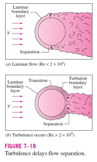
19 At very low upstream velocities (Re 1), the fluid completely wraps around the cylinder. At higher velocities the boundary layer detaches from the surface, forming a separation region behind the cylinder. Flow in the wake region is characterized by periodic vortex formation and low pressures. The nature of the flow across a cylinder or sphere strongly affects the total drag coefficient C D. At low Reynolds numbers (Re<10) friction drag dominate. At high Reynolds numbers (Re>5000) pressure drag dominate. At intermediate Reynolds numbers both pressure and friction drag are significant.
20 Average C D for circular cylinder and sphere Re 1 creeping flow Re 10 separation starts Re 90 vortex shedding starts <Re<10 5 in the boundary layer flow is laminar in the separated region flow is highly turbulent 10 5 <Re<10 6 turbulent flow
21 Effect of Surface Roughness Surface roughness, in general, increases the drag coefficient in turbulent flow. This is especially the case for streamlined bodies. For blunt bodies such as a circular cylinder or sphere, however, an increase in the surface roughness may actually decrease the drag coefficient. This is done by tripping the boundary layer into turbulence at a lower Reynolds number, causing the fluid to close in behind the body, narrowing the wake and reducing pressure drag considerably.
22
23 A: Frontal Area A LD for a cylinder of length L A πd /4 for a sphere

24 Heat Transfer Coefficient Flows across cylinders and spheres, in general, involve flow separation, which is difficult to handle analytically. The local Nusselt number Nu θ around the periphery of a cylinder subjected to cross flow varies considerably. Small θ Nu θ decreases with increasing θ as a result of the thickening of the laminar boundary layer. 80º<θ <90º Nu θ reaches a minimum low Reynolds numbers due to separation in laminar flow high Reynolds numbers transition to turbulent flow. θ >90º laminar flow Nu θ increases with increasing θ due to intense mixing in the separation zone. 90º<θ <140º turbulent flow Nu θ decreases due to the thickening of the boundary layer. θ 140º turbulent flow Nu θ reaches a second minimum due to flow separation point in turbulent flow.
25 Average Heat Transfer Coefficient For flow over a cylinder (Churchill and Bernstein): Nu cyl 1 1/3 58 hd 0.6Re Pr Re / k 1 8,000 + ( 0.4 Pr) 45 (7-35) Re Pr>0. The fluid properties are evaluated at the film temperature [T f (T +T s )/].
26 Flow over a sphere (Whitaker): Nu sph hd 0.4Re 0.06Re Pr μ k + μs 3.5 Re 80, Pr (7-36) The fluid properties in this case are evaluated at the free-stream temperature T B except for μ s, which is evaluated at the surface temperature T s
27 A more compact correlation for flow across cylinders Nu cyl hd m n C Re Pr (7-37) k where n 1 / 3 and the experimentally determined constants C and m are given in Table 7-1. Eq is more accurate, and thus should be preferred in calculations whenever possible.

28 Ex.: An average person generates heat at a rate of 84 W while resting. Assuming one-quarter of this heat is lost from the head and disregarding radiation, determine the average surfacetemp. of the head when it is not covered and is subjected to winds at 10 C and 35 km/h. The head can be approximated as a 30-cm-diameter sphere. Air V 35 km/h T 10 C Head Q 1 W D 0.3 m
29 Properties The properties of air at 1 atm pressure and the free stream temperature of 10 C are (Table A-15) Analysis μ μ C k W/m. C υ Pr m /s kg/m.s kg/m.s [( /3600) m/s] (0.3 m) 5 Re V D υ m /s Nu hd k / 3 [ 0.4 Re Re ] Pr 0.4 μ μ s 1/ 4 1/ / [ 0.4( ) 0.06( ) ](0.7336)
30 h k Nu D W/m. C (344.7) 8.0 W/m. C 0.3 m A s Q πd ha s π (0.3 m) ( T s T ) 0.87 m T s T + Q ha s 10 C + (8.0 W/m (84/4) W. C)(0.87 m ) 1.7 C

31 Flow Across Tube Bank Cross-flow over tube banks is commonly encountered in practice in heat transfer equipment such heat exchangers. In such equipment, one fluid moves through the tubes while the other moves over the tubes in a perpendicular direction. Flow through the tubes can be analyzed by considering flow through a single tube, and multiplying the results by the number of tubes. For flow over the tubes the tubes affect the flow pattern and turbulence level downstream, and thus heat transfer to or from them are altered.


32 Typical arrangement in-line staggered The outer tube diameter D is the characteristic length. The arrangement of the tubes are characterized by the transverse pitch S T, longitudinal pitch S L, and the diagonal pitch S D between tube centers. A 1 S T L, A T (S T -D)L, and A D (S D -D)/L In-line Staggered
33 As the fluid enters the tube bank, the flow area decreases from A 1 S T L to A T (S T -D)L between the tubes, and thus flow velocity increases. In tube banks, the flow characteristics are dominated by the maximum velocity V max. The Reynolds number is defined on the basis of maximum velocity as ρvmaxd VmaxD Re D μ ν (7-39) For in-line arrangement, the maximum velocity occurs at the minimum flow area between the tubes V max S T ST V D (7-40)
34 In staggered arrangement, for S D >(S T +D)/ : for S D <(S T +D)/ : V V max max The nature of flow around a tube in the first row resembles flow over a single tube. The nature of flow around a tube in the second and subsequent rows is very different. The level of turbulence, and thus the heat transfer coefficient, increases with row number. there is no significant change in turbulence level after the first few rows, and thus the heat transfer coefficient remains constant. S T ST S V D T ( S D) D V (7-40) (7-41)

35 Zukauskas has proposed correlations whose general form is Nu hd m n C Re Pr ( Pr Pr ) 0.5 (7-4) k D D s where the values of the constants C, m, and n depend on Reynolds number. The average Nusselt number relations in Table 7 are for tube banks with 16 or more rows. Those relations can also be used for tube banks with N L provided that they are modified as Nu D N, L F Nu (7-43) D The correction factor F values are given in Table 7 3.
/ Note: If T e is not available we have to")
36 Arithmetic mean temp.: T m (T i +T e )/ Note: If T e is not available we have to assume T m, then we must check our assumption
37 A s N πdl N: Total number of tubes N T : # of tubes in transverse plane N L : # of rows NN L x N T Logarithmic mean temp difference: m ρ VN S L T T V: fluid velocity just before entering the tube bank ρ : to be evaluated at T i

 and from equilateral")
38 Pressure drop the pressure drop over tube banks is expressed as: ρvmax P NL f χ f is the friction factor and χ is the correction factor. Δ (7-48) The correction factor (χ) given in the insert is used to account for the effects of deviation from square arrangement (in-line) and from equilateral arrangement (staggered).
39 EX.: Exhaust gases at 1 atm and 300ºC are used to preheat water in an industrial facility by passing them over a bank of tubes through which water is flowing at a rate of 6 kg/s. The mean tube wall temperature is 80ºC. Exhaust gases approach the tube bank in normal direction at 4.5 m/s. The outer diameter of the tubes is.1 cm, and the tubes are arranged in-line with longitudinal and transverse pitches of S L S T 8 cm. There are 16 rows in the flow direction with 8 tubes in each row. Using the properties of air for exhaust gases, determine (a) the rate of heat transfer per unit length of tubes, (b) and pressure drop across the tube bank, and (c) the temperature rise of water flowing through the tubes per unit length of tubes. V4.5 m/s T i 300 C S L T s 80 C S T D
40 Properties: The exit temperature of air, and thus the mean temperature, is not known. We evaluate the air properties at the assumed mean temperature of 50 C (will be checked later) and 1 atm (Table A-15): k W/m-K ρ kg/m3 Cp kj/kg-k Pr μ kg/m-s Prs Pr@ Ts Also, the density of air at the inlet temperature of 300 C (for use in the mass flow rate calculation at the inlet) is ρ i kg/m3. Analysis (a) It is given that D 0.01 m, S L S T 0.08 m, and V 4.5 m/s. V S 0.08 (4.5 m/s) max T S D V T 6.10 m/s Re D ρv max μ D ( kg/m )(6.10 m/s)(0.01m) 5 kg/m s 313
41 From Tabl 7-: Nu D Re D Pr (Pr/ Prs ) 0.7(313) (0.6946) ( / ) Since N L 16: Nu, Nu D N L D h Nu D, D N L k 37.46( W/m C) 73. W/m 0.01 m N N L N T C A s NπDL 18 π(0.01m)(1m) m m m i ρ V( N S L) i T T ( kg/m 3 )(4.5 m/s)(8)(0.08 m)(1m) kg/s T e ( ) exp A sh Ts Ts Ti mc p 80 (80 300) exp (8.445 m )(73. W/m C) (1.773 kg/s)(1033 J/kg C) 37.0 C ( Ts Ti ) ( Ts Te ) (80 300) (80 37) ΔTln C ln[( T T ) /( T T )] ln[(80 300) /(80 37)] s i s e Q ha Δ (73. W/m C)(8.445m )(186.7 C) s T ln 115,45 W
42 (b) For this in-line arrangement tube bank, the friction coefficient corresponding to Re D 313 and S L /D 8/ is, from Fig. 7-7a, f Also, χ 1 for the square arrangements. Then the pressure drop across the tube bank becomes ΔP N L fχ ρv max 16(0.18)(1) ( kg/m 3 )(6.10 m/s) 1 N 1kg m/s 36. Pa (c) The temperature rise of water is Q m water C p, water ΔT water ΔT water m water Q C p, water kw (6 kg/s)(4.18 kj/kg C) 4.6 C Discussion: The arithmetic mean fluid temperature is: (Ti + Te)/ ( )/ 69 C, which is sufficiently close to the assumed value of 50 C. Therefore, there is no need to repeat calculations.
External Forced Convection. Copyright The McGraw-Hill Companies, Inc. Permission required for reproduction or display.
 External Forced Convection Copyright The McGraw-Hill Companies, Inc. Permission required for reproduction or display. Drag and Heat Transfer in External flow Fluid flow over solid bodies is responsible
Chapter 7: External Forced Convection
 Chapter 7: External Forced Convection Yoav Peles Department of Mechanical, Aerospace and Nuclear Engineering Rensselaer Polytechnic Institute Copyright The McGraw-Hill Companies, Inc. Permission required
In Chapter 6 we considered the general and theoretical aspects of forced
 cen58933_ch07.qxd 9/4/2002 12:12 PM Page 367 EXTERNAL FORCED CONVECTION CHAPTER 7 In Chapter 6 we considered the general and theoretical aspects of forced convection, with emphasis on differential formulation
UNIT II CONVECTION HEAT TRANSFER
 UNIT II CONVECTION HEAT TRANSFER Convection is the mode of heat transfer between a surface and a fluid moving over it. The energy transfer in convection is predominately due to the bulk motion of the fluid
External Forced Convection :
 External Forced Convection : Flow over Bluff Objects (Cylinders, Spheres, Packed Beds) and Impinging Jets Chapter 7 Sections 7.4 through 7.8 7.4 The Cylinder in Cross Flow Conditions depend on special
ENGR Heat Transfer II
 ENGR 7901 - Heat Transfer II External Flows 1 Introduction In this chapter we will consider several fundamental flows, namely: the flat plate, the cylinder, the sphere, several other body shapes, and banks
Empirical Co - Relations approach for solving problems of convection 10:06:43
 Empirical Co - Relations approach for solving problems of convection 10:06:43 10:06:44 Empirical Corelations for Free Convection Use T f or T b for getting various properties like Re = VL c / ν β = thermal
Convection Heat Transfer. Introduction
 Convection Heat Transfer Reading Problems 12-1 12-8 12-40, 12-49, 12-68, 12-70, 12-87, 12-98 13-1 13-6 13-39, 13-47, 13-59 14-1 14-4 14-18, 14-24, 14-45, 14-82 Introduction Newton s Law of Cooling Controlling
Chapter 11: Heat Exchangers. Dr Ali Jawarneh Department of Mechanical Engineering Hashemite University
 Chapter 11: Heat Exchangers Dr Ali Jawarneh Department of Mechanical Engineering Hashemite University Objectives When you finish studying this chapter, you should be able to: Recognize numerous types of
Convection Workshop. Academic Resource Center
 Convection Workshop Academic Resource Center Presentation Outline Understanding the concepts Correlations External Convection (Chapter 7) Internal Convection (Chapter 8) Free Convection (Chapter 9) Solving
PHYSICAL MECHANISM OF CONVECTION
 Tue 8:54:24 AM Slide Nr. 0 of 33 Slides PHYSICAL MECHANISM OF CONVECTION Heat transfer through a fluid is by convection in the presence of bulk fluid motion and by conduction in the absence of it. Chapter
Heat Transfer Convection
 Heat ransfer Convection Previous lectures conduction: heat transfer without fluid motion oday (textbook nearly 00 pages) Convection: heat transfer with fluid motion Research methods different Natural Convection
Chapter 3 NATURAL CONVECTION
 Fundamentals of Thermal-Fluid Sciences, 3rd Edition Yunus A. Cengel, Robert H. Turner, John M. Cimbala McGraw-Hill, 2008 Chapter 3 NATURAL CONVECTION Mehmet Kanoglu Copyright The McGraw-Hill Companies,
Convective Mass Transfer
 Convective Mass Transfer Definition of convective mass transfer: The transport of material between a boundary surface and a moving fluid or between two immiscible moving fluids separated by a mobile interface
INSTRUCTOR: PM DR MAZLAN ABDUL WAHID
 SMJ 4463: HEAT TRANSFER INSTRUCTOR: PM ABDUL WAHID http://www.fkm.utm.my/~mazlan TEXT: Introduction to Heat Transfer by Incropera, DeWitt, Bergman, Lavine 6 th Edition, John Wiley and Sons Chapter 7 External
Heat Transfer F12-ENG Lab #4 Forced convection School of Engineering, UC Merced.
 1 Heat Transfer F12-ENG-135 - Lab #4 Forced convection School of Engineering, UC Merced. October 23, 2012 1 General purpose of the Laboratory To gain a physical understanding of the behavior of the average
Chapter 3: Steady Heat Conduction. Dr Ali Jawarneh Department of Mechanical Engineering Hashemite University
 Chapter 3: Steady Heat Conduction Dr Ali Jawarneh Department of Mechanical Engineering Hashemite University Objectives When you finish studying this chapter, you should be able to: Understand the concept
If there is convective heat transfer from outer surface to fluid maintained at T W.
 Heat Transfer 1. What are the different modes of heat transfer? Explain with examples. 2. State Fourier s Law of heat conduction? Write some of their applications. 3. State the effect of variation of temperature
ME 331 Homework Assignment #6
 ME 33 Homework Assignment #6 Problem Statement: ater at 30 o C flows through a long.85 cm diameter tube at a mass flow rate of 0.020 kg/s. Find: The mean velocity (u m ), maximum velocity (u MAX ), and
Chapter 4: Transient Heat Conduction. Dr Ali Jawarneh Department of Mechanical Engineering Hashemite University
 Chapter 4: Transient Heat Conduction Dr Ali Jawarneh Department of Mechanical Engineering Hashemite University Objectives When you finish studying this chapter, you should be able to: Assess when the spatial
Internal Forced Convection. Copyright The McGraw-Hill Companies, Inc. Permission required for reproduction or display.
 Internal Forced Convection Copyright The McGraw-Hill Companies, Inc. Permission required for reproduction or display. Introduction Pipe circular cross section. Duct noncircular cross section. Tubes small-diameter
Forced Convection Around Obstacles
 Chapter 4 Forced Convection Around Obstacles 4.1. Description of the flow This chapter is devoted to heat transfer on bodies immersed in a stream. We consider a solid characterized by the length scale
6 Empirical and Practical
 6 Empirical and Practical Forced-Convection Relations for Heat Transfer CHAPTER 6-1 INTRODUCTION The discussion and analyses of Chapter 5 have shown how forced-convection heat transfer may be calculated
In order to optimize the shell and coil heat exchanger design using the model presented in Chapter
 1 CHAPTER FOUR The Detailed Model In order to optimize the shell and coil heat exchanger design using the model presented in Chapter 3, one would have to build several heat exchanger prototypes, and then
ELEC9712 High Voltage Systems. 1.2 Heat transfer from electrical equipment
 ELEC9712 High Voltage Systems 1.2 Heat transfer from electrical equipment The basic equation governing heat transfer in an item of electrical equipment is the following incremental balance equation, with
Outlines. simple relations of fluid dynamics Boundary layer analysis. Important for basic understanding of convection heat transfer
 Forced Convection Outlines To examine the methods of calculating convection heat transfer (particularly, the ways of predicting the value of convection heat transfer coefficient, h) Convection heat transfer
ECE309 INTRODUCTION TO THERMODYNAMICS & HEAT TRANSFER. 3 August 2004
 ECE309 INTRODUCTION TO THERMODYNAMICS & HEAT TRANSFER 3 August 004 Final Examination R. Culham This is a 3 hour, closed-book examination. You are permitted to use one 8.5 in. in. crib sheet (both sides),
PROBLEM 7.2 1/3. (b) The local convection coefficient, Eq. 7.23, and heat flux at x = L are 1/2 1/3
 The local convection coefficient, Eq. 7.23, and heat flux at x = L are 1/2 1/3") PROBLEM 7. KNOWN: Temperature and velocity of engine oil. Temperature and length of flat plate. FIND: (a) Velocity and thermal boundary layer thickness at trailing edge, (b) Heat flux and surface shear
PROBLEM 7. KNOWN: Temperature and velocity of engine oil. Temperature and length of flat plate. FIND: (a) Velocity and thermal boundary layer thickness at trailing edge, (b) Heat flux and surface shear
Lecture-4. Flow Past Immersed Bodies
 Lecture-4 Flow Past Immersed Bodies Learning objectives After completing this lecture, you should be able to: Identify and discuss the features of external flow Explain the fundamental characteristics
Convection. forced convection when the flow is caused by external means, such as by a fan, a pump, or atmospheric winds.
 Convection The convection heat transfer mode is comprised of two mechanisms. In addition to energy transfer due to random molecular motion (diffusion), energy is also transferred by the bulk, or macroscopic,
FORMULA SHEET. General formulas:
 FORMULA SHEET You may use this formula sheet during the Advanced Transport Phenomena course and it should contain all formulas you need during this course. Note that the weeks are numbered from 1.1 to
OUTCOME 2 - TUTORIAL 1
 Unit 4: Heat Transfer and Combustion Unit code: K/60/44 QCF level: 5 Credit value: 5 OUTCOME - TUTORIAL Heat transfer coefficients Dimensional analysis: dimensionless groups; Reynolds, Nusselt, Prandtl,
HEAT TRANSFER BY CONVECTION. Dr. Şaziye Balku 1
 HEAT TRANSFER BY CONVECTION Dr. Şaziye Balku 1 CONDUCTION Mechanism of heat transfer through a solid or fluid in the absence any fluid motion. CONVECTION Mechanism of heat transfer through a fluid in the
True/False. Circle the correct answer. (1pt each, 7pts total) 3. Radiation doesn t occur in materials that are transparent such as gases.
 3. Radiation doesn t occur in materials that are transparent such as gases.") ME 323 Sample Final Exam. 120pts total True/False. Circle the correct answer. (1pt each, 7pts total) 1. A solid angle of 2π steradians defines a hemispherical shell. T F 2. The Earth irradiates the Sun.
ME 323 Sample Final Exam. 120pts total True/False. Circle the correct answer. (1pt each, 7pts total) 1. A solid angle of 2π steradians defines a hemispherical shell. T F 2. The Earth irradiates the Sun.
Principles of Convection
 Principles of Convection Point Conduction & convection are similar both require the presence of a material medium. But convection requires the presence of fluid motion. Heat transfer through the: Solid
Autumn 2005 THERMODYNAMICS. Time: 3 Hours
 CORK INSTITUTE OF TECHNOOGY Bachelor of Engineering (Honours) in Mechanical Engineering Stage 3 (Bachelor of Engineering in Mechanical Engineering Stage 3) (NFQ evel 8) Autumn 2005 THERMODYNAMICS Time:
Friction Factors and Drag Coefficients
 Levicky 1 Friction Factors and Drag Coefficients Several equations that we have seen have included terms to represent dissipation of energy due to the viscous nature of fluid flow. For example, in the
1. Nusselt number and Biot number are computed in a similar manner (=hd/k). What are the differences between them? When and why are each of them used?
. What are the differences between them? When and why are each of them used?") 1. Nusselt number and Biot number are computed in a similar manner (=hd/k). What are the differences between them? When and why are each of them used?. During unsteady state heat transfer, can the temperature
1. Nusselt number and Biot number are computed in a similar manner (=hd/k). What are the differences between them? When and why are each of them used?. During unsteady state heat transfer, can the temperature
TankExampleNov2016. Table of contents. Layout
 Table of contents Task... 2 Calculation of heat loss of storage tanks... 3 Properties ambient air Properties of air... 7 Heat transfer outside, roof Heat transfer in flow past a plane wall... 8 Properties
Introduction to Heat and Mass Transfer. Week 14
 Introduction to Heat and Mass Transfer Week 14 Next Topic Internal Flow» Velocity Boundary Layer Development» Thermal Boundary Layer Development» Energy Balance Velocity Boundary Layer Development Velocity
Fluids. Fluids in Motion or Fluid Dynamics
 Fluids Fluids in Motion or Fluid Dynamics Resources: Serway - Chapter 9: 9.7-9.8 Physics B Lesson 3: Fluid Flow Continuity Physics B Lesson 4: Bernoulli's Equation MIT - 8: Hydrostatics, Archimedes' Principle,
PHYSICAL MECHANISM OF NATURAL CONVECTION
 1 NATURAL CONVECTION In this chapter, we consider natural convection, where any fluid motion occurs by natural means such as buoyancy. The fluid motion in forced convection is quite noticeable, since a
Fundamental Concepts of Convection : Flow and Thermal Considerations. Chapter Six and Appendix D Sections 6.1 through 6.8 and D.1 through D.
 Fundamental Concepts of Convection : Flow and Thermal Considerations Chapter Six and Appendix D Sections 6.1 through 6.8 and D.1 through D.3 6.1 Boundary Layers: Physical Features Velocity Boundary Layer
The average velocity of water in the tube and the Reynolds number are Hot R-134a
 hater 0:, 8, 4, 47, 50, 5, 55, 7, 75, 77, 8 and 85. 0- Refrigerant-4a is cooled by water a double-ie heat exchanger. he overall heat transfer coefficient is to be determed. Assumtions he thermal resistance
Level 7 Post Graduate Diploma in Engineering Heat and mass transfer
 9210-221 Level 7 Post Graduate Diploma in Engineering Heat and mass transfer 0 You should have the following for this examination one answer book non programmable calculator pen, pencil, drawing instruments
CHAPTER 4 BOUNDARY LAYER FLOW APPLICATION TO EXTERNAL FLOW
 CHAPTER 4 BOUNDARY LAYER FLOW APPLICATION TO EXTERNAL FLOW 4.1 Introduction Boundary layer concept (Prandtl 1904): Eliminate selected terms in the governing equations Two key questions (1) What are the
PROBLEM 8.3 ( ) p = kg m 1m s m 1000 m = kg s m = bar < P = N m 0.25 m 4 1m s = 1418 N m s = 1.
 p = kg m 1m s m 1000 m = kg s m = bar < P = N m 0.25 m 4 1m s = 1418 N m s = 1.") PROBLEM 8.3 KNOWN: Temperature and velocity of water flow in a pipe of prescribed dimensions. FIND: Pressure drop and pump power requirement for (a) a smooth pipe, (b) a cast iron pipe with a clean surface,
PROBLEM 8.3 KNOWN: Temperature and velocity of water flow in a pipe of prescribed dimensions. FIND: Pressure drop and pump power requirement for (a) a smooth pipe, (b) a cast iron pipe with a clean surface,
The Effect of Solid and Perforated Pin Fin on the Heat Transfer Performance of Finned Tube Heat Exchanger
 International Journal of Energy Engineering 2018, 8(1): 1-11 DOI: 10.5923/j.ijee.20180801.01 The Effect of Solid and Perforated Pin Fin on the Heat Transfer Performance of Finned Tube Heat Exchanger Nabil
Review on Thermal Performance of cross Flow Heat Exchanger Using Non-Circular Shape of Tubes
 Review on Thermal Performance of cross Flow Heat Exchanger Using Non-Circular Shape of Tubes 1 Snehal A. Powar, 2 Ashish R. Wankhade, 3 Neelam Gohel Email: 1 snehal.311991@gmail.com, 2 wankhade_ashish@ymail.com,
Fall 2014 Qualifying Exam Thermodynamics Closed Book
 Fall 2014 Qualifying Exam Thermodynamics Closed Book Saturated ammonia vapor at 200 O F flows through a 0.250 in diameter tube. The ammonia passes through a small orifice causing the pressure to drop very
TUBE BANKS TEST PROBLEMS
 TUBE BANKS TEST PROBLEMS The non-proprietary tests used to validate INSTED analysis of flow and heat transfer over tube banks are presented in this section. You may need to consult the original sources
Liquid or gas flow through pipes or ducts is commonly used in heating and
 cen58933_ch08.qxd 9/4/2002 11:29 AM Page 419 INTERNAL FORCED CONVECTION CHAPTER 8 Liquid or gas flow through pipes or ducts is commonly used in heating and cooling applications. The fluid in such applications
Problem 4.3. Problem 4.4
 Problem 4.3 Problem 4.4 Problem 4.5 Problem 4.6 Problem 4.7 This is forced convection flow over a streamlined body. Viscous (velocity) boundary layer approximations can be made if the Reynolds number Re
8.1 Technically Feasible Design of a Heat Exchanger
 328 Technically Feasible Design Case Studies T 2 q 2 ρ 2 C p2 T F q ρ C p T q ρ C p T 2F q 2 ρ 2 C p2 Figure 3.5. Countercurrent double-pipe exchanger. 8. Technically Feasible Design of a Heat Exchanger
Summary of Dimensionless Numbers of Fluid Mechanics and Heat Transfer
 1. Nusselt number Summary of Dimensionless Numbers of Fluid Mechanics and Heat Transfer Average Nusselt number: convective heat transfer Nu L = conductive heat transfer = hl where L is the characteristic
6. Laminar and turbulent boundary layers
 6. Laminar and turbulent boundary layers John Richard Thome 8 avril 2008 John Richard Thome (LTCM - SGM - EPFL) Heat transfer - Convection 8 avril 2008 1 / 34 6.1 Some introductory ideas Figure 6.1 A boundary
CEE 3310 External Flows (Boundary Layers & Drag), /2 f = 0.664
, /2 f = 0.664") CEE 3310 External Flows (Boundary Layers & Drag), 2010 161 7.12 Review Boundary layer equations u u x + v u y = u ν 2 y 2 Blasius Solution δ x = 5.0 and c Rex 1/2 f = 0.664 Re 1/2 x within 10% of Von Kármán
CEE 3310 External Flows (Boundary Layers & Drag), 2010 161 7.12 Review Boundary layer equations u u x + v u y = u ν 2 y 2 Blasius Solution δ x = 5.0 and c Rex 1/2 f = 0.664 Re 1/2 x within 10% of Von Kármán
Numerical Investigation of Thermal Performance in Cross Flow Around Square Array of Circular Cylinders
 Numerical Investigation of Thermal Performance in Cross Flow Around Square Array of Circular Cylinders A. Jugal M. Panchal, B. A M Lakdawala 2 A. M. Tech student, Mechanical Engineering Department, Institute
Figure 3: Problem 7. (a) 0.9 m (b) 1.8 m (c) 2.7 m (d) 3.6 m
 0.9 m (b) 1.8 m (c) 2.7 m (d) 3.6 m") 1. For the manometer shown in figure 1, if the absolute pressure at point A is 1.013 10 5 Pa, the absolute pressure at point B is (ρ water =10 3 kg/m 3, ρ Hg =13.56 10 3 kg/m 3, ρ oil = 800kg/m 3 ): (a)
1. For the manometer shown in figure 1, if the absolute pressure at point A is 1.013 10 5 Pa, the absolute pressure at point B is (ρ water =10 3 kg/m 3, ρ Hg =13.56 10 3 kg/m 3, ρ oil = 800kg/m 3 ): (a)
DESIGN OF A SHELL AND TUBE HEAT EXCHANGER
 DESIGN OF A SHELL AND TUBE HEAT EXCHANGER Swarnotpal Kashyap Department of Chemical Engineering, IIT Guwahati, Assam, India 781039 ABSTRACT Often, in process industries the feed stream has to be preheated
CEE 3310 External Flows (Boundary Layers & Drag, Nov. 14, Re 0.5 x x 1/2. Re 1/2
 CEE 3310 External Flows (Boundary Layers & Drag, Nov. 14, 2016 159 7.10 Review Momentum integral equation τ w = ρu 2 dθ dx Von Kármán assumed and found δ x = 5.5 Rex 0.5 u(x, y) U = 2y δ y2 δ 2 δ = 5.5
PROBLEM ρ v (kg/m 3 ) ANALYSIS: The critical heat flux can be estimated by Eq with C = 0.
 ANALYSIS: The critical heat flux can be estimated by Eq with C = 0.") PROBLEM 10.10 KNOWN: Fluids at 1 atm: mercury, ethanol, R-14a. FIND: Critical heat flux; compare with value for water also at 1 atm. ASSUMPTIONS: (1) Steady-state conditions, () Nucleate pool boiling.
PROBLEM 10.10 KNOWN: Fluids at 1 atm: mercury, ethanol, R-14a. FIND: Critical heat flux; compare with value for water also at 1 atm. ASSUMPTIONS: (1) Steady-state conditions, () Nucleate pool boiling.
PROBLEM Node 5: ( ) ( ) ( ) ( )
 ( ) ( ) ( )") PROBLEM 4.78 KNOWN: Nodal network and boundary conditions for a water-cooled cold plate. FIND: (a) Steady-state temperature distribution for prescribed conditions, (b) Means by which operation may be extended
PROBLEM 4.78 KNOWN: Nodal network and boundary conditions for a water-cooled cold plate. FIND: (a) Steady-state temperature distribution for prescribed conditions, (b) Means by which operation may be extended
Chapter 9 NATURAL CONVECTION
 Heat and Mass Transfer: Fundamentals & Applications Fourth Edition in SI Units Yunus A. Cengel, Afshin J. Ghajar McGraw-Hill, 2011 Chapter 9 NATURAL CONVECTION PM Dr Mazlan Abdul Wahid Universiti Teknologi
CEE 3310 External Flows (Boundary Layers & Drag, Nov. 12, Re 0.5 x x 1/2. Re 1/2
 CEE 3310 External Flows (Boundary Layers & Drag, Nov. 12, 2018 155 7.11 Review Momentum integral equation τ w = ρu 2 dθ dx Von Kármán assumed and found and δ x = 5.5 Rex 0.5 u(x, y) U = 2y δ y2 δ 2 δ =
Modeling of Fluid Flow and Heat Transfer for Optimization of Pin-Fin Heat Sinks
 Modeling of Fluid Flow and Heat Transfer for Optimization of Pin-Fin Heat Sinks by Waqar Ahmed Khan Athesis presented to the University of Waterloo in fulfillment of the thesis requirement for the degree
Tutorial 1. Where Nu=(hl/k); Reynolds number Re=(Vlρ/µ) and Prandtl number Pr=(µCp/k)
; Reynolds number Re=(Vlρ/µ) and Prandtl number Pr=(µCp/k)") Tutorial 1 1. Explain in detail the mechanism of forced convection. Show by dimensional analysis (Rayleigh method) that data for forced convection may be correlated by an equation of the form Nu = φ (Re,
Tutorial 1 1. Explain in detail the mechanism of forced convection. Show by dimensional analysis (Rayleigh method) that data for forced convection may be correlated by an equation of the form Nu = φ (Re,
11. Advanced Radiation
 . Advanced adiation. Gray Surfaces The gray surface is a medium whose monochromatic emissivity ( λ does not vary with wavelength. The monochromatic emissivity is defined as the ratio of the monochromatic
TOPIC 2 [A] STEADY STATE HEAT CONDUCTION
![TOPIC 2 [A] STEADY STATE HEAT CONDUCTION](/thumbs/96/128741039.jpg "TOPIC 2 [A] STEADY STATE HEAT CONDUCTION") TOPIC 2 [A] STEADY STATE HEAT CONDUCTION CLASS TUTORIAL 1. The walls of a refrigerated truck consist of 1.2 mm thick steel sheet (k=18 W/m-K) at the outer surface, 22 mm thick cork (k=0.04 W/m-K) on the
TOPIC 2 [A] STEADY STATE HEAT CONDUCTION CLASS TUTORIAL 1. The walls of a refrigerated truck consist of 1.2 mm thick steel sheet (k=18 W/m-K) at the outer surface, 22 mm thick cork (k=0.04 W/m-K) on the
AEROSPACE ENGINEERING DEPARTMENT. Second Year - Second Term ( ) Fluid Mechanics & Gas Dynamics
 Fluid Mechanics & Gas Dynamics") AEROSPACE ENGINEERING DEPARTMENT Second Year - Second Term (2008-2009) Fluid Mechanics & Gas Dynamics Similitude,Dimensional Analysis &Modeling (1) [7.2R*] Some common variables in fluid mechanics include:
AEROSPACE ENGINEERING DEPARTMENT Second Year - Second Term (2008-2009) Fluid Mechanics & Gas Dynamics Similitude,Dimensional Analysis &Modeling (1) [7.2R*] Some common variables in fluid mechanics include:
MYcsvtu Notes HEAT TRANSFER BY CONVECTION
 www.mycsvtunotes.in HEAT TRANSFER BY CONVECTION CONDUCTION Mechanism of heat transfer through a solid or fluid in the absence any fluid motion. CONVECTION Mechanism of heat transfer through a fluid in
Principles of Food and Bioprocess Engineering (FS 231) Problems on Heat Transfer
 Problems on Heat Transfer") Principles of Food and Bioprocess Engineering (FS 1) Problems on Heat Transfer 1. What is the thermal conductivity of a material 8 cm thick if the temperature at one end of the product is 0 C and the temperature
Principles of Food and Bioprocess Engineering (FS 1) Problems on Heat Transfer 1. What is the thermal conductivity of a material 8 cm thick if the temperature at one end of the product is 0 C and the temperature
Coolant. Circuits Chip
 1) A square isothermal chip is of width w=5 mm on a side and is mounted in a subtrate such that its side and back surfaces are well insulated, while the front surface is exposed to the flow of a coolant
 UNIT IV BOUNDARY LAYER AND FLOW THROUGH PIPES Definition of boundary layer Thickness and classification Displacement and momentum thickness Development of laminar and turbulent flows in circular pipes
Numerical study of forced convection around heated horizontal triangular ducts
 Advanced Computational Methods and Experiments in Heat Transfer XI 0 Numerical study of forced convection around heated horizontal triangular ducts O. Zeitoun, M. E. Ali & A. Nuhait King Saud University,
Examination Heat Transfer
 Examination Heat Transfer code: 4B680 date: June 13, 2008 time: 14.00-17.00 Note: There are 4 questions in total. The first one consists of independent subquestions. If possible and necessary, guide numbers
Analysis of Temperature loss of Hot Metal during Hot Rolling P rocess at Steel Plant
 International OPEN ACCESS Journal Of Modern Engineering Research (IJMER) Analysis of Temperature loss of Hot Metal during Hot Rolling P rocess at Steel Plant.. Anantha irthan 1, S. Sathurtha Mourian 2,
MECHANISM BEHIND FREE /NATURAL CONVECTION
 CONVECTIVE HEAT TRANSFER By: Prof K. M. Joshi, Assi. Professor, MED, SSAS Institute of Technology, Surat. MECHANISM BEHIND FREE /NATURAL CONVECTION The stagnate layer of fluid in immediate vicinity of
7.2 Sublimation. The following assumptions are made in order to solve the problem: Sublimation Over a Flat Plate in a Parallel Flow
 7..1 Sublimation Over a Flat Plate in a Parallel Flow The following assumptions are made in order to solve the problem: 1.. 3. The flat plate is very thin and so the thermal resistance along the flat plate
23 1 TYPES OF HEAT EXCHANGERS
 cen5426_ch23.qxd /26/04 9:42 AM Page 032 032 FUNDAMENTALS OF THERMAL-FLUID SCIENCES 23 TYPES OF HEAT EXCHANGERS Different heat transfer applications require different types of hardware different configurations
Numerical Investigation of the Fluid Flow around and Past a Circular Cylinder by Ansys Simulation
 , pp.49-58 http://dx.doi.org/10.1457/ijast.016.9.06 Numerical Investigation of the Fluid Flow around and Past a Circular Cylinder by Ansys Simulation Mojtaba Daneshi Department of Mechanical Engineering,
HEAT TRANSFER. Mechanisms of Heat Transfer: (1) Conduction
 Conduction") HEAT TRANSFER Mechanisms of Heat Transfer: (1) Conduction where Q is the amount of heat, Btu, transferred in time t, h k is the thermal conductivity, Btu/[h ft 2 ( o F/ft)] A is the area of heat transfer
HEAT TRANSFER Mechanisms of Heat Transfer: (1) Conduction where Q is the amount of heat, Btu, transferred in time t, h k is the thermal conductivity, Btu/[h ft 2 ( o F/ft)] A is the area of heat transfer
Introduction to Heat and Mass Transfer. Week 14
 Introduction to Heat and Mass Transfer Week 14 HW # 7 prob. 2 Hot water at 50C flows through a steel pipe (thermal conductivity 14 W/m-K) of 100 mm outside diameter and 8 mm wall thickness. During winter,
Principles of Food and Bioprocess Engineering (FS 231) Exam 2 Part A -- Closed Book (50 points)
 Exam 2 Part A -- Closed Book (50 points)") Principles of Food and Bioprocess Engineering (FS 231) Exam 2 Part A -- Closed Book (50 points) 1. Are the following statements true or false? (20 points) a. Thermal conductivity of a substance is a measure
Principles of Food and Bioprocess Engineering (FS 231) Exam 2 Part A -- Closed Book (50 points) 1. Are the following statements true or false? (20 points) a. Thermal conductivity of a substance is a measure
Parallel Plate Heat Exchanger
 Parallel Plate Heat Exchanger Parallel Plate Heat Exchangers are use in a number of thermal processing applications. The characteristics are that the fluids flow in the narrow gap, between two parallel
ENERGY PERFORMANCE IMPROVEMENT, FLOW BEHAVIOR AND HEAT TRANSFER INVESTIGATION IN A CIRCULAR TUBE WITH V-DOWNSTREAM DISCRETE BAFFLES
 Journal of Mathematics and Statistics 9 (4): 339-348, 2013 ISSN: 1549-3644 2013 doi:10.3844/jmssp.2013.339.348 Published Online 9 (4) 2013 (http://www.thescipub.com/jmss.toc) ENERGY PERFORMANCE IMPROVEMENT,
Analysis, Design and Fabrication of Forced Convection Apparatus
 Analysis, Design and Fabrication of Forced Convection Apparatus Shajan K. Thomas 1, Vishnukumar C M 2, Vishnu C J 3, Alex Baby 4 Assistant Professor, Dept. of Mechanical Engineering, Toc H Institute of
A Numerical Study of Forced Convection Heat Transfer for Staggered Tube Banks in Cross-Flow
 A Numerical Study of Forced Convection Heat Transfer for Staggered Tube Banks in Cross-Flow T. A. Tahseen 1, M. Ishak 1,2 and M. M. Rahman 1,2 1 Faculty of Mechanical Engineering, University Malaysia Pahang
HEAT TRANSFER BY CONVECTION AND CONDUCTION FROM THE FLUID MOVING AT SOLID WALLS
 HEAT TRANSFER BY CONVECTION AND CONDUCTION FROM THE FLUID MOVING AT SOLID WALLS Associate Professor Ph.D. Amado George STEFAN, Lt.Eng., doctoral student Constantin NISTOR MILITARY TECHNICAL ACADEMY Abstract.
Overall Heat Transfer Coefficient
 Overall Heat Transfer Coefficient A heat exchanger typically involves two flowing fluids separated by a solid wall. Heat is first transferred from the hot fluid to the wall by convection, through the wall
CHME 302 CHEMICAL ENGINEERING LABOATORY-I EXPERIMENT 302-V FREE AND FORCED CONVECTION
 CHME 302 CHEMICAL ENGINEERING LABOATORY-I EXPERIMENT 302-V FREE AND FORCED CONVECTION OBJECTIVE The objective of the experiment is to compare the heat transfer characteristics of free and forced convection.
CONVECTIVE HEAT TRANSFER
 CONVECTIVE HEAT TRANSFER Mohammad Goharkhah Department of Mechanical Engineering, Sahand Unversity of Technology, Tabriz, Iran CHAPTER 4 HEAT TRANSFER IN CHANNEL FLOW BASIC CONCEPTS BASIC CONCEPTS Laminar
ENG Heat Transfer II 1. 1 Forced Convection: External Flows Flow Over Flat Surfaces... 4
 ENG7901 - Heat Transfer II 1 Contents 1 Forced Convection: External Flows 4 1.1 Flow Over Flat Surfaces............................. 4 1.1.1 Non-Dimensional form of the Equations of Motion.......... 4
FINITE ELEMENT ANALYSIS OF MIXED CONVECTION HEAT TRANSFER ENHANCEMENT OF A HEATED SQUARE HOLLOW CYLINDER IN A LID-DRIVEN RECTANGULAR ENCLOSURE
 Proceedings of the International Conference on Mechanical Engineering 2011 (ICME2011) 18-20 December 2011, Dhaka, Bangladesh ICME11-TH-014 FINITE ELEMENT ANALYSIS OF MIXED CONVECTION HEAT TRANSFER ENHANCEMENT
Heat Transfer Enhancement Through Perforated Fin
 IOSR Journal of Mechanical and Civil Engineering (IOSR-JMCE) e-issn: 2278-1684,p-ISSN: 2320-334X PP. 72-78 www.iosrjournals.org Heat Transfer Enhancement Through Perforated Fin Noaman Salam, Khan Rahmatullah,
Ben Wolfe 11/3/14. Figure 1: Theoretical diagram showing the each step of heat loss.
 Condenser Analysis Water Cooled Model: For this condenser design there will be a coil of stainless steel tubing suspended in a bath of cold water. The cold water will be stationary and begin at an ambient
Analysis of Heat Transfer in Pipe with Twisted Tape Inserts
 Proceedings of the 2 nd International Conference on Fluid Flow, Heat and Mass Transfer Ottawa, Ontario, Canada, April 30 May 1, 2015 Paper No. 143 Analysis of Heat Transfer in Pipe with Twisted Tape Inserts
Chapter 7: Natural Convection
 7-1 Introduction 7- The Grashof Number 7-3 Natural Convection over Surfaces 7-4 Natural Convection Inside Enclosures 7-5 Similarity Solution 7-6 Integral Method 7-7 Combined Natural and Forced Convection
WTS Table of contents. Layout
 Table of contents Thermal and hydraulic design of shell and tube heat exchangers... 2 Tube sheet data... 4 Properties of Water and Steam... 6 Properties of Water and Steam... 7 Heat transfer in pipe flow...
University of Rome Tor Vergata
 University of Rome Tor Vergata Faculty of Engineering Department of Industrial Engineering THERMODYNAMIC AND HEAT TRANSFER HEAT TRANSFER dr. G. Bovesecchi gianluigi.bovesecchi@gmail.com 06-7259-727 (7249)