Chapter 8 Optical Interferometry
|
|
|
- Bonnie Thompson
- 6 years ago
- Views:
Transcription
1 Chapter 8 Optical Interferometry Lecture Notes for Modern Optics based on Pedrotti & Pedrotti & Pedrotti Instructor: Nayer Eradat Spring 009 4/0/009 Optical Interferometry 1
2 Optical interferometry Interferometer is an instrument design to exploit the interference of light and fringe patternsthat that results from the optical path difference. Interferometers are extended to acoustic and radio waves as well. Here we will explore two kinds 1) Michelson MorleyInterferometer, Morley a two beam, amplitude divisiondevice. device. ) Fabry Perot interferometer a multiple beam, amplitude division device 4/0/009 Optical Interferometry
3 The Michelson interferometer (1881) Used in applications such as proving special theory of relativity, measuring hyperfine structure in line spectra, tidal effect of the moon on the earth. Principle i of operation is shown in the graph. In the graph of the interferometer the path difference between the beams traveling along the two perpendicular paths is: Δ = beam with respect to the optical axis. For normal beam θ = 0 Δ p = d = m d = m for m= 0,1,,3,... will form constructive interference and will repeat every / so long as d < L c separation stays smaller than the coherence length. p d cos θ (see the fig. b) where θ measures the inclination of the The device has two optical axis at right angle Movable mirror Compensator Beam splitter Fixed mirror 4/0/009 Optical Interferometry 3
4 Fringe analysis of Michelson interferometer Now the optical system is equivalent of the plane air film and the fringes of equal inclination are formed and can be viewed dby looking through hthe path h4 or using a telescope in that path. Fringes are made up of concentric circles centered around the optical axis with intensity of I=4I0 cos δ π where the phase difference is δ = kδ= Δ and Δ=Δ p +Δr Here we have a relative π phase shift between the two beams because the i reflection coefficient from two sides of the mirror differs by 1 = e π 1 Δ=Δ p +Δ r = dcosθ + = m+ dcos θ = m, m= 0,1,,... for dark fringes. d d The center fringe is dark. For the normal rays at the center d = m and m max = is order of central dark fringe and outer fringes have lower orders. We invert the fringe order for convenience d d by interoducing another integer p= mmax m= m p = d m p = d 1 cos θ where p=0,1,,3,.. dark fringes ( ) Now the central fring's order is zero. When optical path difference is decreasing the fringes move inward and disappear at the center. When optical path difference is increasing the fringes originate at the center and move outward. 4/0/009 Optical Interferometry 4
5 Fringe counting with Michelson interferometer Wavelength and distance measurement When optical path difference is decreasing the fringes move inward and disappear at the center. When optical path difference is increasing the fringes originate at the center and move outward A smaller mirror spaceing leads to an increase in angular separation Δθ for a given fringe interval. dcos θ = m, m= 0,1,,... for dark fringes. Δm d sin θ Δ θ = Δ m Δ θ = Differenciate θ with respect to m d sinθ this means for a smaller optical path difference the fringes are more widely separated. When d = / ( standing waves form ) then cos θ = m the entire field encompasses one fringe or m max =1. d For a mirror translation Δ d the number of fringes passing the center (cosθ = 1 and m= ) is Δ m = Δd in all of these senarios is constant and we are playing with finge number and d. This suggests an experimental method to measure small mirror movements with a known or measure when Δd is known. 4/0/009 Optical Interferometry 5
6 Applications of the Michelson interferometer 1) Measurement of thin film thickness ) Measurement of index of rfraction of a gass filled in a cell of length L placed in one arm of the interferometer. The fringe count Δm is done as the gas is evacuated fromt the cell. The optical path difference is: Δ d = nl- L= L( n 1) = Δm n= Δ m+ 1 L 3) Measurement of temperature of a gas or index change as a function of temperature. You need ( ) to know T = f n for the mate rial to use it. 4) Determination of the wavelength difference between two closely spaced spectral lines and ' or ν and ν' used in the lab to measure the difference between the wavelengths of the sodium yellow lines. Two kinds of fringes can be observed with iththe Michelson interferometer. t 1) when the mirrors are absolutely perpendicular to each other virtual fringes of equal inclination are observed. ) When the mirors are not quite perpendicular ( small deviation ), an air wedge appears between the mirrors and fringes of equal thickness may form localized at the mirrors that appear as straight lines parallel to the intersection of the two mirrors. For large deviations the fringes appear as hyperbolic curves. 4/0/009 Optical Interferometry 6
7 Variations of the Michelson InterferometerTwyman Green Testing of a prism and lens for variations in their index of refraction or surface imperfections. Point source with a collimating lens Fringes of equal thickness (parallel lines) appear that show imperfections of optical systems Fringes boost interferometer resolution A recent article on increasing resolution of the measurements by interferometry 4/0/009 Optical Interferometry 7


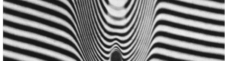
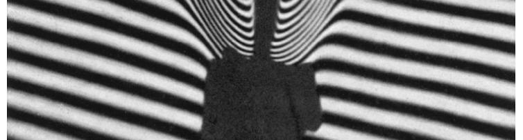
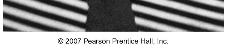
8 Fringes of equal thickness in neighborhood of a candle by Michelson Interferometer 4/0/009 Optical Interferometry 8


9 Mach Zehnder Interferometer Used in aerodynamic research. It uses two beamand and amplitude splitting. Advantage over Michelson interferometer is possibility of making fringes at the object of study so that both can be photographed together. Test Chamber Identical Chamber 4/0/009 Optical Interferometry 9
10 The Fabry Perot Interferometer The fabry-perot interferometer is composed of two semi-transparent parallel plates. Very simple in structure but a very precise measurement tool. The interference pattern is composed of superposition of the multiple beams of transmitted and reflected light. Applications: precision wavelength measurements, hyperfine spectral structures,.measuring refractive indices of gasses, calibration of the standard meter in terms of wavelength. The interferometer is composed of the inner surfaces of the cavity mirrors that usually polished to /50 and coated with silver or aluminium layer ~50nm. Outer surfaces are cut at small angle so that reflection from them does not interfere. When the mirror spacing is fixed the cavity is called etalon. The beam from source S generates multiple cohernt beams in the interferometer the emerging rays are brought together at P. The path difference between the succesive beams is Δ = ndcos θ, for air n = 1 p f i f Δ r = π or no effect on the interference. The condition for bright fringes is dcosθ = m i The fringe pattern, concentric rings, are the fringes of equal inclination. Cavity 4/0/009 Optical Interferometry 10
 Point source and a variable plate spacing. A detector records intensity as a function of the plate spacing. With a laser sources the lenses are not needed.")
11 Different arrangements of the Fabry Perot interferometer a) Extended source and a fixed plate spacing. Circular fringe pattern. b) Point source and a variable plate spacing. A detector records intensity as a function of the plate spacing. With a laser sources the lenses are not needed. 4/0/009 Optical Interferometry 11
12 Fabry Perot transmission: the Airy function Goal: calculating the irradiance transmitted through a Fabry-Perot interferometer. Two identical mirrors separated by a distance d that have real reflection and transmission coefficients r, t and no absorption so r + t = 1. Cavity roundtrip-time τ = d/ V = nd/ c. We want to express the transmitted electric field ET in terms of incident electric field EI. Propagation factor is the ratio of a taveling monochromatic plane wave with electric field E zt, to E z, t P F pg g ( ) ( 0 0 ) E( z0 +Δ z, t0 +Δt) = For the traveling plane monochromatic wave with no change in optical media E( z0, t0) i ω( t0+δt) k( z0+δz) E( z0 +Δ z, t0 +Δt ) E 0e i ( ωδt-kδz ) ( Δ, Δ t ) = = = e i E( z, t ( ωt0 kz0) ) Ee P z t F 0 0 Right-going electric field incident on cavity from the left E ( ) = ( ) Amplitude time-dependent of intercavity right-going electric field E1 E01 t e At time t + τ the right-going intercavity field is sum of two parts E + 1 ( t+ τ) = tei ( t+ τ) + r PF ( Δ z = d, Δ t = τ) E + 1 ( t) Incident field transmitted through mirror 1 The right-going intercavity field that existed at mirror one cavity round-trip time τ earlier iω( t+ τ) iω( t+ τ) iωt i( ωτ-kd) ( + τ ) = + ( ) E t e te e r E t e e I 01 After some time the intercavity field will settle to a ( τ ) ( ) I = E e 0I iωt ( + ) ( + ) steady-state value then E t+ = E t = E and E e = te e + r E e iω t τ iω t τ + iωt i -kd I 01 e ωτ + t π E01 = E 0I where δ = kd = d is the round-trip phase shift. i 1 re δ iωt ( ) 4/0/009 Optical Interferometry 1
13 Fabry Perot transmission: the Airy function Goal: calculating the irradiance transmitted through a Fabry-Perot interferometer. + t E01 = E 0I where δ = kd is the round-trip phase shift. iδ 1 re iω( t+ τ /) + ( + τ /) = = ( Δ =, Δ = τ /) ( ) ET t E0Te tpf z d t E1 t = te + 01 Portion of E ( t) that is transmitted through the mirror after propagating the length of the cavity in half round-trip time or τ / te te E t e E E 1 re 1 re iδ / iδ / iωt T ( + τ /) = iδ 0I 0T = E iδ 0I Irradiance I T E T E T Transmitance T * 0 0 ( 1 r ) iδ / * + iδ / ( E0It e )( E0It e ) i δ + i δ ( 1 re )( 1 re ) I E E = = = I E E E E * T 0T 0T * * I 0I 0I 0I 0I 4 t T = I r r cosδ = 1+ r r cosδ = ( / /) E e i ωτ δ + iωt 01 ( Transmittance of a parallel plate from chapter 7) 1 δ The Airy functoin T = where we used cosδ = 1 sin 4r δ 1+ sin 1 r ( ) T 4/0/009 Optical Interferometry 13
14 Coefficient of Finesse 4r Fabry called the coefficient of finesse. whith that the Airy function can be expresses as ( ) The Airy functoin: F r = ( 1 r ) 1+ F sin ( δ ) ( F) ( δ ) 1 Tmax = 1 for sin / = 0 T = δ + F Tmin = 1/ 1 + for sin / =± 1 Coefficient of finesse is a very sensitive function of the reflection coefficient r. For 0 < r < 1 0 < F < ( ) ( + ) I I T T 1 1/ 1+ F I T 1/ 1 F T,max T,min max min Fringe contrast = = = = F the larger the fringe contrast the better the cavity. Fringe contrast = F = T,min min Coefficient of finesse Note the difference between fringe visibility, IT,max IT,min and fringe contrast IT,min Regardless of r, Tmax = 1 is at δ = m( π) and Tmin = 1/ ( 1 + F) at δ = ( m+ 1/ ) π and limt = 0 is never zero but appoaches it r 1 min as r 1. The fringes become very sharp compared to the Michelson interferometer. 4/0/009 Optical Interferometry 14
15 Finesse π F πr 4r 4F Finesse of a cavity: F= = is different than the coerfficient of finesse: F = = 1 r 1 π ( r ) separation between the transmitance peaks FSR Goal: showing that the finesse F= = Full width at half maximum of the peaks FWHM 1 1 Transmittance of a cavity T = = 1+ F sin ( δ / ) 1+ ( 4 F / π ) sin ( δ / ) Free spectral range FSR of a cavity: the phase separation between the adjacent transmittance peaks. ( ) ( ) δfsr = δm+ 1 δm = m+ 1π πm= π Half width at half maximum HWHM δ of the transmittance peak can be found by setting: ( ) 1/ 1 1 4F δ δ π T = = sin 1 sin = = 1+ ( 4 F / π ) sin ( δ /) π 4F Phase of a maximum is mπ and half-maximum just after of a maximum has a phase of δ = mπ + δ 1/ δ1/ δ1/ δ1/ π sin mπ + sin = = F For the narrow transmission peaks δ is small. This approximation is good for cavities with high reflectivity mirrors the finesse is high and the transmittance peaks are narrow. δ 1/ 1/ 1/ δ fsr π π = π / F F = δ = δ = FWHM Thus finesse of a cavity is the ratio of FSR and FWHM of the cavity transmittance peaks. 4/0/009 Optical Interferometry 15 1/
16 Finesse as a figure of merit 4r 4 Coerfficient of finesse: F = = F The figure of merit finesse: ( 1 r ) π π F πr δ π F= δ fsr = = = 1 r FWHM The transmittance is function of round-trip phase shift δ which in-turn is a function of d, Mirror spacing (cavity length) ν, Frequency One of these are varied in different modes of operation. n, Index of refraction of the inter-mirror material As a result FWHM and FSR change by varying the independent variable. But their ratio, finesse of the cavity, stays constant. That is why finesse is a good figure of merrit to identify a cavity. Finesse only depends on the reflectivity of the mirrors ( δ π ) 1/ limf = 0 r 0 limf = r 1 FSR = for different modes of operation corresponds to variations in different parameters: d fsr fsr is the free spectral range of a variable length Fabry-Perot interferometer. ν is the free spectral range of a variable input frequency Fabry-Perot interferometer. fsr c = ν fsr is the free spectral range of a variable input wavelength Fabry-Perot interferometer. 4/0/009 Optical Interferometry 16
17 Scanning Fabry Perot Interferometer The cavity length can be changed by moving one of the mirrors of a Fabry-Perot interferometer. Thiscanbeusedtomeasurewavelengthof of a monochromatic source. At maximum transmission T max the phase difference between the interfering waves is: π δ = kd = d = mπ m = 0, ± 1, ±,... Round-trip phase gain dm = m and d fsr = dm+ 1 dm = For more accurate measurements this is not good because the best actuators (piezoelectric) have have ~ 10 nm accuracy. 4/0/009 Optical Interferometry 17
18 Scanning Fabry Perot Interferometer We can send two wery closely spaced wavelengths and simultaneously into a Fabry-Perot cavity. Nominal length of the cavity d = 5cm 1 Nominal wavelength of the cavity =500 nm is very close to the and and by slight adjustment of the cavity length we get the FSR of both wavelengths. We have to make sure both transmission peaks correspond to the same mode order m then we can write: 1 = d1/ m Δ Δd 1 =Δ = ( d d1) = Δd = = d / m m ( d1/ 1) 1 d It is hard to know absoloute wavelength and length of the cavity but we can replace the 1 and d1 with the nominal values and d and conclude: Δ Δd = d The lengths we are detecting The lengths we are measuring 1 4/0/009 Optical Interferometry 18
19 Resolving power of a Fabry Perot cavity The minimum wavelength difference that can be determined by a cavity is limitted by the width of the 1/ min Δ min transmittance peaks of the two s. Minimum resolvable between the cavity lengths, Δ d = FWHM of the peaks. Resolving criteria is Δd Δd Δd δ fsr kd fsr d fsr d fsr F = = = Δ d 1/ = = δ1/ kδd1/ Δd1/ F F Δ Δd = Δmin Δdmin Δd1/ d = = d d Δ dmin = Δd 1/ Δmin = df df R= = = mfresolving power of a FP cavity Δ min d Where m = is the mode number associated with the nominal and d of the cavity. Large resolving power corrsponds to: 1) higher modes that means large mirror spacing d m can't change much π r ) large finesse that is achieved by r as close to 1 as possible F = 1 r 6 Good Fabry -Perot interferometers have resolving powers as high as 10 about order of magnitude better than prisms and gratings. = ( ) 4/0/009 Optical Interferometry 19 min
20 Resolving power of a Fabry Perot cavity (maximum) The maximum wavelength difference that can be determined by a cavity Δmax is limitted by the overlap of the mth order transmittance peak of and m + 1th order transmittance peak of. 1 1 Δ Δ d = m m = m between 1 and d fsr = ( m+ 1 ) m = between 1 and 1 Difference in cavity length associated with adjacent paeks has to be equal to the FSR of the variable length interferometer Δ 1 Δ d = d fsr m = Δ / m Δ / m max max 1 = = Δmin / ( mf) Δ max F = Another good dfeature of the finesse: high hfinesse cavities ii have ability to resolve very Δ min small wavelength differncescan over a large wavelength range. The Δ Δ = max max fsr is also known as wavelength FSR: F 4/0/009 Optical Interferometry 0
21 4/0/009 Optical Interferometry 1
22 4/0/009 Optical Interferometry
23 4/0/009 Optical Interferometry 3
24 4/0/009 Optical Interferometry 4

25 4/0/009 Optical Interferometry 5
Interference- Michelson Interferometer. Interference lecture by Dr. T.Vishwam
 Interference- Michelson Interferometer Interference lecture by Dr. T.Vishwam * Measurement of the coherence length of a spectral line * Measurement of thickness of thin transparent flakes * Measurement
Interference. Part-2. Gambar: Museum Victoria Australia
 Interference Part-2 Gambar: Museum Victoria Australia Amplitude Splitting Interferometer S 2. Michelson Interferometer The principle: amplitude splitting d HM D F B M1 Detector C M1 E Interference at F
Michelson Interferometer
 Michelson Interferometer Objective Determination of the wave length of the light of the helium-neon laser by means of Michelson interferometer subsectionprinciple and Task Light is made to produce interference
Interferometers. PART 1: Michelson Interferometer The Michelson interferometer is one of the most useful of all optical instru
 Interferometers EP421 Lab Interferometers Introduction: Interferometers are the key to accurate distance measurement using optics. Historically, when mechanical measurements dominated, interferometers
Experiment O-2. The Michelson Interferometer
 Experiment O-2 The Michelson Interferometer The Michelson interferometer is one of the best known and historically important interferometers. It is a very accurate length-measuring device and has been
Constructive vs. destructive interference; Coherent vs. incoherent interference
 Constructive vs. destructive interference; Coherent vs. incoherent interference Waves that combine in phase add up to relatively high irradiance. = Constructive interference (coherent) Waves that combine
Michelson Interferometer. crucial role in Einstein s development of the Special Theory of Relativity.
 Michelson Interferometer The interferometer Michelson experiment Interferometer of Michelson and Morley played 0 a crucial role in Einstein s development of the Special Theory of Relativity. Michelson
The Michelson Interferometer
 Experiment #33 The Michelson Interferometer References 1. Your first year physics textbook. 2. Hecht, Optics, Addison Wesley - Chapter 9 in the 4th Ed. (2001). 3. Jenkins and White, Fundamentals of Optics
Spectroscopic Instruments
 Spectroscopic Instruments 95 Spectroscopic Instruments by division of amplitude Mach-Zehnder (division of amplitude) Michelson Fringe localisation LIGO Fabry-Perot (FPI) Multi-layer coatings 96 Mach-Zehnder
The science of light. P. Ewart
 The science of light P. Ewart Oxford Physics: Second Year, Optics Parallel reflecting surfaces t images source Extended source path difference xcos 2t=x Fringes localized at infinity Circular fringe constant
PS210 - Optical Techniques. Section VI
 PS210 - Optical Techniques Section VI Section I Light as Waves, Rays and Photons Section II Geometrical Optics & Optical Instrumentation Section III Periodic and Non-Periodic (Aperiodic) Waves Section
Some Topics in Optics
 Some Topics in Optics The HeNe LASER The index of refraction and dispersion Interference The Michelson Interferometer Diffraction Wavemeter Fabry-Pérot Etalon and Interferometer The Helium Neon LASER A
INTERFEROMETERS. There are 4 principal types of measurements that can be made with this type of interferometer.
 INTERFEROMETERS NOTE: Most mirrors in the apparatus are front surface aluminized. Do not touch the surfaces nor wipe them. they can be easily permanently damaged. Introduction This experiment provides
A refl = R A inc, A trans = T A inc.
 Reading: Wave Optics 1, 2 Key concepts: Superposition; phase difference; amplitude and intensity; thin film interference; Fraunhofer diffraction; gratings; resolving power. 1.! Questions about interference
Chapter 7 Interference of Light
 Chapter 7 Interference of Light Lecture Notes for Modern Optics based on Pedrotti & Pedrotti & Pedrotti Instructor: Nayer Eradat Spring 009 4/1/009 Interference of Light 1 Interference of light Interference
Where are the Fringes? (in a real system) Div. of Amplitude - Wedged Plates. Fringe Localisation Double Slit. Fringe Localisation Grating
 Div. of Amplitude - Wedged Plates. Fringe Localisation Double Slit. Fringe Localisation Grating") Where are the Fringes? (in a real system) Fringe Localisation Double Slit spatial modulation transverse fringes? everywhere or well localised? affected by source properties: coherence, extension Plane
Where are the Fringes? (in a real system) Fringe Localisation Double Slit spatial modulation transverse fringes? everywhere or well localised? affected by source properties: coherence, extension Plane
Edward S. Rogers Sr. Department of Electrical and Computer Engineering. ECE318S Fundamentals of Optics. Final Exam. April 16, 2007.
 Edward S. Rogers Sr. Department of Electrical and Computer Engineering ECE318S Fundamentals of Optics Final Exam April 16, 2007 Exam Type: D (Close-book + two double-sided aid sheets + a non-programmable
1. Waves and Particles 2. Interference of Waves 3. Wave Nature of Light
 1. Waves and Particles 2. Interference of Waves 3. Wave Nature of Light 1. Double-Slit Eperiment reading: Chapter 22 2. Single-Slit Diffraction reading: Chapter 22 3. Diffraction Grating reading: Chapter
EM waves and interference. Review of EM wave equation and plane waves Energy and intensity in EM waves Interference
 EM waves and interference Review of EM wave equation and plane waves Energy and intensity in EM waves Interference Maxwell's Equations to wave eqn The induced polarization, P, contains the effect of the
Fabry-Perot Interferometers
 Fabry-Perot Interferometers Astronomy 6525 Literature: C.R. Kitchin, Astrophysical Techniques Born & Wolf, Principles of Optics Theory: 1 Fabry-Perots are best thought of as resonant cavities formed between
Electricity & Optics
 Physics 24100 Electricity & Optics Lecture 26 Chapter 33 sec. 1-4 Fall 2017 Semester Professor Koltick Interference of Light Interference phenomena are a consequence of the wave-like nature of light Electric
Chapter 7. Interference of Light
 Chapter 7. Interference of Light Last Lecture Superposition of waves Laser This Lecture Two-Beam Interference Young s Double Slit Experiment Virtual Sources Newton s Rings Film Thickness Measurement by
Measurements in Optics for Civil Engineers
 Measurements in Optics for Civil Engineers I. FOCAL LENGTH OF LENSES The behavior of simplest optical devices can be described by the method of geometrical optics. For convex or converging and concave
Optics.
 Optics www.optics.rochester.edu/classes/opt100/opt100page.html Course outline Light is a Ray (Geometrical Optics) 1. Nature of light 2. Production and measurement of light 3. Geometrical optics 4. Matrix
Week 7: Interference
 Week 7: Interference Superposition: Till now we have mostly discusssed single waves. While discussing group velocity we did talk briefly about superposing more than one wave. We will now focus on superposition
Metrology and Sensing
 Metrology and Sensing Lecture 5: Interferometry I 06--09 Herbert Gross Winter term 06 www.iap.uni-jena.de Preliminary Schedule No Date Subject Detailed Content 8.0. Introduction Introduction, optical measurements,
Measurments with Michelson interferometers
 Please do not remove this manual from from the lab. It is available at www.cm.ph.bham.ac.uk/y2lab Optics Measurments with Michelson interferometers Objectives In this experiment you will: Understand the
LABORATORY WRITE-UP MICHELSON INTERFEROMETER LAB AUTHOR S NAME GOES HERE STUDENT NUMBER:
 LABORATORY WRITE-UP MICHELSON INTERFEROMETER LAB AUTHOR S NAME GOES HERE STUDENT NUMBER: 111-22-3333 MICHELSON INTERFEROMETER 1. PURPOSE The purpose of this experiment is to give some practice in using
Introduction. Procedure. In this experiment, you'll use the interferometer to EQUIPMENT NEEDED: Lens 18mm FL. Component holder.
 12-7137A Precision Interferometer Experiment 1: Introduction to Interferometry EQUIPMENT NEEDED: Basic Interferometer (OS-9255A) Laser (OS-9171) Laser Alignment Bench (OS-9172) Interferometer Accessories
34. Even more Interference Effects
 34. Even more Interference Effects The Fabry-Perot interferometer Thin-film interference Anti-reflection coatings Single- and multi-layer Advanced topic: Photonic crystals Natural and artificial periodic
Chapter 1. Optical Interferometry. Introduction
 Chapter 1 Optical Interferometry Experiment objectives: Assemble and align Michelson and Fabry-Perot interferometers, calibrate them using a laser of known wavelength, and then use them characterize the
and the radiation from source 2 has the form. The vector r points from the origin to the point P. What will the net electric field be at point P?
 Physics 3 Interference and Interferometry Page 1 of 6 Interference Imagine that we have two or more waves that interact at a single point. At that point, we are concerned with the interaction of those
ECE 484 Semiconductor Lasers
 ECE 484 Semiconductor Lasers Dr. Lukas Chrostowski Department of Electrical and Computer Engineering University of British Columbia January, 2013 Module Learning Objectives: Understand the importance of
THE ZEEMAN EFFECT PHYSICS 359E
 THE ZEEMAN EFFECT PHYSICS 359E INTRODUCTION The Zeeman effect is a demonstration of spatial quantization of angular momentum in atomic physics. Since an electron circling a nucleus is analogous to a current
Michelson Interferometry and Measurement of the Sodium Doublet Splitting
 Michelson Interferometry and Measurement of the Sodium Doublet Splitting PHYS 3330: Experiments in Optics Department of Physics and Astronomy, University of Georgia, Athens, Georgia 30602 (Dated: Revised
= nm. = nm. = nm
 Chemistry 60 Analytical Spectroscopy PROBLEM SET 5: Due 03/0/08 1. At a recent birthday party, a young friend (elementary school) noticed that multicolored rings form across the surface of soap bubbles.
Calculating Thin Film Stack Properties
 Lecture 5: Thin Films Outline 1 Thin Films 2 Calculating Thin Film Stack Properties 3 Fabry-Perot Tunable Filter 4 Anti-Reflection Coatings 5 Interference Filters Christoph U. Keller, Leiden University,
Metrology and Sensing
 Metrology and Sensing Lecture 5: Interferometry I 017-11-16 Herbert Gross Winter term 017 www.iap.uni-jena.de Preliminary Schedule No Date Subject Detailed Content 1 19.10. Introduction Introduction, optical
Phys 2310 Mon. Dec. 11, 2014 Today s Topics. Begin Chapter 9: Interference Reading for Next Time
 Phys 30 Mon. Dec., 04 Todays Topics Begin Chapter 9: nterference Reading for Next Time Reading this Week By Wed.: Begin Ch. 9 (9. 9.3) General Considerations, Conditions for nterference, Wavefront-splitting
Lecture 19 Optical MEMS (1)
") EEL6935 Advanced MEMS (Spring 5) Instructor: Dr. Huikai Xie Lecture 19 Optical MEMS (1) Agenda: Optics Review EEL6935 Advanced MEMS 5 H. Xie 3/8/5 1 Optics Review Nature of Light Reflection and Refraction
EEL6935 Advanced MEMS (Spring 5) Instructor: Dr. Huikai Xie Lecture 19 Optical MEMS (1) Agenda: Optics Review EEL6935 Advanced MEMS 5 H. Xie 3/8/5 1 Optics Review Nature of Light Reflection and Refraction
Metrology and Sensing
 Metrology and Sensing Lecture 5: Interferometry I 08--6 Herbert Gross Winter term 08 www.iap.uni-jena.de Schedule Optical Metrology and Sensing 08 No Date Subject Detailed Content 6.0. Introduction Introduction,
Calculating Thin Film Stack Properties. Polarization Properties of Thin Films
 Lecture 6: Thin Films Outline 1 Thin Films 2 Calculating Thin Film Stack Properties 3 Polarization Properties of Thin Films 4 Anti-Reflection Coatings 5 Interference Filters Christoph U. Keller, Utrecht
Chapter 10. Interference of Light
 Chapter 10. Interference of Light Last Lecture Wave equations Maxwell equations and EM waves Superposition of waves This Lecture Two-Beam Interference Young s Double Slit Experiment Virtual Sources Newton
September 14, Monday 4. Tools for Solar Observations-II
 September 14, Monday 4. Tools for Solar Observations-II Spectrographs. Measurements of the line shift. Spectrograph Most solar spectrographs use reflection gratings. a(sinα+sinβ) grating constant Blazed
Standard Small Angle Generator Using Laser Interferometer
 40 Kasetsart J. (Nat. Sci.) 40 : 40-47 (2006) Kasetsart J. (Nat. Sci.) 40(5) Standard Small Angle Generator Using Laser Interferometer Kittisak Nugkim 1, Kanokpoj Areekul 1 * and Bancha Panacharoensawad
Interference. Reminder: Exam 2 and Review quiz, more details on the course website
 Chapter 9 Interference Phys 322 Lecture 25 Reminder: Exam 2 and Review quiz, more details on the course website Interferometers Wavefront-splitting interferometers Amplitude-splitting interferometers ed
Lecture 7: Optical Spectroscopy. Astrophysical Spectroscopy. Broadband Filters. Fabry-Perot Filters. Interference Filters. Prism Spectrograph
 Lecture 7: Optical Spectroscopy Outline 1 Astrophysical Spectroscopy 2 Broadband Filters 3 Fabry-Perot Filters 4 Interference Filters 5 Prism Spectrograph 6 Grating Spectrograph 7 Fourier Transform Spectrometer
DIFFRACTION GRATING. OBJECTIVE: To use the diffraction grating in the formation of spectra and in the measurement of wavelengths.
 DIFFRACTION GRATING OBJECTIVE: To use the diffraction grating in the formation of spectra and in the measurement of wavelengths. THEORY: The operation of the grating is depicted in Fig. 1 on page Lens
Double Slit is VERY IMPORTANT because it is evidence of waves. Only waves interfere like this.
 Double Slit is VERY IMPORTANT because it is evidence of waves. Only waves interfere like this. Superposition of Sinusoidal Waves Assume two waves are traveling in the same direction, with the same frequency,
Chapter 2 Basic Optics
 Chapter Basic Optics.1 Introduction In this chapter we will discuss the basic concepts associated with polarization, diffraction, and interference of a light wave. The concepts developed in this chapter
Experiment 3 1. The Michelson Interferometer and the He- Ne Laser Physics 2150 Experiment No. 3 University of Colorado
 Experiment 3 1 Introduction The Michelson Interferometer and the He- Ne Laser Physics 2150 Experiment No. 3 University of Colorado The Michelson interferometer is one example of an optical interferometer.
A beam of coherent monochromatic light from a distant galaxy is used in an optics experiment on Earth.
 Waves_P2 [152 marks] A beam of coherent monochromatic light from a distant galaxy is used in an optics experiment on Earth. The beam is incident normally on a double slit. The distance between the slits
How did physicists detect Gravitational Waves? Some tools that revealed the GW event. C. Kurtsiefer, Physics enrichment camp NUS
 How did physicists detect Gravitational Waves? Some tools that revealed the GW150914 event C. Kurtsiefer, Physics enrichment camp 2016 @ NUS The Story in the News The Situation small strain σ of space
δ(y 2an) t 1 (x y)dy, that is multiplied by the global aperture function of the size of the grating H(x) = 1 x < Na = 0 x > Na.
 t 1 (x y)dy, that is multiplied by the global aperture function of the size of the grating H(x) = 1 x < Na = 0 x > Na.") 10 Spectroscopy Practical telescopes are usually based upon one or other of two quite separate optical principles interference and differential refraction. In reality, the author has never seen a prism
10 Spectroscopy Practical telescopes are usually based upon one or other of two quite separate optical principles interference and differential refraction. In reality, the author has never seen a prism
TA/TI survey. Phy Phy
 TA/TI survey https://webapps.pas.rochester.edu/secure/phpq/ Phy121 7 60 73 Phy123 1 6 11 Chapter 34 The Wave Nature of Light; Interference Units of Chapter 34 34-5 Interference in Thin Films 34-6 Michelson
Physics 476LW Advanced Physics Laboratory Michelson Interferometer
 Physics 476LW Advanced Physics Laboratory Michelson Interferometer Introduction An optical interferometer is an instrument which splits a beam of light into two beams, each beam follows a different path
PH 222-3A Spring 2010
 PH -3A Spring 010 Interference Lecture 6-7 Chapter 35 (Halliday/Resnick/Walker, Fundamentals of Physics 8 th edition) 1 Chapter 35 Interference The concept of optical interference is critical to understanding
ROTATIONAL SHEARING INTERFEROMATER. Introduction. The Interferometer. L. Yeswanth, Optics Group, IIA, Bangalore
 ROTATIONAL SHEARING INTERFEROMATER L. Yeswanth, Optics Group, IIA, Bangalore Introduction A rotational shearing interferometer is a modification of the Michelson s interferometer to obtain the spatial
UNIT-5 EM WAVES UNIT-6 RAY OPTICS
 UNIT-5 EM WAVES 2 Marks Question 1. To which regions of electromagnetic spectrum do the following wavelengths belong: (a) 250 nm (b) 1500 nm 2. State any one property which is common to all electromagnetic
JRE Group of Institutions ASSIGNMENT # 1 Special Theory of Relativity
 ASSIGNMENT # 1 Special Theory of Relativity 1. What was the objective of conducting the Michelson-Morley experiment? Describe the experiment. How is the negative result of the experiment interpreted? 2.
INTERFERENCE 1.1 NATURE OF LIGHT
 1 INTERFERENCE 1.1 NATURE OF LIGHT In the year 1678, Christian Huygens proposed the wave theory of light. According to this, a Luminous body is a source of disturbance in hypothetical medium called ether
The Michelson Interferometer and the He-Ne Laser Physics 2150 Experiment No. 3 University of Colorado
 Experiment 3 1 Introduction The Michelson Interferometer and the He-Ne Laser Physics 2150 Experiment No. 3 University of Colorado In the experiment, two different types of measurements will be made with
Metrology and Sensing
 Metrology and Sensing Lecture 5: Interferometry I 07--6 Herbert Gross Winter term 07 www.iap.uni-jena.de Preliminary Schedule No Date Subject Detailed Content 9.0. Introduction Introduction, optical measurements,
The Anomalous Zeeman Splitting of the Sodium 3P States
 Advanced Optics Laboratory The Anomalous Zeeman Splitting of the Sodium 3P States David Galey Lindsay Stanceu Prasenjit Bose April 5, 010 Objectives Calibrate Fabry-Perot interferometer Determine the Zeeman
OPSE FINAL EXAM Fall 2016 YOU MUST SHOW YOUR WORK. ANSWERS THAT ARE NOT JUSTIFIED WILL BE GIVEN ZERO CREDIT.
 CLOSED BOOK. Equation Sheet is provided. YOU MUST SHOW YOUR WORK. ANSWERS THAT ARE NOT JUSTIFIED WILL BE GIVEN ZERO CREDIT. ALL NUMERICAL ANSERS MUST HAVE UNITS INDICATED. (Except dimensionless units like
Experiment 6: Interferometers
 Experiment 6: Interferometers Nate Saffold nas2173@columbia.edu Office Hour: Mondays, 5:30PM-6:30PM @ Pupin 1216 INTRO TO EXPERIMENTAL PHYS-LAB 1493/1494/2699 NOTE: No labs and no lecture next week! Outline
PRINCIPLES OF PHYSICAL OPTICS
 PRINCIPLES OF PHYSICAL OPTICS C. A. Bennett University of North Carolina At Asheville WILEY- INTERSCIENCE A JOHN WILEY & SONS, INC., PUBLICATION CONTENTS Preface 1 The Physics of Waves 1 1.1 Introduction
CHAPTER FIVE. Optical Resonators Containing Amplifying Media
 CHAPTER FIVE Optical Resonators Containing Amplifying Media 5 Optical Resonators Containing Amplifying Media 5.1 Introduction In this chapter we shall combine what we have learned about optical frequency
Edward S. Rogers Sr. Department of Electrical and Computer Engineering. ECE426F Optical Engineering. Final Exam. Dec. 17, 2003.
 Edward S. Rogers Sr. Department of Electrical and Computer Engineering ECE426F Optical Engineering Final Exam Dec. 17, 2003 Exam Type: D (Close-book + one 2-sided aid sheet + a non-programmable calculator)
Revisiting Fizeau s Observations: Spectral study of Na source using Newton s rings. Abstract
 Revisiting Fizeau s Observations: Spectral study of Na source using Newton s rings K S Umesh #, Denny Melkay, J Adithya, Sai Prem Shaji, N Ganesh, R Dharmaraj, Rajkumar Jain, S Nanjundan # Author for correspondence:
Einstein Classes, Unit No. 102, 103, Vardhman Ring Road Plaza, Vikas Puri Extn., Outer Ring Road New Delhi , Ph. : ,
 1 O P T I C S 1. Define resolving power of a telescope & microscope and give the expression for its resolving power. 2. Explain briefly the formation of mirage in deserts. 3. The radii of curvature of
Optical Systems Program of Studies Version 1.0 April 2012
 Optical Systems Program of Studies Version 1.0 April 2012 Standard1 Essential Understand Optical experimental methodology, data analysis, interpretation, and presentation strategies Essential Understandings:
The Michelson Interferometer as a Device for Measuring the Wavelength of a Helium-Neon Laser
 Journal of Advanced Undergraduate Physics Laboratory Investigation Volume 3 2017-2018 Article 2 2018 The Michelson Interferometer as a Device for Measuring the Wavelength of a Helium-Neon Laser Carly E.
Non-linear Optics II (Modulators & Harmonic Generation)
") Non-linear Optics II (Modulators & Harmonic Generation) P.E.G. Baird MT2011 Electro-optic modulation of light An electro-optic crystal is essentially a variable phase plate and as such can be used either
Non-linear Optics II (Modulators & Harmonic Generation) P.E.G. Baird MT2011 Electro-optic modulation of light An electro-optic crystal is essentially a variable phase plate and as such can be used either
OPSE FINAL EXAM Fall 2015 YOU MUST SHOW YOUR WORK. ANSWERS THAT ARE NOT JUSTIFIED WILL BE GIVEN ZERO CREDIT.
 CLOSED BOOK. Equation Sheet is provided. YOU MUST SHOW YOUR WORK. ANSWERS THAT ARE NOT JUSTIFIED WILL BE GIVEN ZERO CREDIT. ALL NUMERICAL ANSERS MUST HAVE UNITS INDICATED. (Except dimensionless units like
NTUA. A. Georgakopoulou. A. Papayannis1, A. Aravantinos2 NATIONAL TECHNICAL UNIVERSITY OF ATHENS TECHNOLOGICAL EDUCATIONAL INSTIDUTION OF ATHENS SIENA
 High Spectral Resolution LIDAR Receivers, to Measure Aerosol to Molecular Scattering Ratio in Bistatic Mode, for use in Atmospheric Monitoring for EAS Detectors E. Fokitis1, P. Fetfatzis1, 1, S. Maltezos1
Michelson Interferometer
 Fakultät für Physik und Geowissenschaften Physikalisches Grundpraktikum O10e Michelson Interferometer Tasks 1. Adjust a Michelson interferometer and determine the wavelength of a He-Ne laser. 2. Measure
Phasor Calculations in LIGO
 Phasor Calculations in LIGO Physics 208, Electro-optics Peter Beyersdorf Document info Case study 1, 1 LIGO interferometer Power Recycled Fabry-Perot Michelson interferometer 10m modecleaner filters noise
Lecture 09: Interferometers
 1/31/16 PHYS 45 Fall semester 16 Lecture 9: Interferometers Ron Reifenberger Birck Nanotechnology Center Purue University Lecture 9 1 Two Types of Interference Division of Wavefront primary wavefront emits
Fabry-Perot Measurement of Aeronomic Winds and Temperatures
 FPI T 2014 Introduction section Page: 1 Fabry-Perot Measurement of Aeronomic Winds and Temperatures Mark Conde University of Alaska Fairbanks This talk is a tutorial on the technique of using Fabry-Perot
B.Tech. First Semester Examination Physics-1 (PHY-101F)
") B.Tech. First Semester Examination Physics-1 (PHY-101F) Note : Attempt FIVE questions in all taking least two questions from each Part. All questions carry equal marks Part-A Q. 1. (a) What are Newton's
B.Tech. First Semester Examination Physics-1 (PHY-101F) Note : Attempt FIVE questions in all taking least two questions from each Part. All questions carry equal marks Part-A Q. 1. (a) What are Newton's
Atomic emission spectra experiment
 Atomic emission spectra experiment Contents 1 Overview 1 2 Equipment 1 3 Measuring the grating spacing using the sodium D-lines 4 4 Measurement of hydrogen lines and the Rydberg Constant 5 5 Measurement
Light as a Transverse Wave.
 Waves and Superposition (Keating Chapter 21) The ray model for light (i.e. light travels in straight lines) can be used to explain a lot of phenomena (like basic object and image formation and even aberrations)
High-Resolution Imagers
 40 Telescopes and Imagers High-Resolution Imagers High-resolution imagers look at very small fields of view with diffraction-limited angular resolution. As the field is small, intrinsic aberrations are
Overview: Astronomical Spectroscopy
 Overview: Astronomical Spectroscopy or How to Start Thinking Creatively about Measuring the Universe Basic Spectrograph Optics Objective Prism Spectrometers - AESoP Slit Spectrometers Spectrometers for
Light as Wave Motion p. 1 Huygens' Ideas p. 2 Newton's Ideas p. 8 Complex Numbers p. 10 Simple Harmonic Motion p. 11 Polarized Waves in a Stretched
 Introduction p. xvii Light as Wave Motion p. 1 Huygens' Ideas p. 2 Newton's Ideas p. 8 Complex Numbers p. 10 Simple Harmonic Motion p. 11 Polarized Waves in a Stretched String p. 16 Velocities of Mechanical
Optics Interference from Films Newton s Rings Michelson Interferometer
 Optics Interference from Films Newton s Rings Michelson Interferometer Lana Sheridan De Anza College June 19, 2018 Last time diffraction patterns diffraction and interference resolution and Raleigh s criterion
Lecture 9: Introduction to Diffraction of Light
 Lecture 9: Introduction to Diffraction of Light Lecture aims to explain: 1. Diffraction of waves in everyday life and applications 2. Interference of two one dimensional electromagnetic waves 3. Typical
Brillouin-Light-Scattering Spectroscopy
 Brillouin-Light-Scattering Spectroscopy 20th 21th of July 2010 Content Spin waves Brillouin Light Scattering (BLS) Quantum mechanical picture Conventional experimental setup Applications Time-resolved
Astronomy. Optics and Telescopes
 Astronomy A. Dayle Hancock adhancock@wm.edu Small 239 Office hours: MTWR 10-11am Optics and Telescopes - Refraction, lenses and refracting telescopes - Mirrors and reflecting telescopes - Diffraction limit,
Chapter 35. Interference
 Chapter 35 Interference The concept of optical interference is critical to understanding many natural phenomena, ranging from color shifting in butterfly wings to intensity patterns formed by small apertures.
3.1 The Plane Mirror Resonator 3.2 The Spherical Mirror Resonator 3.3 Gaussian modes and resonance frequencies 3.4 The Unstable Resonator
 Quantum Electronics Laser Physics Chapter 3 The Optical Resonator 3.1 The Plane Mirror Resonator 3. The Spherical Mirror Resonator 3.3 Gaussian modes and resonance frequencies 3.4 The Unstable Resonator
1. Consider the biconvex thick lens shown in the figure below, made from transparent material with index n and thickness L.
 Optical Science and Engineering 2013 Advanced Optics Exam Answer all questions. Begin each question on a new blank page. Put your banner ID at the top of each page. Please staple all pages for each individual
LC circuit: Energy stored. This lecture reviews some but not all of the material that will be on the final exam that covers in Chapters
 Disclaimer: Chapter 29 Alternating-Current Circuits (1) This lecture reviews some but not all of the material that will be on the final exam that covers in Chapters 29-33. LC circuit: Energy stored LC
Pre-lab Quiz/PHYS 224. Your name Lab section
 Pre-lab Quiz/PHYS 224 THE DIFFRACTION GRATING AND THE OPTICAL SPECTRUM Your name Lab section 1. What are the goals of this experiment? 2. If the period of a diffraction grating is d = 1,000 nm, where the
Zeeman Effect. Alex Povilus Physics 441- Fall 2003 December 20, 2003
 Zeeman Effect Alex Povilus Physics 441- Fall 2003 December 20, 2003 Abstract The Zeeman Effect is observed by application of a strong magnetic field to a mercury vapor cell and exciting transitions by
Physics 142 Wave Optics 1 Page 1. Wave Optics 1. For every complex problem there is one solution that is simple, neat, and wrong. H.L.
 Physics 142 Wave Optics 1 Page 1 Wave Optics 1 For every complex problem there is one solution that is simple, neat, and wrong. H.L. Mencken Interference and diffraction of waves The essential characteristic
OPTI510R: Photonics. Khanh Kieu College of Optical Sciences, University of Arizona Meinel building R.626
 OPTI510R: Photonics Khanh Kieu College of Optical Sciences, University of Arizona kkieu@optics.arizona.edu Meinel building R.626 Important announcements Homework #1 is due. Homework #2 is assigned, due
Coherence and width of spectral lines with Michelson interferometer
 Coherence and width of spectral lines TEP Principle Fraunhofer and Fresnel diffraction, interference, spatial and time coherence, coherence conditions, coherence length for non punctual light sources,
(M.I. - F.P.) Michelson and Fabry Perot Interferometers and Study of Channeled Spectra
 Michelson and Fabry Perot Interferometers and Study of Channeled Spectra") Michelson and Fabry Perot Interferometers and Channeled Spectra (M.I. - F.P.) Michelson and Fabry Perot Interferometers and Study of Channeled Spectra References. ** Jenkins and White. Fundamentals of
Michelson and Fabry Perot Interferometers and Channeled Spectra (M.I. - F.P.) Michelson and Fabry Perot Interferometers and Study of Channeled Spectra References. ** Jenkins and White. Fundamentals of