Introduction to Spectroscopic Ellipsometry
|
|
|
- Janel Megan Johnson
- 6 years ago
- Views:
Transcription


1 Introduction to Spectroscopic Ellipsometry Michelle Sestak, Ph.D. Applications Scientist HORIBA Scientific, Edison NJ April, 3 HORIBA, Ltd. All rights reserved. 7 HORIBA, Ltd. All rights reserved.
2 Outline Light and polarization Jones and Stokes vectors Jones and Mueller matrices Optical properties Theory of ellipsometry Methods of SE data collection Instrumentation, with focus on a PME Data analysis Conclusions

3 Ellipsometry Overview Thin Film Applications Non-destructive Optical Technique Based on Polarization Change Indirect, Model-based Approach Measure Thickness/Optical Constants & More!
4 Light x Electric field E(z,t) z Direction of propagation y Magnetic field B(z,t) E( z, t) Ex cos( t kz x) xˆ E y cos( t kz y) yˆ Energy( ev ) h hc
5 Electromagnetic Spectrum E( ev) h 4eV nm ( nm)
6 Polarization Defined by orientation and phase of E-field vector Superposition of two orthogonal waves X Wave, E x Y Wave, E y Z
7 Linear Polarization Waves in phase Arbitrary amplitudes
8 Circular Polarization Waves 9º out of phase Equal amplitudes
9 Elliptical Polarization Most general description of polarization state Arbitrary phase Arbitrary amplitudes
10 Ellipse Characterization E y x - y E x E y E rs rp - rs r p r s E x E rp tan E E x y r r p s x y rp rs
 Ratio of amplitude")
11 Ellipsometry and Polarization Measures changes in polarization state of light Difference in phase shift ( ) Ratio of amplitude change ()

12 Ellipsometry vs. Reflectometry Based on Intensity I E Based on amplitude and phase shift of E field; polarization! I I r E in E out I t Transmission = I t / Io Reflection = I r / Io r r p s tane j
13 Ellipsometry Vs Reflectivity Phase ( ) information much more sensitive to ultra-thin films (ß). nm nm Native SiO on c-si Photon Energy (ev) R (ß) Photon Energy (ev) AOI 3 4 Photon Energy (ev) 5 6
14 Mathematics of Ellipsometry An optical element will change the polarization state of light, but how? Jones Vectors and Jones Matrices Completely (pure) polarized light Isotropic sample Stokes Vectors and Mueller Matrices Any polarization state Isotropic or Anisotropic sample
15 7 HORIBA, Ltd. All rights reserved. HORIBA, Ltd. All rights reserved. y kz t E x kz t E t z E y y x x ˆ ) cos( ˆ ) cos( ), ( Jones Vectors y x i y i x y x e E e E E E J ~ Describe pure polarization states of light
16 Jones Vector Examples Linear with x-axis as line of vibration: Linear with y-axis as line of vibration: Linear polarization oriented at 45º: Right (+) and Left Circular (-): i
17 Jones Vector Examples (cont d) Elliptical: Unpolarized: DNE tan e i tan E E x y x y
18 7 HORIBA, Ltd. All rights reserved. HORIBA, Ltd. All rights reserved. Isotropic Sample: Rotation Between Coordinates: Polarizer and Analyzer: Photoelastic Modulator: Jones Matrices ) ( t i e s p i r r e tan cos sin sin cos
19 7 HORIBA, Ltd. All rights reserved. HORIBA, Ltd. All rights reserved. s p s i p i s p s r p r r r E E r r E E ~ ~ ~ ~ ~ ~ ~ ~ Single Interface: Jones Vectors/Matrices For isotropic reflecting surface: r ps = r sp = s r p r E E ~ ~ s i p i E E ~ ~ i s p e r r tan ~ ~
20 7 HORIBA, Ltd. All rights reserved. HORIBA, Ltd. All rights reserved. Light Propagation: Jones Matrices ) ( tan ) ( ) ( ) ( ) ( P R e M R e M R A R t E i i Analyzer Modulator Polarizer Sample Track changes in polarization Sample Light source Detector Polarizer Modulator Analyzer Initial Pol. State
21 PME Jones Formalism I( t) E( t) I I I s sin ( t) I c cos ( t ) I cos cos A cos ( P cos ( P M )sin Asin M sin cos M )cos M (cos A cos ) I s sin ( P M )sin Asin sin sin sin I c sin ( P M ) sin cos sin M (cos cos A) sin Acos M sin cos
22 7 HORIBA, Ltd. All rights reserved. HORIBA, Ltd. All rights reserved. Stokes Vectors lc rc y x y x I I I I I I I I S S S S S o o Describe partial (& pure) polarization states (unpolarized, partially polarized) S and S S S 3
23 7 HORIBA, Ltd. All rights reserved. HORIBA, Ltd. All rights reserved. I S S S S S S S I I I P un tp tp 3 3 Stokes Vectors (cont d) Totally polarized: Partially polarized: Unpolarized: ; 3 P S S S ; 3 P S S S S ; 3 P S S S
24 7 HORIBA, Ltd. All rights reserved. HORIBA, Ltd. All rights reserved. Linear with y-axis as line of vibration: Linear with x-axis as line of vibration: Stokes Vector Examples Linear oriented at 45º: Right (+) and Left (-) Circular:
25 7 HORIBA, Ltd. All rights reserved. HORIBA, Ltd. All rights reserved. Stokes Vector Examples (cont d) Elliptical (General): Unpolarized: sin sin cos sin cos P P P
26 Mueller Matrix Non-ideal depolarizing samples Represents effects of optical components or sample on Stokes vector S S S S 3 OUT M M M M 3 4 M M M M 3 4 M M M M M M M M S S S S 3 IN

27 Isotropic Sample M M M M M 3 4 M M M M 3 4 M M M M M M M M N N C S S C Mueller matrix of a c-si sample acquired by Auto SE
28 Optical Properties Complex refractive index (Ñ) ~ N n ik Incident ray n = refractive index Phase velocity c n Index n Velocity n θ θ θ Index n Velocity c Refracted ray k = extinction coefficient Loss of wave energy to the material k 4
29 Complex Fresnel Coefficients Describe reflection at each interface Depend on angle and polarization direction (p or s) i r p E E r i p n n t t cosi cos i n n i i cost cos t n i n t t E ts r s E E r i s n n i i cosi cos i n n t t cost cos t


30 Determination of Optical Properties n i n t i t E ts tan e i r r p s n n n n t t i i cosi n cosi n cosi n cos n i i i t t cost cost cost cos t Use Snell s Law and invert: n i sin i n t sin t n t n i sini tan tan e i tan e i i /
31 Optical Interference Total reflection coefficient r tot r t r t e -i n ~ ~ n Film θ θ r r t r t t r r r t d t... r r t e -4i Infinite series solutions jβ r re R p,s jβ r r e n ~ Substrate t t t r r t t r r r r t t Film phase thickness d π n λ β cos

32 Information from SE Ellipsometry provides information about: Film thickness Optical properties Surface roughness Interfacial mixing Composition Crystallinity Anisotropy Depolarization Uniformity by both depth and area Surface Film Interface Substrate


33 Methods of SE Data Collection ex-situ Spectroscopic Ellipsometry UVISEL SMART-SE UVISEL AUTO-SE
 in-situ")


34 Methods of SE Data Collection (cont d) in-situ Spectroscopic Ellipsometry Nucleation parameters Film growth modes Optical properties w/o oxide Film growth profiles

")

35 Methods of SE Data Collection (cont d) Mapping -D Wafer Plot -D Point Values 3-D Wafer Map

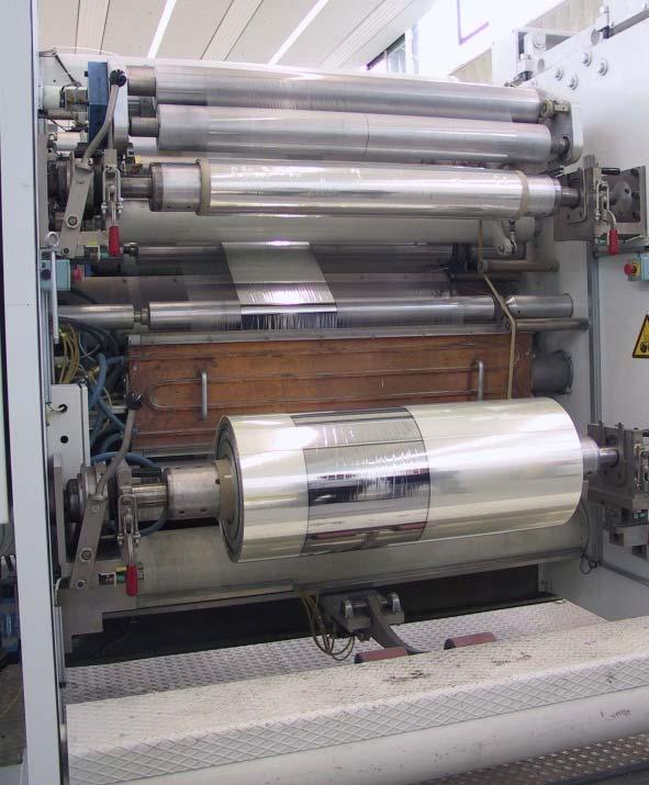

36 Methods of SE Data Collection (cont d) In-line
 Remove absorption at low wavelengths due")
37 Methods of SE Data Collection (cont d) Vacuum Ultraviolet (VUV) Spectral Range of nm (NIR option to nm) Remove absorption at low wavelengths due to O

")

38 Methods of SE Data Collection (cont d) Reflectometry/Transmission Temperature controlled

")


39 Methods of SE Data Collection (cont d) Liquid Cell Electrochemical Cell Sealed Cell
")

40 Methods of SE Data Collection (cont d) Textured Samples SEM picture of textured c-si
41 Ellipsometry Advantages Non-destructive, non-invasive, and non-contact Precise and reproducible Very sensitive to ultra-thin films < nm Applicable to almost any thin film materials (polymers, semiconductors, dielectrics, metals, alloys, etc.) Ideal for in-situ applications
42 P: Polarizer A: Analyzer C: Compensator S: Sample M: Modulator LC: Liquid Crystal Instrumentation Rotating Analyzer P S Rotating Compensator A Light Source P C Phase Modulation P S S M A A Detector Liquid Crystal Phase Modulation P LC S LC A
 Optical Fiber Shutter")
43 Phase Modulated Ellipsometer Fixed Analyzer Photoelastic Modulator (5KHz) Fixed Polarizer HORIBA UVISEL Detector Monochromator Sample Data Acquisition and Computer (DeltaPsi) Optical Fiber Shutter Xe lamp
 d E y d e i E y Signal detected at 5 khz!")
44 Photoelastic Modulator Principle An electrically driven retarder introducing a phase shift varying sinusoidally with time Linearly polarized light E x n E x modulator n Piezo electric transducer (5 khz) d E y d e i E y Signal detected at 5 khz!!! Elliptically polarized light Strained SiO bar; birefringence Modulation at 5 khz!
45 Fixed elements PME Advantages Excellent precision on Very fast acquisition rate (~ ms/point) Covers a wide spectral range from 9- nm High polarization modulation rate of 5 khz Ψ and are measured over their full range; Ψ [, 9 ] and [, 36 ]
46 SE Data Analysis Use Regression Analysis Measurement Model Fit Results Psi ( ) EXPERIMENTAL DATA.5 3 E (ev) Delta ( ) Layer Layer Substrate Psi ( ) EXPERIMENTAL DATA.5 3 E (ev) Delta ( ) Thickness Optical Constants Roughness (n,k) = f(lambda) for the TiO layer Re(Index) lambda (nm) Im(Index)
47 Goodness of fit: Data Fitting (X - ) X = Th Exp N - P - N N: Total number of measurables P: Total number of fit parameters In phase modulated ellipsometry X represents the couple (Is, Ic)
48 7 HORIBA, Ltd. All rights reserved. HORIBA, Ltd. All rights reserved. Kramers-Kronig (KK) Transformation d P d P Real and imaginary terms of optical properties are not independent! nk k n
49 Implications of KK Relationship Refractive index (n): Always follows slope of k Always increasing for absorbing materials, except in regions of anomalous dispersion n.85.35k Wavelength (nm)
50 Normal Dispersion: Dielectric Refractive index (n) decreases with increasing λ 4 n 3 AlGaAs SiN x SiO Wavelength (nm)
51 Anomalous Dispersion: Absorbing Region Refractive index (n) increases with increasing λ except where absorption peak occurs n k Wavelength (nm)
52 Quality of Results Goal: find simplest, realistic model Minimize Are results physical? Negative k? K-K consistent? Follow anomalous or normal dispersion? Other indicators Error bars (9% confidence limits) Correlation matrix


53 Applications-Thin Films At home: entertainment, comfort, security, appliances, energy savings Our health: medical imaging, portable diagnostics, DNA analysis, implantable devices At work: printers, PCs, In the car: engine control and powertrain, car body and safety, navigation... On the go: mobile phones, PDAs, MP3 players, tablets Our planet: energy-saving solutions, solar power, greener cars

: SnO, ZnO, ITO.")
54 Thin Films in Photovoltaics Structure Si: crystalline, nano, micro, poly, amorphous, textured... Compound semiconductor: III-V, SiGe, CdTe, CIS, CIGS... Organics: PCBM, P3HT, PEDOT:PSS... Transparent conducting oxides (TCO): SnO, ZnO, ITO... AR coating: SiN x, TiO x Metal contacts: Al, Ca, Mg Emitter Absorber


 coating")
55 Thin Films in Displays Devices: TFT-LCD LED, OLED Materials: a-si, Poly-Si, SiN, SiO, MgO,ITO,SnO,ZnO Liquid crystals, Antireflection (AR) coating Polarizing filters


56 Thin Films in Optoelectronics Devices: High sensitivity NIR & IR detectors Laser Diodes (LED) High speed electronics Materials: III-V compounds II-VI compounds Ternary alloys Quternary alloys Multiquantum well GaN, SiO,TiO.. Vision and microspot capabilities can be crucial

 New materials : Graphene,")
57 Thin Films in Microelectronics Materials: a-si, Poly-Si, SiN, SiO, High, Low materials Materials for 9 nm lithography ( DUV ) New materials : Graphene, Nanomaterials


58 Thin Films in Optical Coatings Applications: Antireflection coating Filtering coatings Antiscratch coating Decorative coatings Electrochromic coatings Materials: SiO x, High/Low refractive multilyers SiN,TiOx, WOx,


59 Thin films in Biochemistry Objective: Selective capture of protein Biosensors Materials: Substrate: Gold Layers: DNA, proteins


60 Thin Films in Metallurgy Objective: Hardness Antifriction coatings Decorative coating Anticorrosion coating Materials: SiO x, TiO, Al, Al O 3,CrO, DLC TiN,

61 Emerging Applications & Materials Objective: Microelectronics, Display & solar cells on flexible substrate Materials : Substrate: PET Layers: Polymers, a-si Low Cost Production Low Power Consumption
62 Summary Optical technique for studying thin film thickness and optical properties Ellipsometry vs. Reflectometry Jones/Stoke vectors and Jones/Mueller matrices used for light propagation Model based approach Many data collection methods Wide field of applications


63 Thank you! Check our website for future webinars on spectroscopic ellipsometry! HORIBA, Ltd. All rights reserved.

64 Questions? For additional information or questions about ellipsometry, please visit: Or
Discover the Difference
 M-2000 Discover the Difference Focused M-2000 The M-2000 line of spectroscopic ellipsometers is engineered to meet the diverse demands of thin film characterization. An advanced optical design, wide spectral
Spectroscopic Ellipsometry (SE) in Photovoltaic Applications
 in Photovoltaic Applications") Spectroscopic Ellipsometry (SE) in Photovoltaic Applications Jianing Sun, James Hilfiker, Greg Pribil, and John Woollam c-si PVMC Metrology Workshop July 2012, San Francisco PV key issues Material selection
Spectroscopic Ellipsometry (SE) in Photovoltaic Applications Jianing Sun, James Hilfiker, Greg Pribil, and John Woollam c-si PVMC Metrology Workshop July 2012, San Francisco PV key issues Material selection
1.1 FEATURES OF SPECTROSCOPIC ELLIPSOMETRY
 1 Introduction to Spectroscopic Ellipsometry Because of recent advances in computer technology, the spectroscopic ellipsometry technique has developed rapidly. As a result, the application area of spectroscopic
Brewster Angle and Total Internal Reflection
 Lecture 4: Polarization Outline 1 Polarized Light in the Universe 2 Brewster Angle and Total Internal Reflection 3 Descriptions of Polarized Light 4 Polarizers 5 Retarders Christoph U. Keller, Utrecht
VASE. J.A. Woollam Co., Inc. Ellipsometry Solutions
 VASE J.A. Woollam Co., Inc. Ellipsometry Solutions Accurate Capabilities The VASE is our most accurate and versatile ellipsometer for research on all types of materials: semiconductors, dielectrics, polymers,
Chiroptical Spectroscopy
 Chiroptical Spectroscopy Theory and Applications in Organic Chemistry Lecture 2: Polarized light Masters Level Class (181 041) Mondays, 8.15-9.45 am, NC 02/99 Wednesdays, 10.15-11.45 am, NC 02/99 28 Electromagnetic
Brewster Angle and Total Internal Reflection
 Lecture 5: Polarization Outline 1 Polarized Light in the Universe 2 Brewster Angle and Total Internal Reflection 3 Descriptions of Polarized Light 4 Polarizers 5 Retarders Christoph U. Keller, Leiden University,
Ellipsometry Tutorial
 Introduction Ellipsometry Tutorial [http://www.jawoollam.com/tutorial_1.html] This tutorial provided by the J. A. Woollam Co. is an introduction to ellipsometry for anyone interested in learning more about
DUV ( nm ) Characterization of Materials: A new instrument, the Purged UV Spectroscopic Ellipsometer,
 Characterization of Materials: A new instrument, the Purged UV Spectroscopic Ellipsometer,") WISE 2000, International Workshop on Spectroscopic Ellipsometry, 8 9 May 2000 DUV (150 350nm ) Characterization of Materials: A new instrument, the Purged UV Spectroscopic Ellipsometer, Pierre BOHER,,
WISE 2000, International Workshop on Spectroscopic Ellipsometry, 8 9 May 2000 DUV (150 350nm ) Characterization of Materials: A new instrument, the Purged UV Spectroscopic Ellipsometer, Pierre BOHER,,
Lecture 5: Polarization. Polarized Light in the Universe. Descriptions of Polarized Light. Polarizers. Retarders. Outline
 Lecture 5: Polarization Outline 1 Polarized Light in the Universe 2 Descriptions of Polarized Light 3 Polarizers 4 Retarders Christoph U. Keller, Leiden University, keller@strw.leidenuniv.nl ATI 2016,
Summary of presentation
 Slides 2-5 6-12 13 14-15 16-19 20 21-37 21-29 30-31 32-33 34-35 36-37 38-46 Summary of presentation Background to ellipsometry Fundamentals, and tutorial references Available ellipsometers Ellipsometry
16. More About Polarization
 16. More About Polarization Polarization control Wave plates Circular polarizers Reflection & polarization Scattering & polarization Birefringent materials have more than one refractive index A special
3B: Review. Nina Hong. U Penn, February J.A. Woollam Co., Inc. 1
 2014 J.A. Woollam Co., Inc. www.jawoollam.com 1 3B: Review Nina Hong U Penn, February 2014 2014 J.A. Woollam Co., Inc. www.jawoollam.com 2 Review 1A: Introduction to WVASE: Fun Quiz! 1B: Cauchy 2A: Pt-by-Pt
PMARIZED LI6HT FUNDAMENTALS AND APPLICATIONS EBWABD COLLETT. Measurement Concepts, Inc. Colts Neck, New Jersey
 PMARIZED LI6HT FUNDAMENTALS AND APPLICATIONS EBWABD COLLETT Measurement Concepts, Inc. Colts Neck, New Jersey Marcel Dekker, Inc. New York Basel Hong Kong About the Series Preface A Historical Note iii
OPTICAL ANALYSIS OF ZnO THIN FILMS USING SPECTROSCOPIC ELLIPSOMETRY AND REFLECTOMETRY.
 OPTICAL ANALYSIS OF ZnO THIN FILMS USING SPECTROSCOPIC ELLIPSOMETRY AND REFLECTOMETRY Katarína Bombarová 1, Juraj Chlpík 1,2, Soňa Flickyngerová 3, Ivan Novotný 3, Július Cirák 1 1 Institute of Nuclear
POLARIZATION OF LIGHT
 POLARIZATION OF LIGHT OVERALL GOALS The Polarization of Light lab strongly emphasizes connecting mathematical formalism with measurable results. It is not your job to understand every aspect of the theory,
Spectroscopic Ellipsometry Analysis of Opaque Gold Film for Epner Technology
 Customer Summary The optical constants n &k of an opaque gold film from Epner Technology were measured using J.A. Woollam VASE and IR-VASE spectroscopic ellipsometers over the wavelength range of.1 to
Lecture 2: Thin Films. Thin Films. Calculating Thin Film Stack Properties. Jones Matrices for Thin Film Stacks. Mueller Matrices for Thin Film Stacks
 Lecture 2: Thin Films Outline Thin Films 2 Calculating Thin Film Stack Properties 3 Jones Matrices for Thin Film Stacks 4 Mueller Matrices for Thin Film Stacks 5 Mueller Matrix for Dielectrica 6 Mueller
Polarized Light. Second Edition, Revised and Expanded. Dennis Goldstein Air Force Research Laboratory Eglin Air Force Base, Florida, U.S.A.
 Polarized Light Second Edition, Revised and Expanded Dennis Goldstein Air Force Research Laboratory Eglin Air Force Base, Florida, U.S.A. ш DEK KER MARCEL DEKKER, INC. NEW YORK BASEL Contents Preface to
OPTICAL Optical properties of multilayer systems by computer modeling
 Workshop on "Physics for Renewable Energy" October 17-29, 2005 301/1679-15 "Optical Properties of Multilayer Systems by Computer Modeling" E. Centurioni CNR/IMM AREA Science Park - Bologna Italy OPTICAL
Typical anisotropies introduced by geometry (not everything is spherically symmetric) temperature gradients magnetic fields electrical fields
 temperature gradients magnetic fields electrical fields") Lecture 6: Polarimetry 1 Outline 1 Polarized Light in the Universe 2 Fundamentals of Polarized Light 3 Descriptions of Polarized Light Polarized Light in the Universe Polarization indicates anisotropy
Lecture 6: Polarimetry 1 Outline 1 Polarized Light in the Universe 2 Fundamentals of Polarized Light 3 Descriptions of Polarized Light Polarized Light in the Universe Polarization indicates anisotropy
3.4 Elliptical Parameters of the Polarization Ellipse References
 Contents Preface to the Second Edition Preface to the First Edition A Historical Note Edward Collett iii v xiii PART 1: THE CLASSICAL OPTICAL FIELD Chapter 1 Chapter 2 Chapter 3 Chapter 4 Introduction
Calculating Thin Film Stack Properties. Polarization Properties of Thin Films
 Lecture 6: Thin Films Outline 1 Thin Films 2 Calculating Thin Film Stack Properties 3 Polarization Properties of Thin Films 4 Anti-Reflection Coatings 5 Interference Filters Christoph U. Keller, Utrecht
Polarimetry in the E-ELT era. Polarized Light in the Universe. Descriptions of Polarized Light. Polarizers. Retarders. Fundamentals of Polarized Light
 Polarimetry in the E-ELT era Fundamentals of Polarized Light 1 Polarized Light in the Universe 2 Descriptions of Polarized Light 3 Polarizers 4 Retarders Christoph U. Keller, Leiden University, keller@strw.leidenuniv.nl
ELLIPSOMETRY AND POLARIZED LIGHT
 ELLIPSOMETRY AND POLARIZED LIGHT R.M.A.AZZAM Department of Electrical Engineering University of New Orleans Lakefront, New Orleans, Louisiana, USA and N.M. В ASH AR A Electrical Materials Laboratory, Engineering
Supporting Information
 Supporting Information Devlin et al. 10.1073/pnas.1611740113 Optical Characterization We deposit blanket TiO films via ALD onto silicon substrates to prepare samples for spectroscopic ellipsometry (SE)
Learn how reflection at interfaces with different indices of refraction works and how interfaces can change the polarization states of light.
 Slide 1 Goals of the Lab: Learn how reflection at interfaces with different indices of refraction works and how interfaces can change the polarization states of light. Learn how to measure the influence
2. Transparent Films. Neha Singh October 2010
 2. Transparent Films Neha Singh October 2010 Course Overview Day 1: Introduction and Theory Transparent Films Microstructure EMA Surface roughness Ultra thin films Uniqueness test UV Absorption Point-by-point
Lecture 20 Optical Characterization 2
 Lecture 20 Optical Characterization 2 Schroder: Chapters 2, 7, 10 1/68 Announcements Homework 5/6: Is online now. Due Wednesday May 30th at 10:00am. I will return it the following Wednesday (6 th June).
Measurement of Optical Constants (n,k) using MProbe
 using MProbe") Thin Film Measurement solution Software, sensors, custom development and integration Measurement of Optical Constants (n,k) using MProbe Measurement of spectroscopic reflectance allows determining both
Thin Film Measurement solution Software, sensors, custom development and integration Measurement of Optical Constants (n,k) using MProbe Measurement of spectroscopic reflectance allows determining both
Film Thickness Measurement System - Principle and Applications -
 Film Thickness Measurement System - Principle and Applications - 1 - CONTENTS - 1. Thin Films for Application 2. Film Thickness Measurement Requirements 3. Film Thickness Measurement Methods 4. Comparison
Lecture 4: Polarisation of light, introduction
 Lecture 4: Polarisation of light, introduction Lecture aims to explain: 1. Light as a transverse electro-magnetic wave 2. Importance of polarisation of light 3. Linearly polarised light 4. Natural light
INA I N. Practical training ellipsometry. Lab training nanosensorics Supervisor: Uh-Myong Ha. University of Kassel. Version: December 22, 2014
 INA I N nstitut für anostrukturtechnologie und Analytik Practical training ellipsometry Lab training nanosensorics Supervisor: Uh-Myong Ha Version: December 22, 2014 University of Kassel Contents 1 Introduction
Introduction to Polarization
 Phone: Ext 659, E-mail: hcchui@mail.ncku.edu.tw Fall/007 Introduction to Polarization Text Book: A Yariv and P Yeh, Photonics, Oxford (007) 1.6 Polarization States and Representations (Stokes Parameters
Chap. 2. Polarization of Optical Waves
 Chap. 2. Polarization of Optical Waves 2.1 Polarization States - Direction of the Electric Field Vector : r E = E xˆ + E yˆ E x x y ( ω t kz + ϕ ), E = E ( ωt kz + ϕ ) = E cos 0 x cos x y 0 y - Role :
Waves & Oscillations
 Physics 42200 Waves & Oscillations Lecture 32 Electromagnetic Waves Spring 2016 Semester Matthew Jones Electromagnetism Geometric optics overlooks the wave nature of light. Light inconsistent with longitudinal
Lecture 8: Polarimetry 2. Polarizers and Retarders. Polarimeters. Scattering Polarization. Zeeman Effect. Outline
 Lecture 8: Polarimetry 2 Outline 1 Polarizers and Retarders 2 Polarimeters 3 Scattering Polarization 4 Zeeman Effect Christoph U. Keller, Utrecht University, C.U.Keller@uu.nl Observational Astrophysics
NON-DESTRUCTIVE EVALUATION IN MANUFACTURING USING SPECTROSCOPIC. John A. Woollam and Paul G. Snyder
 NON-DESTRUCTIVE EVALUATION IN MANUFACTURING USING SPECTROSCOPIC ELLIPSOMETRY John A. Woollam and Paul G. Snyder Center for Microelectronic and Optical Materials Research, and Department of Electrical Engineering
Ellipsometry measures variations of the polarization state of light reflected from a
 Ellipsometry (by Klaus-Jochen Eichhorn and Boris Mahltig) Ellipsometry measures variations of the polarization state of light reflected from a surface /1/ (FIG.1). The experimental data are expressed as
OPSE FINAL EXAM Fall 2016 YOU MUST SHOW YOUR WORK. ANSWERS THAT ARE NOT JUSTIFIED WILL BE GIVEN ZERO CREDIT.
 CLOSED BOOK. Equation Sheet is provided. YOU MUST SHOW YOUR WORK. ANSWERS THAT ARE NOT JUSTIFIED WILL BE GIVEN ZERO CREDIT. ALL NUMERICAL ANSERS MUST HAVE UNITS INDICATED. (Except dimensionless units like
Optics of Liquid Crystal Displays
 Optics of Liquid Crystal Displays Second Edition POCHIYEH CLAIRE GU WILEY A John Wiley & Sons, Inc., Publication Contents Preface Preface to the First Edition xiii xv Chapter 1. Preliminaries 1 1.1. Basic
Coherent Superposition of Mueller-Jones States: Synthesizing Mueller Matrices with an Ellipsometer
 Coherent Superposition of Mueller-Jones States: Synthesizing Mueller Matrices with an Ellipsometer Ertan Kuntman, Mehmet A. Kuntman Oriol Arteaga SPECTROSCOPIC ELLIPSOMETRY FOCUS TOPIC Young s double slit
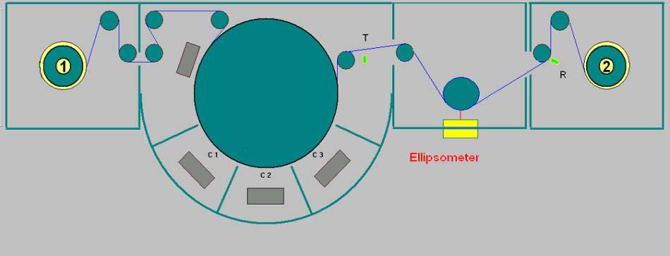
Real-time and in-line Optical monitoring of Functional Nano-Layer Deposition on Flexible Polymeric Substrates
 Real-time and in-line Optical monitoring of Functional Nano-Layer Deposition on Flexible Polymeric Substrates S. Logothetidis Lab for Thin Films, Nanosystems & Nanometrology, Aristotle University of Thessaloniki,
Polarization Mode Dispersion
 Unit-7: Polarization Mode Dispersion https://sites.google.com/a/faculty.muet.edu.pk/abdullatif Department of Telecommunication, MUET UET Jamshoro 1 Goos Hänchen Shift The Goos-Hänchen effect is a phenomenon
Lab #13: Polarization
 Lab #13: Polarization Introduction In this experiment we will investigate various properties associated with polarized light. We will study both its generation and application. Real world applications
Lecture 4: Anisotropic Media. Dichroism. Optical Activity. Faraday Effect in Transparent Media. Stress Birefringence. Form Birefringence
 Lecture 4: Anisotropic Media Outline Dichroism Optical Activity 3 Faraday Effect in Transparent Media 4 Stress Birefringence 5 Form Birefringence 6 Electro-Optics Dichroism some materials exhibit different
PHOTOVOLTAICS Fundamentals
 PHOTOVOLTAICS Fundamentals PV FUNDAMENTALS Semiconductor basics pn junction Solar cell operation Design of silicon solar cell SEMICONDUCTOR BASICS Allowed energy bands Valence and conduction band Fermi
Fresnel Equations cont.
 Lecture 11 Chapter 4 Fresnel quations cont. Total internal reflection and evanescent waves Optical properties of metals Familiar aspects of the interaction of light and matter Fresnel quations: phases
Summary of Beam Optics
 Summary of Beam Optics Gaussian beams, waves with limited spatial extension perpendicular to propagation direction, Gaussian beam is solution of paraxial Helmholtz equation, Gaussian beam has parabolic
Session 3B Using the Gen-Osc Layer to Fit Data
 Session 3B Using the Gen-Osc Layer to Fit Data Andrew Martin UPenn, February 2014 2014 J.A. Woollam Co., Inc. www.jawoollam.com 1 Using Gen-Osc to Fit Data Pre-built Existing Genosc Layer Library optical
Electromagnetic Waves Across Interfaces
 Lecture 1: Foundations of Optics Outline 1 Electromagnetic Waves 2 Material Properties 3 Electromagnetic Waves Across Interfaces 4 Fresnel Equations 5 Brewster Angle 6 Total Internal Reflection Christoph
Physics of Organic Semiconductor Devices: Materials, Fundamentals, Technologies and Applications
 Physics of Organic Semiconductor Devices: Materials, Fundamentals, Technologies and Applications Dr. Alex Zakhidov Assistant Professor, Physics Department Core faculty at Materials Science, Engineering
Experiment 5 Polarization and Modulation of Light
 1. Objective Experiment 5 Polarization and Modulation of Light Understanding the definition of polarized and un-polarized light. Understanding polarizer and analzer definition, Maluse s law. Retarding
Optics. n n. sin c. sin
 Optics Geometrical optics (model) Light-ray: extremely thin parallel light beam Using this model, the explanation of several optical phenomena can be given as the solution of simple geometric problems.
Chap. 5. Jones Calculus and Its Application to Birefringent Optical Systems
 Chap. 5. Jones Calculus and Its Application to Birefringent Optical Systems - The overall optical transmission through many optical components such as polarizers, EO modulators, filters, retardation plates.
Calculating Thin Film Stack Properties
 Lecture 5: Thin Films Outline 1 Thin Films 2 Calculating Thin Film Stack Properties 3 Fabry-Perot Tunable Filter 4 Anti-Reflection Coatings 5 Interference Filters Christoph U. Keller, Leiden University,
Supplementary Figure 1 Comparison between normalized and unnormalized reflectivity of
 Supplementary Figures Supplementary Figure 1 Comparison between normalized and unnormalized reflectivity of bulk SrTiO 3. The normalized high-energy reflectivity (0.5 35 ev) of SrTiO 3 is compared to the
: Imaging Systems Laboratory II. Laboratory 6: The Polarization of Light April 16 & 18, 2002
 151-232: Imaging Systems Laboratory II Laboratory 6: The Polarization of Light April 16 & 18, 22 Abstract. In this lab, we will investigate linear and circular polarization of light. Linearly polarized
Optics and Optical Design. Chapter 6: Polarization Optics. Lectures 11-13
 Optics and Optical Design Chapter 6: Polarization Optics Lectures 11-13 Cord Arnold / Anne L Huillier Polarization of Light Arbitrary wave vs. paraxial wave One component in x-direction y x z Components
Near-Infrared to Vacuum Ultraviolet (VUV) Dielectric Properties of LaAlO 3
 Dielectric Properties of LaAlO 3") Near-Infrared to Vacuum Ultraviolet (VUV) Dielectric Properties of LaAlO 3 Jacqueline Cooke 1, Tom Tiwald, Nuwanjula Samarasingha 1, Nalin Fernando 1, Stefan Zollner 1 1. Department of Physics, New Mexico
Near-Infrared to Vacuum Ultraviolet (VUV) Dielectric Properties of LaAlO 3 Jacqueline Cooke 1, Tom Tiwald, Nuwanjula Samarasingha 1, Nalin Fernando 1, Stefan Zollner 1 1. Department of Physics, New Mexico
50%-50% Beam Splitters Using Transparent Substrates Coated by Single- or Double-Layer Quarter-Wave Thin Films
 University of New Orleans ScholarWorks@UNO University of New Orleans Theses and Dissertations Dissertations and Theses 5-22-2006 50%-50% Beam Splitters Using Transparent Substrates Coated by Single- or
4. Circular Dichroism - Spectroscopy
 4. Circular Dichroism - Spectroscopy The optical rotatory dispersion (ORD) and the circular dichroism (CD) are special variations of absorption spectroscopy in the UV and VIS region of the spectrum. The
Multilayer Thin Films Dielectric Double Chirped Mirrors Design
 International Journal of Physics and Applications. ISSN 974-313 Volume 5, Number 1 (13), pp. 19-3 International Research Publication House http://www.irphouse.com Multilayer Thin Films Dielectric Double
Optics and Optical Design. Chapter 6: Polarization Optics. Lectures 11 13
 Optics and Optical Design Chapter 6: Polarization Optics Lectures 11 13 Cord Arnold / Anne L Huillier Polarization of Light Arbitrary wave vs. paraxial wave One component in x direction y x z Components
PHYSICS nd TERM Outline Notes (continued)
") PHYSICS 2800 2 nd TERM Outline Notes (continued) Section 6. Optical Properties (see also textbook, chapter 15) This section will be concerned with how electromagnetic radiation (visible light, in particular)
PHYSICS 2800 2 nd TERM Outline Notes (continued) Section 6. Optical Properties (see also textbook, chapter 15) This section will be concerned with how electromagnetic radiation (visible light, in particular)
Physics I Keystone Institute Technology & Management Unit-II
 Un-polarized light Ordinary light is a collection of wave trains emitted by atoms or group of atoms with coherent time no longer than 10-8 second. Each wave train has different orientation and phase of
Superconductivity Induced Transparency
 Superconductivity Induced Transparency Coskun Kocabas In this paper I will discuss the effect of the superconducting phase transition on the optical properties of the superconductors. Firstly I will give
Wave Propagation in Uniaxial Media. Reflection and Transmission at Interfaces
 Lecture 5: Crystal Optics Outline 1 Homogeneous, Anisotropic Media 2 Crystals 3 Plane Waves in Anisotropic Media 4 Wave Propagation in Uniaxial Media 5 Reflection and Transmission at Interfaces Christoph
Chapter 7. Solar Cell
 Chapter 7 Solar Cell 7.0 Introduction Solar cells are useful for both space and terrestrial application. Solar cells furnish the long duration power supply for satellites. It converts sunlight directly
Lecture 11: Polarized Light. Fundamentals of Polarized Light. Descriptions of Polarized Light. Scattering Polarization. Zeeman Effect.
 Lecture 11: Polarized Light Outline 1 Fundamentals of Polarized Light 2 Descriptions of Polarized Light 3 Scattering Polarization 4 Zeeman Effect 5 Hanle Effect Fundamentals of Polarized Light Electromagnetic
Light Waves and Polarization
 Light Waves and Polarization Xavier Fernando Ryerson Communications Lab http://www.ee.ryerson.ca/~fernando The Nature of Light There are three theories explain the nature of light: Quantum Theory Light
Polarization of Light and Birefringence of Materials
 Polarization of Light and Birefringence of Materials Ajit Balagopal (Team Members Karunanand Ogirala, Hui Shen) ECE 614- PHOTONIC INFORMATION PROCESSING LABORATORY Abstract-- In this project, we study
OPSE FINAL EXAM Fall 2015 YOU MUST SHOW YOUR WORK. ANSWERS THAT ARE NOT JUSTIFIED WILL BE GIVEN ZERO CREDIT.
 CLOSED BOOK. Equation Sheet is provided. YOU MUST SHOW YOUR WORK. ANSWERS THAT ARE NOT JUSTIFIED WILL BE GIVEN ZERO CREDIT. ALL NUMERICAL ANSERS MUST HAVE UNITS INDICATED. (Except dimensionless units like
Electromagnetism II Lecture 7
 Electromagnetism II Lecture 7 Instructor: Andrei Sirenko sirenko@njit.edu Spring 13 Thursdays 1 pm 4 pm Spring 13, NJIT 1 Previous Lecture: Conservation Laws Previous Lecture: EM waves Normal incidence
2A: Absorbing Materials Pt-by-Pt and GenOsc
 2014 J.A. Woollam Co., Inc. www.jawoollam.com 1 2A: Absorbing Materials Pt-by-Pt and GenOsc Nina Hong U Penn, February 2014 2014 J.A. Woollam Co., Inc. www.jawoollam.com 2 Pt-by-Pt Fit UV Absorbing Films
Jones vector & matrices
 Jones vector & matrices Department of Physics 1 Matrix treatment of polarization Consider a light ray with an instantaneous E-vector as shown y E k, t = xe x (k, t) + ye y k, t E y E x x E x = E 0x e i
14. Matrix treatment of polarization
 14. Matri treatment of polarization This lecture Polarized Light : linear, circular, elliptical Jones Vectors for Polarized Light Jones Matrices for Polarizers, Phase Retarders, Rotators (Linear) Polarization
Photovoltaic cell and module physics and technology
 Photovoltaic cell and module physics and technology Vitezslav Benda, Prof Czech Technical University in Prague benda@fel.cvut.cz www.fel.cvut.cz 6/21/2012 1 Outlines Photovoltaic Effect Photovoltaic cell
Nanophotonics: solar and thermal applications
 Nanophotonics: solar and thermal applications Shanhui Fan Ginzton Laboratory and Department of Electrical Engineering Stanford University http://www.stanford.edu/~shanhui Nanophotonic Structures Photonic
Optical Systems Program of Studies Version 1.0 April 2012
 Optical Systems Program of Studies Version 1.0 April 2012 Standard1 Essential Understand Optical experimental methodology, data analysis, interpretation, and presentation strategies Essential Understandings:
Polarization properties of corner-cube retroreflectors: Theory and experiment
 University of New Orleans ScholarWorks@UNO Electrical Engineering Faculty Publications Department of Electrical Engineering 3--997 Polarization properties of corner-cube retroreflectors: Theory and experiment
17. Jones Matrices & Mueller Matrices
 7. Jones Matrices & Mueller Matrices Jones Matrices Rotation of coordinates - the rotation matrix Stokes Parameters and unpolarized light Mueller Matrices R. Clark Jones (96-24) Sir George G. Stokes (89-93)
Homework 1. Nano Optics, Fall Semester 2017 Photonics Laboratory, ETH Zürich
 Homework 1 Contact: mfrimmer@ethz.ch Due date: Friday 13.10.2017; 10:00 a.m. Nano Optics, Fall Semester 2017 Photonics Laboratory, ETH Zürich www.photonics.ethz.ch The goal of this homework is to establish
Beatrice Beyer ISFOE 2014 Thessaloniki, Greece
 Beatrice Beyer ISFOE 2014 Thessaloniki, Greece What? Graphene which is both highly conductive and transparent Large volume production Process safety Proof of concept for use as transparent electrode Why?
FUNDAMENTALS OF POLARIZED LIGHT
 FUNDAMENTALS OF POLARIZED LIGHT A STATISTICAL OPTICS APPROACH Christian Brosseau University of Brest, France A WILEY-INTERSCIENCE PUBLICATION JOHN WILEY & SONS, INC. New York - Chichester. Weinheim. Brisbane
SHG Spectroscopy. Clean surfaces Oxidation SOI wafer
 SHG Spectroscopy Clean surfaces Oxidation SOI wafer Scan regions Idler: 730-1050 nm 1000-1400 nm Signal: 680-550 nm Ti:Sapphire: 700-1000 nm 600-500 nm SHG set-up Bergfeld, Daum, PRL 90, 2915 SHG from
Summary of Fourier Optics
 Summary of Fourier Optics Diffraction of the paraxial wave is described by Fresnel diffraction integral, u(x, y, z) = j λz dx 0 dy 0 u 0 (x 0, y 0 )e j(k/2z)[(x x 0) 2 +(y y 0 ) 2 )], Fraunhofer diffraction
Nanocomposite photonic crystal devices
 Nanocomposite photonic crystal devices Xiaoyong Hu, Cuicui Lu, Yulan Fu, Yu Zhu, Yingbo Zhang, Hong Yang, Qihuang Gong Department of Physics, Peking University, Beijing, P. R. China Contents Motivation
Homework 1. Nano Optics, Fall Semester 2018 Photonics Laboratory, ETH Zürich
 Homework 1 Contact: mfrimmer@ethz.ch Due date: Friday 12 October 2018; 10:00 a.m. Nano Optics, Fall Semester 2018 Photonics Laboratory, ETH Zürich www.photonics.ethz.ch The goal of this homework is to
Chapter 1 - The Nature of Light
 David J. Starling Penn State Hazleton PHYS 214 Electromagnetic radiation comes in many forms, differing only in wavelength, frequency or energy. Electromagnetic radiation comes in many forms, differing
Ellipsometry. Introduction. Measurement Principles
 Ellipsometry Introduction Ellipsometry is the measurement of the effect of reflection on the state of polarization of light. The result of an ellipsometric measurement can be the complex refractive index
Development of active inks for organic photovoltaics: state-of-the-art and perspectives
 Development of active inks for organic photovoltaics: state-of-the-art and perspectives Jörg Ackermann Centre Interdisciplinaire de Nanoscience de Marseille (CINAM) CNRS - UPR 3118, MARSEILLE - France
Overview in Images. 5 nm
 Overview in Images 5 nm K.S. Min et al. PhD Thesis K.V. Vahala et al, Phys. Rev. Lett, 85, p.74 (000) J. D. Joannopoulos, et al, Nature, vol.386, p.143-9 (1997) S. Lin et al, Nature, vol. 394, p. 51-3,
THIN-FILM MEASUREMENT
 ADVANCED THIN-FILM MEASUREMENT SYSTEMS TAKING THE MYSTERY OUT OF THIN-FILM MEASUREMENT ABOUT THIN-FILM MEASUREMENTS THIN-FILM MEASUREMENT Introduction Thin film Thin films are very thin layers of material
Optics, Optoelectronics and Photonics
 Optics, Optoelectronics and Photonics Engineering Principles and Applications Alan Billings Emeritus Professor, University of Western Australia New York London Toronto Sydney Tokyo Singapore v Contents
PHYS 4400, Principles and Varieties of Solar Energy Instructor: Randy J. Ellingson The University of Toledo
 Light and Photons PHYS 4400, Principles and Varieties of Solar Energy Instructor: Randy J. Ellingson The University of Toledo January 16, 2014 Light What is light? Electromagnetic wave direction of the
Spectroscopic mapping polarimetry in Bragg Micro-cavities
 Spectroscopic mapping polarimetry in Bragg Micro-cavities Author: David Ramos Santesmases Advisor: Oriol Arteaga Facultat de Física, Universitat de Barcelona, Diagonal 645, 08028 Barcelona, Spain*. Abstract:
AP 5301/8301 Instrumental Methods of Analysis and Laboratory
 1 AP 5301/8301 Instrumental Methods of Analysis and Laboratory Lecture 7 Optical spectroscopies Prof YU Kin Man E-mail: kinmanyu@cityu.edu.hk Tel: 3442-7813 Office: P6422 Lecture 7: outline 2 Introduction
Analysis of optical spectra by computer simulation - from basics to batch mode
 M.Theiss Hard- and Software for Optical Spectroscopy Dr.-Bernhard-Klein-Str. 110, D-52078 Aachen Phone: (49) 241 5661390 Fax: (49) 241 9529100 E-mail: theiss@mtheiss.com Web: www.mtheiss.com Analysis of
The design of an integrated XPS/Raman spectroscopy instrument for co-incident analysis
 The design of an integrated XPS/Raman spectroscopy instrument for co-incident analysis Tim Nunney The world leader in serving science 2 XPS Surface Analysis XPS +... UV Photoelectron Spectroscopy UPS He(I)