A Multi-Gait Soft Robot. Supporting Information
|
|
|
- Brian Stephens
- 6 years ago
- Views:
Transcription
1 A Multi-Gait Soft Robot Supporting Information Robert F. Shepherd, Filip Ilievski, Wonjae Choi, Stephen A. Morin, Adam A. Stokes, Aaron D. Mazzeo, Xin Chen, Michael Wang and George M. Whitesides, * Department of Chemistry and Chemical Biology, Harvard University, Oxford Street, Cambridge, Massachusetts 038 Wyss Institute for Biologically Inspired Engineering 60 Oxford Street, Cambridge, Massachusetts 038 * Corresponding author, gwhitesides@gmwgroup.harvard.edu
2 SI. Materials and Methods Soft Robot Fabrication. Masters for the pneu-nets were fabricated in ABS (acrylonitrile butadiene styrene) using a 3D printer (Dimension 3D; Stratasys, Inc.) We molded pneunets into a highly extensible, elastomeric material (Ecoflex ; Smooth-On, Inc.) and then layered them onto a relatively inextensible, compliant sheet (PDMS; Sylgard 84, Dow-Corning) (Fig. ). We then inserted five soft, flexible tubes (mm I.D., silicone rubber) into a hub located at the posterior section of the soft robot; this hub fed the five separate pneu-nets (the tubing was held in place by compression from the surrounding, punctured Ecoflex silicone rubber). We also fabricated a robot capable of faster crawling locomotion using an extensible elastomer (Ecoflex ; Smooth-On, Inc.) with a larger Young s Modulus than Ecoflex The physical dimensions of the robot, as well as the dimensions of the pneu-nets are shown in Fig. S. Both the Ecoflex elastomers, as well as the Sylgard 84 were cured at 75 o C for 60 minutes prior to use. We glued the cured Ecoflex layer to the cured Sylgard 84 layer by using a thin, uncured layer of Sylgard 84 as glue; we then allowed the uncured PDMS to permeate into the Ecoflex and Sylgard 84 layers for 60 minutes and finished the bonding of the glue layer by baking the robot in an oven at 75 o C for 60 minutes. To increase production throughput, we typically fabricated four robots in parallel. Manual Control for Obstacle Navigation. We connected the four legs of the robot to Manifold One (M; manifold here means a group of pressure regulators such as buttons and toggle switches) at pressure, P, and the spine was connected to either M for undulation or Manifold Two (M) at a lower pressure, P (4 psi), for crawling. M has
3 button valves, which allowed the pneu-nets to be pressurized when depressed, and vented to atmospheric when released (Fig. S). M had a switch valve that kept the pneu-nets pressurized until the valve was switched off. Kinematic Analysis. We determined the speed of actuation of a leg (PN 5) of the tetrapod for different input pressures (Figure S3). We captured video at 00 frames per second (fps) using a high speed video camera (Phantom V7.; Vision Research) and calculated the time it took for the leg to reach a curvature of cm for pressures varying from 4.5 psi to 0.0 psi. We also tracked the motion of the robot during an undulation and crawling sequence. We used Matlab 009a s (The Mathworks, Inc.) Image Toolbox to determine the center of mass of the robot (centroid) for each frame of the videos shown in Video S and Video S. We plotted the X- and Y-position of the centroid vs. time for undulation and crawling gaits (Figure S4). For the crawling gait, we inflated the robot s spine after eight seconds and initiated crawling at thirteen seconds. For both gaits, after ~35 seconds, the tether begins to affect the weighting of the centroid and reduces the positional accuracy of our image analysis. SI. Calculations of the Bending Stiffness of an Elastomer Membrane with Embedded Pneumatic Channels. Curvature () of a Pressurized Membrane. Figure S5A shows a schematic drawing of an elastomer membrane incorporating embedded pneumatic channels (represented by circles). The bottom layer of the membrane structure is assumed to be unstretchable, but to possess negligible thickness so that the layer does not have significant bending modulus. Pneumatic channels are assumed to be circular for the sake of analytical simplicity. Each of the pneumatic channels is assumed to have infinite length (along the z
4 axis in the figure). In Fig. S5A, the pneumatic channels are not pressurized (atmospheric pressure P atm inside the channels) and the membrane is at its resting, flat state (the radius of an undeformed channel is R atm, and length of the membrane = R atm N; N is the number of channels). Fig. S5B shows the shape of the membrane when the pneumatic channels are pressurized (P > P atm ). The channels expand (R atm R ) to adopt the new pressure, leading to a mismatch between the lengths of the membrane along the center of pneumatic channels (R N) and along the unstretched bottom layer (R atm N). Eq. S describes the kinematic correlation between radius of curvature of the membrane (R m = /; see Fig. S5C for parameters) and the expansion of the pneumatic cells (R atm R ): R Rm R m R R atm (S) Eqs. S S5 relate the expansion of pneumatic cells (R atm R ) and the applied pressure (P, P atm ; Pa or kg m - s - ), based on the free-body diagram shown in Figure S5D: to balance the pressure difference across the walls of pneumatic cells, the tensional force (T; per unit length along z axis; kg s - ) along the wall should be (): atm T R ( P P ) (S) The constitutive equation Eq. S3 describes the wall-tension T as a function of the strain of the material:() T E t (S3) 3
5 In Equation S3, E (kg m - s - ), t (m) and are the elastic modulus, thickness and strain ( R R atm ) / R ( atm ) of the channel wall, respectively. Stress-strain relationship for elastomers is highly nonlinear both the elastic modulus of elastomer and the thickness of a channel wall changes as a pneumatic cell is stretched. We ignore these nonlinearities in this analysis as we are interested only in the order of magnitude relationship between the curvature of a membrane and the applied pressure. Combining Eqs. S and S3, one can eliminate the term T and obtain a direct relation between the applied pressure and the strain of pneumatic cells: Ratm( P Patm ) (S4) Et R ( P P ) atm atm The ratio between radii of the inflated and the original pneumatic cells ( R / R ) is then: atm R Et (S5) R Et R P P ) atm atm( atm Combining Eqs. S and S5 leads to an explicit equation that allows us to describe the curvature in terms of the expansion ratio, and eventually the applied pressure (P - P atm ): R atm (S6) Fig. S6 shows the curvature of the membrane of typical parameters (E ~ 40 kpa, R atm ~ mm, and t ~ mm) plotted to the difference of pressures ( P Patm). The solid line 4
6 represents the curvature multiplied by the initial radius of pneumatic cells (R m ) and is non-monotonic. This is because the strain () and consequently the curvature () of the membrane increases nonlinearly according to pressure (see Eq. S4). When the pressure is so large that the denominator in Eq. S4 becomes zero, the strain diverges to infinity, and the ratio between the radius of a pneumatic cell and the radius of curvature for the membrane approaches unity ( R ). In reality, the wall of a pneumatic cell would burst due to the high strain; thus, it should be noted that the approximation based on this analysis is valid only for a low strain regime. Bending Modulus of the Pressurized Membrane. The other effect of pressurizing pneumatic channels is the increase of the bending modulus (resistance against bending; kg m - s - ) of the membrane (). Such stiffening phenomenon is used to make pneumatic structures such as portable pools for kids and camouflage tanks made with balloons (3). This section aims to obtain a qualitative estimate of the bending modulus of a pressurized membrane. Figure S7 shows three membranes: A pressurized only, B pressurized and forced to bend further, and C pressurized and forced to flatten. The channels of the membranes in Figs. S7B and S7C become distorted from the original circular shapes into (we assume) ellipses to adopt the change of curvature that is induced by external torque (arrows in the figure). Figure S6D illustrates that such change of shapes will increase the area of the walls of pneumatic channels: assuming the air inside the pneumatic channels is incompressible, the volumes inside the circular and elliptic channels is constant (i.e., R ab, we assume the channel is infinitely long along the z axis in Fig. S7D). The 5
7 lengths of major and minor axes thus correlate with each other by b R / a. The circumference C of the ellipse for a given volume is then greater than that of the nondistorted circular pneumatic channel, (i.e., C > R ). This rest of section shows that, the more a pneumatic channel is inflated, the more elastic energy is required to cause the same amount of distortion from a circular to elliptic shape. Then it is straightforward that a pressurized membrane is more difficult to bend, because the bending of a membrane leads to the deformation of a channel (circle to ellipse) and thus the change of elastic energy. Step. Deriving the Elastic Energy Associated with the Deformation of a Pneumatic Channel. Deriving an exact, analytical solution for the circumference of an ellipse is impossible, hence we used the following estimation (4): C 3 a b (3a b)( a 3b) (S7) When the deformation is infinitesimal (i.e. a R, R ). b R / a can be approximated to be b R, and Eq. S7 can be re-written as: 6R 4R R C (S8) The circumference in S8 is always greater than that of the original circle (C > R ), and consequently, the deformation of a pneumatic channel leads to the corresponding increase of the elastic energy stored by the wall of the pneumatic channel. For the original, 6
8 circular shape of a pressurized pneumatic channel, the strain of the wall is given as ( R R atm ) / R atm. The elastic potential energy, PE, stored in the elastic wall, per channel of unit length along the z axis, is then calculated to be: PE EV R R atm ERt ERt R (S9) atm Here E (kg m - s - ) is elastic modulus of the elastomer, V (m 3 ) is the volume of the elastomer, is the strain (ratio between the final and the initial lengths). On the other hand, the potential energy PE stored in the elastic wall of the distorted, elliptic channel is (of course, per channel of unit length along the z axis): R Ratm 4 PE' EV ( ') E R t (S0) 4 R atm Dropping higher order terms from Eq. S0, we get Eq. S: PE' 4 PE E t (S) The volume conservation of the elastomer material requires the wall thickness (t) of an inflated pneumatic channel to be related to the initial thickness at the atmospheric pressure (t atm ) as the following: R t R t atm atm (S) Combining Eq. S and S leads to Eq. S3 that describes the change of elastic energy: 7
9 PE' R t atm atm PE E E tatm (S3) 4 R 4 Eq. S3 shows that, for a pneumatic channel with a given geometry and material property (E, t atm ), when the channel is pressurized and strained more ( becomes higher), the deformation of the pneumatic channel from a circular to an elliptic shape ( R R ) leads to a larger change of elastic energy. That is, the pneumatic channels become stiffer when they are pressurized. Step. Deformation of a Pneumatic Channel due to the Torque-Induced Bending of a Membrane. The next step is to obtain the relation between the bending deformation of the entire membrane and the distortion of a pneumatic channel. One can start from the original relationship between the radius of curvature of a membrane and that of a pneumatic cell (Eq. S), which is repeated below for convenience: R Rm R m R R atm (S) If one forces the membrane to increase or decrease its radius of curvature by a small amount, the lengths of an ellipse (a along the membrane, b perpendicular to membrane) and the radius of curvature of a distorted membrane ( R ' R relation: m m ) should hold a similar Rm ' R 'b m a R atm (S4) Converting Eq. S4 into a differential form, one can obtain: 8
10 R m R m R ( R ) Ratm (S5), and combining Eqs. S and S5 yields R R atm (S6) R m Here the term d represents the deformation of the original, circular channel (radius = R ) into an elliptical shape (axis lengths = R ). Combining Eq. S3 and Eq. S6, one can calculate the variation of the potential energy for one pneumatic channel, per given change of radius of membrane curvature : 4 Ratmtatm Ratm PE ' PE E Et 4 4 atm (S7) R Rm meaning the change of elastic energy (PE PE) due to the torque-induced bending of the membrane ( R m R m ) is highly dependent on the pre-strain () of the pneumatic channels that was caused by the pressure. In short, pressurized membranes become stiffer. SI5. References. Timoshenko SP (970) Theory of Elasticity (McGraw-Hill).. Tabata O, Konishi S, Cusin P, Ito Y, Kawai F, Hirai S, Kawamura S (00) Micro fabricated tunable bending stiffness devices. Sensors and Actuators A Chi JY and Paulettie RMO (005) An outline of the evolution of pneumatic structures. II Simposio Latinoamericano de Tensoestructuras Caracas, Venezuela, May , Pauletti.Pdf 9
11 4. Almkvist G, Berndt B Gauss (988) Landen, Ramanujan, the Arithmetic- Geometric Mean, Ellipses, Pi, and The Ladies Diary. American Mathematical Monthly, 95:
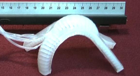
12 Figure Legends Fig. S. A Top view of the quadruped, with dimensions in millimeters. The length of the robot is 35.7 mm, the width 58.5 mm. B The side view of PN 3, showing the thickness of the Ecoflex layer (Layer ) to be 5.3 mm, the pneu-net channel thickness to be 0.5 mm, the channel connecting the pneu-nets to be.0 mm thick, and the Sylgard 84 (Layer ) strain limiting layer to be.0mm.
13
14 Fig. S. A Computer control. Schematic diagram of a system of solenoid-valves controlled via computer. The computer is programmed to actuate the soft robot in undulation or crawling gait at a pressure of 7 psi. B Manual control. Schematic diagram of a system of spring-valves controlled via manual operation (depressing the spring-valve actuates the corresponding pneu-net). The valve configuration for (top) undulation gait requires a valve for each pneu-net and uses a pressure of 7 psi. The (bottom) crawl gait uses an individual valve for PN -, -, -4, and -5. PN 3 is held at a constant pressure of 4 psi. The direction of the pressurized air-flow is indicated by the arrow direction and the solenoid-valves are represented by a slanted line in a circle and the spring-valves are represented by a zig-zagged line in a circle. 3
15 4
16 Fig. S3. Time to actuate (squares) and de-actuate (circles) PN 5 to a cm radius of curvature. Error bars are for n = 7 replicates. Data obtained using high speed video (Phantom V7.) at 00 fps. 5
17 6
18 Fig. S4. The x and y position of the center of mass of the robot vs. actuation time for A undulating and B crawling gait. Obtained using Matlab R009a image analysis on Video S and Video S. 7
19 8
20 Figure S5. A schematic illustrating an elastomer membrane with N pneumatic channels. Circles represent pneumatic channels, possessing infinite length along the z axis. The pressure inside the pneumatic channels is atmospheric, and the membrane is at its resting state. B Same membrane at its pressurized state (P > P atm ). Pneumatic channels now have larger radius R and the membrane spontaneously bends upward due to the mismatch between the lengths of the bottom layer (R atm N) and along the pneumatic channels (R N). C A free-body diagram of an upper half of a pressurized pneumatic channel. D Parameters of a pressurized membrane. 9
21 0
22 Figure S6. Curvature of a membrane plotted with respect to the pressure difference (P P atm ); the parameters for the membrane were E = 40 kpa, R atm = mm, and t = mm. Circles represent pneumatic channels, possessing infinite length along the z axis. The solid line represents the curvature multiplied by the initial radius of the pneumatic cells and the dashed line represents the curvature multiplied by the final radius of the pneumatic cells.
23 . y R z x R atm Pressure (psi)
24 Figure S7. Schematics showing pressurized membranes, A without additional torque, B with a torque that further bends or C flattens the membranes. Black arrows indicate the direction of the applied torque. D Cross-sectional shapes of undistorted (left) and distorted (right) pneumatic channels. 3


25 Video S. Real time video of soft robot undulation. Video S. Real time video of soft robot crawling. Video S3. Real time video of soft robot crawling using high modulus (Ecoflex ) pneunets. 4

26 Video S4. Real time video of the soft robot transitioning from crawling to undulating and back to crawling in order to navigate an obstacle: a glass plate elevated cm from the ground. 5
Supplementary information
 Supplementary information Dynamic surface deformation of silicone elastomers for management of marine biofouling: laboratory and field studies using pneumatic actuation Phanindhar Shivapooja, a Qiming
Supporting Information
 Supporting Information Stepped Moduli in Layered Composites Ju-Hee So 1, Alok Tayi 1, Firat Guder, and George M. Whitesides 1,* 1 Department of Chemistry and Chemical Biology, Harvard University, 1 Oxford
Mathematical Model for Pressure-Deformation Relationship of Miniaturized McKibben Actuators. {ashwinkp,
 Mathematical Model for Pressure-Deformation Relationship of Miniaturized McKibben Actuators Ashwin K.P 1 and Ashitava Ghosal 1 1 Indian Institute of Science, Bangalore Email: {ashwinkp, asitava}@iisc.ac.in
Supplementary Material
 Mangili et al. Supplementary Material 2 A. Evaluation of substrate Young modulus from AFM measurements 3 4 5 6 7 8 Using the experimental correlations between force and deformation from AFM measurements,
Collapse of triangular channels in a soft elastomer
 Collapse of triangular channels in a soft elastomer Daniel Tepáyotl-Ramírez, Tong Lu, Yong-Lae Park, and Carmel Majidi Citation: Appl. Phys. Lett. 102, 044102 (2013); doi: 10.1063/1.4789762 View online:
A First Jump of Microgel; Actuation Speed Enhancement by Elastic Instability
 Electronic Supplementary Information (ESI) for A First Jump of Microgel; Actuation Speed Enhancement by Elastic Instability Howon Lee, Chunguang Xia and Nicholas X. Fang* Department of Mechanical Science
Interfacial Instabilities in a Microfluidic Hele-Shaw Cell: Supplemental
 Supplementary Material (ESI) for Soft Matter This journal is The Royal Society of Chemistry 2008 Interfacial Instabilities in a Microfluidic Hele-Shaw Cell: Supplemental Michinao Hashimoto 1, Piotr Garstecki
Prototyping Pneumatic Group Actuators Composed of Multiple Single-motion Elastic Tubes
 Prototyping Pneumatic Group Actuators Composed of Multiple Single-motion Elastic Tubes Shinichi Hirai, Tomohiro Masui, and Sadao Kawamura Dept. of Robotics, Ritsumeikan Univ., Kusatsu, Shiga 525-8577,
A Numerical Estimate of Flexible Short-Tube Flow and Deformation with R-134a and R-410a
 For personal use only. Additional reproduction, distribution, or transmission SL-08-043 A Numerical Estimate of Flexible Short-Tube Flow and Deformation with R-134a and R-410a Ramadan Bassiouny, PhD Dennis
MECHANICAL PROPERTIES OF SOLIDS
 Chapter Nine MECHANICAL PROPERTIES OF SOLIDS MCQ I 9.1 Modulus of rigidity of ideal liquids is (a) infinity. (b) zero. (c) unity. (d) some finite small non-zero constant value. 9. The maximum load a wire
Lecture 15 Strain and stress in beams
 Spring, 2019 ME 323 Mechanics of Materials Lecture 15 Strain and stress in beams Reading assignment: 6.1 6.2 News: Instructor: Prof. Marcial Gonzalez Last modified: 1/6/19 9:42:38 PM Beam theory (@ ME
Module 4 : Nonlinear elasticity Lecture 25 : Inflation of a baloon. The Lecture Contains. Inflation of a baloon
 Lecture 25 : Inflation of a baloon The Lecture Contains Inflation of a baloon 1. Topics in finite elasticity: Hyperelasticity of rubber, elastomers, and biological tissues with examples, M. F Beatty, App.
Stress Strain Elasticity Modulus Young s Modulus Shear Modulus Bulk Modulus. Case study
 Stress Strain Elasticity Modulus Young s Modulus Shear Modulus Bulk Modulus Case study 2 In field of Physics, it explains how an object deforms under an applied force Real rigid bodies are elastic we can
On Mooney-Rivlin Constants for Elastomers
 th International LS-DYNA Users Conference Constitutive Modeling() On Mooney-ivlin Constants for Elastomers The Mooney-ivlin constitutive equation for rubber is W C I C I 3 3 William W. Feng John O. Hallquist
GG303 Lab 12 11/7/18 1
 GG303 Lab 12 11/7/18 1 DEFORMATION AROUND A HOLE This lab has two main objectives. The first is to develop insight into the displacement, stress, and strain fields around a hole in a sheet under an approximately
Lectures on. Constitutive Modelling of Arteries. Ray Ogden
 Lectures on Constitutive Modelling of Arteries Ray Ogden University of Aberdeen Xi an Jiaotong University April 2011 Overview of the Ingredients of Continuum Mechanics needed in Soft Tissue Biomechanics
VACUUM SUPPORT FOR A LARGE INTERFEROMETRIC REFERENCE SURFACE
 VACUUM SUPPORT FOR A LARGE INTERFEROMETRIC REFERENCE SURFACE Masaki Hosoda, Robert E. Parks, and James H. Burge College of Optical Sciences University of Arizona Tucson, Arizona 85721 OVERVIEW This paper
COMPRESSION AND BENDING STIFFNESS OF FIBER-REINFORCED ELASTOMERIC BEARINGS. Abstract. Introduction
 COMPRESSION AND BENDING STIFFNESS OF FIBER-REINFORCED ELASTOMERIC BEARINGS Hsiang-Chuan Tsai, National Taiwan University of Science and Technology, Taipei, Taiwan James M. Kelly, University of California,
Strain Gages. Approximate Elastic Constants (from University Physics, Sears Zemansky, and Young, Reading, MA, 1979
 Material Strain Gages Approximate Elastic Constants (from University Physics, Sears Zemansky, and Young, Reading, MA, 1979 Young's Modulus, Y Shear Modulus, S Bulk Modulus, B Poisson's Ratio 10 11 N/m
Exploiting pattern transformation to tune phononic band gaps in a two-dimensional granular crystal
 Exploiting pattern transformation to tune phononic band gaps in a two-dimensional granular crystal The Harvard community has made this article openly available. Please share how this access benefits you.
1 Force Sensing. Lecture Notes. 1.1 Load Cell. 1.2 Stress and Strain
 Lecture Notes 1 Force Sensing 1.1 Load Cell A Load Cell is a structure which supports the load and deflects a known amount in response to applied forces and torques. The deflections are measured to characterize
PROBLEM #1.1 (4 + 4 points, no partial credit)
") PROBLEM #1.1 ( + points, no partial credit A thermal switch consists of a copper bar which under elevation of temperature closes a gap and closes an electrical circuit. The copper bar possesses a length
PROBLEM #1.1 ( + points, no partial credit A thermal switch consists of a copper bar which under elevation of temperature closes a gap and closes an electrical circuit. The copper bar possesses a length
Revealing bending and force in a soft body through a plant root inspired. approach. Lucia Beccai 1* Piaggio 34, Pontedera (Italy)
") Revealing bending and force in a soft body through a plant root inspired approach Chiara Lucarotti 1,2, Massimo Totaro 1, Ali Sadeghi 1, Barbara Mazzolai 1, Lucia Beccai 1* 1 Center for Micro-BioRobotics
Revealing bending and force in a soft body through a plant root inspired approach Chiara Lucarotti 1,2, Massimo Totaro 1, Ali Sadeghi 1, Barbara Mazzolai 1, Lucia Beccai 1* 1 Center for Micro-BioRobotics
Strain Gages. Approximate Elastic Constants (from University Physics, Sears Zemansky, and Young, Reading, MA, Shear Modulus, (S) N/m 2
 N/m 2") When you bend a piece of metal, the Strain Gages Approximate Elastic Constants (from University Physics, Sears Zemansky, and Young, Reading, MA, 1979 Material Young's Modulus, (E) 10 11 N/m 2 Shear Modulus,
When you bend a piece of metal, the Strain Gages Approximate Elastic Constants (from University Physics, Sears Zemansky, and Young, Reading, MA, 1979 Material Young's Modulus, (E) 10 11 N/m 2 Shear Modulus,
548 Advances of Computational Mechanics in Australia
 Applied Mechanics and Materials Online: 2016-07-25 ISSN: 1662-7482, Vol. 846, pp 547-552 doi:10.4028/www.scientific.net/amm.846.547 2016 Trans Tech Publications, Switzerland Geometric bounds for buckling-induced
Mechanics of Materials II. Chapter III. A review of the fundamental formulation of stress, strain, and deflection
 Mechanics of Materials II Chapter III A review of the fundamental formulation of stress, strain, and deflection Outline Introduction Assumtions and limitations Axial loading Torsion of circular shafts
ANALYSIS OF YARN BENDING BEHAVIOUR
 ANALYSIS OF YARN BENDING BEHAVIOUR B. Cornelissen, R. Akkerman Faculty of Engineering Technology, University of Twente Drienerlolaan 5, P.O. Box 217; 7500 AE Enschede, the Netherlands b.cornelissen@utwente.nl
Kinematics. v (m/s) ii. Plot the velocity as a function of time on the following graph.
 ii. Plot the velocity as a function of time on the following graph.") Kinematics 1993B1 (modified) A student stands in an elevator and records his acceleration as a function of time. The data are shown in the graph above. At time t = 0, the elevator is at displacement x
Kinematics 1993B1 (modified) A student stands in an elevator and records his acceleration as a function of time. The data are shown in the graph above. At time t = 0, the elevator is at displacement x
 Question 9.1: A steel wire of length 4.7 m and cross-sectional area 3.0 10 5 m 2 stretches by the same amount as a copper wire of length 3.5 m and cross-sectional area of 4.0 10 5 m 2 under a given load.
FEM model of pneumatic spring assembly
 FEM model of pneumatic spring assembly Tien Tran Xuan 1, David Cirkl 2 Department of Applied Mechanics, Faculty of Mechanical Engineering, Technical University of Liberec, Liberec, Czech Republic 1 Corresponding
Class XI Chapter 9 Mechanical Properties of Solids Physics
 Book Name: NCERT Solutions Question : A steel wire of length 4.7 m and cross-sectional area 5 3.0 0 m stretches by the same 5 amount as a copper wire of length 3.5 m and cross-sectional area of 4.0 0 m
Samantha Ramirez, MSE. Stress. The intensity of the internal force acting on a specific plane (area) passing through a point. F 2
 passing through a point. F 2") Samantha Ramirez, MSE Stress The intensity of the internal force acting on a specific plane (area) passing through a point. Δ ΔA Δ z Δ 1 2 ΔA Δ x Δ y ΔA is an infinitesimal size area with a uniform force
Samantha Ramirez, MSE Stress The intensity of the internal force acting on a specific plane (area) passing through a point. Δ ΔA Δ z Δ 1 2 ΔA Δ x Δ y ΔA is an infinitesimal size area with a uniform force
Lecture Presentation Chapter 8 Equilibrium and Elasticity
 Lecture Presentation Chapter 8 Equilibrium and Elasticity Suggested Videos for Chapter 8 Prelecture Videos Static Equilibrium Elasticity Video Tutor Solutions Equilibrium and Elasticity Class Videos Center
Actuation of kagome lattice structures
 Actuation of kagome lattice structures A.C.H. Leung D.D. Symons and S.D. Guest Department of Engineering, University of Cambridge, Trumpington Street, Cambridge, CB2 1PZ, UK The kagome lattice has been
LITERATURE SURVEY SUMMARY OF HYPERELASTIC MODELS FOR PDMS
 LITERATURE SURVEY SUMMARY OF HYPERELASTIC MODELS FOR PDMS ZHAO Feihu feihu.zhao@tut.fi 0 P age CONTENT 1. Mooney- Rivlin Model-----------------------------------------------------------------------------------------
Class XI Physics. Ch. 9: Mechanical Properties of solids. NCERT Solutions
 Downloaded from Class XI Physics Ch. 9: Mechanical Properties of solids NCERT Solutions Page 242 Question 9.1: A steel wire of length 4.7 m and cross-sectional area 3.0 10 5 m 2 stretches by the same amount
Smart Polymer Material as Artificial Muscle Actuator
 Smart Polymer Material as Artificial Muscle Actuator Yusuf Wibisono Advanced Materials Science and Engineering Actuator Motion-generating device A mechanical device for moving or controlling a mechanism
Lecture 4: viscoelasticity and cell mechanics
 Teaser movie: flexible robots! R. Shepherd, Whitesides group, Harvard 1 Lecture 4: viscoelasticity and cell mechanics S-RSI Physics Lectures: Soft Condensed Matter Physics Jacinta C. Conrad University
Testing and Analysis
 Testing and Analysis Testing Elastomers for Hyperelastic Material Models in Finite Element Analysis 2.6 2.4 2.2 2.0 1.8 1.6 1.4 Biaxial Extension Simple Tension Figure 1, A Typical Final Data Set for Input
Unit Workbook 1 Level 4 ENG U8 Mechanical Principles 2018 UniCourse Ltd. All Rights Reserved. Sample
 Pearson BTEC Levels 4 Higher Nationals in Engineering (RQF) Unit 8: Mechanical Principles Unit Workbook 1 in a series of 4 for this unit Learning Outcome 1 Static Mechanical Systems Page 1 of 23 1.1 Shafts
Static Equilibrium; Elasticity & Fracture
 Static Equilibrium; Elasticity & Fracture The Conditions for Equilibrium Statics is concerned with the calculation of the forces acting on and within structures that are in equilibrium. An object with
Supplementary Material
 1 2 3 Topological defects in confined populations of spindle-shaped cells by G. Duclos et al. Supplementary Material 4 5 6 7 8 9 10 11 12 13 Supplementary Note 1: Characteristic time associated with the
Now we are going to use our free body analysis to look at Beam Bending (W3L1) Problems 17, F2002Q1, F2003Q1c
 Problems 17, F2002Q1, F2003Q1c") Now we are going to use our free body analysis to look at Beam Bending (WL1) Problems 17, F00Q1, F00Q1c One of the most useful applications of the free body analysis method is to be able to derive equations
Now we are going to use our free body analysis to look at Beam Bending (WL1) Problems 17, F00Q1, F00Q1c One of the most useful applications of the free body analysis method is to be able to derive equations
MATERIAL PROPERTIES. Material Properties Must Be Evaluated By Laboratory or Field Tests 1.1 INTRODUCTION 1.2 ANISOTROPIC MATERIALS
 . MARIAL PROPRIS Material Properties Must Be valuated By Laboratory or Field ests. INRODUCION he fundamental equations of structural mechanics can be placed in three categories[]. First, the stress-strain
Mechanical Engineering Ph.D. Preliminary Qualifying Examination Solid Mechanics February 25, 2002
 student personal identification (ID) number on each sheet. Do not write your name on any sheet. #1. A homogeneous, isotropic, linear elastic bar has rectangular cross sectional area A, modulus of elasticity
ME-B41 Lab 1: Hydrostatics. Experimental Procedures
 ME-B41 Lab 1: Hydrostatics In this lab you will do four brief experiments related to the following topics: manometry, buoyancy, forces on submerged planes, and hydraulics (a hydraulic jack). Each experiment
Figure 1.1: Flaccid (a) and swollen (b) red blood cells being drawn into a micropipette. The scale bars represent 5 µm. Figure adapted from [2].
![Figure 1.1: Flaccid (a) and swollen (b) red blood cells being drawn into a micropipette. The scale bars represent 5 µm. Figure adapted from [2].](/thumbs/77/75728743.jpg "Figure 1.1: Flaccid (a) and swollen (b) red blood cells being drawn into a micropipette. The scale bars represent 5 µm. Figure adapted from [2].") 1 Biomembranes 1.1 Micropipette aspiration 1.1.1 Experimental setup Figure 1.1: Flaccid (a) and swollen (b) red blood cells being drawn into a micropipette. The scale bars represent 5 µm. Figure adapted
1 Biomembranes 1.1 Micropipette aspiration 1.1.1 Experimental setup Figure 1.1: Flaccid (a) and swollen (b) red blood cells being drawn into a micropipette. The scale bars represent 5 µm. Figure adapted
Mechanics of Inflatable Fabric Beams
 Copyright c 2008 ICCES ICCES, vol.5, no.2, pp.93-98 Mechanics of Inflatable Fabric Beams C. Wielgosz 1,J.C.Thomas 1,A.LeVan 1 Summary In this paper we present a summary of the behaviour of inflatable fabric
MIT Blossoms lesson on Elasticity: studying how Solids change shape and size Handouts for students
 MIT Blossoms lesson on Elasticity: studying how Solids change shape and size Handouts for students Sourish Chakravarty Postdoctoral Associate The Picower Institute for Learning and Memory Massachusetts
Question 9.1: Answer. Length of the steel wire, L 1 = 4.7 m. Area of cross-section of the steel wire, A 1 = m 2
 Question 9.1: A steel wire of length 4.7 m and cross-sectional area 3.0 10 5 m 2 stretches by the same amount as a copper wire of length 3.5 m and cross-sectional area of 4.0 10 5 m 2 under a given load.
Nonlinear Modeling of Fiber-Reinforced Elastomers and the Response of a Rubber Muscle Actuator
 Nonlinear Modeling of Fiber-Reinforced Elastomers and the Response of a Rubber Muscle Actuator Larry D. Peel, Ph.D.* Department of Mechanical & Industrial Engineering Texas A&M Univ. - Kingsville David
Bacillus spores as building blocks for stimuliresponsive materials and nanogenerators
 Bacillus spores as building blocks for stimuliresponsive materials and nanogenerators Xi Chen, L Mahadevan, Adam Driks & Ozgur Sahin 1- Estimation of energy densities from the AFM based measurements Supplementary
Liquids and solids are essentially incompressible substances and the variation of their density with pressure is usually negligible.
 Properties of Fluids Intensive properties are those that are independent of the mass of a system i.e. temperature, pressure and density. Extensive properties are those whose values depend on the size of
Size Effects In the Crushing of Honeycomb Structures
 45th AIAA/ASME/ASCE/AHS/ASC Structures, Structural Dynamics & Materials Conference 19-22 April 2004, Palm Springs, California AIAA 2004-1640 Size Effects In the Crushing of Honeycomb Structures Erik C.
EF 152 Exam 1 Fall 2018 Page 1 Copy 165
 EF 152 Exam 1 Fall 2018 Page 1 Copy 165 Name: Seat Assignment: Specify your EXAM ID on the right. Use 000 if you don t know your exam ID. Circle your TEAM SECTION 11:10 12:40 2:10 216 217 218 A216 Matt
Chapter 9: Solids and Fluids
 Chapter 9: Solids and Fluids State of matters: Solid, Liquid, Gas and Plasma. Solids Has definite volume and shape Can be crystalline or amorphous Molecules are held in specific locations by electrical
FE Fluids Review March 23, 2012 Steve Burian (Civil & Environmental Engineering)
") Topic: Fluid Properties 1. If 6 m 3 of oil weighs 47 kn, calculate its specific weight, density, and specific gravity. 2. 10.0 L of an incompressible liquid exert a force of 20 N at the earth s surface.
Topic: Fluid Properties 1. If 6 m 3 of oil weighs 47 kn, calculate its specific weight, density, and specific gravity. 2. 10.0 L of an incompressible liquid exert a force of 20 N at the earth s surface.
Midterm 2 PROBLEM POINTS MAX
 Midterm 2 PROBLEM POINTS MAX 1 30 2 24 3 15 4 45 5 36 1 Personally, I liked the University; they gave us money and facilities, we didn't have to produce anything. You've never been out of college. You
Analysis of Circular Robot Jumping by Body Deformation
 27 IEEE International Conference on Robotics and Automation Roma, Italy, 1-14 April 27 ThA1. Analysis of Circular Robot Jumping by Body Deformation Yoshinari Matsuyama and Shinichi Hirai Abstract As jumping
Chapter 26 Elastic Properties of Materials
 Chapter 26 Elastic Properties of Materials 26.1 Introduction... 1 26.2 Stress and Strain in Tension and Compression... 2 26.3 Shear Stress and Strain... 4 Example 26.1: Stretched wire... 5 26.4 Elastic
Structural Dynamics Lecture Eleven: Dynamic Response of MDOF Systems: (Chapter 11) By: H. Ahmadian
 By: H. Ahmadian") Structural Dynamics Lecture Eleven: Dynamic Response of MDOF Systems: (Chapter 11) By: H. Ahmadian ahmadian@iust.ac.ir Dynamic Response of MDOF Systems: Mode-Superposition Method Mode-Superposition Method:
Structural Dynamics Lecture Eleven: Dynamic Response of MDOF Systems: (Chapter 11) By: H. Ahmadian ahmadian@iust.ac.ir Dynamic Response of MDOF Systems: Mode-Superposition Method Mode-Superposition Method:
The Young modulus is defined as the ratio of tensile stress to tensile strain. Explain what is meant by each of the terms in italics.
 1 (a) The Young modulus is defined as the ratio of tensile stress to tensile strain. Explain what is meant by each of the terms in italics. tensile stress tensile strain (b) A long wire is suspended vertically
3.091 Introduction to Solid State Chemistry. Lecture Notes No. 5a ELASTIC BEHAVIOR OF SOLIDS
 3.091 Introduction to Solid State Chemistry Lecture Notes No. 5a ELASTIC BEHAVIOR OF SOLIDS 1. INTRODUCTION Crystals are held together by interatomic or intermolecular bonds. The bonds can be covalent,
A amplitude. k stiffness m mass δ phase angle x 0 initial displacement v 0 initial velocity T period f frequency. A amplitude. ω angular frequency
 EF 152 Final Exam, Fall, 2011 Page 1 of 10 EF 152 Final Exam, Fall, 2011 Page 2 of 10 The equation sheets may be removed when the test begins Guidelines: Assume 3 significant figures for all given numbers
EE C245 ME C218 Introduction to MEMS Design Fall 2010
 EE C245 ME C218 Introduction to MEMS Design Fall 2010 Prof. Clark T.-C. Nguyen Dept. of Electrical Engineering & Computer Sciences University of California at Berkeley Berkeley, CA 94720 Lecture EE C245:
Esben Byskov. Elementary Continuum. Mechanics for Everyone. With Applications to Structural Mechanics. Springer
 Esben Byskov Elementary Continuum Mechanics for Everyone With Applications to Structural Mechanics Springer Contents Preface v Contents ix Introduction What Is Continuum Mechanics? "I Need Continuum Mechanics
Introduction to Continuous Systems. Continuous Systems. Strings, Torsional Rods and Beams.
 Outline of Continuous Systems. Introduction to Continuous Systems. Continuous Systems. Strings, Torsional Rods and Beams. Vibrations of Flexible Strings. Torsional Vibration of Rods. Bernoulli-Euler Beams.
CHAPTER 4: BENDING OF BEAMS
 (74) CHAPTER 4: BENDING OF BEAMS This chapter will be devoted to the analysis of prismatic members subjected to equal and opposite couples M and M' acting in the same longitudinal plane. Such members are
Power: Sources of Energy
 Chapter 5 Energy Power: Sources of Energy Tidal Power SF Bay Tidal Power Project Main Ideas (Encyclopedia of Physics) Energy is an abstract quantity that an object is said to possess. It is not something
A F/4 B F/8 C 2F D 4F E 8F. Answer: Because F M A. /r 2 or eight times what it was 8F. Answer:
 Test 7 Section A 2 Core short answer questions: 50 marks Section B 2 Detailed studies short answer questions: 120 marks Suggested time: 90 2100 minutes Section A: Core short answer questions Specific instructions
BFC FLUID MECHANICS BFC NOOR ALIZA AHMAD
 BFC 10403 FLUID MECHANICS CHAPTER 1.0: Principles of Fluid 1.1 Introduction to Fluid Mechanics 1.2 Thermodynamic Properties of a Fluid: Density, specific weight, specific gravity, viscocity (kelikatan)berat
Question Figure shows the strain-stress curve for a given material. What are (a) Young s modulus and (b) approximate yield strength for this material?
 Young s modulus and (b) approximate yield strength for this material?") Question. A steel wire of length 4.7 m and cross-sectional area 3.0 x 10⁻⁵ m 2 stretches by the same amount as a copper wire of length 3.5 m and cross-sectional area of 4.0 x 10⁻⁵ m 2 under a given load.
Question. A steel wire of length 4.7 m and cross-sectional area 3.0 x 10⁻⁵ m 2 stretches by the same amount as a copper wire of length 3.5 m and cross-sectional area of 4.0 x 10⁻⁵ m 2 under a given load.
EE C245 ME C218 Introduction to MEMS Design
 EE C245 ME C218 Introduction to MEMS Design Fall 2007 Prof. Clark T.-C. Nguyen Dept. of Electrical Engineering & Computer Sciences University of California at Berkeley Berkeley, CA 94720 Lecture 16: Energy
Herringbone Buckling Patterns of Compressed Thin Films on Compliant Substrates
 X. Chen Department of Civil Engineering and Engineering Mechanics, Columbia University, New York, NY 7 Mem. ASME John W. Hutchinson Division of Engineering and Applied Sciences, Harvard University, Cambridge,
Lab Week 4 Module α 1. Polymer chains as entropy springs: Rubber stretching experiment and XRD study. Instructor: Gretchen DeVries
 3.014 Materials Laboratory December 9-14, 005 Lab Week 4 Module α 1 Polymer chains as entropy springs: Rubber stretching experiment and XRD study Instructor: Gretchen DeVries Objectives Review thermodynamic
Supporting information
 Supporting information Large-area Graphene Realizing Ultrasensitive Photothermal Actuator with High Transparency: New Prototype Robotic Motions Under Infrared-Light Stimuli ** Table of contents S1. The
DESIGN AND APPLICATION
 III. 3.1 INTRODUCTION. From the foregoing sections on contact theory and material properties we can make a list of what properties an ideal contact material would possess. (1) High electrical conductivity
ABSTRACT. Keywords: MEMS, Electrostatic, Repulsive force, Cantilever, IR Sensor, Casimir Force, Finite element analysis 1.
 Vertical electrostatic force in MEMS cantilever IR sensor Imen Rezadad, Javaneh Boroumand, Evan M. Smith, Ammar Alhasan, Robert E. Peale University of Central Florida, Physics Department, Orlando, FL,
σ = Eα(T T C PROBLEM #1.1 (4 + 4 points, no partial credit)
") PROBLEM #1.1 (4 + 4 points, no partial credit A thermal switch consists of a copper bar which under elevation of temperature closes a gap and closes an electrical circuit. The copper bar possesses a length
PROBLEM #1.1 (4 + 4 points, no partial credit A thermal switch consists of a copper bar which under elevation of temperature closes a gap and closes an electrical circuit. The copper bar possesses a length
10.52 Mechanics of Fluids Spring 2006 Problem Set 3
 10.52 Mechanics of Fluids Spring 2006 Problem Set 3 Problem 1 Mass transfer studies involving the transport of a solute from a gas to a liquid often involve the use of a laminar jet of liquid. The situation
Outline. 4 Mechanical Sensors Introduction General Mechanical properties Piezoresistivity Piezoresistive Sensors Capacitive sensors Applications
 Sensor devices Outline 4 Mechanical Sensors Introduction General Mechanical properties Piezoresistivity Piezoresistive Sensors Capacitive sensors Applications Introduction Two Major classes of mechanical
[8] Bending and Shear Loading of Beams
![[8] Bending and Shear Loading of Beams](/thumbs/92/110949676.jpg "[8] Bending and Shear Loading of Beams") [8] Bending and Shear Loading of Beams Page 1 of 28 [8] Bending and Shear Loading of Beams [8.1] Bending of Beams (will not be covered in class) [8.2] Bending Strain and Stress [8.3] Shear in Straight
[8] Bending and Shear Loading of Beams Page 1 of 28 [8] Bending and Shear Loading of Beams [8.1] Bending of Beams (will not be covered in class) [8.2] Bending Strain and Stress [8.3] Shear in Straight
NAME: Given Formulae: Law of Cosines: Law of Sines:
 NME: Given Formulae: Law of Cosines: EXM 3 PST PROBLEMS (LESSONS 21 TO 28) 100 points Thursday, November 16, 2017, 7pm to 9:30, Room 200 You are allowed to use a calculator and drawing equipment, only.
A FAILURE CRITERION FOR POLYMERS AND SOFT BIOLOGICAL MATERIALS
 Material Technology A FALURE CRTERON FOR POLYMERS AND SOFT BOLOGCAL MATERALS Authors: William W. Feng John O. Hallquist Livermore Software Technology Corp. 7374 Las Positas Road Livermore, CA 94550 USA
1. A pure shear deformation is shown. The volume is unchanged. What is the strain tensor.
 Elasticity Homework Problems 2014 Section 1. The Strain Tensor. 1. A pure shear deformation is shown. The volume is unchanged. What is the strain tensor. 2. Given a steel bar compressed with a deformation
CHAPTER 1 Fluids and their Properties
 FLUID MECHANICS Gaza CHAPTER 1 Fluids and their Properties Dr. Khalil Mahmoud ALASTAL Objectives of this Chapter: Define the nature of a fluid. Show where fluid mechanics concepts are common with those
THE INFLUENCE OF THERMAL ACTIONS AND COMPLEX SUPPORT CONDITIONS ON THE MECHANICAL STATE OF SANDWICH STRUCTURE
 Journal of Applied Mathematics and Computational Mechanics 013, 1(4), 13-1 THE INFLUENCE OF THERMAL ACTIONS AND COMPLEX SUPPORT CONDITIONS ON THE MECHANICAL STATE OF SANDWICH STRUCTURE Jolanta Błaszczuk
Particle removal in linear shear flow: model prediction and experimental validation
 Particle removal in linear shear flow: model prediction and experimental validation M.L. Zoeteweij, J.C.J. van der Donck and R. Versluis TNO Science and Industry, P.O. Box 155, 600 AD Delft, The Netherlands
Supporting Information
 Electronic Supplementary Material (ESI) for Materials Horizons. This journal is The Royal Society of Chemistry 2017 Supporting Information Organic Liquid-Crystal Devices Based on Ionic Conductors Can Hui
CHAPTER 4 DESIGN AND ANALYSIS OF CANTILEVER BEAM ELECTROSTATIC ACTUATORS
 61 CHAPTER 4 DESIGN AND ANALYSIS OF CANTILEVER BEAM ELECTROSTATIC ACTUATORS 4.1 INTRODUCTION The analysis of cantilever beams of small dimensions taking into the effect of fringing fields is studied and
Chapter 13 ELASTIC PROPERTIES OF MATERIALS
 Physics Including Human Applications 280 Chapter 13 ELASTIC PROPERTIES OF MATERIALS GOALS When you have mastered the contents of this chapter, you will be able to achieve the following goals: Definitions
Analytical Modeling of the Stress-Strain Distribution in a Multilayer Structure with Applied Bending
 Analytical Modeling of the Stress-Strain Distribution in a Multilayer Structure with Applied Bending Ana Neves Vieira da Silva Prof. Doutora Susana Isabel Pinheiro Cardoso de Freitas Dep. Physics, IST,
An Accurate Model for Pull-in Voltage of Circular Diaphragm Capacitive Micromachined Ultrasonic Transducers (CMUT)
") An Accurate Model for Pull-in Voltage of Circular Diaphragm Capacitive Micromachined Ultrasonic Transducers (CMUT) Mosaddequr Rahman, Sazzadur Chowdhury Department of Electrical and Computer Engineering
An Accurate Model for Pull-in Voltage of Circular Diaphragm Capacitive Micromachined Ultrasonic Transducers (CMUT) Mosaddequr Rahman, Sazzadur Chowdhury Department of Electrical and Computer Engineering
Plates and Shells: Theory and Computation. Dr. Mostafa Ranjbar
 Plates and Shells: Theory and Computation Dr. Mostafa Ranjbar Outline -1-! This part of the module consists of seven lectures and will focus on finite elements for beams, plates and shells. More specifically,
Read & Learn Earthquakes & Faults
 Read Earthquakes & Faults Read the provided article. Use the information in the reading to answer the questions on the task cards on your answer sheet. Make sure your answers are in the correct spot on
Lecture Slides. Chapter 4. Deflection and Stiffness. The McGraw-Hill Companies 2012
 Lecture Slides Chapter 4 Deflection and Stiffness The McGraw-Hill Companies 2012 Chapter Outline Force vs Deflection Elasticity property of a material that enables it to regain its original configuration
Formation of Droplets and Bubbles in a Microfluidic T-junction. Scaling and Mechanism of Break-Up. Supplementary Information
 Formation of Droplets and Bubbles in a Microfluidic T-junction Scaling and Mechanism of Break-Up Supplementary Information Piotr Garstecki 1,2 *, Michael J. Fuerstman 1, Howard A. Stone 3 and George M.
IDE 110 Mechanics of Materials Spring 2006 Final Examination FOR GRADING ONLY
 Spring 2006 Final Examination STUDENT S NAME (please print) STUDENT S SIGNATURE STUDENT NUMBER IDE 110 CLASS SECTION INSTRUCTOR S NAME Do not turn this page until instructed to start. Write your name on
7.6 Stress in symmetrical elastic beam transmitting both shear force and bending moment
 7.6 Stress in symmetrical elastic beam transmitting both shear force and bending moment à It is more difficult to obtain an exact solution to this problem since the presence of the shear force means that
Cornu s method for the determination of elastic constants of a Perspex beam Surjeet Singh
 Cornu s method for the determination of elastic constants of a Perspex beam Surjeet Singh Indian Institute of Science Education and Research Pune surjeet.singh@iiserpune.ac.in Objective: Using Cornu s