Effect of various stress ratio parameters on cold upset forging of irregular shaped billets using white grease as lubricant
|
|
|
- Candace Fowler
- 5 years ago
- Views:
Transcription
1 Indian Journal of Engineering & Materials Sciences Vol. 13, August 2006, pp Effect of various stress ratio parameters on cold upset forging of irregular shaped billets using white grease as lubricant K Baskaran & R Narayanasamy * Department of Production Engineering, National Institute of Technology, Tiruchirappalli , India Received 17 August 2005; accepted 3 March 2006 The aim of this study is to investigate the effect of various stress ratio parameters on cold upset forging of commercially pure aluminium solid billets of irregular shaped billets using white grease as lubricant applied on both sides. Samples with two different aspect ratios (ratio of height to diameter) namely, 0.5, 0.75 and 1.0, with different b/a ratios (ratio of minor to major diameter) namely 0.6 and 0.7 were prepared and cold forged. Cold deformation experiments were carried out in an incremental step and at the end of each step, dimensions such as height, contact and bulged diameters being measured. The calculations were made with the assumption that the radius of curvature of the barrel followed the form of a circular arc. Analysis of the experimental data showed that there exists a relationship between the measured barrel radius and various stress ratio parameters namely, ( / ), ( m / ), ( eff / ), and ( m / eff ) developed under plane stress condition. An attempt has also been made to relate the percentage height reduction with respect to the stress ratio parameters namely, ( / ), ( m / ), ( eff / ), and ( m / eff ) developed under plane stress condition and found to have an increasing trend with enhanced level of deformation. IPC Code: B21J13/00, B23K20/00 The upsetting of solid cylinders is an important metal forming process and an important stage in the forging sequence of many products. Considerable attention has been devoted by Lee and Altan 1 to the analysis of influence of flow stress and friction on the metal flow in the upset forging of rings and cylinders considering the work hardening of material. Detailed studies of the deformation characteristics in axisymmetric upsetting such as geometric changes, stress and strains distributions were analysed by finite element method, as explained by Hartley et al 2. Xue et al. 3 studied twist-compression forming by the finite element method. Further, it has been established by Landre et al. 4 when and where the fracture will take place during cold upsetting by utiliation of ductile fracture criteria in conjunction with the finite element method. An approach to optimal design in forging is discussed by Castro et al 5. In this, an evolutionary genetic algorithm is proposed to calculate the optimal work-piece shape geometry and work-piece temperature. For three-dimensional deformations in upset forging an admissible velocity field was proposed by Yang and Kim 6. To analye the upsetting of cylindrical billets between free falling tub and stationary anvil having unequal frictional properties, a relationship was developed between the *For correspondence ( narayan@nitt.edu) applied load and the flow stress of the material for a cylinder under uniaxial compression by Avitur 7. Analysis of strain hardening for porous material under cold forging was also presented by Satsangi et al. 8, based on incremental and piecewise linear elastic-plastic finite element method. Further numerical methods are developed to determine the forging loads in order to solve forging problems, as explained elsewhere 9-11 namely, slab method, slip-line method and upper bound method. Also the existence of frictional constraints during upsetting between the dies and the work piece directly affects the plastic deformation of the latter, resulting in barrelling of the specimen as explained both experimentally and theoretically in the solid square billets of commercial aluminium by Manisekar and Narayanasamy 12. The objective of current study is to study the effect of various stress ratio parameters on solid upset forging of commercially pure aluminium of irregular shaped billets with different aspect and b/a ratios. An attempt has also been made to investigate the influence of stress ratio parameters namely, ( / ), ( m / ), ( eff / ), and ( m / eff ) respectively on different barrel radii namely major and minor axis and also on the percentage height reduction by using white grease as a die surface-billet lubricant.
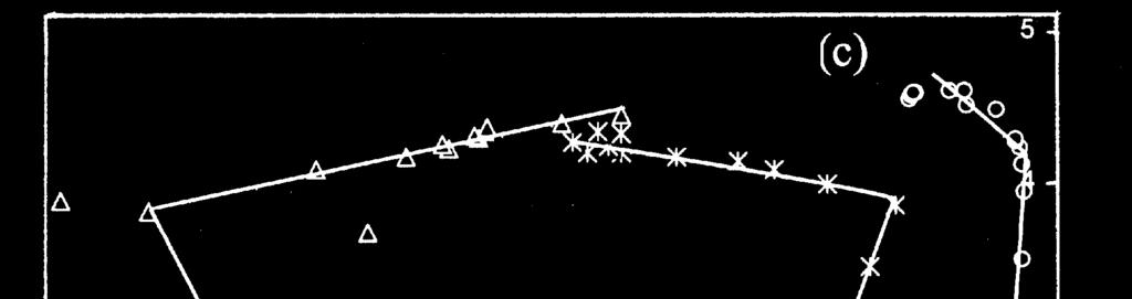
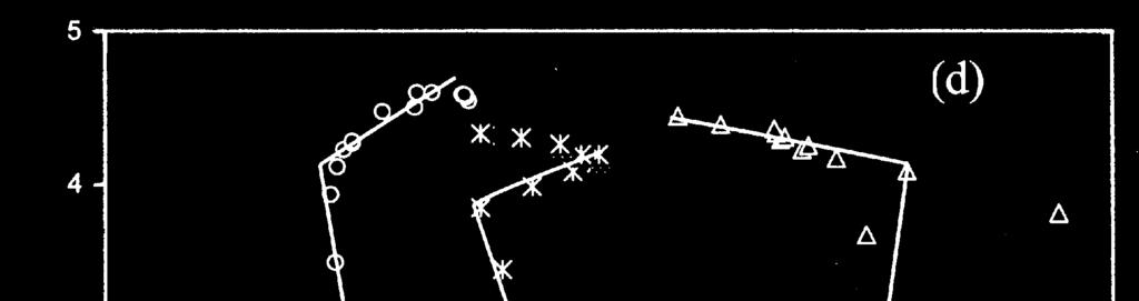
2 282 INDIAN J. ENG. MATER. SCI., AUGUST 2006 Experimental Procedure Cold upsetting specimens of 24 mm in diameter and of different heights corresponding to a set of aspect ratios (initial height to initial diameter ratio) namely 0.5, 0.75, and 1.0 were prepared by machining from 25 mm rods of commercially pure aluminium. These specimens were machined to different ratios of b/a (minor diameter/major diameter) namely 0.6 and 0.7.The cold upsetting of irregular shaped billets were conducted on a universal compression testing machine having capacity of 100 tons at room temperature with white grease as lubricant. For each test, nine specimens of the same dimensions were machined and deformed to different strain levels. The irregular shaped billets were upset between two flat platens. Extreme care is taken to place the specimens concentric with the axis of the platens. Before cold upsetting of the billets, the initial diameters such as major diameter (D o major ), minor diameter (D o minor ), initial height (h o ) of the specimens and the perimeter before deformation (P o ) were measured. After each incremental loading of deformation 3 metric tones the following parameters were measured: (i) Major top contact diameter (D TC Major ), (ii) Minor top contact diameter (D TC Minor ), (iii) Major bottom contact diameter (D BC Major ), (iv) Minor bottom contact diameter (D BC Minor ), (v) Major bulge diameter (D B Major), (vi) Minor bulge diameter (D B Minor ), (vii) Height after deformation (h f ), (viii) Area for top contact surface (A T ), (ix) Area for bottom contact surface (A B ), (x) Perimeter for top contact surface (P T ), (xi) Perimeter for bottom contact surface (P B ), (xii) Major radius of curvature (R m major ) and (xiii) Minor radius of curvature (R m minor ). The loads used for each deformation were recorded from the dial indicator of the universal compression testing machine. Major, minor contact diameters, bulge diameters, height before and after deformations were measured using a digital vernier caliper. Area, perimeter, bulge radius at each lubricated condition were recorded by scanning the irregular shaped billets using scanner. Further, the image was transferred to AutoCAD where the above said was measured. Fig. 1a shows the front view of the irregular shaped billet before deformation, where as Fig. 1b shows the shape after deformation. Figure 1c shows the photograph of undeformed irregular shaped billet samples of various heights. Figure 1d shows the photograph of deformed irregular shaped billet samples of various heights. Theoretical The mathematical expressions used and proposed for the determination of various upsetting stress parameters are discussed. Radius of the barrel As explained elsewhere 13, the expression for the circular radius of curvature of barrel is as follows: 2 x hf R = + (1) 2 8x where x ( D D ) =. Since x is very small, the B C /2 term 2 x can be neglected. Hence, Eq. (1) becomes R = h 4 D 2 f ( D ) B C (2) where, D B is the bulge diameter, D C is the contact diameter, and h f is the height after deformation. Uniaxial stress state condition The mathematical expressions used and proposed for the determination of various upsetting parameters of upsetting for various stress state conditions are discussed here. Fig. 1 Billet shape (a) before deformation and (b) after deformation
 undeformed and (d) deformed The state of stress in a homogeneous uniaxial compression process is as:")
 The axial strain is given as: where, ε x is the axial strain, ε is the hoop strain, P b is the perimeter after deformation,")
3 BASKARAN & NARAYANASAMY: COLD UPSET FORGING OF IRREGULAR SHAPED BILLETS 283 Fig. 1 Photograph of irregular shaped billet samples of aluminium for various height strains: (c) undeformed and (d) deformed The state of stress in a homogeneous uniaxial compression process is as: According to Abdel-Rahman et al. 14 = eff, r = = 0 (3) where, is the axial stress, eff is the effective stress, r is the radial stress, and is the hoop stress. Since = r = 0 for uniaxial, the hydrostatic stress is given by: 3 m = (4) The axial strain is given as: where, ε x is the axial strain, ε is the hoop strain, P b is the perimeter after deformation, and P 0 is the perimeter before deformation. Plane stress state condition According to Narayanasamy and Pandey 15, the state of stress in a plane stress state condition is as follows: 2 ( 0.5 ) 3( 1 ) 0.5 eff = +α +α+α where, ε eff is the effective stress. The axial stress is given as: C Z (7) Load = (8) A h 0 ε = ln hf The hoop stress is given as: P b ε = ln P0 (5) (6) where, is the axial stress, and A C is the contact area. Since r = 0 at the free surface, it follows from the flow rule that; 1+ 2α = 2 +α where, is the hoop stress. (9)
4 284 INDIAN J. ENG. MATER. SCI., AUGUST 2006 α= The Poisson's ratio is given as: ε 2 ε (10) where, α is the Poisson s ratio. Since the r = 0 in case of plane stress condition, the hydrostatic stress is given as: m = ( / )/3 (16) m For the known values of, the ratio can be determined. The effective stress component ( eff ) as explained elsewhere m = (11) The effective strain (ε eff ) is given as: 2 ( 0.5 ) 3 ( 1 ) 0.5 eff = +α +α+α Eq. (17) can be written as: Z (17) 2 ε = ε +ε +ε 3 ( ) eff r (12) where, ε is the axial strain, ε is the hoop strain and ε r is the radial strain. Here, ε r and ε are assumed to be equal for the determination of effective strain. Various stress ratio parameters under plane stress state condition Since the radial stress ( r ) is ero at the free surface, it follows from the flow rule that: 1+ 2α = 2 +α (13) where, is the hoop stress, is the axial stress and α is the Poisson s ratio. Eq. (13) can be written as: 1+ 2α = 2 +α (14) In the above equation, for the known values of α, the ratio can be determined. Since the radial stress ( r = 0) at the free surface, the hydrostatic stress ( m ) is given as: + 3 Eq. (15) can be written as: m = (15) eff 2 ( 0.5 ) 3( 1 ) 0.5 = +α +α+α (18) In the above equation, for the known values of α, eff the ratio can be determined. From Eqs (7) and (11), the ratio of eff can be determined. ( m / eff ) ( / ) m = eff eff (19) This section shows that stress ratio parameters like ( / ), ( m / ), ( eff / ), and ( m / eff ) can be determined from dimensional output. Results and Discussion Figures 2-5 have been plotted between the measured radius and the various stress ratio parameters namely ( / ), ( m / ), ( eff / ), and ( m / eff ) under plane stress condition for different aspect ratios (ratio of height to diameter), namely 0.5, 0.75 and 1.0 and for two different b/a ratios (ratio of minor diameter to major diameter) namely, 0.6 and 0.7. These plots have been made for the different barrel radii namely major and minor axis. The rate of change of barrel radius with respect to various stress ratio parameters is not same for all aspect ratios. This means that each aspect ratio has different slope. The barrel radius decreases very slowly with increasing stress ratio parameter in the case of higher aspect ratio when comparing with lower aspect ratios and the measured barrel radius remains almost constant, or
5 BASKARAN & NARAYANASAMY: COLD UPSET FORGING OF IRREGULAR SHAPED BILLETS 285 Fig. 2 Variation of measured radius (R m major) with respect to the stress ratio (a) /, (b) m /, (c) eff / and (d) m / eff, for b/a = 0.6 under plane stress condition [( ) h 0./d 0 =0.5, Fig. 3 Variation of measured radius (R m minor) with respect to the stress ratio (a) /, (b) m /, (c) eff / and (d) m / eff, for b/a = 0.6 under plane stress condition [( ) h 0./d 0 =0.5,
6 286 INDIAN J. ENG. MATER. SCI., AUGUST 2006 Fig. 4 Variation of measured radius (R m major) with respect to the stress ratio (a) /, (b) m /, (c) eff / and (d) m / eff, for b/a = 0.7 under plane stress condition [( ) h 0./d 0 =0.5, Fig. 5 Variation of measured radius (R m minor) with respect to the stress ratio (a) /, (b) m /, (c) eff / and (d) m / eff, for b/a = 0.7 under plane stress condition [( ) h 0./d 0 =0.5,
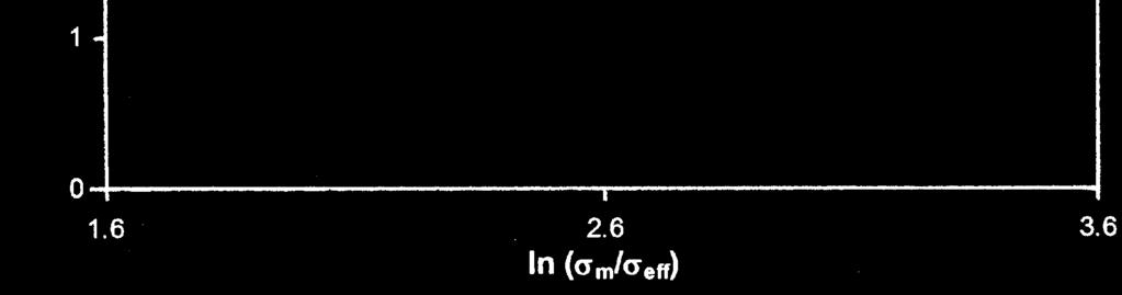
7 BASKARAN & NARAYANASAMY: COLD UPSET FORGING OF IRREGULAR SHAPED BILLETS 287 the radius of curvature decreases very slowly with increasing stress ratio parameter. This clearly indicated that, the rate of change of barrel radius with respect to the stress ratio parameters depends upon the ratio of b/a. Figures 6-9 have been plotted between the natural logarithm of the radius of curvature of the barrel and the natural logarithm of the stress ratio parameters namely ( / ), ( m / ), ( eff / ), and ( m / eff ) for plane stress stated condition for different aspect ratios and b/a ratios. These plots have been made for the different barrel radii (namely major axis and minor axis). These plots show that the rate of change of barrel radius with respect to the stress ratio parameter is different for different aspect ratios and b/a ratios. The variation in the slope value of the above straight lines is due to changes in shape of geometry. Figures 10 and 11 have been plotted between the percentage height reduction and the various stress ratio parameters namely ( / ), ( m / ), ( eff / ), and ( m / eff ) under plane stress condition for different aspect ratios and b/a ratios. For the increasing percentage height reduction, the stress ratio decreases rapidly in the case of higher aspect ratio when comparing with lower aspect ratio. This clearly indicates that there is a relationship between the percentage height reduction and stress ratio parameters. Figures 12 and 13 have been plotted between the natural logarithm of the variation of percentage height reduction and the natural logarithm of the stress ratio parameters namely ( / ), ( m / ), ( eff / ), and ( m / eff ) under plane stress condition for different aspect ratios and b/a ratios. The rate of change of height reduction with respect to the stress ratio is different for different aspect and (b/a) ratios. Fig. 6 ln Variation of measured radius (R m major) with respect to the ln stress ratio (a) /, (b) m /, (c) eff / and (d) m / eff, for b/a = 0.6 under plane stress condition [( ) h 0./d 0 =0.5,
8 288 INDIAN J. ENG. MATER. SCI., AUGUST 2006 Fig. 7 ln Variation of measured radius (R m minor) with respect to the ln stress ratio (a) /, (b) m /, (c) eff / and (d) m / eff, for b/a = 0.6 under plane stress condition [( ) h 0./d 0 =0.5, Fig. 8 ln Variation of measured radius (R m major) with respect to the ln stress ratio (a) /, (b) m /, (c) eff / and (d) m / eff, for b/a = 0.7 under plane stress condition [( ) h 0./d 0 =0.5,
9 BASKARAN & NARAYANASAMY: COLD UPSET FORGING OF IRREGULAR SHAPED BILLETS 289 Fig. 9 ln Variation of measured radius (R m minor) with respect to the ln stress ratio (a) /, (b) m /, (c) eff / and (d) m / eff, for b/a = 0.7 under plane stress condition [( ) h 0./d 0 =0.5, Fig. 10 Variation of percentage height reduction (h f ) with respect to the stress ratio (a) /, (b) m /, (c) eff / and (d) m / eff, for b/a = 0.6 under plane stress condition [( ) h 0./d 0 =0.5,


 m /, (c)")


10 290 INDIAN J. ENG. MATER. SCI., AUGUST 2006 [ Fig. 11 Variation of percentage height reduction (h f ) with respect to the stress ratio (a) /, (b) m /, (c) eff / and (d) m / eff, for b/a = 0.7 under plane stress condition [( ) h 0./d 0 =0.5, Fig. 12 ln Variation of percentage height reduction (h f ) with respect to the ln stress ratio (a) /, (b) m /, (c) eff / and (d) m / eff, for b/a = 0.6 under plane stress condition [( ) h 0./d 0 =0.5,
11 BASKARAN & NARAYANASAMY: COLD UPSET FORGING OF IRREGULAR SHAPED BILLETS 291 Fig. 13 ln Variation of percentage height reduction (h f ) with respect to the ln stress ratio (a) /, (b) m /, (c) eff / and (d) m / eff, for b/a = 0.7 under plane stress condition [( ) h 0./d 0 =0.5, Conclusions The following conclusions can be drawn from the present investigation: (i) The rate of change of measured barrel radius with respect to the stress ratio parameter is very high for lower aspect ratio (ratio of height to diameter). (ii) The rate of change of the percentage height reduction with respect to the stress ratio is different for different aspect ratios and b/a ratios. (iii) A straight-line relationship is established between the natural logarithm of percentage height reduction and stress ratio parameter with one or two different slopes for each aspect ratio and b/a ratio. Nomenclature a = major diameter b = minor diameter F = force h 0 D 0 h f D B D TC D BC = Initial height of the billet = Initial diameter of the billet = height of the billet after deformation = bulge diameter of the billet after deformation = top contact diameter of the billet after deformation = bottom contact diameter of the billet after deformation References 1 Lee C H & Altan T, ASME Trans, J Eng Ind, 94 (3) (1972) Hartley P, Sturgess C E N & Rowe G W, Int J Mech Sci, 22 (1980) Xue K M, Lu Y, Liu H H & Zhao X M, Adv Technol Plasticity II, (1993) Landre J, Pertence A, Cetlin P R, Rodrigues J M C & Martins P A F, J Finite Elements Anal Design, 39 (2003) Castro C F, Antonio C A C & Sousa L C, J Mater Process Technol, 146 (2004) Yang D Y & Kim J H, Int J Mach Tool Des Res, 26 (2) (1986)
12 292 INDIAN J. ENG. MATER. SCI., AUGUST Avitur B, Metal Forming: Process and Analysis, (McGraw- Hill Book Co., New York), 1968, Satsangi P S, Sharma P C & Prakash R, J Mater Process Technol, 136 (2003) Altan T, Computer simulation to predict load, stress and metal flow in an axisymmetric closed die forging, Metal forming, edited by Hoffmanner A L (Plenum Press, New York), 1971, Hill R, Lee E H & Tupper S J, Trans ASME, J Appl Mech, 73 (1951) Kudo H, Int J Mech Sci, 2 (1960) Manisekar K & Narayanasamy R, Int J Adv Manf Technol, 21 (2003) Malayappan S & Narayanasamy R, J Mater Sci Technol, 19 (2003) Abdel-Rahman M & El-Sheikh, J Mater Process Technol, 54 (1995) Narayanasamy R & Pandey K S, J Mater Process Technol, 70 (1997) Narayanasamy R, Senthil Kumar V & Pandey K S, Mech Mater, 38 (2006)
Optimization of blank dimensions to reduce springback in the flexforming process
 Journal of Materials Processing Technology 146 (2004) 28 34 Optimization of blank dimensions to reduce springback in the flexforming process Hariharasudhan Palaniswamy, Gracious Ngaile, Taylan Altan ERC
An Analytical Model for Long Tube Hydroforming in a Square Cross-Section Die Considering Anisotropic Effects of the Material
 Journal of Stress Analysis Vol. 1, No. 2, Autumn Winter 2016-17 An Analytical Model for Long Tube Hydroforming in a Square Cross-Section Die Considering Anisotropic Effects of the Material H. Haghighat,
Analysis of forming - Slab Method
 Analysis of forming - Slab Method Forming of materials is a complex process, involving either biaxial or triaxial state of stress on the material being formed. Analysis of the forming process, therefore
A novel technique of friction and material property measurement by tip test in cold forging
 A novel technique of friction and material property measurement by tip test in cold forging Y T Im*, S H Kang, and J S Cheon Department of Mechanical Engineering, Korea Advanced Institute of Science and
RESEARCH AND MEASUREMENTS OF VELOCITY FIELD DURING EXTRUSION PROCESS
 XIX IMEKO World Congress Fundamental and Applied Metrology September 6-11, 29, Lisbon, Portugal RESEARCH AND MEASUREMENTS OF VELOCITY FIELD DURING EXTRUSION PROCESS Leo Gusel 1, Rebeka Rudolf 1 1 Faculty
End forming of thin-walled tubes
 Journal of Materials Processing Technology 177 (2006) 183 187 End forming of thin-walled tubes M.L. Alves a, B.P.P. Almeida b, P.A.R. Rosa b, P.A.F. Martins b, a Escola Superior de Tecnologia e Gestão
Lecture #2: Split Hopkinson Bar Systems
 Lecture #2: Split Hopkinson Bar Systems by Dirk Mohr ETH Zurich, Department of Mechanical and Process Engineering, Chair of Computational Modeling of Materials in Manufacturing 2015 1 1 1 Uniaxial Compression
A study of forming pressure in the tube-hydroforming process
 Journal of Materials Processing Technology 192 19 (2007) 404 409 A study of forming pressure in the tube-hydroforming process Fuh-Kuo Chen, Shao-Jun Wang, Ray-Hau Lin Department of Mechanical Engineering,
An alternative design method for the double-layer combined die using autofrettage theory
 https://doi.org/10.5194/ms-8-267-2017 Author(s) 2017. This work is distributed under the Creative Commons Attribution.0 License. An alternative design method for the double-layer combined die using autofrettage
Prediction of geometric dimensions for cold forgings using the finite element method
 Journal of Materials Processing Technology 189 (2007) 459 465 Prediction of geometric dimensions for cold forgings using the finite element method B.Y. Jun a, S.M. Kang b, M.C. Lee c, R.H. Park b, M.S.
DIFFERENT TECHNIQUES FOR STRAIN ANALISYS IN METAL FORMING PROCESSES
 6th International DAAAM Baltic Conference INDUSTRIAL ENGINEERING 4-6 April 008, Tallinn, Estonia DIFFERENT TECHNIQUES FOR STRAIN ANALISYS IN METAL FORMING PROCESSES Leo Gusel, Rebeka Rudolf Abstract: Large
Burst pressure estimation of reworked nozzle weld on spherical domes
 Indian Journal of Engineering & Materials Science Vol. 21, February 2014, pp. 88-92 Burst pressure estimation of reworked nozzle weld on spherical domes G Jegan Lal a, Jayesh P a & K Thyagarajan b a Cryo
SHEAR STRENGTH OF SOIL UNCONFINED COMPRESSION TEST
 SHEAR STRENGTH OF SOIL DEFINITION The shear strength of the soil mass is the internal resistance per unit area that the soil mass can offer to resist failure and sliding along any plane inside it. INTRODUCTION
SIZE EFFECTS IN THE COMPRESSIVE CRUSHING OF HONEYCOMBS
 43rd AIAA/ASME/ASCE/AHS/ASC Structures, Structural Dynamics, and Materials Con 22-25 April 2002, Denver, Colorado SIZE EFFECTS IN THE COMPRESSIVE CRUSHING OF HONEYCOMBS Erik C. Mellquistand Anthony M.
Maejo International Journal of Science and Technology
 Maejo Int. J. Sci. Technol. 29, 3(2), 343-351 Full Paper Maejo International Journal of Science and Technology ISSN 195-7873 Available online at www.mijst.mju.ac.th Determination of proportionality constants
NORMAL STRESS. The simplest form of stress is normal stress/direct stress, which is the stress perpendicular to the surface on which it acts.
 NORMAL STRESS The simplest form of stress is normal stress/direct stress, which is the stress perpendicular to the surface on which it acts. σ = force/area = P/A where σ = the normal stress P = the centric
Development and analysis for the large-scale tee-forming process
 Journal of Materials Processing Technology 104 (2000) 265±270 Development and analysis for the large-scale tee-forming process Quang-Cherng Hsu a,*, Sio-Hou Lei b a Department of Mechanical Engineering,
Influence of impact velocity on transition time for V-notched Charpy specimen*
 [ 溶接学会論文集第 35 巻第 2 号 p. 80s-84s (2017)] Influence of impact velocity on transition time for V-notched Charpy specimen* by Yasuhito Takashima** and Fumiyoshi Minami** This study investigated the influence
CHAPTER 3 THE EFFECTS OF FORCES ON MATERIALS
 CHAPTER THE EFFECTS OF FORCES ON MATERIALS EXERCISE 1, Page 50 1. A rectangular bar having a cross-sectional area of 80 mm has a tensile force of 0 kn applied to it. Determine the stress in the bar. Stress
Analysis of forming- Slipline Field Method
 Analysis of forming- Slipline Field Method R. Chandramouli Associate Dean-Research SASTRA University, Thanjavur-613 401 Joint Initiative of IITs and IISc Funded by MHRD Page 1 of 7 Table of Contents 1.
Stresses Analysis of Petroleum Pipe Finite Element under Internal Pressure
 ISSN : 48-96, Vol. 6, Issue 8, ( Part -4 August 06, pp.3-38 RESEARCH ARTICLE Stresses Analysis of Petroleum Pipe Finite Element under Internal Pressure Dr.Ragbe.M.Abdusslam Eng. Khaled.S.Bagar ABSTRACT
ME 2570 MECHANICS OF MATERIALS
 ME 2570 MECHANICS OF MATERIALS Chapter III. Mechanical Properties of Materials 1 Tension and Compression Test The strength of a material depends on its ability to sustain a load without undue deformation
Simulation of the effect of DIE Radius on Deep Drawing Process
 Simulation the effect DIE Radius on Deep Drawing Process Kopanathi Gowtham, K.V.N.S. Srikanth & K.L.N. Murty CAD-CAM, Dept. Mechanical Engineering, Godavari Institute Engg. & Tech., Rajahmundry, India
Members Subjected to Torsional Loads
 Members Subjected to Torsional Loads Torsion of circular shafts Definition of Torsion: Consider a shaft rigidly clamped at one end and twisted at the other end by a torque T = F.d applied in a plane perpendicular
A FAILURE CRITERION FOR POLYMERS AND SOFT BIOLOGICAL MATERIALS
 Material Technology A FALURE CRTERON FOR POLYMERS AND SOFT BOLOGCAL MATERALS Authors: William W. Feng John O. Hallquist Livermore Software Technology Corp. 7374 Las Positas Road Livermore, CA 94550 USA
Plasticity R. Chandramouli Associate Dean-Research SASTRA University, Thanjavur
 Plasticity R. Chandramouli Associate Dean-Research SASTRA University, Thanjavur-613 401 Joint Initiative of IITs and IISc Funded by MHRD Page 1 of 9 Table of Contents 1. Plasticity:... 3 1.1 Plastic Deformation,
Mechanical Properties of Materials
 Mechanical Properties of Materials Strains Material Model Stresses Learning objectives Understand the qualitative and quantitative description of mechanical properties of materials. Learn the logic of
Analysis of Hydrodynamic Journal Bearing Using CFD and FSI Technique
 Analysis of Hydrodynamic Journal Bearing Using CFD and FSI Technique Priyanka Tiwari M.E. Student of Government Engineering College Jabalpur, M.P.-India Veerendra Kumar Principal of Government Engineering
Reference material Reference books: Y.C. Fung, "Foundations of Solid Mechanics", Prentice Hall R. Hill, "The mathematical theory of plasticity",
 Reference material Reference books: Y.C. Fung, "Foundations of Solid Mechanics", Prentice Hall R. Hill, "The mathematical theory of plasticity", Oxford University Press, Oxford. J. Lubliner, "Plasticity
Arch. Metall. Mater. 62 (2017), 3,
, 3,") Arch. Metall. Mater. 62 (2017), 3, 1881-1887 DOI: 10.1515/amm-2017-0285 P. RAMASWAMI* #, P. SENTHIL VELMURUGAN**, R. RAJASEKAR** EFFECT OF OVALITY IN INLET PIGTAIL PIPE BENDS UNDER COMBINED INTERNAL PRESSURE
Arch. Metall. Mater. 62 (2017), 3, 1881-1887 DOI: 10.1515/amm-2017-0285 P. RAMASWAMI* #, P. SENTHIL VELMURUGAN**, R. RAJASEKAR** EFFECT OF OVALITY IN INLET PIGTAIL PIPE BENDS UNDER COMBINED INTERNAL PRESSURE
Failure analysis of serial pinned joints in composite materials
 Indian Journal of Engineering & Materials Sciences Vol. 18, April 2011, pp. 102-110 Failure analysis of serial pinned joints in composite materials Alaattin Aktaş* Department of Mechanical Engineering,
Journal of Solid Mechanics and Materials Engineering
 and Materials Engineering Simulation of Friction in Hydrostatic Extrusion Process* Pankaj TOMAR**, Raj Kumar PANDEY*** and Yogendra NATH**** **MAE Department, GGSIPU (I.G.I.T.), Delhi, India E-mail: Pankaj_1343@rediffmail.com
The Rotating Inhomogeneous Elastic Cylinders of. Variable-Thickness and Density
 Applied Mathematics & Information Sciences 23 2008, 237 257 An International Journal c 2008 Dixie W Publishing Corporation, U. S. A. The Rotating Inhomogeneous Elastic Cylinders of Variable-Thickness and
Expansion of circular tubes by rigid tubes as impact energy absorbers: experimental and theoretical investigation
 Expansion of circular tubes by rigid tubes as impact energy absorbers: experimental and theoretical investigation M Shakeri, S Salehghaffari and R. Mirzaeifar Department of Mechanical Engineering, Amirkabir
Arch. Metall. Mater. 62 (2017), 1, 85-90
, 1, 85-90") Arch. Metall. Mater. 62 (2017), 1, 85-90 DOI: 10.1515/amm-2017-0011 Z. PATER* # FEM ANALYSIS OF LOADS AND TORQUE IN A SKEW ROLLING PROCESS FOR PRODUCING AXISYMMETRIC PARTS Skew rolling is a metal forming
Arch. Metall. Mater. 62 (2017), 1, 85-90 DOI: 10.1515/amm-2017-0011 Z. PATER* # FEM ANALYSIS OF LOADS AND TORQUE IN A SKEW ROLLING PROCESS FOR PRODUCING AXISYMMETRIC PARTS Skew rolling is a metal forming
Analysis of Tube End Formability of AA 2024 Tubes Using FEM
 International Journal of Current Engineering and Technology, Vol.2, No.1 (March 2012) ISSN 2277-4106 Research Article Analysis of Tube End Formability of AA 2024 Tubes Using FEM Bharathi. P a*, Venkateswarlu.
TORSION TEST. Figure 1 Schematic view of torsion test
 TORSION TEST 1. THE PURPOSE OF THE TEST The torsion test is performed for determining the properties of materials like shear modulus (G) and shear yield stress ( A ). 2. IDENTIFICATIONS: Shear modulus:
Lecture 8 Viscoelasticity and Deformation
 Read: pg 130 168 (rest of Chpt. 4) 1 Poisson s Ratio, µ (pg. 115) Ratio of the strain in the direction perpendicular to the applied force to the strain in the direction of the applied force. For uniaxial
Finite-Element Analysis of Stress Concentration in ASTM D 638 Tension Specimens
 Monika G. Garrell, 1 Albert J. Shih, 2 Edgar Lara-Curzio, 3 and Ronald O. Scattergood 4 Journal of Testing and Evaluation, Vol. 31, No. 1 Paper ID JTE11402_311 Available online at: www.astm.org Finite-Element
Friction Compensation in the Upsetting of Cylindrical Test Specimens
 Downloaded from orbit.dtu.dk on: Jan 22, 2019 Friction Compensation in the Upsetting of Cylindrical Test Specimens Christiansen, Peter; Martins, P. A. F.; Bay, Niels Oluf Published in: Experimental Mechanics
3D Finite Element Analysis of Drilling of Ti-6Al-4V Alloy
 International Conference on Computer Information Systems and Industrial Applications (CISIA 215) 3D Finite Element Analysis of Drilling of Ti-6Al-4V Alloy Y. Su, D.D. Chen, L. Gong College of Mechanical
INVERSE METHOD FOR FLOW STRESS PARAMETERS IDENTIFICATION OF TUBE BULGE HYDROFORMING CONSIDERING ANISOTROPY
 7 th EUROMECH Solid Mechanics Conference J. Ambrósio et.al. (eds.) Lisbon, Portugal, September 7-11, 2009 INVERSE METHOD FOR FLOW STRESS PARAMETERS IDENTIFICATION OF TUBE BULGE HYDROFORMING CONSIDERING
Size Effects In the Crushing of Honeycomb Structures
 45th AIAA/ASME/ASCE/AHS/ASC Structures, Structural Dynamics & Materials Conference 19-22 April 2004, Palm Springs, California AIAA 2004-1640 Size Effects In the Crushing of Honeycomb Structures Erik C.
Stress-Strain Behavior
 Stress-Strain Behavior 6.3 A specimen of aluminum having a rectangular cross section 10 mm 1.7 mm (0.4 in. 0.5 in.) is pulled in tension with 35,500 N (8000 lb f ) force, producing only elastic deformation.
Fatigue Damage Development in a Steel Based MMC
 Fatigue Damage Development in a Steel Based MMC V. Tvergaard 1,T.O/ rts Pedersen 1 Abstract: The development of fatigue damage in a toolsteel metal matrix discontinuously reinforced with TiC particulates
A parametric study on the elastic-plastic deformation of a centrally heated two-layered composite cylinder with free ends
 Arch. Mech., 68, 3, pp. 03 8, Warszawa 06 A parametric study on the elastic-plastic deformation of a centrally heated two-layered composite cylinder with free ends F. YALCIN ), A. OZTURK ), M. GULGEC 3)
Classical fracture and failure hypotheses
 : Chapter 2 Classical fracture and failure hypotheses In this chapter, a brief outline on classical fracture and failure hypotheses for materials under static loading will be given. The word classical
Influence of fibre proportion and position on the machinability of GFRP composites- An FEA model
 Indian Journal of Engineering & Materials Sciences Vol. 12, October 2005, pp. 443-450 Influence of fibre proportion and position on the machinability of GFRP composites- An FEA model D Abdul Budan* Department
Shock wave speed and stress-strain relation of aluminium honeycombs under dynamic compression
 EPJ Web of Conferences 83, 7 (8) DYMAT 8 https://doi.org/.5/epjconf/8837 Shock wave speed and stress-strain relation of aluminium honeycombs under dynamic compression Peng Wang,*, Jun Zhang, Haiying Huang,
G1RT-CT D. EXAMPLES F. GUTIÉRREZ-SOLANA S. CICERO J.A. ALVAREZ R. LACALLE W P 6: TRAINING & EDUCATION
 D. EXAMPLES 426 WORKED EXAMPLE I Flat Plate Under Constant Load Introduction and objectives Data Analysis Bibliography/References 427 INTRODUCTION AND OBJECTIVES During a visual inspection of a C-Mn flat
Tensile stress strain curves for different materials. Shows in figure below
 Tensile stress strain curves for different materials. Shows in figure below Furthermore, the modulus of elasticity of several materials effected by increasing temperature, as is shown in Figure Asst. Lecturer
DETERMINE PARAMETERS HYDROMECHANICAL BULGE FORMING AXISYMMETRIC COMPONENTS FROM COPPER TUBES. Tomasz Miłek
 DETERMINE PARAMETERS HYDROMECHANICAL BULGE FORMING AXISYMMETRIC COMPONENTS FROM COPPER TUBES Abstract Tomasz Miłek Kielce University of Technology, Faculty of Mechatronics and Machine Design, Department
FREE VIBRATION ANALYSIS OF THIN CYLINDRICAL SHELLS SUBJECTED TO INTERNAL PRESSURE AND FINITE ELEMENT ANALYSIS
 FREE VIBRATION ANALYSIS OF THIN CYLINDRICAL SHELLS SUBJECTED TO INTERNAL PRESSURE AND FINITE ELEMENT ANALYSIS J. Kandasamy 1, M. Madhavi 2, N. Haritha 3 1 Corresponding author Department of Mechanical
INDENTATION RESISTANCE OF AN ALUMINIUM FOAM
 Scripta mater. 43 (2000) 983 989 www.elsevier.com/locate/scriptamat INDENTATION RESISTANCE OF AN ALUMINIUM FOAM O.B. Olurin, N.A. Fleck and M.F. Ashby Cambridge University Engineering Department, Cambridge,
MECHANICS OF MATERIALS
 2009 The McGraw-Hill Companies, Inc. All rights reserved. Fifth SI Edition CHAPTER 3 MECHANICS OF MATERIALS Ferdinand P. Beer E. Russell Johnston, Jr. John T. DeWolf David F. Mazurek Torsion Lecture Notes:
Outline. Tensile-Test Specimen and Machine. Stress-Strain Curve. Review of Mechanical Properties. Mechanical Behaviour
 Tensile-Test Specimen and Machine Review of Mechanical Properties Outline Tensile test True stress - true strain (flow curve) mechanical properties: - Resilience - Ductility - Toughness - Hardness A standard
Influence of Back Pressure on Slab Edge Deformation Behavior during Width Reduction Pressing *1
 Materials Transactions, Vol. 57, No. 9 (2016) pp. 1567 to 1574 2016 The Japan Society for Technology of Plasticity Influence of Back Pressure on Slab Edge Deformation Behavior during Width Reduction Pressing
Prediction of Elastic Constants on 3D Four-directional Braided
 Prediction of Elastic Constants on 3D Four-directional Braided Composites Prediction of Elastic Constants on 3D Four-directional Braided Composites Liang Dao Zhou 1,2,* and Zhuo Zhuang 1 1 School of Aerospace,
Chapter 7. Highlights:
 Chapter 7 Highlights: 1. Understand the basic concepts of engineering stress and strain, yield strength, tensile strength, Young's(elastic) modulus, ductility, toughness, resilience, true stress and true
The objective of this experiment is to investigate the behavior of steel specimen under a tensile test and to determine it's properties.
 Objective: The objective of this experiment is to investigate the behavior of steel specimen under a tensile test and to determine it's properties. Introduction: Mechanical testing plays an important role
Experimental Investigation of Fully Plastic Contact of a Sphere Against a Hard Flat
 J. Jamari e-mail: j.jamari@ctw.utwente.nl D. J. Schipper University of Twente, Surface Technology and Tribology, Faculty of Engineering Technology, Drienerloolaan 5, Postbus 17, 7500 AE, Enschede, The
Module 5: Theories of Failure
 Module 5: Theories of Failure Objectives: The objectives/outcomes of this lecture on Theories of Failure is to enable students for 1. Recognize loading on Structural Members/Machine elements and allowable
A FINITE ELEMENT STUDY OF ELASTIC-PLASTIC HEMISPHERICAL CONTACT BEHAVIOR AGAINST A RIGID FLAT UNDER VARYING MODULUS OF ELASTICITY AND SPHERE RADIUS
 Proceedings of the International Conference on Mechanical Engineering 2009 (ICME2009) 26-28 December 2009, Dhaka, Bangladesh ICME09- A FINITE ELEMENT STUDY OF ELASTIC-PLASTIC HEMISPHERICAL CONTACT BEHAVIOR
Contact Modeling of Rough Surfaces. Robert L. Jackson Mechanical Engineering Department Auburn University
 Contact Modeling of Rough Surfaces Robert L. Jackson Mechanical Engineering Department Auburn University Background The modeling of surface asperities on the micro-scale is of great interest to those interested
Available online at ScienceDirect. Procedia Engineering 132 (2015 )
") Available online at www.sciencedirect.com ScienceDirect Procedia Engineering 132 (215 ) 326 333 The Manufacturing Engineering Society International Conference, MESIC 215 The Ring Compression Test: Analysis
Available online at www.sciencedirect.com ScienceDirect Procedia Engineering 132 (215 ) 326 333 The Manufacturing Engineering Society International Conference, MESIC 215 The Ring Compression Test: Analysis
Lecture #8: Ductile Fracture (Theory & Experiments)
") Lecture #8: Ductile Fracture (Theory & Experiments) by Dirk Mohr ETH Zurich, Department of Mechanical and Process Engineering, Chair of Computational Modeling of Materials in Manufacturing 2015 1 1 1 Ductile
Lecture #8: Ductile Fracture (Theory & Experiments) by Dirk Mohr ETH Zurich, Department of Mechanical and Process Engineering, Chair of Computational Modeling of Materials in Manufacturing 2015 1 1 1 Ductile
Numerical Assessment of the Influence of End Conditions on. Constitutive Behavior of Geomaterials
 Numerical Assessment of the Influence of End Conditions on Constitutive Behavior of Geomaterials Boris Jeremić 1 and Zhaohui Yang 2 and Stein Sture 3 ABSTRACT In this paper we investigate the behavior
MECHANICS OF MATERIALS Sample Problem 4.2
 Sample Problem 4. SOLUTON: Based on the cross section geometry, calculate the location of the section centroid and moment of inertia. ya ( + Y Ad ) A A cast-iron machine part is acted upon by a kn-m couple.
Design of a fastener based on negative Poisson's ratio foam adapted from
 1 Design of a fastener based on negative Poisson's ratio foam adapted from Choi, J. B. and Lakes, R. S., "Design of a fastener based on negative Poisson's ratio foam", Cellular Polymers, 10, 205-212 (1991).
Analytical and experimental evaluation of the stress-strain curves of sheet metals by hydraulic bulge tests
 Analytical and experimental evaluation of the stress-strain curves of sheet metals by hydraulic bulge tests Lucian LĂZĂRESCU 1, a, Dan-Sorin COMŞA 1,b and Dorel BANABIC 1,c 1 Technical University of Cluj-Napoca,
PROPAGATION OF CURVED CRACKS IN HOMOGENEOUS AND GRADED MATERIALS
 PROPAGATION OF CURVED CRACKS IN HOMOGENEOUS AND GRADED MATERIALS Abstract Matthew T. Tilbrook, Robert J. Moon and Mark Hoffman School of Materials Science and Engineering University of New South Wales,
Analytical Strip Method for Thin Isotropic Cylindrical Shells
 IOSR Journal of Mechanical and Civil Engineering (IOSR-JMCE) e-issn: 2278-1684,p-ISSN: 2320-334X, Volume 14, Issue 4 Ver. III (Jul. Aug. 2017), PP 24-38 www.iosrjournals.org Analytical Strip Method for
Determination of stress-strain curves of sheet metals by hydraulic bulge test
 Determination of stress-strain curves of sheet metals by hydraulic bulge test Lucian LĂZĂESCU, Dan Sorin COMŞA and Dorel BANABIC Technical University of Cluj-Napoca, Department of Manufacturing Engineering,
Hardened Concrete. Lecture No. 16
 Hardened Concrete Lecture No. 16 Fatigue strength of concrete Modulus of elasticity, Creep Shrinkage of concrete Stress-Strain Plot of Concrete At stress below 30% of ultimate strength, the transition
On fracture locus in the equivalent strain and stress triaxiality space
 International Journal of Mechanical Sciences 46 (2004) 81 98 On fracture locus in the equivalent strain and stress triaxiality space Yingbin Bao, Tomasz Wierzbicki Impact and Crashworthiness Laboratory,
EFFECT OF STRAIN HARDENING ON ELASTIC-PLASTIC CONTACT BEHAVIOUR OF A SPHERE AGAINST A RIGID FLAT A FINITE ELEMENT STUDY
 Proceedings of the International Conference on Mechanical Engineering 2009 (ICME2009) 26-28 December 2009, Dhaka, Bangladesh ICME09- EFFECT OF STRAIN HARDENING ON ELASTIC-PLASTIC CONTACT BEHAVIOUR OF A
On the Path-Dependence of the J-Integral Near a Stationary Crack in an Elastic-Plastic Material
 Dorinamaria Carka Chad M. Landis e-mail: landis@mail.utexas.edu Department of Aerospace Engineering and Engineering Mechanics, University of Texas at Austin, 10 East 4th Street, C0600 Austin, TX 7871-035
Identification of model parameters from elastic/elasto-plastic spherical indentation
 Thomas Niederkofler a, Andreas Jäger a, Roman Lackner b a Institute for Mechanics of Materials and Structures (IMWS), Department of Civil Engineering, Vienna University of Technology, Vienna, Austria b
Chapter 3. Load and Stress Analysis
 Chapter 3 Load and Stress Analysis 2 Shear Force and Bending Moments in Beams Internal shear force V & bending moment M must ensure equilibrium Fig. 3 2 Sign Conventions for Bending and Shear Fig. 3 3
DETERMINATION OF THE EFFECTIVE STRAIN FLOW IN COLD FORMED MATERIAL
 DETERMINATION OF THE EFFECTIVE STRAIN FLOW IN COLD FORMED MATERIAL Leo Gusel University of Maribor, Faculty of Mechanical Engineering Smetanova 17, SI 000 Maribor, Slovenia ABSTRACT In the article the
Influence of roughness parameters on coefficient of friction under lubricated conditions
 Sādhanā Vol. 33, Part 3, June 2008, pp. 181 190. Printed in India Influence of roughness parameters on coefficient of friction under lubricated conditions PRADEEP L MENEZES 1, KISHORE 1 and SATISH V KAILAS
A slip-line solution to metal machining using a cutting tool with a step-type chip-breaker
 Journal of Materials Processing Technology 79 (1998) 217 223 A slip-line solution to metal machining using a cutting tool with a step-type chip-breaker K.P. Maity *, N.S. Das Department of Mechanical Engineering,
Experimental investigations of different force measuring systems
 Indian Journal Pure & Applied Physics Vol. 51, June 2013, pp. 393-398 Experimental investigations different force measuring systems Harish Kumar 1,2 * & Chitra Sharma 3 1 CSIR-National Physical Laboratory,
A New Method for Correcting the Stress-Strain Curves after Bulging in Metals
 Journal of Stress Analysis Vol. 1, No. 2, Autumn Winter 2016-17 A New Method for Correcting the Stress-Strain Curves after Bulging in Metals F. Fariba a,, M. Ahmadpour a, H. Bahrami b a Mechanical Engineering
EMA 3702 Mechanics & Materials Science (Mechanics of Materials) Chapter 2 Stress & Strain - Axial Loading
 Chapter 2 Stress & Strain - Axial Loading") MA 3702 Mechanics & Materials Science (Mechanics of Materials) Chapter 2 Stress & Strain - Axial Loading MA 3702 Mechanics & Materials Science Zhe Cheng (2018) 2 Stress & Strain - Axial Loading Statics
MA 3702 Mechanics & Materials Science (Mechanics of Materials) Chapter 2 Stress & Strain - Axial Loading MA 3702 Mechanics & Materials Science Zhe Cheng (2018) 2 Stress & Strain - Axial Loading Statics
Experimental and analytical studies on the pullout strength of round thread casing connections
 Indian Journal of Engineering & Materials Science Vol. 20, December 2013, pp. 497-503 Experimental and analytical studies on the pullout strength of round thread casing connections Lianxin Gao a * & Jiaoqi
PVD COATING AND UP-TO-DATE WEAR TEST OF HOT-FORMING TOOLS
 HUNGARIAN JOURNAL OF INDUSTRY AND CHEMISTRY VESZPRÉM Vol. 40() pp. 9 4 (0) PVD COATING AND UP-TO-DATE WEAR TEST OF HOT-FORMING TOOLS F. TÁNCSICS,, E. HALBRITTER Széchenyi István University, Department
Stress and fabric in granular material
 THEORETICAL & APPLIED MECHANICS LETTERS 3, 22 (23) Stress and fabric in granular material Ching S. Chang,, a) and Yang Liu 2 ) Department of Civil Engineering, University of Massachusetts Amherst, Massachusetts
Introduction to Engineering Materials ENGR2000. Dr. Coates
 Introduction to Engineering Materials ENGR2 Chapter 6: Mechanical Properties of Metals Dr. Coates 6.2 Concepts of Stress and Strain tension compression shear torsion Tension Tests The specimen is deformed
Volume 2 Fatigue Theory Reference Manual
 Volume Fatigue Theory Reference Manual Contents 1 Introduction to fatigue 1.1 Introduction... 1-1 1. Description of the applied loading... 1-1.3 Endurance curves... 1-3 1.4 Generalising fatigue data...
Module-4. Mechanical Properties of Metals
 Module-4 Mechanical Properties of Metals Contents ) Elastic deformation and Plastic deformation ) Interpretation of tensile stress-strain curves 3) Yielding under multi-axial stress, Yield criteria, Macroscopic
Lecture #10: Anisotropic plasticity Crashworthiness Basics of shell elements
 Lecture #10: 151-0735: Dynamic behavior of materials and structures Anisotropic plasticity Crashworthiness Basics of shell elements by Dirk Mohr ETH Zurich, Department of Mechanical and Process Engineering,
1. Background. is usually significantly lower than it is in uniaxial tension
 NOTES ON QUANTIFYING MODES OF A SECOND- ORDER TENSOR. The mechanical behavior of rocks and rock-like materials (concrete, ceramics, etc.) strongly depends on the loading mode, defined by the values and
Predicting the shear strength of round clinched joint
 Indian Journal of Engineering & Materials Sciences Vol. 21, October 2014, pp. 510-518 Predicting the shear strength of round clinched joint F Xu a,b & S D Zhao a * a School of Mechanical Engineering, Xi
The Ultimate Load-Carrying Capacity of a Thin-Walled Shuttle Cylinder Structure with Cracks under Eccentric Compressive Force
 The Ultimate Load-Carrying Capacity of a Thin-Walled Shuttle Cylinder Structure with Cracks under Eccentric Compressive Force Cai-qin Cao *, Kan Liu, Jun-zhe Dong School of Science, Xi an University of
A multiscale framework for lubrication analysis of bearings with textured surface
 A multiscale framework for lubrication analysis of bearings with textured surface *Leiming Gao 1), Gregory de Boer 2) and Rob Hewson 3) 1), 3) Aeronautics Department, Imperial College London, London, SW7
7.6 Stress in symmetrical elastic beam transmitting both shear force and bending moment
 7.6 Stress in symmetrical elastic beam transmitting both shear force and bending moment à It is more difficult to obtain an exact solution to this problem since the presence of the shear force means that
Effect of uniform and gradient thermal loadings on cylindrical steel reservoirs (analytical investigation)
") Journal of Civil Engineering and Construction Technology Vol. (3), pp. 9-3, March 13 Available online at http://www.academicjournals.org/jcect DOI:.597/JCECT1.91 ISS 11-3 13 Academic Journals Full Length
Journal of Civil Engineering and Construction Technology Vol. (3), pp. 9-3, March 13 Available online at http://www.academicjournals.org/jcect DOI:.597/JCECT1.91 ISS 11-3 13 Academic Journals Full Length
4.MECHANICAL PROPERTIES OF MATERIALS
 4.MECHANICAL PROPERTIES OF MATERIALS The diagram representing the relation between stress and strain in a given material is an important characteristic of the material. To obtain the stress-strain diagram
Structural Metals Lab 1.2. Torsion Testing of Structural Metals. Standards ASTM E143: Shear Modulus at Room Temperature
 Torsion Testing of Structural Metals Standards ASTM E143: Shear Modulus at Room Temperature Purpose To determine the shear modulus of structural metals Equipment Tinius-Olsen Lo-Torq Torsion Machine (figure