Measurement Systems. Lecture 7- Combination of Component Errors in Overall System-Accuracy Calculations
|
|
|
- Maud Garrett
- 5 years ago
- Views:
Transcription
1 Measurement Systems Lecture 7- Combination of Component Errors in Overall System-Accuracy Calculations Hamid Ahmadian School of Mechanical Engineering Iran University of Science and Technology
2 Combination of Component Errors in Overall System-Accuracy Calculations When planning an experiment, we must decide how accurate the final results must be to meet the goals of the study. The method of equal effects: it seems reasonable to, at least initially, force all the instruments to contribute equally to the overall error.
3 An example: Dynamometer Consider an experiment for measuring, by means of a dynamometer, the average power transmitted by a rotating shaft.
4 Uncertainties for each item Our preference, is to treat uncertainty at the 95 percent level of confidence. It is assumed the counter does not miss any counts, the maximum error in R is ±1, because of the digital nature of the device. In assigning an error to t, the synchronization error is considered which involves human factors; a total starting and stopping error is taken as ±0.50 s
5 Uncertainties for each item The measurement of the torque arm length L with 95 percent uncertainty is assigned ±0.05 in. The scales used to measure the force F is calibrated with deadweights, yielding an uncertainty ±0.040
6 Uncertainties for each item The calibration uncertainty must be translated into a corresponding measurement uncertainty, the scales is subject to vibration (not present at calibration), which may reduce frictional effects and decrease the error (uncertainty). the pointer on the scale will not stand perfectly still when the dynamometer is running; thus may introduce a new error not present at calibration. Suppose we assume the two mentioned effects cancel and thus take the force measurement uncertainty as ± lbf.
7 Most sensitive parameters Absolute error The total uncertainty
8 An example: Dynamometer Suppose we wish to measure hp to 0.5 percent accuracy; what accuracies are needed in the individual measurements? Most sensitive parameters Where possible one or more of the quantities, R, F, L, and t must be measured more accurately.
9 Theory Validation by Experimental Testing An important application of experimental work is testing of new theoretical relations Such confirmation is usually of a statistical nature; both the theoretical prediction and the experimental measurement have some uncertainty attached to them. An "overlap graph" of the theoretical and the measured results, each with its own uncertainty band reviles correlations between two sets. When there is some overlap, then the theory gets more and more likely to be correct as the overlap region increases.
10 Theory Validation by Experimental Testing: An Example To check the thin beam theory we might build a beam with certain properties (L, b, t, E). We then apply a force F and measure the resulting δ. Suppose our interest is in the "spring constant" F/δ. Measuring F, δ and estimates of their 95 percent confidence interval lead to computation of the uncertainty in the ratio F/δ.
11 Theory Validation by Experimental Testing: An Example Every "theoretical" result relies on one or more parameter values that can only be found by "experiment", we need values for the dimensions and the material property E. these can only be found by experiment! we can as usual attach an uncertainty to each. We calculate the uncertainty in the theoretical value, and plot the "overlap graph". Inaccurate as shearing effects are neglected!!!
12 Effect of Measurement Error on Quality- Control Decisions in Manufacturing All measurement systems exhibit statistical scatter; resulting partially defeat of our qualitycontrol goals. some good product may be measured as bad and some bad product may be measured as good. If both the process and measurement variabilities are assumed to be Gaussian, statistical analysis can be used to quantify these effects.
13 Effect of Measurement Error on Quality- Control Decisions in Manufacturing The "gage" (dashed curves) is set to reject product which measures below 4 and above 16. Due to measurement errors, some percentage of bad product will be measured as good and vice versa, as shown by the shaded squares. We can bias our gage limits, that is, we choose to reject units which measure as large as say, 6, and as small as 14. Then the chance of accepting bad product is nearly zero. Of course the price we pay is that now we will be rejecting more good product. target acceptable range
14 Effect of Measurement Error on Quality- Control Decisions in Manufacturing Quality-control managers have to decide where to strike a balance between these conflicting goals. The effect of measurement errors can usually be ignored if the measurement system standard deviation is less than about 4 percent of the product acceptance range, Here the percentage is 0.5/(16-4) = 4.2%, so this example almost meets the criterion target acceptable range
15 Measurement Systems Lecture 8- Static Characteristics (Cont.) Hamid Ahmadian School of Mechanical Engineering Iran University of Science and Technology
16 Static Characteristics (Cont.) Static Sensitivity Computer-Aided Calibration and Measurement: Multiple Regression Linearity Threshold, Noise Floor, Resolution, Hysteresis, and Dead Space Scale Readability Span Generalized Static Stiffness and Input Impedance: Loading Effects
17 Static Sensitivity The static sensitivity of the instrument can be defined as the slope of the calibration curve. If the curve is not nominally a straight line, the sensitivity will vary with the input value. To get a meaningful definition of sensitivity, the output quantity must be taken as the actual physical output, not the meaning attached to the scale numbers, In this form the sensitivity allows comparison of different instruments as regards their ability to detect measurand changes.
18 Static Sensitivity Sensitivity to interfering and/or modifying inputs is also of interest. Temperature can cause a relative expansion/contraction in a pressure gage (an interfering input). Also, temperature can alter the modulus of elasticity of the pressure-gage spring, thereby affecting the pressure sensitivity (a modifying input). The first effect is often called a zero drift while the second is a sensitivity drift or scale-factor drift. The superposition of these two effects determines the total error due to temperature. numerical knowledge of zero drift and sensitivity drift allows correction of the readings If such corrections are not feasible, then knowledge of the drifts is used mainly to estimate overall system errors due to temperature
19 Static Sensitivity To evaluate zero drift, the pressure is held at zero while the temperature is varied over a range and the output reading recorded. For reasonably small temperature ranges, the effect is often nearly linear Sensitivity drift may be found by fixing the temperature and running a pressure calibration to determine pressure sensitivity. Repeating this for various temperatures should show the effect of temperature on pressure sensitivity.
20 Computer-Aided Calibration and Measurement: Multiple Regression A more cost/effective approach uses multipleregression statistical techniques rather than the classical "one variable at a time. Consider an example where we want to cover a temperature range of 40 to 100 F (the design temperature is 70 F) and the range of the pressure transducer is from 0 to 100 psig. In laying out the calibration plan, we must choose the total number of runs and also the specific combinations of pressure and temperature to actually use.
21 Computer-Aided Calibration and Measurement: Multiple Regression Assume that the pressure transducer output voltage e 0 is given in terms of pressure p and temperature T by If our model and data were perfect, it would require only four sets of p, T, and e o measurements to find the parameter values (four equations in four unknowns)
22 Computer-Aided Calibration and Measurement: Multiple Regression Exact Model Identified Models (in presence of noise effects)

23 Computer-Aided Calibration and Measurement: Multiple Regression the 9 runs we have decided to try validation experiment
24 Linearity If an instrument's calibration curve for desired input is not a straight line, the instrument may still be highly accurate. Specifications relating to the degree of conformity to straight-line behavior are common. The conversion from a scale reading to the corresponding measured value of input quantity is most convenient if we merely have to multiply by a fixed constant. When the instrument is part of a larger data or control system, linear behavior of the parts often simplifies design and analysis of the whole.
25 Linearity Several definitions of linearity are possible. However, independent nonlinearity seems to be preferable in many cases, A measure of the maximum deviation of any calibration points from this straight line.
26 Hysteresis, and Dead Space Overall hysteresis effect Internal friction / hysteretic damping External sliding friction
27 Generalized Static Stiffness and Input Impedance: Loading Effects The introduction of any measuring instrument into a measured medium always results in the extraction of some energy from the medium, thereby changing the value of the measured quantity from its undisturbed state and thus making perfect measurements theoretically impossible. Should be minimized by impedance matching of source with measuring instrument.
28 Generalized Static Stiffness and Input Impedance: Loading Effects P E 2 / Z2 Input Impedance Measured source voltage potential The more Z 2 / Z 1 is, the less the loading error
29 Example: 3.1A force-measuring transducer has an opencircuit output voltage of 95 mv and an output impedance of 500 Ω. To amplify the signal voltage, it is connected to an amplifier with a gain of 10. Estimate the input loading error if the amplifier has an input impedance of: (a) 4 kω or (b) 1 MΩ.

30 Solution: a) Solving for the current yields The voltage across the amplifier input resistor is then The loading error is thus 10.6 m V or 11 % of the transducer unloaded output. b) Repeating the analysis replacing the 4-k Ω resistor with a 1-M Ω resistor, the error becomes mv or 0.05%.
31 Measurement Systems Lecture 9- DYNAMIC CHARACTERISTICS Hamid Ahmadian School of Mechanical Engineering Iran University of Science and Technology

32 Dynamic Characteristics Dynamic characteristics tell us about how well a sensor responds to changes in its input. For dynamic signals, the sensor or the measurement system must be able to respond fast enough to keep up with the input signals. In many situations, we must use q o (t) to infer q i (t), A qualitative understanding of the operation that the sensor or measurement system performs is imperative to understanding the input signal correctly.
33 Generalized Mathematical Model of Measurement System The most widely useful mathematical model for the study of measurement-system dynamic response is the ordinary linear differential equation with constant coefficients. The relation between any particular input (desired, interfering, or modifying) and the output can be put in the form:
34 Operational Transfer Function In the analysis, design, and application of measurement systems, the concept of the operational transfer function is very useful: Their utility for graphic symbolic depiction of system dynamic characteristics by means of block diagrams, It is helpful in determining the overall characteristics of a system made up of components whose individual transfer functions are known

35 Forcing functions The typical ones for dynamic response analysis :

36 Characteristic Equation Development Nature of characteristic equation block behavior Highest order usually necessary to consider in first-cut instrument analysis : 2nd-order class


37 Zero-order blocks No frequency dependent term Not even for phase shift Just For amplification ( ) a 0 7
38 First-Order Systems A system where energy is stored (or dissipated) A change at the input is NOT seen immediately at the output. Many instruments exhibit a 1 st order response. Thermal Systems Digital filters Analog filters Capacitances
39 First Order Systems: Provides a parameter, called the time constant, for choosing an instrument. This parameter let us know if the instrument will respond quick enough to capture changes in the system. a 1 dy a dt 0 y bx
40 ()First-Order Systems: Step Input Conservation of Energy Rate of energy added Rate of energy removed = Rate of energy change within system (CV) E s SyE out E stemhatts dedtcv d dsystemeout dtdcvcvdthaddhatt ( )Tdt T s T A s TTT 1 st order ODE hs T = T(t) T(0) = T o >T cvae cvt
41 TTo T T e R = Thermal resistance C = Thermal capacity c v has RC Response for Varying Values of Tau 1 R ha s C c v T T o T T Tau = 1 Tau = 0.5 Tau = Time 11 K. Alt
(tettttto 0.632 or 63.2% 0.")
42 12 1 M T T T T M M T o o 10,RatioMagnitude01,inErorDynamic5 )(tettttto or 63.2% % of the final value Rise Time
43 Time Constant Is the time it takes a first order system to reach 63.2% (0.632) of its final value in response to a step change in the system Time
44 First-order blocks Time dependent terms Output response to step forcing function y( t) AK(1 e t / ) Static gain of the block Step amplitude 14
45 Example A balloon is equipped with temperature and altitude measuring instruments. The balloon is initially anchored to the ground with the instrument output readings in steady state. The altitude-measuring instrument is approximately zero order and the temperature transducer first order with a time constant of 15 seconds. The temperature on the ground, T 0, is 10 C and the temperature T x at an altitude of x meters is given by the relation: T x = T x
46 Example a) If the balloon is released at time zero, and thereafter rises upwards at a velocity of 5 m/sec, draw a table showing the temperature and altitude measurements at intervals of 10 seconds over the first 50 seconds of travel. Show also in the table the error in each temperature reading. b) What temperature does the balloon report at an altitude of 5000 meters?
47 Solution of part a) Tx T0 0.01x x Tr 1 D 1 D 1 15D t/15 T Ce ( t 15) t 0., T 10 C 0.75 r
48 Solution of Part mt, 1000sec T T r r 1000/ e For large values of t, the transducer reading lags the true temperature value by a period of time equal to the time constant of 15 seconds. o C
49 First-order blocks Output response to sine-wave forcing function amplitude of the steady state response phase shift Dynamic error: a measure of an inability of a system to adequately reconstruct the amplitude of the input for a particular frequency 19
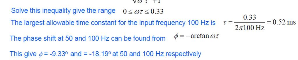
50 First-Order Systems: Frequency Response Example Suppose we want to measure the following input signal with a first-order instrument whose τ is 0.2 s and static sensitivity K, Solution: By superposition, one can write,
51 Dynamic Characteristics
52 Dynamic Characteristics

53 Dynamic Characteristics

54 Dynamic Characteristics Example: The approximate time constant of a thermometer is determined by immersing it in a bath and noting the time it takes to reach 63% of the final reading. If the result is 28 s, determine the delay when measuring the temperature of a bath that is periodically changing 2 times per minute.
55 Measurement Systems Lecture 10- Dynamic Characteristics (cont.) Hamid Ahmadian School of Mechanical Engineering Iran University of Science and Technology
56 Second-Order Systems In general, a second-order measurement system subjected to arbitrary input, x(t): The essential parameters:
57 Second-Order Systems The characteristic equation: Roots of quadratic equation: Complementary solutions:

58 Second-order Systems: Example: The force-measuring spring Consider a spring with spring constant Ks under applied force fi and the total mass M. At start, the scale is adjusted so that xo =0 when fi =0;
59 Second-order Systems: Step Response With zero initial conditions:
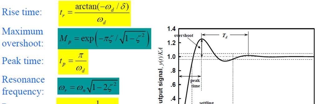
60 Second-order Systems: Step Response Non-dimensional step response of second-order instrument
61 Second-order Systems: Step Response For over-damped (ζ >1) or critical damped (ζ = 1), there is neither overshoot nor steady state dynamic error in the response. In an under-dameped system (ζ < 1) the steady-state dynamic error is zero, but the speed and overshoot in the transient are related.
62 Second-order Systems: Step Response
63 Second-order Systems: Ramp Response For a ramp input: With zero initial conditions the solutions are:
64 Second-order Systems: Ramp Response Typical ramp response of second-order instrument
65 Second-order Systems: Frequency Response The response of a second-order to a sinusoidal input
66 Example: A pressure transducer has a natural frequency of 30 rad/s, damping ratio of 0.1 and static sensitivity of 1.0 μv/pa. A step pressure input of 8*10 5 N/m 2 is applied. Determine the output of a transducer. Solution:
67 Example: A second order instrument is subjected to a sinusoidal input. Undamped natural frequency is 3 Hz and damping ratio is 0.5. Calculate the amplitude ratio and phase angle for an input frequency of 2 Hz. Solution:
68 Example: An Accelerometer is to selected to measure a timedependent motion. In particular, input signal frequencies below 100 Hz are of prime interest. Select a set of acceptable parameter specifications for the instrument, assuming a dynamic error of ±5% and damping ratio ζ =0.7


69 Response of a General Form of System to a Periodic Input The steady state response of any linear system to the complex periodic signal can be determined using the frequency response technique and principle of superposition.
70 Response of a General Form of System of a Periodic Input
71 Response of a General Form of System to a Periodic Input
72 Measurement Systems Lecture 11- Measuring Devices Hamid Ahmadian School of Mechanical Engineering Iran University of Science and Technology
73 Motion and Dimensional Measurement Considering measuring devices with motion and dimensional measurements as, they are based on two of the fundamental quantities in nature (length and time), so many other quantities (such as force, pressure, temperature, etc.) are often measured by transducing them to motion and then measuring this resulting motion. Mainly concerned with electromechanical transducers which convert motion quantities into electrical quantities, To provide sufficient detail for practical application of the relatively small number of transducer types which form the basis of the majority of practical measurements.
74 Motion and Dimensional Measurement Fundamental Standards Relative Displacement: Translational and Rotational Calibration Resistive Potentiometers Resistance Strain Gage Differential Transformers Synchros and Resolvers Variable-Inductance and Variable-Reluctance Pickups Eddy-Current Non-contacting Transducers Capacitance Pickups Piezoelectric Transducers Electro-Optical Devices Photographic and Electronic- Imaging Techniques Photoelastic, Brittle-Coating, and Moire Fringe Stress-Analysis Techniques Displacement-to-Pressure (Nozzle- Flapper) Transducer Digital Displacement Transducers (Translational and Rotary Encoders) Ultrasonic Transducers
75 FUNDAMENTAL STANDARDS In the SI system, there are seven basic measurement units from which all other units are derived,
76 Derived Standards All of the other units are derived from the seven basic units,
77 RELATIVE DISPLACEMENT: TRANSLATIONAL AND ROTATIONAL We consider here devices for measuring, the translation along a line of one point relative to another and the plane rotation about a single axis of one line relative to another. They form the basis of many transducers for measuring pressure, force, acceleration, temperature, etc.

78 Calibration Static calibration of translational devices often can be satisfactorily accomplished by using ordinary micrometers as the standard A precision dividing head may be used to both produce the angular motion and measure it.
79 Resistive Potentiometers A resistive potentiometer consists of a resistance element provided with a movable contact. The contact motion can be translation, rotation, or a combination of the two (helical motion in a multi turn rotational device), Allowing measurement of rotary and translatory displacements. The resistance element is excited with either de or ac voltage, and the output voltage is (ideally) a linear function of the input displacement.


80 Resistive Potentiometers Ex.: It is necessary to measure the position of a panel. It moves 0.8 m. Its position must be know within 0.1 cm. Part of the mechanism which moves the panel is shaft that rotate 250 o when Panel is moved from one extreme to the other. A control potential has been found which is rated at 300 o full scale movement. It has been 1000 turns of wire. Can this be used? Solution: Potentiometer resolution is, The shaft provides a conversion, The required resolution translates into, So the available potentiometer will work.
81 Resistive Potentiometers Self-heating occurs because of the power dissipation in sensor. The increase in temperature from self-heating ΔT due to P D =I 2 R T is: δ is heat dissipation factor (mw/k) θ is thermal resistance (K/mW) To minimize self-heating effect, the power dissipation must be limited.
82 Resistive Potentiometers Ex: A control potentiometer is rated as 150 Ω 1 W (derate at 10 mw/ o Cabove 65 o C) 30 o C/W thermal resistance Can it be used with 10 V supply at 80 o C ambient temperature? Solution: The power dissipated by the potentiometer is, The actual temperature of the potentiometer The allowable power dissipation P allowed < P
83 Resistive Potentiometers The potentiometer output voltage is the input to a meter or recorder that draws some current from the potentiometer. Potentiometer loading effect causes:

84 Resistive Potentiometers Ex.: Plot the transfer curve and determine endpoint linearity of a 1 kω potential driving a 5 kω load, powered from a 10 V source.
85 Resistive Potentiometers
86 Resistive Potentiometers
87 Resistance Strain Gage Consider a conductor of area A and length L, made of a material with resistivity ρ. The resistance R is given by: If this conductor is now stretched or compressed, its resistance will change Neglecting higher orders
88 Resistance Strain Gage Strain gages, in general, are applied in two types of tasks: in experimental stress analysis of machines and structures and in construction of force, torque, pressure, flow, and acceleration transducers.

89 Resistance Strain Gage

90 Resistance Strain Gage
91 Wheatstone Bridge: Deflection Method Wheatstone bridges are often used in the deflection mode: This method measures the voltage difference between both dividers or the current through a detector bridging them.
92 Temperature Compensation

93 Temperature Compensation
94 Strain gage arrangements
95 Effect of Lead Wire Resistance
96 Effect of Lead Wire Resistance: Defection method


97 Effect of Lead Wire Resistance: Defection method

98 Load Cell
99 Load Cell
100 Differential Transformers Schematic and circuit diagrams for translational and rotational linear variable-differentialtransformer (LVDT) displacement pickups
101 Differential Transformers When the secondaries are connected in series opposition, a null position exists e 0 is zero. Motion of the core from null then causes a larger mutual inductance (coupling) for one coil and a smaller mutual inductance for the other, the amplitude of e 0 becomes a nearly linear function of core position for a considerable range either side of null.
102 Differential Transformers The output e 0 is generally out of phase with the excitation e ex inductances no voltage-measuring device attached For each differential transformer there exists a particular frequency (numerical value supplied by the manufacturer) at which this phase shift is zero.
103 Measurement Systems Lecture 12- Measuring Devices (Contd.) Hamid Ahmadian School of Mechanical Engineering Iran University of Science and Technology
104 Motion and Dimensional Measurement Fundamental Standards Relative Displacement: Translational and Rotational Calibration Resistive Potentiometers Resistance Strain Gage Differential Transformers Synchros and Resolvers Variable-Inductance and Variable-Reluctance Pickups Eddy-Current Non-contacting Transducers Capacitance Pickups Piezoelectric Transducers Electro-Optical Devices Photographic and Electronic- Imaging Techniques Photoelastic, Brittle-Coating, and Moire Fringe Stress-Analysis Techniques Displacement-to-Pressure (Nozzle- Flapper) Transducer Digital Displacement Transducers (Translational and Rotary Encoders) Ultrasonic Transducers
 DC-2000Hz (Practical) How it works?")
105 Eddy current proximity probe Measures Displacement Dynamic range : 500:1 Frequency range : DC-10 KHz (Theoretical) DC-2000Hz (Practical) How it works? Driver Probe Extension cable


106 Eddy current proximity probe How it works? (cont.) Produces 2 signals : AC proportional to vibration DC proportional to the gap size
 High speed or very low speed rotors Advantages Non-contacting No")
107 Eddy current proximity probe Application Relative motion Shaft eccentricity Oil film thickness & etc. Generally Smooth running rotor is critical (Turbines & Compressors) High speed or very low speed rotors Advantages Non-contacting No moving parts, no wear Works to DC

108 Eddy current proximity probe Limitations Shaft magnetic properties Variations Shaft geometric irregularities erroneous signal components Local calibration necessary Limited practical frequency range as displacement relatively small at high frequencies


109 Piezoelectric Accelerometers How it works? Sensing element put under load by a mass Crystal squeezed or released as stack vibrates Charge output proportional to force

110 Piezoelectric Accelerometers Principle of Operation Polarization principle Generator action Motor action Mass in direct contact with piezoelectric Proportional electric charge

111 Piezoelectric Accelerometers Measures acceleration Dynamic range Contacting 10 8 :1(160dB) Measures absolute casing motion Advantages Self generating Rugged No moving parts, no wear Very large dynamic range Wide frequency & amplitude range Compact & often low weight Orientation not important Velocity or displacement output available


112 Piezoelectric Accelerometers Limitations High impedance output No true DC response Types Compression type design Traditional simple construction Very stable but high environmental influence Typically used for high shock levels P :piezoelectric element B :Base M :Seismic mass S :Spring
 Shear type design Piezoelectric arranged subjected to shear forces from seismic mass Rather insensitive to environmental parameters like temperatures DeltaShear Design 3 piezoelectric elements & 3")
113 Piezoelectric Accelerometers Types (cont.) Shear type design Piezoelectric arranged subjected to shear forces from seismic mass Rather insensitive to environmental parameters like temperatures DeltaShear Design 3 piezoelectric elements & 3 masses arranged in triangular configuration Excellent overall specifications Very low sensitivity to environmental influences P :piezoelectric element B :Base M :Seismic mass R :Clamp ring


114 Piezoelectric Accelerometers Types (cont.) Planar-Shear Design Simplified DeltaShear Design with 2 elements Annular-Shear Design Theta-Shear Design Ortho-Shear Design P :piezoelectric element B :Base E :Built-in Electronics M :Seismic mass R :Clamp ring

115 Accelerometer Dynamics Seismic Accelerometer A Deflection type accelerometer Considering only the mass-spring system Adding the motion of the base... A 2 nd order System


116 Piezoelectric Accelerometers Typical frequency response for a PZT Determining resonant frequency Mathematically a 3 rd order system

117 Cross-Axis sensitivity A Vibrating structure may be subjected to Torsional vibration Compressional vibration Transverse vibration Cross-Axis sensitivity Response to a plane perpendicular to the main axis Expressed in percent of the main


118 Accelerometer Selection First glance categorization General purpose various sensitivities, frequencies, full scale, & overload ranges Special types Characteristics to be considered Transient response Cross-axis sensitivity Frequency range Sensitivity Mass & dynamic range Environmental conditions
119 Accelerometer Selection : Some Hints Frequency Range Upper limit Rule of thumb Upper limit : one-third of resonance vibrations measured less than 1 db in linearity Applications with lower linearity (e.g., 3 db) As for internal conditions of machines (reputability more important) ½ or 2/3 of natural freq. Lower limit 2 factors Amplifier s cut-off Ambient temperature fluctuations

120 Accelerometer Selection : Some Hints Sensitivity, Mass & Dynamic Range Sure better if higher is the sensitivity... BUT compromises may have to be made versus Frequency Range Overload capacity Size Mass for small & light test objects Should not load the test object Rule of thumb Dynamic range Should match high or low acceleration levels General purpose linear up to 5000g or 10,000g


121 Accelerometer Selection : Some Hints Transients Releases of energy in short-duration pulses : various shapes and rise times Overall linearity limited to Zero Shift Phase nonlinearity in preamplifiers The accelerometer not returning to steady-state conditions after subjected to high shocks Ringing High frequency components of excitation near resonance Environmental effects Base strain Reduced by Thick base Delta shear type Humidity For the connector Use silicon rubber sealants
122 Accelerometer mounting Main requirement Close mechanical contact Bad mounting reduces the usable frequency range Stud mounting Cementing stud With Beeswax (limited by temp.) Isolated mounting


123 Accelerometer mounting Isolating the accelerometer Electrical Preventation of ground loops Mechanical Protection against high shocks
124 Calibration Back-to-back method Using a Reference Standard Accelerometer Accelerometers with very high accuracy (1%) At a reference frequency (normally 160 or 80 Hz) Over wider frequency ranges with slightly less accuracy Details in ISO ISO 5347 Methods for Calibration and Characterization of Vibration and Shock Transducers
Lecture 19. Measurement of Solid-Mechanical Quantities (Chapter 8) Measuring Strain Measuring Displacement Measuring Linear Velocity
 Measuring Strain Measuring Displacement Measuring Linear Velocity") MECH 373 Instrumentation and Measurements Lecture 19 Measurement of Solid-Mechanical Quantities (Chapter 8) Measuring Strain Measuring Displacement Measuring Linear Velocity Measuring Accepleration and
MECH 373 Instrumentation and Measurements Lecture 19 Measurement of Solid-Mechanical Quantities (Chapter 8) Measuring Strain Measuring Displacement Measuring Linear Velocity Measuring Accepleration and
Module I Module I: traditional test instrumentation and acquisition systems. Prof. Ramat, Stefano
 Preparatory Course (task NA 3.6) Basics of experimental testing and theoretical background Module I Module I: traditional test instrumentation and acquisition systems Prof. Ramat, Stefano Transducers A
Measurement Techniques for Engineers. Motion and Vibration Measurement
 Measurement Techniques for Engineers Motion and Vibration Measurement Introduction Quantities that may need to be measured are velocity, acceleration and vibration amplitude Quantities useful in predicting
APPLICATIONS OF VIBRATION TRANSDUCERS
 APPLICATIONS OF VIBRATION TRANSDUCERS 1) Measurements on Structures or Machinery Casings: Accelerometers and Velocity Sensors Used in gas turbines, axial compressors, small and mid-size pumps. These sensors
Lecture 20. Measuring Pressure and Temperature (Chapter 9) Measuring Pressure Measuring Temperature MECH 373. Instrumentation and Measurements
 Measuring Pressure Measuring Temperature MECH 373. Instrumentation and Measurements") MECH 373 Instrumentation and Measurements Lecture 20 Measuring Pressure and Temperature (Chapter 9) Measuring Pressure Measuring Temperature 1 Measuring Acceleration and Vibration Accelerometers using
MECH 373 Instrumentation and Measurements Lecture 20 Measuring Pressure and Temperature (Chapter 9) Measuring Pressure Measuring Temperature 1 Measuring Acceleration and Vibration Accelerometers using
ME 515 Mechatronics. Overview of Computer based Control System
 ME 515 Mechatronics Introduction to Sensors I Asanga Ratnaweera Department of Faculty of Engineering University of Peradeniya Tel: 081239 (3627) Email: asangar@pdn.ac.lk Overview of Computer based Control
I. MEASUREMENT OF TEMPERATURE
 I. MEASUREMENT OF TEMPERATURE Most frequent measurement and control Direct contact: thermometer, Indirect contact: pyrometer (detect generated heat or sensing optical properties) 1. Definition of temperature
Mechatronics II Laboratory EXPERIMENT #1: FORCE AND TORQUE SENSORS DC Motor Characteristics Dynamometer, Part I
 Mechatronics II Laboratory EXPEIMENT #1: FOCE AND TOQUE SENSOS DC Motor Characteristics Dynamometer, Part I Force Sensors Force and torque are not measured directly. Typically, the deformation or strain
COURSE OF Prepared By: MUHAMMAD MOEEN SULTAN Department of Mechanical Engineering UET Lahore, KSK Campus
 COURSE OF Active and passive instruments Null-type and deflection-type instruments Analogue and digital instruments In active instruments, the external power source is usually required to produce an output
10 Measurement of Acceleration, Vibration and Shock Transducers
 Chapter 10: Acceleration, Vibration and Shock Measurement Dr. Lufti Al-Sharif (Revision 1.0, 25/5/2008) 1. Introduction This chapter examines the measurement of acceleration, vibration and shock. It starts
Slide 1. Temperatures Light (Optoelectronics) Magnetic Fields Strain Pressure Displacement and Rotation Acceleration Electronic Sensors
 Magnetic Fields Strain Pressure Displacement and Rotation Acceleration Electronic Sensors") Slide 1 Electronic Sensors Electronic sensors can be designed to detect a variety of quantitative aspects of a given physical system. Such quantities include: Temperatures Light (Optoelectronics) Magnetic
Slide 1 Electronic Sensors Electronic sensors can be designed to detect a variety of quantitative aspects of a given physical system. Such quantities include: Temperatures Light (Optoelectronics) Magnetic
Chapter 7 Vibration Measurement and Applications
 Chapter 7 Vibration Measurement and Applications Dr. Tan Wei Hong School of Mechatronic Engineering Universiti Malaysia Perlis (UniMAP) Pauh Putra Campus ENT 346 Vibration Mechanics Chapter Outline 7.1
INSTRUMENTATION ECE Fourth Semester. Presented By:- Sumit Grover Lect., Deptt. of ECE
 INSTRUMENTATION ECE Fourth Semester Presented By:- Sumit Grover Lect., Deptt. of ECE Detailed Contents Objectives Sensors and transducer Classification of transducers Temperature transducers Resistance
STRAIN GAUGES YEDITEPE UNIVERSITY DEPARTMENT OF MECHANICAL ENGINEERING
 STRAIN GAUGES YEDITEPE UNIVERSITY DEPARTMENT OF MECHANICAL ENGINEERING 1 YEDITEPE UNIVERSITY ENGINEERING FACULTY MECHANICAL ENGINEERING LABORATORY 1. Objective: Strain Gauges Know how the change in resistance
The secondary winding have equal no. of turns. The secondary windings are placed identically on either side of the primary winding.
 UNIT 4 DISPLACEMENT MEASURMENT Electrical comparator Working principle of Electrical comparators: These instruments are based on the theory of Wheatstone A.C. Bridge. When the bridge is electrically balanced,
Control Engineering BDA30703
 Control Engineering BDA30703 Lecture 3: Performance characteristics of an instrument Prepared by: Ramhuzaini bin Abd. Rahman Expected Outcomes At the end of this lecture, students should be able to; 1)
FEEDBACK CONTROL SYSTEMS
 FEEDBAC CONTROL SYSTEMS. Control System Design. Open and Closed-Loop Control Systems 3. Why Closed-Loop Control? 4. Case Study --- Speed Control of a DC Motor 5. Steady-State Errors in Unity Feedback Control
Part 2. Sensor and Transducer Instrument Selection Criteria (3 Hour)
") Part 2 Sensor and Transducer Instrument Selection Criteria (3 Hour) At the end of this chapter, you should be able to: Describe the definition of sensor and transducer Determine the specification of control
Part 2 Sensor and Transducer Instrument Selection Criteria (3 Hour) At the end of this chapter, you should be able to: Describe the definition of sensor and transducer Determine the specification of control
Control Engineering BDA30703
 Control Engineering BDA30703 Lecture 4: Transducers Prepared by: Ramhuzaini bin Abd. Rahman Expected Outcomes At the end of this lecture, students should be able to; 1) Explain a basic measurement system.
MAE106 Laboratory Exercises Lab # 6 - Vibrating systems
 MAE106 Laboratory Exercises Lab # 6 - Vibrating systems Goals Understand how the oscillations in a mechanical system affect its behavior. Parts & equipment Qty Part/Equipment 1 Seeeduino board 1 Motor
Instrument types and performance characteristics
 2 Instrument types and performance characteristics 2.1 Review of instrument types Instruments can be subdivided into separate classes according to several criteria. These subclassifications are useful
(Refer Slide Time: 1: 19)
") Mechanical Measurements and Metrology Prof. S. P. Venkateshan Department of Mechanical Engineering Indian Institute of Technology, Madras Module - 4 Lecture - 46 Force Measurement So this will be lecture
Mechanical Measurements and Metrology Prof. S. P. Venkateshan Department of Mechanical Engineering Indian Institute of Technology, Madras Module - 4 Lecture - 46 Force Measurement So this will be lecture
Glossary Innovative Measurement Solutions
 Glossary GLOSSARY OF TERMS FOR TRANSDUCERS, LOAD CELLS AND WEIGH MODULES This purpose of this document is to provide a comprehensive, alphabetical list of terms and definitions commonly employed in the
2. (a) Differentiate between rare metal thermocouples and base metal thermocouples.
 Differentiate between rare metal thermocouples and base metal thermocouples.") Code No: R05410304 Set No. 1 1. (a) Distinguish between direct and indirect methods of measurement with suitable examples. (b) What are desired, modifying and interfering inputs for an instrumentation
Code No: R05410304 Set No. 1 1. (a) Distinguish between direct and indirect methods of measurement with suitable examples. (b) What are desired, modifying and interfering inputs for an instrumentation
e453.eps 1 Change (or the absolute value) in the measured physical variable 2 Change in the sensor property is translated into low-power-level
 in the measured physical variable 2 Change in the sensor property is translated into low-power-level") 3 Basic Phenomenon in Effect in Sensor Operation Sensors Prof. Dr. M. Zahurul Haq zahurul@me.buet.ac.bd http://teacher.buet.ac.bd/zahurul/ Department of Mechanical Engineering Bangladesh University of
3 Basic Phenomenon in Effect in Sensor Operation Sensors Prof. Dr. M. Zahurul Haq zahurul@me.buet.ac.bd http://teacher.buet.ac.bd/zahurul/ Department of Mechanical Engineering Bangladesh University of
Sensors and Transducers. mywbut.com
 Sensors and Transducers 1 Objectives At the end of this chapter, the students should be able to: describe the principle of operation of various sensors and transducers; namely.. Resistive Position Transducers.
Prof. S.K. Saha. Sensors 1. Lecture 5 June 11, Prof. S.K. Saha. Purpose Classification Internal Sensors. External Sensors.
 Lecture 5 June 11, 2009 Sensors Prof. S.K. Saha Dept. of Mech. Eng. IIT Delhi Announcement Outlines of slides in Lectures 1-4 on May 15, 18, 21, June 01, 2009, respectively, are available from: http://web.iitd.ac.in/~saha/
Transducer. A device to which change or converts physical quantity in a more easily measurable quantity. Transducer. (Input) Sensor.
 Sensor.") Transducer A device to which change or converts physical quantity in a more easily measurable quantity Transducer (Input) Sensor (Output) Actuator Sensor A device which senses and detects the physical
Transducer A device to which change or converts physical quantity in a more easily measurable quantity Transducer (Input) Sensor (Output) Actuator Sensor A device which senses and detects the physical
Module 2 Mechanics of Machining. Version 2 ME IIT, Kharagpur
 Module 2 Mechanics of Machining Lesson 10 Dynamometers for measuring cutting forces Instructional objectives At the end of this lesson, the students would be able to (i) (ii) (iii) (iv) show the general
Solved Problems. Electric Circuits & Components. 1-1 Write the KVL equation for the circuit shown.
 Solved Problems Electric Circuits & Components 1-1 Write the KVL equation for the circuit shown. 1-2 Write the KCL equation for the principal node shown. 1-2A In the DC circuit given in Fig. 1, find (i)
SENSORS AND TRANSDUCERS
 Electrical Measurements International Program Department of Electrical Engineering UNIVERSITAS INDONESIA ANDRITTO ABDUL GHAFFAR ANDHIKA ADIEL INSANI Lecturer : Ir. Chairul Hudaya, ST, M.Eng., Ph.D., IPM
EE 5344 Introduction to MEMS CHAPTER 6 Mechanical Sensors. 1. Position Displacement x, θ 2. Velocity, speed Kinematic
 I. Mechanical Measurands: 1. Classification of main types: EE 5344 Introduction MEMS CHAPTER 6 Mechanical Sensors 1. Position Displacement x, θ. Velocity, speed Kinematic dx dθ v =, = ω 3. Acceleration
Unit 57: Mechatronic System
 Unit 57: Mechatronic System Unit code: F/60/46 QCF level: 4 Credit value: 5 OUTCOME 2 TUTORIAL 2 - SENSOR TECHNOLOGIES 2 Understand electro-mechanical models and components in mechatronic systems and products
Unit 3 Transducers. Lecture_3.1 Introduction to Transducers
 Unit 3 Transducers Lecture_3.1 Introduction to Transducers Introduction to transducers A transducer is a device that converts one form of energy to other form. It converts the measurand to a usable electrical
7.Piezoelectric, Accelerometer and Laser Sensors
 7.Piezoelectric, Accelerometer and Laser Sensors 7.1 Piezoelectric sensors: (Silva p.253) Piezoelectric materials such as lead-zirconate-titanate (PZT) can generate electrical charge and potential difference
Measurements in Mechatronic design. Transducers
 Measurements in Mechatronic design Transducers Quantities Current Voltage Torque Force Magnetic flux Distance Temperature Measurement system Physical quanties Transducer Signal conditioning Measurement
Transducers. ME 3251 Thermal Fluid Systems
 Transducers ME 3251 Thermal Fluid Systems 1 Transducers Transform values of physical variables into equivalent electrical signals Converts a signal from one form to another form 2 Types of Transducers
Because the third wire carries practically no current (due to the voltmeter's extremely high internal resistance), its resistance will not drop any
, its resistance will not drop any") Strain gauges If a strip of conductive metal is stretched, it will become skinnier and longer, both changes resulting in an increase of electrical resistance end-to-end. Conversely, if a strip of conductive
Strain gauges If a strip of conductive metal is stretched, it will become skinnier and longer, both changes resulting in an increase of electrical resistance end-to-end. Conversely, if a strip of conductive
Stepping Motors. Chapter 11 L E L F L D
 Chapter 11 Stepping Motors In the synchronous motor, the combination of sinusoidally distributed windings and sinusoidally time varying current produces a smoothly rotating magnetic field. We can eliminate
Automatic Control Systems. -Lecture Note 15-
 -Lecture Note 15- Modeling of Physical Systems 5 1/52 AC Motors AC Motors Classification i) Induction Motor (Asynchronous Motor) ii) Synchronous Motor 2/52 Advantages of AC Motors i) Cost-effective ii)
Mechatronics II Laboratory EXPERIMENT #1 MOTOR CHARACTERISTICS FORCE/TORQUE SENSORS AND DYNAMOMETER PART 1
 Mechatronics II Laboratory EXPEIMENT #1 MOTO CHAACTEISTICS FOCE/TOQUE SENSOS AND DYNAMOMETE PAT 1 Force Sensors Force and torque are not measured directly. Typically, the deformation or strain of some
Strain Measurement. Prof. Yu Qiao. Department of Structural Engineering, UCSD. Strain Measurement
 Strain Measurement Prof. Yu Qiao Department of Structural Engineering, UCSD Strain Measurement The design of load-carrying components for machines and structures requires information about the distribution
AE60 INSTRUMENTATION & MEASUREMENTS DEC 2013
 Q.2 a. Differentiate between the direct and indirect method of measurement. There are two methods of measurement: 1) direct comparison with the standard, and 2) indirect comparison with the standard. Both
Appendix A: Exercise Problems on Classical Feedback Control Theory (Chaps. 1 and 2)
") Appendix A: Exercise Problems on Classical Feedback Control Theory (Chaps. 1 and 2) For all calculations in this book, you can use the MathCad software or any other mathematical software that you are familiar
Appendix A: Exercise Problems on Classical Feedback Control Theory (Chaps. 1 and 2) For all calculations in this book, you can use the MathCad software or any other mathematical software that you are familiar
Force and Displacement Measurement
 Force and Displacement Measurement Prof. R.G. Longoria Updated Fall 20 Simple ways to measure a force http://scienceblogs.com/dotphysics/200/02/diy_force_probe.php Example: Key Force/Deflection measure
Department of Mechanical and Aerospace Engineering. MAE334 - Introduction to Instrumentation and Computers. Final Examination.
 Name: Number: Department of Mechanical and Aerospace Engineering MAE334 - Introduction to Instrumentation and Computers Final Examination December 12, 2003 Closed Book and Notes 1. Be sure to fill in your
e453.eps 1 Change (or the absolute value) in the measured physical variable 2 Change in the sensor property is translated into low-power-level
 in the measured physical variable 2 Change in the sensor property is translated into low-power-level") 3 Basic Phenomenon in Effect in Sensor Operation Measurement & Sensors Prof. Dr. M. Zahurul Haq http://teacher.buet.ac.bd/zahurul/ Department of Mechanical Engineering Bangladesh University of Engineering
3 Basic Phenomenon in Effect in Sensor Operation Measurement & Sensors Prof. Dr. M. Zahurul Haq http://teacher.buet.ac.bd/zahurul/ Department of Mechanical Engineering Bangladesh University of Engineering
Basic Principle of Strain Gauge Accelerometer. Description of Strain Gauge Accelerometer
 Basic Principle of Strain Gauge Accelerometer When a cantilever beam attached with a mass at its free end is subjected to vibration, vibrational displacement of the mass takes place. Depending on the displacement
4/3/2019. Advanced Measurement Systems and Sensors. Dr. Ibrahim Al-Naimi. Chapter one. Introduction to Measurement Systems
 Advanced Measurement Systems and Sensors Dr. Ibrahim Al-Naimi Chapter one Introduction to Measurement Systems 1 Outlines Control and measurement systems Transducer/sensor definition and classifications
DSC HW 3: Assigned 6/25/11, Due 7/2/12 Page 1
 DSC HW 3: Assigned 6/25/11, Due 7/2/12 Page 1 Problem 1 (Motor-Fan): A motor and fan are to be connected as shown in Figure 1. The torque-speed characteristics of the motor and fan are plotted on the same
INSTITUTE OF AERONAUTICAL ENGINEERING (Autonomous) Dundigal, Hyderabad
 Dundigal, Hyderabad") INSTITUTE OF AERONAUTICAL ENGINEERING (Autonomous) Dundigal, Hyderabad - 500 04 ELECTRONICS AND COMMUNICATION ENGINEERING Name : Electronic Measurements and Instrumentation Code : A50422 Class : III -
INSTITUTE OF AERONAUTICAL ENGINEERING (Autonomous) Dundigal, Hyderabad - 500 04 ELECTRONICS AND COMMUNICATION ENGINEERING Name : Electronic Measurements and Instrumentation Code : A50422 Class : III -
INC 331 Industrial Process Measurement. Instrument Characteristics
 INC 331 Industrial Process Measurement Instrument Characteristics Introduction Measurement is the experimental process of acquiring any quantitative information. When doing a measurement, we compare the
Chapter 3. Lecture 3 Chapter 3 Basic Principles of Transducers. Chapter 3 - Definitions. Chapter 3. Chapter 3 7/28/2010. Chapter 3 - Definitions.
 Lecture 3 Basic Principles of ransducers By Hung Nguyen Maritime Engineering and Hydrodynamics Learning Outcomes: p. 3-3 Contents of : resistance transducers capacitance transducers inductance transducers
Resonant Column and Torsional Cyclic Shear System
 Resonant Column and Torsional Cyclic Shear System Combined Resonant Column (RC) & Torsional Cyclic Shear (TCS) Test apparatus to determinate with saturated soil : Shear Modulus Damping Modulus versus Shear
Experimentation. Third Edition. Wheeler. Ahmad R. Ganji. School of Engineering. With Third Edition contributions by. V. V. Krishnan. Brian S.
 Introduction to Engineering Experimentation Third Edition Anthony J. Ahmad R. Wheeler Ganji School of Engineering San Francisco State University With Third Edition contributions by V. V. Krishnan San Francisco
Transducers. EEE355 Industrial Electronics
 Transducers EEE355 Industrial Electronics 1 Terminology Transducers convert one form of energy into another Sensors/Actuators are input/output transducers Sensors can be passive (e.g. change in resistance)
INSTITUTE OF AERONAUTICAL ENGINEERING Dundigal, Hyderabad DEPARTMENT OF ECE QUESTION BANK. : G.Lakshminarayana, Asst.
 ` INSTITUTE OF AERONAUTICAL ENGINEERING Dundigal, Hyderabad - 500 04 DEPARTMENT OF ECE QUESTION BANK Name Code Class Branch P a g e : Electronic Measurements and Instrumentation : A504 : III - B. Tech
Sensors and transducers
 Sensors and transducers Measurement is an important subsystem of a mechatronics system. Its main function is to collect the information on system status and to feed it to the micro-processor(s) for controlling
Overview. Sensors? Commonly Detectable Phenomenon Physical Principles How Sensors Work? Need for Sensors Choosing a Sensor Examples
 Intro to Sensors Overview Sensors? Commonly Detectable Phenomenon Physical Principles How Sensors Work? Need for Sensors Choosing a Sensor Examples Sensors? American National Standards Institute A device
Theory and Design for Mechanical Measurements
 Theory and Design for Mechanical Measurements Third Edition Richard S. Figliola Clemson University Donald E. Beasley Clemson University John Wiley & Sons, Inc. New York / Chichester / Weinheim / Brisbane
INSTRUMENTAL ENGINEERING
 INSTRUMENTAL ENGINEERING Subject Code: IN Course Structure Sections/Units Section A Unit 1 Unit 2 Unit 3 Unit 4 Unit 5 Unit 6 Section B Section C Section D Section E Section F Section G Section H Section
Sensors Lecture #5: Position and Displacement using Resistive, Capacitive and Inductive Sensors
 Sensors Lecture #5: Position and Displacement using Resistive, Capacitive and Inductive Sensors Jerome P. Lynch Department of Civil and Environmental Engineering Department of Electrical Engineering and
COURSE OUTLINE. Introduction Signals and Noise Filtering Sensors: Piezoelectric Force Sensors. Sensors, Signals and Noise 1
 Sensors, Signals and Noise 1 COURSE OUTLINE Introduction Signals and Noise Filtering Sensors: Piezoelectric Force Sensors Piezoelectric Force Sensors 2 Piezoelectric Effect and Materials Piezoelectric
1. Distinguish the important characteristics of instrument that are totally electrical and totally electronic in nature. [16]
![1. Distinguish the important characteristics of instrument that are totally electrical and totally electronic in nature. [16]](/thumbs/96/127822274.jpg "1. Distinguish the important characteristics of instrument that are totally electrical and totally electronic in nature. [16]") Code No: RR320204 Set No. 1 1. Distinguish the important characteristics of instrument that are totally electrical and totally electronic in nature. [16] 2. Distinguish between deterministic signals and
Code No: RR320204 Set No. 1 1. Distinguish the important characteristics of instrument that are totally electrical and totally electronic in nature. [16] 2. Distinguish between deterministic signals and
INSTITUTE OF AERONAUTICAL ENGINEERING (Autonomous) Dundigal, Hyderabad
 Dundigal, Hyderabad") INSTITUTE OF AERONAUTICAL ENGINEERING (Autonomous) Dundigal, Hyderabad - 500 043 ELECTRONICS AND COMMUNICATION ENGINEERING Course Name : Electronic Measurements and Instrumentation Course Code : A50422
INSTITUTE OF AERONAUTICAL ENGINEERING (Autonomous) Dundigal, Hyderabad - 500 043 ELECTRONICS AND COMMUNICATION ENGINEERING Course Name : Electronic Measurements and Instrumentation Course Code : A50422
Subject: BT6008 Process Measurement and Control. The General Control System
 WALJAT COLLEGES OF APPLIED SCIENCES In academic partnership with BIRLA INSTITUTE OF TECHNOLOGY Question Bank Course: Biotechnology Session: 005-006 Subject: BT6008 Process Measurement and Control Semester:
MAS.836 PROBLEM SET THREE
 MAS.836 PROBLEM SET THREE FSR, Strain Gauge, and Piezo Circuits: The purpose of this problem set is to familiarize yourself with the most common forms of pressure and force measurement. The circuits you
Equal Pitch and Unequal Pitch:
 Equal Pitch and Unequal Pitch: Equal-Pitch Multiple-Stack Stepper: For each rotor stack, there is a toothed stator segment around it, whose pitch angle is identical to that of the rotor (θs = θr). A stator
 Set No. 1 1. (a) Differentiate among Desired, Modifying and Interfering inputs. (b) How do you eliminate the effects of interfering and modifying inputs? Explain 2. (a) Define the term Transducer and explain
Chapter 3. Experimentation and Data Acquisition
 48 Chapter 3 Experimentation and Data Acquisition In order to achieve the objectives set by the present investigation as mentioned in the Section 2.5, an experimental set-up has been fabricated by mounting
AUTOMOTIVE CURRENT TRANSDUCER OPEN LOOP TECHNOLOGY HAH1BVW S/08
 AUTOMOTIVE CURRENT TRANSDUCER OPEN LOOP TECHNOLOGY HAH1BVW S/08 Introduction The HAH1BVW family is for the electronic measurement of DC, AC or pulsed currents in high power and low voltage automotive applications
QUESTION BANK DEPARTMENT OF ELECTRICAL AND ELECTRONICS ENGINEERING UNIT I - INTRODUCTION SYLLABUS
 QUESTION BANK DEPARTMENT OF ELECTRICAL AND ELECTRONICS ENGINEERING YEAR/SEM NAME OF THE SUBJECT NAME OF THE FACULTY : II / IV : EE6404 MEASUREMENTS AND INSTRUMENTATION : K.M.S.MUTHUKUMARA RAJAGURU, AP/EEE
Lecture - 2A Instruments-I
 Engineering Metrology Prof. J. Ramkumar Department of Mechanical Engineering & Design Programme Indian Institute of Technology, Kanpur Dr. Amandeep Singh Oberoi Department of Industrial & Production Engineering
(A) (B) (D) (C) 1.5. Amplitude (volts) 1.5. Amplitude (volts) Time (seconds) Time (seconds)
 (B) (D) (C) 1.5. Amplitude (volts) 1.5. Amplitude (volts) Time (seconds) Time (seconds)") Reminder: Lab #1 : Limitations of A/D conversion Lab #2 : Thermocouple, static and dynamic calibration Lab #3 : Conversion of work into heat Lab #4 : Pressure transducer, static and dynamic calibration
Reminder: Lab #1 : Limitations of A/D conversion Lab #2 : Thermocouple, static and dynamic calibration Lab #3 : Conversion of work into heat Lab #4 : Pressure transducer, static and dynamic calibration
INSTITUTE OF AERONAUTICAL ENGINEERING (Autonomous) Dundigal, Hyderabad
 Dundigal, Hyderabad") INSTITUTE OF AERONAUTICAL ENGINEERING (Autonomous) Dundigal, Hyderabad -500 043 MECHANICAL ENGINEERING TUTORIAL QUESTION BANK Name : INSTRUMENTATION AND CONTROL SYSTEMS Code : A70343 Class : IV B. Tech
INSTITUTE OF AERONAUTICAL ENGINEERING (Autonomous) Dundigal, Hyderabad -500 043 MECHANICAL ENGINEERING TUTORIAL QUESTION BANK Name : INSTRUMENTATION AND CONTROL SYSTEMS Code : A70343 Class : IV B. Tech
CHAPTER 6 FRICTION AND WEAR ANALYSIS FOR BUSHING
 CHAPTER 6 FRICTION AND WEAR ANALYSIS FOR BUSHING 6.1 TEST RIG SETUP FOR THE FRICTION AND WEAR ANALYSIS Knowing the frictional coefficient is important for the determination of wear loss and power loss
Experimental methods. Sensors of displacement and its derivation. 07/10/2016 KTS/EXM1 - Sensors of displacement and its derivation
 Experimental methods Sensors of displacement and its derivation 1 Position sensors with discrete signal Limit Switches (contact) Source: www.honeywell.com 2 Position sensors with discrete signal Inductive
Dimension measurement. By Mr.Vuttichai Sittiarttakorn
 Dimension measurement By Mr.Vuttichai Sittiarttakorn 1 LECTURE OUTLINE 1. Introduction 2. Standards and Calibration 3. Relative displacement : Translational and Rotational 4. displacement transducers Potentiometers
UNIT 2 STRAIN MEASURMENTS, FORCE MEASUREMENTS. Therefore, resistance strain gauges are also known as piezo-resistive gauges.
 UNIT 2 STRAIN MEASURMENTS, FORCE MEASUREMENTS STRAIN MEASURMENTS Introduction: When a metal conductor is stretched or compressed, its resistance changes an account of the fact that both length and diameter
Calibrating a Pressure Transducer, Accelerometer, and Spring System
 Laboratory Experiment 6: Calibrating a Pressure Transducer, Accelerometer, and Spring System Presented to the University of California, San Diego Department of Mechanical and Aerospace Engineering MAE
Resistance and Conductance
 1 2 1 Resistance and Conductance Resistance, R (Ohm ), is the tendency of a material to impede the flow of electric charges through it. The instantaneous voltage across a resistor is directly proportional
T20WN. Data Sheet. Torque transducers. Special features. Installation example with bellows couplings. B en
 T20WN Torque transducers Data Sheet Special features - Nominal (rated) torques 0.1 N m, 0.2 N m, 0. N m, 1 N m, 2 N m, N m, 10 N m, 20 N m, 0 N m, 100 N m, 200 N m - Accuracy class: 0.2 - Contactless transmission
T1 T e c h n i c a l S e c t i o n
 1.5 Principles of Noise Reduction A good vibration isolation system is reducing vibration transmission through structures and thus, radiation of these vibration into air, thereby reducing noise. There
(Refer Slide Time 03:12)
") Mechanical Measurements and Metrology Prof. S. P. Venkateshan Department of Mechanical Engineering Indian Institute of Technology, Madras Module -2 Lecture - 20 Pressure Measurement So this will be lecture
Mechanical Measurements and Metrology Prof. S. P. Venkateshan Department of Mechanical Engineering Indian Institute of Technology, Madras Module -2 Lecture - 20 Pressure Measurement So this will be lecture
Theory and Practice of Rotor Dynamics Prof. Rajiv Tiwari Department of Mechanical Engineering Indian Institute of Technology Guwahati
 Theory and Practice of Rotor Dynamics Prof. Rajiv Tiwari Department of Mechanical Engineering Indian Institute of Technology Guwahati Module - 7 Instability in rotor systems Lecture - 4 Steam Whirl and
Mechanical Sensors 1.
 DR. GYURCSEK ISTVÁN Mechanical Sensors 1. Sources and additional materials (recommended) Lambert Miklós: Szenzorok elmélet (ISBN 978-963-874001-1-3) Bp. 2009 Jacob Fraden: Handbook of Modern Sensors (ISBN
ELECTRONIC SENSORS PREAMBLE. This note gives a brief introduction to sensors. The focus is. on sensor mechanisms. It describes in general terms how
 ELECTRONIC SENSORS PREAMBLE This note gives a brief introduction to sensors. The focus is on sensor mechanisms. It describes in general terms how sensors work. It covers strain gage sensors in detail.
PANDIAN SARASWATHI YADAV ENGINEERING COLLEGE DEPARTMENT OF ELECTRICAL AND ELECTRONICS ENGINEERING EE6404-MEASUREMENTS AND INSTRUMENTATION
 PANDIAN SARASWATHI YADAV ENGINEERING COLLEGE DEPARTMENT OF ELECTRICAL AND ELECTRONICS ENGINEERING EE6404-MEASUREMENTS AND INSTRUMENTATION ACADEMIC YEAR: 2015-2016 (EVEN SEMESTER) Branch: EEE QUESTION BANK
Index. Index. More information. in this web service Cambridge University Press
 A-type elements, 4 7, 18, 31, 168, 198, 202, 219, 220, 222, 225 A-type variables. See Across variable ac current, 172, 251 ac induction motor, 251 Acceleration rotational, 30 translational, 16 Accumulator,
US06CPHY06 Instrumentation and Sensors UNIT 2 Part 2 Pressure Measurements
 US06CPHY06 Instrumentation and Sensors UNIT 2 Part 2 Pressure Measurements Pressure Measurements What is Pressure? Pressure: Force exerted by a fluid on unit surface area of a container i.e. P = F/A. Units
VALLIAMMAI ENGINEERING COLLEGE
 VALLIAMMAI ENGINEERING COLLEGE SRM Nagar, Kattankulathur 603 203 DEPARTMENT OF ELECTRONICS AND INSTRUMENTATION ENGINEERING QUESTION BANK V SEMESTER EI6502 -INDUSTRIAL INSTRUMENTATION I Regulation 2013
1 Force Sensing. Lecture Notes. 1.1 Load Cell. 1.2 Stress and Strain
 Lecture Notes 1 Force Sensing 1.1 Load Cell A Load Cell is a structure which supports the load and deflects a known amount in response to applied forces and torques. The deflections are measured to characterize
MCT151: Introduction to Mechatronics Lecture 10: Sensors & Transduction Mechanisms
 Faculty of Engineering MCT151: Introduction to Mechatronics Lecture 10: Sensors & Transduction Mechanisms Slides are borrowed from Dr. Mohamed Elshiekh lectures Types of sensors Sensors are considered
DEVELOPMENT OF DROP WEIGHT IMPACT TEST MACHINE
 CHAPTER-8 DEVELOPMENT OF DROP WEIGHT IMPACT TEST MACHINE 8.1 Introduction The behavior of materials is different when they are subjected to dynamic loading [9]. The testing of materials under dynamic conditions
Bridge Measurement 2.1 INTRODUCTION Advantages of Bridge Circuit
 2 Bridge Measurement 2.1 INTRODUCTION Bridges are often used for the precision measurement of component values, like resistance, inductance, capacitance, etc. The simplest form of a bridge circuit consists
Ch. 23 Electromagnetic Induction, AC Circuits, And Electrical Technologies
 Ch. 23 Electromagnetic Induction, AC Circuits, And Electrical Technologies Induced emf - Faraday s Experiment When a magnet moves toward a loop of wire, the ammeter shows the presence of a current When
Biosensors and Instrumentation: Tutorial 2
 Biosensors and Instrumentation: Tutorial 2. One of the most straightforward methods of monitoring temperature is to use the thermal variation of a resistor... Suggest a possible problem with the use of
PIEZOELECTRIC TECHNOLOGY PRIMER
 PIEZOELECTRIC TECHNOLOGY PRIMER James R. Phillips Sr. Member of Technical Staff CTS Wireless Components 4800 Alameda Blvd. N.E. Albuquerque, New Mexico 87113 Piezoelectricity The piezoelectric effect is
Midterm 2 PROBLEM POINTS MAX
 Midterm 2 PROBLEM POINTS MAX 1 30 2 24 3 15 4 45 5 36 1 Personally, I liked the University; they gave us money and facilities, we didn't have to produce anything. You've never been out of college. You
LABORATORY MANUAL MEASUREMENTS & INSTRUMENTATION (ME- 318-F)
") LABORATORY MANUAL MEASUREMENTS & INSTRUMENTATION (ME- 318-F) LIST OF THE EXPERIMENT S. NO. NAME OF THE EXPERIMENT PAGE NO FROM TO 1. To measure stress and strain using strain gauge mounted on a cantilever
LABORATORY MANUAL MEASUREMENTS & INSTRUMENTATION (ME- 318-F) LIST OF THE EXPERIMENT S. NO. NAME OF THE EXPERIMENT PAGE NO FROM TO 1. To measure stress and strain using strain gauge mounted on a cantilever