Module 5: Channel and Slope Stability. Channel and Slope Protection. Upslope diversions Channel Protection. Slope Protection
|
|
|
- Clarissa Atkinson
- 6 years ago
- Views:
Transcription


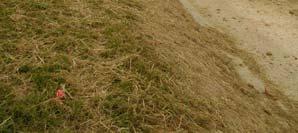
1 Massive Streambank Failure at New Outfall in a Suburban Area Module 5: Channel and Slope Stability Robert Pitt Department of Civil, Construction and Environmental Engineering University of Alabama Tuscaloosa, AL WI DNR photo Channel and Slope Protection Some potential solutions to stabilize streambanks. Upslope diversions Channel Protection Channel liners Check dams Slope Protection Roughening surface Erosion control mats
2 Slope Diversions Channel Lining

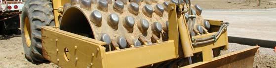
3 Check Dams Roughening Slopes while Compacting Ground


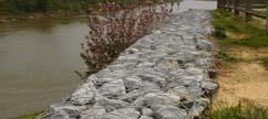
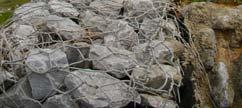
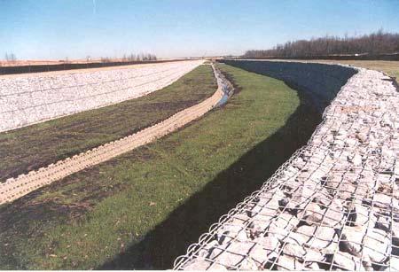
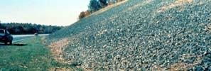
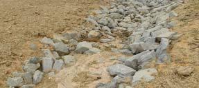
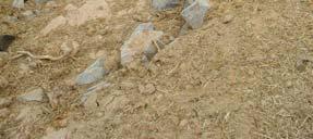
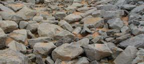
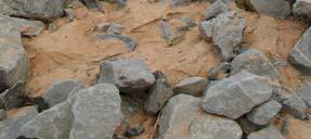
4 Gabions for Channel and Slope Protection Slope Protection Using Different Materials Coir Logs and Sprayed-on Mulch with Adhesive Rock and Asphalt for Shaded Areas

.")
5 Channel Design Based on Allowable Velocity and Shear Stress The concepts of allowable velocity and allowable shear stress are closely linked. Shear stress is calculated based on water depth and channel slope. Velocity is affected by both slope and depth. Most allowable velocity charts also include slope categories for the different liner materials. Some allowable velocity charts also consider silt content (water carrying silt has a higher allowable velocity because its sediment carrying capacity is already reduced). Liner Texture Example Allowable Velocity and Shear Stress Values Manning s roughness Clear Water (diversions) Silty Water (on site and downslope) o RS Boundary Shear Stress (tractive force): o RS n V (ft/sec) o (lb/ft ) V (ft/sec) o (lb/ft ) Fine sand Firm loam Fine gravel Cobbles γ = specific weight of water (6.4 lbs/ft 3 ) R = hydraulic radius (flow depth is used for maximum shear stress calculations; for sheetflow conditions, the depth is equal to the hydraulic radius) S = channel slope Chow 1959
(0.01 ft)(0.10) = 0.")


6 Example plot of allowable shear stress (unit tractive force) for cohesive materials. Chow 1959 COE 1994 Example Allowable Tractive Forces Sheetflow: ¼ inch deep on a 10 % slope: (6.4 lb/ft 3 )(0.01 ft)(0.10) = 0.13 lb/ft >3.5 mm particles OK, for high slit content flow >5 mm particles OK, for clear flow Moderately compacted cohesive clays OK Sheetflow: ¼ inch deep on a % slope: (6.4 lb/ft 3 )(0.01 ft)(0.0) = 0.06 lb/ft > 0.1 mm particles OK, for all flows OK for all loose and more compacted cohesive clays Example Allowable Tractive Forces (cont.) Channel Flow: 18 inches deep on a 5 % slope: (6.4 lb/ft 3 )(1.5 ft)(0.05) = 4.7 lb/ft no natural lining material safe Channel Flow: 18 inches deep on a 1 % slope: (6.4 lb/ft 3 )(1.5 ft)(0.01) = 0.93 lb/ft >70 mm noncohesive material OK
, the channel slope (S), and the maximum permissible velocity (V) for the channel.")
 3.")
: A P R Channel Design Steps for Maximum Permissible Velocity/Allowable Shear Stress Method (cont.) 5.")
7 Channel Design Steps for Maximum Permissible Velocity/Allowable Shear Stress Method 1. Estimate Manning s roughness (n), the channel slope (S), and the maximum permissible velocity (V) for the channel.. Calculate the hydraulic radius (R) using Manning s equation for these conditions. R 1.5 Vn S Channel Design Steps for Maximum Permissible Velocity/Allowable Shear Stress Method (cont.) 3. Calculate the required cross-sectional area (A) using the continuity equation and the design storm peak flow rate (Q): Q A V 4. Calculate the corresponding wetted perimeter (P): A P R Channel Design Steps for Maximum Permissible Velocity/Allowable Shear Stress Method (cont.) 5. Calculate an appropriate channel base width (b) and depth (y) corresponding to a specific channel geometry (usually a trapezoidal channel having a slide slope of z:1). 5b. Chow s nomograph can be used to significantly shorten the calculation effort by using the following form of Manning s equation: AR 3 nq 1.49S 0.5 Chow s (1959) nomograph to determine normal depth for different channel geometries and flows:
8 Example Design of Stable Channel Noncolloidal alluvial silts channel lining, water transporting colloidal silts: Manning s roughness (n) = 0.00 Maximum permissible velocity (V) = 3.5 ft/sec Allowable shear stress is 0.15 lb/ft The previously calculated peak discharge (Q) = 13 ft 3 /sec The channel slope (S) = 1%, or 0.01 The hydraulic radius (R) using Manning s equation: 1.5 Vn R.49S ft The required cross-sectional area: Q A V ft Therefore, AR /3 = (3.7)(0.3) /3 = 1.7 and the wetter perimeter = A/R = 3.7/0.3 = 1 ft There are many channel options available, Side slope z Channel options that meet allowable velocity criterion: Bottom width b AR /3 /b 8/3 y/b Normal depth y Max shear stress ft Safety factor for shear As the channel becomes wide, the side slope has little effect on the normal depth and therefore on the shear stress. Even though all these channels meet the permissible channel velocity, only those approaching 5 feet wide also meet the allowable shear stress. Since the allowable shear stress is 0.15 lb/ft, the normal depth must be less than 0.4 ft (about 3 inches), requiring a relatively wide channel. Current practice is to design channel liners based on shear stress and not on allowable velocity, as it does a better job in predicting liner stability.


9 Channel Design using Reinforced Liners If a channel will have intermittent flows, it is common to use vegetated liners to increase channel stability. If channel will have perennial flows, then structural liners must be used. Reinforced turf mat liner design should examine three phases: Original channel in unvegetated condition Channel in partially vegetated condition Channel in permanent condition with established vegetation Sod placed along a drainage bottom, with grass seed along the edges Seeding along median strip swale of highway project Temporary Vegetation Plantings barley (Hordeum vulgare L.), noted for its early fall growth; oats (Avena) sativa L.), in areas of mild winters; mixtures of wheat, oats, barley, and rye (Secale cereale L.); field bromegrass (Bromus spp.); and ryegrasses (Lolium spp.). Bermudagrass is most widely used permanent grass in the sourthern US (for permanent plantings)
10 Channel matting failure is based on soil loss (usually maximum of 0.5 inch; greater amounts hinder the establishment of vegetation. Basic shear stress formula can be modified to predict the shear stress applied to the soil beneath a channel mat: ns e DS1 C f n e = effective shear stress exerted on soil beneath vegetation γ = specific weight of water (6.4 lbs/ft 3 ) D = the maximum flow depth in the cross section (ft) S = hydraulic slope (ft/ft) C f = vegetal cover factor (this factor is 0 for an unlined channel) n s = roughness coefficient of underlying soil n = roughness coefficient of vegetal components Cover Factor (C f ) (good uniform stands) Covers Tested 0.90 bermudagrass centipedegrass buffalograss kentucky bluegrass blue grama grass mixture weeping lovegrass yellow bluestem alfalfa lespedeza sericea common lespedeza sudangrass 50 Reference stem density (M), stem/ft Allowable effective stress for noncohesive soils Soil grain roughness for noncohesive soils
 Indoor Channel Trendlines in Comparision to Stillwater Curves USDA Stillwater, OK, tests 1.00 0.90 Outdoor Swale Data 0.80 Manning's\"n\" 0.70 0.60 0.50 0.40 0.")
11 Standard VR-n curves for deep channel flows VR-n curve for different grasses, showing results for shallow flows; Univ. of Alabama tests (Kirby 003) Indoor Channel Trendlines in Comparision to Stillwater Curves USDA Stillwater, OK, tests Outdoor Swale Data 0.80 Manning's"n" Centipede Zoysia (multiply ft /sec by 0.09 to obtain m /sec) Retardance Classes ( A - E) A B C 0.0 Bluegrass D 0.10 E E E E E E+00 VR (m^/sec) Example Problem for the Selection of Roughness Coefficient for Grass-Lined Channels Determine the roughness value for a 10-year design storm of 70 ft 3 /sec ( m 3 /sec) in a grass-lined drainage channel having a slope of 0.05 ft/ft and a 4 foot (1. m) bottom width and 1:1 side slopes. The grass cover is expected to be in retardance group D. AR/3/b8/3 = 10.51/40.3 = 0.6 Long-term design, based on vegetated channel stability: use Q peak = Q 10year = 70 ft 3 /s ( m 3 /s) initially assume that n vegetated = 0.05 Determine the normal depth of flow: nq cfs 3 AR S AR /3 /b 8/3 = 10.51/40.3 = 0.6 With a 1:1 side slope trapezoidal channel, the ratio of y/b is 0.43, and the depth is 4(0.43) = 1.7 ft. The cross-sectional area = 9.7 ft The velocity = (70 ft 3 /sec)/(9.7 ft ) = 7. ft/sec P = 8.8 ft R = 9.7 ft /8.8 ft = 1.1 ft VR is therefore = (7. ft/sec)(1.1 ft) = 7.9 ft /sec From the VR-n curve, the new n is therefore 0.03 for retardance class D grass. The normal depth must be re-calculated: AR 3 nq 1.49S cfs
/(7.6 ft ) = 9. ft/sec P = 8.0 ft R = 7.6 ft /8.0 ft = 0.")
 is therefore: γds= (6.4 lb/ft 3 ) (1.4 ft) 0.05 ft/ft) = 4.")
 RUSLE Conservation Coefficients (C) Slope Gradients (S)")


12 AR /3 /b 8/3 = 6.7/40.3 = 0.17 With a 1:1 side slope trapezoidal channel, the ratio of y/b is 0.34, and the depth is 4(0.34) = 1.4 ft. The cross-sectional area = 7.6 ft The velocity = (70 ft 3 /sec)/(7.6 ft ) = 9. ft/sec P = 8.0 ft R = 7.6 ft /8.0 ft = 0.95 ft VR is therefore = (9. ft/sec)(0.95 ft) = 8.7 ft /sec From the VR-n curve, the revised value of n is still close to 0.03 The maximum shear stress (using normal depth instead of hydraulic radius) is therefore: γds= (6.4 lb/ft 3 ) (1.4 ft) 0.05 ft/ft) = 4.4 lb/ft This is a relatively large value for shear stress, requiring reinforcement. Example Specifications for Erosion Control Blanket (NAG S150BN Straw, 10 month life) RUSLE Conservation Coefficients (C) Slope Gradients (S) Channel Roughness Coefficients (n) Flow depth (ft) Manning s n (unvegetated) Slope length <3:1 3:1 to :1 <0.50 ft (ft) < 0 ft to ft to to > ft 0.01 >50 ft Max. permissible shear stress: 1.85 lb/ft Example for Matted Channel Liner Consider the following example: Calculated max. shear stress:.83 lb/ft, requiring a NAG P300 permanent mat. n s for the soil is n for the vegetated mat is 0.04 C f for the vegetated mat is 0.87 The permissible shear stress for the underlying soil is 0.08 lb/ft e The safety factor is therefore 0.08/0.053 = 1.5 and the channel lining system is expected to be stable.
![Example of a permanent channel design, with a liner: n = 0.0 Q = 9 CFS S = 8% (0.08) One possible solution: AR 3 0.0 9 0.08 1.49 0.5 1.38 A = [(7.64+5)/] (0.44) =.78 ft V = Q/A = 9 ft 3 /sec/.](/docs-images/75/72356060/images/13-2.jpg "78 ft = 10.4 ft/sec R = A/P P = 5 + (3.16)(0.44) = 7.78 ft. R = A/P =.78 ft/7.78 ft. = 0.36 ft. τ = γrs = (6.4lb/ft 3 )(0.36 ft.)(0.08) = 1.")
![8 lb/ft which is relatively large (The permissible shear stress for the underlying soil is 0.08 lb/ft ) Another alternative design with a liner: A = [(5+9.)/] (0.7) = 4.97 ft P = 5 + (1.1) = 7.](/docs-images/75/72356060/images/13-3.jpg "4 ft R = A/P = 4.97/7.4 = 0.67 τ = γds = (6.4lb/ft 3 )(0.70 ft.)(0.08) = 3.49 lb/ft (design case using normal depth) V = Q/A = 9 ft 3 /sec/4.97 ft = 5.")
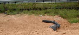
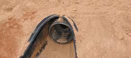
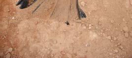
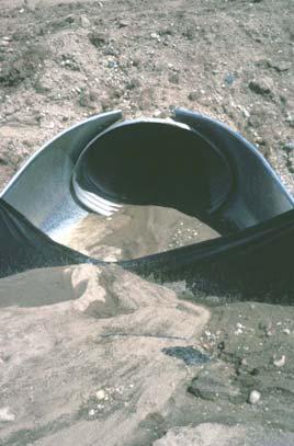
13 Example of a permanent channel design, with a liner: n = 0.0 Q = 9 CFS S = 8% (0.08) One possible solution: AR A = [(7.64+5)/] (0.44) =.78 ft V = Q/A = 9 ft 3 /sec/.78 ft = 10.4 ft/sec R = A/P P = 5 + (3.16)(0.44) = 7.78 ft. R = A/P =.78 ft/7.78 ft. = 0.36 ft. τ = γrs = (6.4lb/ft 3 )(0.36 ft.)(0.08) = 1.8 lb/ft which is relatively large (The permissible shear stress for the underlying soil is 0.08 lb/ft ) Another alternative design with a liner: A = [(5+9.)/] (0.7) = 4.97 ft P = 5 + (1.1) = 7.4 ft R = A/P = 4.97/7.4 = 0.67 τ = γds = (6.4lb/ft 3 )(0.70 ft.)(0.08) = 3.49 lb/ft (design case using normal depth) V = Q/A = 9 ft 3 /sec/4.97 ft = 5.8 ft/sec Permanent C350 liner, 5 ft bottom width, z=3 side slope, and phase 3 vegetation plant stage (mature) n s = 0.016; C f = 0.87 phase 3 Effective shear stress on underlying soil: ns C 3.49lb / ft lb / ft e DS f n The permissible shear stress for the underlying soil is 0.08 lb/ft Channel Design using Concrete and Riprap Liner Materials A lined swale is a constructed channel with a permanent lining designed to carry concentrated runoff to a stable outlet. This practice applies where grass swales are unsuitable because of conditions such as steep channel grades, prolonged flow areas, soils that are too erodible or not suitable to support vegetation or insufficient space is available AL Handbook Even concrete-lined channels and pipes may fail Capacity graph for concrete flumes, depth of flow = 0.50 feet WI DNR photo Alabama Handbook


![Chutes by Robinson, Rice, and Kadavy. For swale slopes between % and 10%: d 50 = [q (S) 1.5 /4.75x10-3 ] 1/1.89 For swale slopes between 10% and 40%: d 50 = [q (S) 0.58 /3.93x10 - ] 1/1.](/docs-images/75/72356060/images/14-2.jpg "89 d 50 = Particle size for which 50 % of the sample is finer, inch S = Bed slope, ft/ft q = Unit discharge, ft 3 /s/ft (Total discharge/bottom width) Size of Riprap Stones Weight (lbs) Mean")
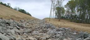
14 A riprap-lined swale is a natural or constructed channel with an erosion-resistant rock lining designed to carry concentrated runoff to a stable outlet. This practice applies where grass swales are unsuitable because of conditions such as steep channel grades, prolonged flow areas, soils that are too erodible or not suitable to support vegetation or insufficient space. Alabama Handbook Riprap-lined Swale Stable rock sizes, for rock lined swales having gradients between percent and 40 percent should be determined using the following formulas from Design of Rock Chutes by Robinson, Rice, and Kadavy. For swale slopes between % and 10%: d 50 = [q (S) 1.5 /4.75x10-3 ] 1/1.89 For swale slopes between 10% and 40%: d 50 = [q (S) 0.58 /3.93x10 - ] 1/1.89 d 50 = Particle size for which 50 % of the sample is finer, inch S = Bed slope, ft/ft q = Unit discharge, ft 3 /s/ft (Total discharge/bottom width) Size of Riprap Stones Weight (lbs) Mean Spherical Diameter (feet) Rectangular Shape Length Width, Height (feet) Graded Riprap Class Weight (lbs.) d 10 d 15 d 5 d 50 d 75 d


 D = Average rock diameter in the check dam (ft) Q h = 3 ft L = 3 ft L / D h / 3 W.5 L W = 15 ft, D = 9 inches = 0.75 ft 0.")

15 Check dams are small barriers or dams constructed across a swale, drainage ditch or areas of concentrated flow. Check dams are to prevent or reduce erosion by lessening the gradient of the flow channel which reduces the velocity of storm water flows. Some sediment will be trapped upstream from the check dams, but its volume will be insignificant and should not be considered in off-site sediment reduction. Alabama Handbook Check Dams Flow Rates through Stone Check Dams Q h / 3 W L / D.5 L 0. 5 Q = Outflow through the stone check dam (cfs) h = Ponding depth behind the check dam (ft) W = Width of the check dam (ft), not to be confused with the horizontal flow path length through the check dam L = Horizontal flow path length through the check dam (ft) D = Average rock diameter in the check dam (ft) Q h = 3 ft L = 3 ft L / D h / 3 W.5 L W = 15 ft, D = 9 inches = 0.75 ft ft / 15 ft 3 ft / 0.75 ft.5 3 ft ft 3 / sec Example Design for Reinforced Grass-Lined Channels with Check Dams and Level Spreader Pads A new industrial site in Huntsville, AL, has several -acre individual building sites. Each of the sites will be served with a grass-lined channel that will carry site water to a larger swale system. The slopes of the channels vary from about 1 to 6.5%. The calculated peak flow from each construction site was calculated to be 16 ft 3 /sec (corresponding to the Huntsville, AL, 5 yr design storm of 6.3 inches for 4 hours). A grass-lined channel is to be designed for each site. The bare seed bed is assumed to have a hydraulic roughness of about


 Safety factor (allowable shear stress")


16 The seed bed has an allowable shear stress of about 0.05 lb/ft. The calculated values for unprotected conditions are all much larger. Therefore, a North American Green S75 mat was selected, having an allowable shear stress of 1.55 lb/ft and a life of 1 months. Slope Bare seed bed shear stress (lb/ft ) Unvegetated mat shear stress, effect on soil (lb/ft ) Safety factor (allowable shear stress of 0.05 lb/ft ) 1% % % % Maximum velocity with mature vegetation (ft/sec) The check dams are assumed to be ft high to the maximum over-topping elevation in 3 ft deep channels. In channels with 5% slopes, the check dams would have to be about 40 ft apart (or less) to ensure that the toes of the upstream check dams were at the same, or lower, elevations as the overflows of the downstream dams. Similarly, the check dams in the 6.5% sloped channels would have to be no more than 30 ft apart. Slope Stability

 n is the sheet flow roughness coefficient for the slope surface, and s is the slope (as a fraction) The basic shear stress equation can be used to calculate the")
 = 00 ft Therefore the unit width peak flow = Q/W =. ft 3 /sec/00 ft = 0.11 ft /sec Slope roughness (n) = 0.")

 The corresponding maximum shear stress would therefore be: lb/ft For an ordinary firm loam soil, the Manning s roughness is 0.")
17 Slope Stability Applied to Erosion Control The basic shear stress calculations can be applied to slopes, using the flow depth of the sheetflow Sheetflow flow depth can be calculated using the Manning s equation: 3 5 qn y s y is the flow depth (in feet), q is the unit width flow rate (Q/W, the total flow rate, in ft 3 /sec, divided by the slope width, in ft.) n is the sheet flow roughness coefficient for the slope surface, and s is the slope (as a fraction) The basic shear stress equation can be used to calculate the maximum shear stress expected on a slope: o ys Slope Stability Example Design storm peak flow rate (Q) =. ft 3 /sec Slope width (W) = 00 ft Therefore the unit width peak flow = Q/W =. ft 3 /sec/00 ft = 0.11 ft /sec Slope roughness (n) = 0.4 (vegetated with dense grass; would be only about for an erosion control mat before vegetation establishment, using the established vegetation condition results in deeper water and therefore a worst case shear stress condition). y ft 0.5 o (about 0.4 inches) The corresponding maximum shear stress would therefore be: lb/ft For an ordinary firm loam soil, the Manning s roughness is 0.00 and the allowable shear stress is 0.15 lb/ft. Without a protective mat, the calculated maximum shear stress is substantially greater than the allowable shear stress for the soil. The effective shear stress underneath the mat would be: ns e 1 C 0.00 o f lb/ft n The safety factor would be about 1.5/0.067 =. Any mat with a Manning s n greater than about would be adequate for this example.
: Soil loss = (350)(0.8)(10.")
 The unprotected bare slope would lose about 6.3 inches of soil per year, while the protected slope would lose about 1. inches per year. The USDA uses a maximum loss rate of 0.")


18 Checking Erosion Yield of Protected Slope The final erosion control mat selection must be based on the expected erosion rate for the protected slope. R = 350 (Birmingham, AL conditions) K = 0.8 LS for slope length of 300 ft and slope of 5% = ft by 300 ft slope would have an area of 1.4 acres For a bare slope (C = 1): Soil loss = (350)(0.8)(10.81)(1) = 1060 tons/acre/yr For a protected slope (C = 0.19, and n = for a NAG S75 mat): Soil loss = (350)(0.8)(10.81)(0.19) = 01 tons/acre/yr Checking Erosion Yield of Protected Slope (cont.) The unprotected bare slope would lose about 6.3 inches of soil per year, while the protected slope would lose about 1. inches per year. The USDA uses a maximum loss rate of 0.5 inches per year to allowable plants to survive. Others have proposed a limit of 0.5 inches per year. This is about 4 tons/acre/year (still about 10X the typical USDA limit for agricultural operations). The maximum C value for this slope would therefore be about 0.039, requiring the selection of a more substantial erosion control mat. The minimum roughness n for this slope is 0.037, based on the previous shear stress calculations. North American Green Conservation Factors for Different Erosion Control Mats, for Different Slopes and Slope Lengths Slope length and gradient S75 S150 SC150 C15 S75BN S150BN CS150BN C15BN C350 P300 Length between 0 and 50 ft (6 to 15 m) S 3: S between 3: to :1 S : Length 50 ft (15 m) S 3: S between 3: to :1 S :

19 Treatment RUSLE Cover Factors (C) for Grasses Mulch rate (tons/acre) Slope (%) <6 weeks 1.5 to 6 months 6-1 months No mulching or -- all seeding Seeded grass none all < < < Organic and synthetic blankets and composite mats -- all Synthetic mats -- all = (6.4 lb/ft )(0.0 ft)(0.15) = 0.18 lb/ft qn y 1.49s o ys Example Slope Stability Calculation The total critical flow rate off this hillside was previously calculated to be 1. ft 3 /sec. The Manning s n of the soil (n s ) is ( 0.01)(0.05) 5 y 0.0 ft 0. 1in (0.15) = (6.4 lb/ft )(0.0 ft)(0.15) = 0.18 lb/ft 3 The allowable shear stress for the soils on this hillside is only 0.11 lb/ft, and a vegetated mat will therefore be needed. The mat needs to have an n of at least: ft n lb / Solving for n = Using RUSLE: R = 350/yr k = 0.8 LS =.5 (for 104 ft slope at 15%) R = (350)(0.8)(.5) = 45 tons/acre/year This corresponds to 45 ( ) = 1.45 inches per year. With a maximum allowable erosion loss of 0.5 inches per year, the C factor for the mat must be: 0.5/1.45 = 0.17 Many mats that have this C factor for this slope condition (all except S75). In this example, the selection of a mat having an n of 0.067, or greater will be difficult. Most mats are in the range of 0.0 to It will therefore be necessary to use filter fences, coir logs, or other methods to provide additional flow resistance to the flow on this slope. Alternatively, the slope length can be shortened with a bench and diversion.
 is the most common chemical being sold now. Polyacrylamide used for erosion control should have a negative (anionic) molecular charge.")
 Design an appropriate diversion swale, or a main drainage swale for your evaluation site.")
20 Chemical Treatment of Exposed Soils These newly developed materials act by chemically combining small soil particles into larger discrete particles that are more effective in settling in ponds and in channels. Polyacrylamide (PAM) is the most common chemical being sold now. Polyacrylamide used for erosion control should have a negative (anionic) molecular charge. Homework for Chapter 5 1) Identify several different slope categories on your construction evaluation site and propose suitable control practices for each type. Justify your selections with appropriate calculations. ) Design an appropriate diversion swale, or a main drainage swale for your evaluation site. Using the previously calculated flow rates, select a suitable channel lining, including the consideration of check dams. Justify your selections with appropriate calculations.
Module 5: Channel and Slope Protection Example Assignments
 Module 5: Channel and Slope Protection Example Assignments A) Example Project Assignment on Slope and Swale Design North America Green Software Example (Erosion Control Materials Design Software) The following
APPENDIX B DESIGN CRITERIA FOR TEMPORARY WATER QUALITY BMPS USED DURING CONSTRUCTION
 APPENDIX B DESIGN CRITERIA FOR TEMPORARY WATER QUALITY BMPS USED DURING CONSTRUCTION This Appendix presents design criteria and example calculations for the following temporary water quality BMPs for use
Module 5: Channel and Slope Stability for Construction Site Erosion Control
 R. Pitt June 16, 2004 Module 5: Channel and Slope Stability for Construction Site Erosion Control Introduction...1 General Channel Stability Shear Stress Relationship...2 Allowable Velocity and Shear Stress...4
BACK. Stability design of a grass-lined stress requires the determination The first is the retardance curve potential of the vegetal cover to
 3. DETERMINATION OF CHANNEL DESIGN PARAMETERS By D.M. Temple BACK The conditions governing the stability of a grass-lined open channel are the channel geometry and slope, the erodibility of the soil boundary,
Selected Site BMPs: Why s the Water Muddy? John C. Hayes, Ph.D., P. E. Biosystems Engineering Clemson University
 Selected Site BMPs: Why s the Water Muddy? John C. Hayes, Ph.D., P. E. Biosystems Engineering Clemson University The BMP worked fine until last week when it rained! Turbidity Best Management Practices
5. ROADSIDE AND MEDIAN CHANNELS
 5. ROADSIDE AND MEDIAN CHANNELS Roadside and median channels are open-channel systems which collect and convey stormwater from the pavement surface, roadside, and median areas. These channels may outlet
Open Channel Flow Part 2. Ch 10 Young, notes, handouts
 Open Channel Flow Part 2 Ch 10 Young, notes, handouts Uniform Channel Flow Many situations have a good approximation d(v,y,q)/dx=0 Uniform flow Look at extended Bernoulli equation Friction slope exactly
APPENDIX B WORKSHEETS & EXHIBITS
 APPENDIX B WORKSHEETS & EXHIBITS A worksheet provides the designer a representation of a measure that allows for input of specific design criteria. The plan designer will be required to assess field conditions
What Is Water Erosion? Aren t they the same thing? What Is Sediment? What Is Sedimentation? How can Sediment Yields be Minimized?
 Jerald S. Fifield, Ph.D. CISEC HydroDynamics Incorporated Parker, CO 303-841-0377 Aren t they the same thing? What Is Sediment? Soil particles deposited or suspended in water or air The process of depositing
Sediment Trap. A temporary runoff containment area, which promotes sedimentation prior to discharge of the runoff through a stabilized spillway.
 Sediment Trap SC-15 Source: Caltrans Construction Site Best Management Practices Manual, 2003. Description A temporary runoff containment area, which promotes sedimentation prior to discharge of the runoff
**Temporary Erosion Control**
 Construction operations And methods **Temporary Erosion Control** The test will more than likely just have a basic word problem dealing with Erosion control, if it has anything on the test. So just review,
Stone Outlet Sediment Trap
 3.12 Sediment Control Description: A stone outlet sediment trap is a small detention area formed by placing a stone embankment with an integral stone filter outlet across a drainage swale for the purpose
APPENDIX F GUIDELINES FOR DESIGN OF OPEN CHANNELS
 GUIDELINES FOR DESIGN OF OPEN CHANNELS June 2011 THIS PAGE LEFT BLANK INTENTIONALLY. June 2011 FIGURES Figure F.1 Water Surface Profile of Channel with Uniform Flow Figure F.2 Manning s n for Class A Vegetation
Rock Sizing for Small Dam Spillways
 Rock Sizing for Small Dam Spillways STORMWATER MANAGEMENT PRACTICES Photo 1 Rock-lined spillway on a construction site sediment basin Photo 2 Rock-lined spillway on a small farm dam 1. Introduction A chute
TPDES: Soil, Erosion and Sedimentation Methods
 SAWS TPDES: Soil, Erosion and Sedimentation Methods Philip Handley Supervisor-Resource Protection & Compliance August 25, 2014 TPDES: Soil, Erosion and Sedimentation Methods Soil Common term: Dirt Common
Agenda. INDOT Office of Environmental Services. Describe Results of FHWA QAR. Landscape and Waterway Permitting Unit. Interviews Site Inspections
 Nathan Saxe Administrator, Ecology and Waterway Permitting Section Back to Basics: Erosion and Sediment Control FHWA INDOT Quality Assurance Review (QAR) Results 1 Agenda INDOT Office of Environmental
Materials. Use materials meeting the following.
 208.01 Section 208. SOIL EROSION AND SEDIMENTATION CONTROL 208.01 Description. Install and maintain erosion and sedimentation controls to minimize soil erosion and to control sedimentation from affecting
Sediment and Erosion Design Guide
 Sediment and Erosion Design Guide Sediment Transport & Bulking Factors Goals of this Session Review key principals Review basic relationships and available tools Review bulking factor relationships Purposes
B805 TEMPORARY EROSION AND SEDIMENT CONTROL MEASURES - OPSS 805
 B805 MEASURES - OPSS 805 805.1 GENERAL Construction activities frequently remove protective cover and expose soil to accelerated rates of erosion. Sediments generated thereby can be conveyed via runoff
Continuing Education Associated with Maintaining CPESC and CESSWI Certification
 Continuing Education Associated with Maintaining CPESC and CESSWI Certification Module 2: Stormwater Management Principles for Earth Disturbing Activities Sponsors: ODOTs Local Technical Assistance Program
Rock Sizing for Batter Chutes
 Rock Sizing for Batter Chutes STORMWATER MANAGEMENT PRACTICES Photo 1 Rock-lined batter chute Photo 2 Rock-lined batter chute 1. Introduction In the stormwater industry a chute is a steep drainage channel,
Rock Sizing for Waterway & Gully Chutes
 Rock Sizing for Waterway & Gully Chutes WATERWAY MANAGEMENT PRACTICES Photo 1 Rock-lined waterway chute Photo 2 Rock-lined gully chute 1. Introduction A waterway chute is a stabilised section of channel
CONCEPTS Conservational Channel Evolution and Pollutant Transport System
 CONCEPTS Conservational Channel Evolution and Pollutant Transport System Eddy J. Langendoen Watershed Physical Processes Research Unit National Sedimentation Laboratory USDA Agricultural Research Service
Open Channel Flow I - The Manning Equation and Uniform Flow COURSE CONTENT
 Open Channel Flow I - The Manning Equation and Uniform Flow Harlan H. Bengtson, PhD, P.E. COURSE CONTENT 1. Introduction Flow of a liquid may take place either as open channel flow or pressure flow. Pressure
Erosion and Sedimentation Basics
 Erosion and Sedimentation Basics Coastal San Luis Resource Conservation District G.W. Bates, PE, CPESC Outline: 1. Terms & Concepts 2. Causes of Erosion 3. The Erosion/Sedimentation Process 4. Erosion
Evaluation of Miramat Under High Velocity Flows
 Utah State University DigitalCommons@USU Reports Utah Water Research Laboratory January 1985 Evaluation of Miramat Under High Velocity Flows C. Earl Israelsen Frank W. Haws Follow this and additional works
APPENDIX G APPENDIX G SEDIMENT CONTAINMENT SYSTEM DESIGN RATIONALE
 APPENDIX G SEDIMENT CONTAINMENT SYSTEM DESIGN RATIONALE March 18, 2003 This page left blank intentionally. March 18, 2003 G-2 FIGURES Page # Figure G.1 Estimated Runoff from Precipitation Over Different
Standards for Soil Erosion and Sediment Control in New Jersey May 2012
 STANDARD FOR SEDIMENT BASIN Definition A barrier, dam, excavated pit, or dugout constructed across a waterway or at other suitable locations to intercept and retain sediment. Basins created by construction
[1] Performance of the sediment trap depends on the type of outlet structure and the settling pond surface area.
![[1] Performance of the sediment trap depends on the type of outlet structure and the settling pond surface area.](/thumbs/76/74245181.jpg "[1] Performance of the sediment trap depends on the type of outlet structure and the settling pond surface area.") Sediment Trench SEDIMENT CONTROL TECHNIQUE Type 1 System Sheet Flow Sandy Soils Type 2 System [1] Concentrated Flow Clayey Soils Type 3 System [1] Supplementary Trap Dispersive Soils [1] Performance of
Sediment Trench SEDIMENT CONTROL TECHNIQUE Type 1 System Sheet Flow Sandy Soils Type 2 System [1] Concentrated Flow Clayey Soils Type 3 System [1] Supplementary Trap Dispersive Soils [1] Performance of
Advanced Hydraulics Prof. Dr. Suresh A Kartha Department of Civil Engineering Indian Institute of Technology, Guwahati
 Advanced Hydraulics Prof. Dr. Suresh A Kartha Department of Civil Engineering Indian Institute of Technology, Guwahati Module - 2 Uniform Flows Lecture - 6 Design of Channels for Uniform Flow (Refer Slide
Shear Stress Estimates for Combined Wave and Surge Overtopping at Earthen Levees
 Shear Stress Estimates for Combined Wave and Surge Overtopping at Earthen Levees by Norberto C. Nadal and Steven A. Hughes PURPOSE: The Coastal and Hydraulics Engineering Technical Note (CHETN) described
INFLOW DESIGN FLOOD CONTROL SYSTEM PLAN 40 C.F.R. PART PLANT YATES ASH POND 2 (AP-2) GEORGIA POWER COMPANY
 GEORGIA POWER COMPANY") INFLOW DESIGN FLOOD CONTROL SYSTEM PLAN 40 C.F.R. PART 257.82 PLANT YATES ASH POND 2 (AP-2) GEORGIA POWER COMPANY EPA s Disposal of Coal Combustion Residuals from Electric Utilities Final Rule (40 C.F.R.
INFLOW DESIGN FLOOD CONTROL SYSTEM PLAN 40 C.F.R. PART 257.82 PLANT YATES ASH POND 2 (AP-2) GEORGIA POWER COMPANY EPA s Disposal of Coal Combustion Residuals from Electric Utilities Final Rule (40 C.F.R.
Drivable Grass Report for Hydraulic Performance Testing
 Drivable Grass Report for Hydraulic Performance Testing Prepared for Soil Retention Products, Inc. Prepared by Michael D. Turner Amanda L. Cox Christopher I. Thornton March 2011 Colorado State University
Technical Memorandum. To: From: Copies: Date: 10/19/2017. Subject: Project No.: Greg Laird, Courtney Moore. Kevin Pilgrim and Travis Stroth
 Technical Memorandum To: From: Greg Laird, Courtney Moore Kevin Pilgrim and Travis Stroth 5777 Central Avenue Suite 228 Boulder, CO 80301 www.otak.com Copies: [Electronic submittal] Date: 10/19/2017 Subject:
Notes: Space for as many as two segments per flow type can be used for each worksheet. Include a map, schematic, or description of flow segments.
 Worksheet 3: Time of Concentration (Tc) or travel time (Tt) Project By Date Location Checked Date Check one: Present Developed Check one: Tc Tt through subarea Notes: Space for as many as two segments
Stormwater Outlet Sediment Traps
 Stormwater Outlet Traps SEDIMENT CONTROL TECHNIQUES Photo 1 Excavated sediment trap just prior to scheduled clean-out (note energy dissipater at end of pipe) Photo 2 A supplementary straw bale barrier
Vegetation effects on river hydraulics. Johannes J. (Joe) DeVries David Ford Consulting Engineers, Inc. Sacramento, CA
 DeVries David Ford Consulting Engineers, Inc. Sacramento, CA") Vegetation effects on river hydraulics Johannes J. (Joe) DeVries David Ford Consulting Engineers, Inc. Sacramento, CA jjdevries@ford-consulting.com SAC05 D2P31 RM 99.0L VIEW UPSTREAM AT UPSTREAM END DWR
Vegetation effects on river hydraulics Johannes J. (Joe) DeVries David Ford Consulting Engineers, Inc. Sacramento, CA jjdevries@ford-consulting.com SAC05 D2P31 RM 99.0L VIEW UPSTREAM AT UPSTREAM END DWR
Chapter Introduction EROSION AND SEDIMENT CONTROL. Erosion
 Chapter 8. EROSION AND SEDIMENT CONTROL 8.1. Introduction Natural erosion has been occurring since the earth was formed. This process, which generally occurs at a relatively slow rate, has shaped and molded
ONE ROCK DAM ORD. capture more sediment. The original ORD becomes the splash apron for the new layer. STEP 4: When ORD fills in, add a new layer
 ONE ROCK DAM ORD A low grade control structure built with a single layer of rock on the bed of the channel. ORDs stabilize the bed of the channel by slowing the flow of water, increasing roughness, recruiting
Module 4: Overview of the Fundamentals of Runoff and Erosion
 Module 4: Overview of the Fundamentals of Runoff and Erosion Module 4a Goal Once we can better understand the forces which cause erosion and runoff, only then can we begin to minimize the negative results.
OPEN CHANNEL FLOW. One-dimensional - neglect vertical and lateral variations in velocity. In other words, Q v = (1) A. Figure 1. One-dimensional Flow
 A. Figure 1. One-dimensional Flow") OPEN CHANNEL FLOW Page 1 OPEN CHANNEL FLOW Open Channel Flow (OCF) is flow with one boundary exposed to atmospheric pressure. The flow is not pressurized and occurs because of gravity. Flow Classification
OPEN CHANNEL FLOW Page 1 OPEN CHANNEL FLOW Open Channel Flow (OCF) is flow with one boundary exposed to atmospheric pressure. The flow is not pressurized and occurs because of gravity. Flow Classification
Coarse Sediment Traps
 Coarse Sediment Traps SEDIMENT CONTROL TECHNIQUE Type 1 System Sheet Flow Sandy Soils Type 2 System [1] Concentrated Flow Clayey Soils [2] Type 3 System Supplementary Trap Dispersive Soils [1] Though primarily
U-Shaped Sediment Traps
 U-Shaped Sediment Traps SEDIMENT CONTROL TECHNIQUE Type 1 System Sheet Flow Sandy Soils Type 2 System Concentrated Flow Clayey Soils [1] Type 3 System Supplementary Trap Dispersive Soils [1] Generally
STREUVER FIDELCO CAPPELLI, LLC YONKERS DOWNTOWN DEVELOPMENT PHASE 1. DRAFT ENVIRONMENTAL IMPACT STATEMENT For: PALISADES POINT
 STREUVER FIDELCO CAPPELLI, LLC YONKERS DOWNTOWN DEVELOPMENT PHASE 1 DRAFT ENVIRONMENTAL IMPACT STATEMENT For: PALISADES POINT Prepared by: PAULUS, SOKOLOWSKI & SARTOR STORMWATER MANAGEMENT 1. Methodology
Pressure Head: Pressure head is the height of a column of water that would exert a unit pressure equal to the pressure of the water.
 Design Manual Chapter - Stormwater D - Storm Sewer Design D- Storm Sewer Sizing A. Introduction The purpose of this section is to outline the basic hydraulic principles in order to determine the storm
Summary of Hydraulic and Sediment-transport. Analysis of Residual Sediment: Alternatives for the San Clemente Dam Removal/Retrofit Project,
 Appendix N SUMMARY OF HYDRAULIC AND SEDIMENT-TRANSPORT ANALYSIS OF RESIDUAL SEDIMENT: ALTERNATIVES FOR THE SAN CLEMENTE DAM REMOVAL/RETROFIT PROJECT, CALIFORNIA the San Clemente Dam Removal/Retrofit Project,
Design of RC Retaining Walls
 Lecture - 09 Design of RC Retaining Walls By: Prof Dr. Qaisar Ali Civil Engineering Department UET Peshawar www.drqaisarali.com 1 Topics Retaining Walls Terms Related to Retaining Walls Types of Retaining
Spreadsheet Tools for Quantifying the Costs and Benefits of Two-Stage Channels
 Spreadsheet Tools for Quantifying the Costs and Benefits of Two-Stage Channels J. Witter, A. Ward, D. Mecklenburg, J. D Ambrosio, S. Roley, and J. Tank AWRA Agricultural Hydrology and Water Quality II
Sediment Control Log (SCL)
") Description A sediment control log is a linear roll made of natural materials such as straw, coconut fiber, or other fibrous material trenched into the ground and held with a wooden stake. Sediment control
Description A sediment control log is a linear roll made of natural materials such as straw, coconut fiber, or other fibrous material trenched into the ground and held with a wooden stake. Sediment control
WQ Outlet Design Single Orifice Orifice diameter = 24. Perforated riser/orifice Plate Outlet area per perforation row = 4
 These calculations should be used when designing the outlet structures for extended wet and dry detention basins (Sections 4. 7 and 4.8). The water quality outlet size and the trash rack design will vary
Vetiver System for Stream Bank Stabilisation. Paul Truong
 Vetiver System for Stream Bank Stabilisation (With special references to the river and canal bank stabilisation in Australia and Vietnam) Paul Truong Director, The Vetiver Network International, Veticon
Stable Channel Analysis and Design
 PDHonline Course H145 (4 PDH) Stable Channel Analysis and Design Instructor: Joseph V. Bellini, PE, PH, DWRE, CFM 2012 PDH Online PDH Center 5272 Meadow Estates Drive Fairfax, VA 22030-6658 Phone & Fax:
Module 16: Sediment Transport in Storm Drainage Systems
 Module 16: Sediment Transport in Storm Drainage Systems R. Pitt March 25, 2004 Abstract...1 Background...2 Effects of Catchbasin and Street Cleaning...2 Particle Size Distributions...3 Settling of Particulates
Limitation to qualitative stability indicators. the real world is a continuum, not a dichotomy ~ 100 % 30 % ~ 100 % ~ 40 %
 Stream Stability Assessment & BEHI Surveys Joe Rathbun MDEQ Water Resources Division rathbunj@michigan.gov 517--373 517 373--8868 Stability Stream can transport its water and sediment inputs without changing
Culvert and Pipe Phasing
 Culvert and Pipe Phasing Barney Blackburn, PE, CPESC, CPSWQ NCDOT Roadside Environmental Unit Soil & Water Engineering Section Supervisor NCDOT Culvert Phasing Process Hydraulics Unit: Culvert Survey Report
Low Gradient Velocity Control Short Term Steep Gradient Channel Lining Medium-Long Term Outlet Control Soil Treatment Permanent [1]
![Low Gradient Velocity Control Short Term Steep Gradient Channel Lining Medium-Long Term Outlet Control Soil Treatment Permanent [1]](/thumbs/87/96478185.jpg "Low Gradient Velocity Control Short Term Steep Gradient Channel Lining Medium-Long Term Outlet Control Soil Treatment Permanent [1]") Rock Linings DRAINAGE CONTROL TECHNIQUE Low Gradient Velocity Control Short Term Steep Gradient Channel Lining Medium-Long Term Outlet Control Soil Treatment Permanent [1] [1] The design of permanent installations
Rock Linings DRAINAGE CONTROL TECHNIQUE Low Gradient Velocity Control Short Term Steep Gradient Channel Lining Medium-Long Term Outlet Control Soil Treatment Permanent [1] [1] The design of permanent installations
GEOSYNTHETICS ENGINEERING: IN THEORY AND PRACTICE
 GEOSYNTHETICS ENGINEERING: IN THEORY AND PRACTICE Prof. J. N. Mandal Department of civil engineering, IIT Bombay, Powai, Mumbai 400076, India. Tel.022-25767328 email: cejnm@civil.iitb.ac.in Module - 4
STRUCTURAL STABILITY ASSESSMENT
 STRUCTURAL STABILITY ASSESSMENT CFR 257.73(d) Bottom Ash Pond Complex Cardinal Plant Brilliant, Ohio October, 2016 Prepared for: Cardinal Operating Company Cardinal Plant Brilliant, Ohio Prepared by: Geotechnical
 DRAFT DRAFT DRAFT DRAFT DRAFT SEDIMENT CONTROLS Method Application Description BMP Sediment fencing Flat Ground Y Anywhere low flow runoff is Sloping Ground Y Geotextile fabric, buried at the bottom
Chutes Part 5: Rock linings
 Chutes Part 5: Rock linings DRAINAGE CONTROL TECHNIQUE Low Gradient Velocity Control Short-Term Steep Gradient Channel Lining Medium-Long Term Outlet Control [1] Soil Treatment Permanent [2] [1] Chutes
How & Where does infiltration work? Summary of Geologic History Constraints/benefits for different geologic units
 June 26, 2007: Low Impact Development 1 Associated Earth Sciences, Inc. Associated Earth Sciences, Inc. Presented by: Matthew A. Miller, PE April 24, 2012 How & Where does infiltration work? Summary of
Instream Erosion Control General
 Instream Erosion Control General EROSION CONTROL TECHNIQUES Revegetation Temperate Climates Short-Term Non Vegetation Wet Tropics Long-Term Weed Control [1] Semi-Arid Zones Permanent [1] Weed control attributes
Stormwater Inlet Sediment Traps
 Stormwater Inlet Sediment Traps SEDIMENT CONTROL TECHNIQUES Photo 1 Kerb inlet Photo 2 Field (drop) inlet Table 1 provides the recommended default classification of various sediment control systems suitable
Aquifer an underground zone or layer of sand, gravel, or porous rock that is saturated with water.
 Aggradation raising of the streambed by deposition that occurs when the energy of the water flowing through a stream reach is insufficient to transport sediment conveyed from upstream. Alluvium a general
Type 1 System Sheet Flow Sandy Soils Type 2 System Concentrated Flow Clayey Soils Type 3 System [1] Supplementary Trap Dispersive Soils
![Type 1 System Sheet Flow Sandy Soils Type 2 System Concentrated Flow Clayey Soils Type 3 System [1] Supplementary Trap Dispersive Soils](/thumbs/77/76519623.jpg "Type 1 System Sheet Flow Sandy Soils Type 2 System Concentrated Flow Clayey Soils Type 3 System [1] Supplementary Trap Dispersive Soils") Sediment Weirs SEDIMENT CONTROL TECHNIQUE Type 1 System Sheet Flow Sandy Soils Type 2 System Concentrated Flow Clayey Soils Type 3 System [1] Supplementary Trap Dispersive Soils [1] Type 3 classification
Sediment Weirs SEDIMENT CONTROL TECHNIQUE Type 1 System Sheet Flow Sandy Soils Type 2 System Concentrated Flow Clayey Soils Type 3 System [1] Supplementary Trap Dispersive Soils [1] Type 3 classification
Scattergraph Principles and Practice Evaluating Self-Cleansing in Existing Sewers Using the Tractive Force Method
 Scattergraph Principles and Practice Evaluating Self-Cleansing in Existing Sewers Using the Tractive Force Method Kevin L. Enfinger, P.E. and Paul S. Mitchell, P.E. ADS Environmental Services 4940 Research
December 11, 2006 File:
 December 11, 2006 File: 15-85-38 Alberta Infrastructure and Transportation Room 301, Provincial Building 9621-96 Avenue Peace River, Alberta T8S 1T4 Attention: Mr. Ed Szmata PEACE REGION (SWAN HILLS AREA)
Uniform Channel Flow Basic Concepts Hydromechanics VVR090
 Uniform Channel Flow Basic Concepts Hydromechanics VVR090 ppt by Magnus Larson; revised by Rolf L Feb 2014 SYNOPSIS 1. Definition of Uniform Flow 2. Momentum Equation for Uniform Flow 3. Resistance equations
Open Channel Hydraulics I - Uniform Flow
 PDHonline Course H138 (2 PDH) Open Channel Hydraulics I - Uniform Flow Instructor: Harlan H. Bengtson, Ph.D., PE 2012 PDH Online PDH Center 5272 Meadow Estates Drive Fairfax, VA 22030-6658 Phone & Fax:
Black Gore Creek 2013 Sediment Source Monitoring and TMDL Sediment Budget
 Black Gore Creek 2013 Sediment Source Monitoring and TMDL Sediment Budget Prepared for: Prepared By: - I. Introduction The Black Gore Creek Total Maximum Daily Load (TMDL) was developed in collaboration
Appendix F Channel Grade Control Structures
 Stream Simulation Appendix F Channel Grade Control Structures This appendix briefly describes permanent grade control structures that are sometimes needed in the upstream and/or downstream reaches adjacent
Erosion and Sediment Control Measures 2.7 Silt Fences
 Erosion and Sediment Control Measures Silt fences are designed to intercept sheet flow sediment laden stormwater run-off and filter out both the larger and smaller particles of sediment. Silt fences and
DEPARTMENT OF CIVIL AND ENVIRONMENTAL ENGINEERING Urban Drainage: Hydraulics. Solutions to problem sheet 2: Flows in open channels
 DEPRTMENT OF CIVIL ND ENVIRONMENTL ENGINEERING Urban Drainage: Hydraulics Solutions to problem sheet 2: Flows in open channels 1. rectangular channel of 1 m width carries water at a rate 0.1 m 3 /s. Plot
Sediment Trap. At multiple locations within the project site where sediment control is needed.
 Sediment Trap SE-3 Objectives EC Erosion Control SE Sediment Control TR Tracking Control WE Wind Erosion Control Non-Stormwater NS Management Control Waste Management and WM Materials Pollution Control
CONSTRUCTION EXIT SEDIMENT BARRIER
 241428_itizen ield Guide_v3 2/22/06 11:09 M Page 1 (1,1) ONSTRUTION EXIT stone pad located where traffic leaves a construction site to eliminate the transport of soil to public streets. SEDIMENT BRRIER
Continuing Education Course #101 Drainage Design with WinTR-55
 1 of 5 Continuing Education Course #101 Drainage Design with WinTR-55 1. WinTR-55 uses the Kinematic Wave method for calculating storm runoff rates and volumes. 2. According to the Velocity Method, the
CASE STUDIES. Introduction
 Introduction The City of Winston-Salem faces the challenge of maintaining public infrastructure (e.g., water and sewer lines, storm drains, roads, culverts and bridges) while minimizing the potential impacts
Contract Research. GDOT PROJ NO Final Report CATEGORIZATION OF EROSION CONTROL MATTING
 Contract Research GDOT PROJ NO. 07-25 Final Report CATEGORIZATION OF EROSION CONTROL MATTING Susan E. Burns, Ph.D, P.E. Professor School of Civil and Environmental Engineering Georgia Institute of Technology
Geomorphology Geology 450/750 Spring Fluvial Processes Project Analysis of Redwood Creek Field Data Due Wednesday, May 26
 Geomorphology Geology 450/750 Spring 2004 Fluvial Processes Project Analysis of Redwood Creek Field Data Due Wednesday, May 26 This exercise is intended to give you experience using field data you collected
A-JACKS CONCRETE ARMOR UNITS Channel Lining and Pier Scour Design Manual
 A-JACKS CONCRETE ARMOR UNITS Channel Lining and Pier Scour Design Manual Prepared for Armortec, Inc. Bowling Green, Kentucky P.O. Box 270460 Fort Collins, Colorado 80527 (970) 223-5556, FAX (970) 223-5578
ARMORED DITCH DEGRADATION AND ISSUES WITH EROSION
 ARMORED DITCH DEGRADATION AND ISSUES WITH EROSION Cody Morris, Department of Earth Sciences, University of South Alabama, Mobile AL, 36688. E- mail: csm805@jagmail.southalabama.edu. When armored ditches
Sediment Control Practices. John Mathews Ohio Dept. of Natural Resources, Division of Soil and Water Resources
 Sediment Control Practices John Mathews Ohio Dept. of Natural Resources, Division of Soil and Water Resources Practices Treat the Largest Soil Particles Sand Sand Silt Clay Treated Untreated Settleable
Gully Erosion Part 1 GULLY EROSION AND ITS CAUSES. Introduction. The mechanics of gully erosion
 Gully Erosion Part 1 GULLY EROSION AND ITS CAUSES Gully erosion A complex of processes whereby the removal of soil is characterised by incised channels in the landscape. NSW Soil Conservation Service,
APPENDIX A: EROSION & SEDIMENT CONTROL FORMS
 APPENDIX A: EROSION & SEDIMENT CONTROL FORMS Croy Engineering # 1580.08 EROSION & SEDIMENT CONTROL FORMS Appendix-1 This page intentionally left blank. Croy Engineering # 1580.08 EROSION & SEDIMENT CONTROL
Hydraulics Part: Open Channel Flow
 Hydraulics Part: Open Channel Flow Tutorial solutions -by Dr. K.N. Dulal Uniform flow 1. Show that discharge through a channel with steady flow is given by where A 1 and A 2 are the sectional areas of
~ W 89 CONTENTS J-1 J-1 J-6 J-7 J-9 J-10 J-10 J-10
 15 W 89 J-1. J-2. J-3. J-4. J-5. J-6 J-7. J-8. CONTENTS Introduction... Stable Slope Method... Example 1... Armor Bed Method... Example 2...*.... Dominant Discharge... Bed Material Gradation... Numerical
Long Valley Meadow Restoration Project
 Long Valley Meadow Restoration Project USDA Forest Service Mogollon Rim Ranger District Coconino National Forest Coconino County, Arizona T13N, R9E, Section 12 and T13N, R10E, Sections 6 and 7 Gila and
EROSION AND SEDIMENT CONTROL AT CONSTRUCTION SITES GUIDELINES. City of Moncton Engineering and Environmental Services
 EROSION AND SEDIMENT CONTROL AT CONSTRUCTION SITES GUIDELINES City of Moncton Engineering and Environmental Services Revised March 2011 TABLE OF CONTENTS INTRODUCTION... 2 THE EROSION AND SEDIMENT CONTROL
Instream Sediment Control Systems
 Instream Sediment Control Systems INSTREAM PRACTICES Photo 1 Photo 2 Modular sediment The information contained within this series of fact sheets deals only with the design of temporary instream sediment
In-class Exercise. Problem: Select load factors for the Strength I and Service I Limit States for the. Loading Diagram for Student Exercise
 In-class Exercise Problem: Select load factors for the Strength I and Service I Limit States for the problem illustrated below. Loading Diagram for Student Exercise For this exercise, complete the following
EROSION CONTROL NARRATIVE
 EROSION CONTROL NARRATIVE Erosion and sediment control has been designed for the Willow Bend Phase I Subdivision according to UDFCD and the City of Thornton criteria, in order to minimize erosion and sediment
CCR Rule Annual Inspection Report (cont.) 2
 2") The inspection findings consisted of maintenance items and items that were not observed to be signs or potential signs of significant structural weakness. No deficiencies or disrupting conditions that
The inspection findings consisted of maintenance items and items that were not observed to be signs or potential signs of significant structural weakness. No deficiencies or disrupting conditions that
STABILIZATION OF THE H&CT RAILWAY STONE DAM WALTER E. SKIPWITH, PE, JOYCE CRUM, AIA AND JOHN BAUMGARTNER, PE. Introduction.
 STABILIZATION OF THE H&CT RAILWAY STONE DAM WALTER E. SKIPWITH, PE, JOYCE CRUM, AIA AND JOHN BAUMGARTNER, PE I. A. Introduction General The Old Stone Dam is located in the upper reach of Cottonwood Creek
Experimental Study of the Sediment Trap Effect of Steel Grid-Type Sabo Dams
 Experimental Study of the Sediment Trap Effect of Steel Grid-Type Sabo Dams Teruyoshi TAKAHARA 1 and Kazuki MATSUMURA 1 1 Graduate school of Agriculture, Kyoto Pref. University (1-5 Shimogamonakaragicyo,
Large-Scale Sediment Retention Device Testing (ASTM D 7351) SedCatch Sediment Basket Inlet Filter Exposed to 6% Sediment Load
 SedCatch Sediment Basket Inlet Filter Exposed to 6% Sediment Load") Large-Scale Sediment Retention Device Testing (ASTM D 7351) of SedCatch Sediment Basket Inlet Filter Exposed to 6% Sediment Load February 2010 Submitted to: SedCatch Environmental Products 8380 Point O
Large-Scale Sediment Retention Device Testing (ASTM D 7351) of SedCatch Sediment Basket Inlet Filter Exposed to 6% Sediment Load February 2010 Submitted to: SedCatch Environmental Products 8380 Point O
Large-Scale Sediment Retention Device Testing (ASTM D 7351) SedCatch Sediment Basket Inlet Filter Exposed to 1.5% Sediment Load
 SedCatch Sediment Basket Inlet Filter Exposed to 1.5% Sediment Load") Large-Scale Sediment Retention Device Testing (ASTM D 7351) of SedCatch Sediment Basket Inlet Filter Exposed to 1.5% Sediment Load February 2010 Submitted to: SedCatch Environmental Products 8380 Point
Large-Scale Sediment Retention Device Testing (ASTM D 7351) of SedCatch Sediment Basket Inlet Filter Exposed to 1.5% Sediment Load February 2010 Submitted to: SedCatch Environmental Products 8380 Point
APPENDIX B HYDROLOGY
 APPENDIX B HYDROLOGY TABLE OF CONTENTS 1.0 INTRODUCTION... 1 2.0 PROBABLE MAXIMUM PRECIPITATION (PMP)... 1 3.0 DESIGN FLOW CALCULATION... 1 4.0 DIVERSION CHANNEL SIZING... 2 5.0 REFERENCES... 4 LIST OF
Effect of Roughness on Discharge
 Effect of Roughness on Discharge T.W. Lau, and N.R. Afshar Abstract These Water resource projects and hydraulic engineering works have been developing rapidly throughout the world, thus prediction of water
Habitat Assessment. Peggy Compton UW-Extension Water Action Volunteers Program Coordinator
 Habitat Assessment Peggy Compton UW-Extension Water Action Volunteers Program Coordinator Adapted from a presentation by Jean Unmuth, Water Quality Biologist, WI DNR dnr.wi.gov www.uwex.edu erc.cals.wisc.edu
Carmel River Bank Stabilization at Rancho San Carlos Road Project Description and Work Plan March 2018
 Carmel River Bank Stabilization at Rancho San Carlos Road Project Description and Work Plan March 2018 EXISTING CONDITION The proposed Carmel River Bank Stabilization at Rancho San Carlos Road Project