OceanaGold (NZ) Ltd P O Box 5442 Dunedin OTAGO. File: Macraes Round Hill East Project, Technical Report - Final ( )
|
|
|
- Berenice Taylor
- 6 years ago
- Views:
Transcription
1 6786 OCEANA GOLD (NZ) LTD MACRAES GOLD PROJECT MINING OF ROUND HILL SOUTHERN PIT MTI, SP10 & SP11A TAILING STORAGE FACILITIES AND RECLAIMED TAILINGS STACK TECHNICAL REPORT Prepared for: 28 April 2011 OceanaGold (NZ) Ltd P O Box 5442 Dunedin OTAGO File: Macraes Round Hill East Project, Technical Report - Final ( )
2 OCEANA GOLD (NZ) LTD MACRAES GOLD PROJECT MINING OF ROUND HILL SOUTHERN PIT MTI, SP10 & SP11A TAILING STORAGE FACILITIES AND RECLAIMED TAILINGS STACK TECHNICAL REPORT EXECUTIVE SUMMARY 1 Mining of Round Hill Southern Pit will require the deconstruction of the existing SP11A Tailings Storage Facility (TSF) and re-profiling of the tailings surface on SP10 TSF which is to remain. The excavated tailings from SP11A TSF will be placed in the Reclaimed Tailings Stack (RTS) located on the MTI TSF. 2 Mining of Round Hill Southern Pit will result in the re-initiation of ground movement on the Footwall Fault. This will in turn result in some deformation of the MTI Embankment and tailings on the eastern side of the TSF. 3 Mining of Round Hill Southern Pit could potentially impact on the stability of the MTI and SP10 Embankments and careful monitoring and analysis will be required to ensure that this does not occur. 4 Assessment of the proposed modifications to the MTI and SP10 TSF embankments, including the proposed RTS, and the effect of the proposed mining of Round Hill Southern Pit considers local site geology, seismic, climatic and operational conditions. 5 The preliminary design of the proposed modifications to the MTI and SP10 TSF embankments, including the proposed RTS, incorporates the safety guidelines of the New Zealand Society on Large Dams (NZSOLD). The Potential Impact Classification of the MTI, SP11A and SP10 TSF is assessed to be medium. 6 The MTI, SP10 and SP11A TSFs have been extensively monitored using piezometers installed in the embankments and tailings and measurement of seepage flows, together with cone penetration tests in the tailings. This information is useful for assessing the future behaviour of the facilities during the mining of Round Hill Southern Pit. 7 Preliminary stability analyses show that the existing SP10 TSF and proposed RTS on the MTI TSF, meet normally accepted standards for both static and seismic conditions, even with the re-initiation of mining of Round Hill Southern Pit. The preliminary analyses for the MTI TSF show that the stability on the Footwall Fault is marginal and further work is required to confirm the mechanism of deformation and applicable shear strength parameters at the release surface within Round Hill Southern Pit. Detailed design of the facilities will be carried out once the Resource Consent is obtained and will include state of the art dynamic deformation analyses. 8 Oceana Gold (NZ) Ltd is experienced at construction, operation and management of TSFs and Rock Stacks. 9 The preliminary analyses presented in this technical report indicate that it may be possible to mine Round Hill Southern Pit, deconstruct SP11A TSF, re-profile SP10 TSFs and build the new RTS on the MTI TSF. However, the feasibility of mining the pit, and associated work, will require further detailed investigation and analysis with close File: Macraes Round Hill East Project, Technical Report - Final ( )
3 Our Ref: April 2011 Page 2 consultation between the designers of the pit and TSFs. The most important issue is the stability/movement of the western side of the pits and how it could impact on the stability of the MTI TSF. The mechanisms controlling the movement of the Footwall Fault, and consequences thereof, must be clearly understood and investigated and stabilising options developed to control movement for the various eventualities that could occur during mining. 10 The mining of Round Hill Southern Pit will have to be subject to rigorous real time monitoring with a comprehensive management plan that includes a set of conditions to control mining determined by the designers of the pit and TSFs. There will also have to be the ability to adjust the sequence and extent of mining, depending on the movement of the Footwall Fault and observations and performance of the adjacent facilities. Comprehensive ongoing active dewatering will be required to reduce the water pressure along the Footwall Fault so as to reduce deformation due to the mining. File: Macraes Round Hill East Project, Technical Report - Final ( )
4 CONTENTS Page No. 1.0 INTRODUCTION PROJECT HISTORY AND OUTLINE OF PROPOSED WORK FOR ROUND HILL SOUTHERN PIT MINING SITE GRID GENERAL GEOLOGY Regional Geology Site Geology EXISTING TAILINGS STORAGE FACILITY EMBANKMENTS General Layout and Geometry Mixed Tailings Impoundment TSF Southern Pit Option 10 TSF Southern Pit Option 11A TSF Zoning Subsoil Drains Construction and Operation Performance of Tailings Embankments PHASING OF THE WORK TO MINE ROUND HILL SOUTHERN PIT SEISMIC HAZARD STABILITY General Static and Seismic Stability Design Shear Strength Design Parameters Insitu Rock Waste Rock Tailings Liquefaction Potential of Tailings Phreatic Surface Mixed Tailings Embankment General Local Stability (Shear failure Through General Rock Mass) Potential Shear Failure on the Footwall Fault Southern Pit Option 11A TSF - During Deconstruction 18 File: Macraes Round Hill East Project, Technical Report - Final ( )
5 8.7. Southern Pit Option 10 TSF Southern Pit Option 10 Embankment Proximity of Pit Reclaimed Tailings Stack MOVEMENT OF THE FOOTWALL FAULT FROM MINING AND CONSEQUENCE ON THE MIXED TAILINGS IMPOUNDMENT TSF Historical Movement on the Footwall Fault Anticipated Future Movement on Footwall Fault due to Proposed Mining Potential Consequences of the Future Movement on the Footwall Fault Significant Deformation of the MTI Embankment Uncontrolled Movement on the Footwall Fault Breach of MTI Embankment and Loss/Erosion of Tailings Deformation Causing Loss of Subsoil Drains Fracturing of the Bedrock Resulting in Loss/Erosion of Tailings and/or Increased Seepage Loss Future Analysis CONTROL OF SURFACE WATER RUNOFF Recommended Flood Protection and Stormwater Runoff Design Control of Stormwater During the Various Phases of the Work POTENTIAL TAILINGS SEEPAGE INTO ROUND HILL SOUTHERN PIT Control of Seepage During Mining Operations RECOMMENDED INVESTIGATION AND MONITORING Recommended Investigation Mixed Tailings Impoundment TSF Southern Pit Option 10 TSF Reclaimed Tailings Stack Existing Monitoring Recommended Additional Monitoring CONTINGENCY MEASURES DURING MINING AND CONSTRUCTION WORKS Deconstruction of Southern Pit Option 11A TSF Southern Pit Option 10 TSF Reclaimed Tailings Stack Mining of Round Hill Southern Pit CONSTRUCTION ASPECTS Construction Volumes 41 File: Macraes Round Hill East Project, Technical Report - Final ( )
6 14.2. Earthworks Control of Surface Water Silt Control Construction Control and Monitoring OPERATION, MAINTENANCE AND SURVEILLANCE REHABILITATION AND CLOSURE Introduction Closure Manual Objectives of Rehabilitation and Closure Rehabilitation of the TSF Embankments and RTS Side Slopes Final Surface Profiling of the Tailings Rehabilitation of Tailings Surfaces 45 REFERENCES TABLE 1 & 2 FIGURES 1 TO 12 APPENDIX A PHASING OF WORK FOR MINING ROUND HILL SOUTHERN PIT APPENDIX B SLOPE STABILITY ANALYSES FOR MTI EMBANKMENT APPENDIX C SLOPE STABILITY ANALYSES FOR DECONSTRUCTION OF SP11A EMBANKMENT APPENDIX D SLOPE STABILITY ANALYSES FOR SP10 TSF TAILINGS SURFACE AND EMBANKMENT APPENDIX E SLOPE STABILITY ANALYSES FOR RECLAIMED TAILINGS STACK APPENDIX F HISTORICAL MOVEMENT OF FOOTWALL FAULT DUE TO MINING ACTIVITY APPENDIX G SUBSOIL SEEPAGE DRAINS APPENDIX H DRY BREACH OF MTI TSF File: Macraes Round Hill East Project, Technical Report - Final ( )
7 28 April INTRODUCTION Oceana Gold (NZ) Ltd (OceanaGold) proposes an extension to the Macraes Gold Project. The Macraes Phase III Project will take the consented mine life through to The project will include further mining of Round Hill - Southern Pit. To access the pits will require deconstruction (excavation) of the existing Southern Pit Option 11A (SP11A) tailings storage facility (TSF). Note that for the Macraes Phase III Project the SP11A TSF is generally referred to as SP11, which is the same facility. SP11A is used in this technical report to be consistent with previous design reports and drawings for the TSF. Recovered tailings from the SP11A TSF, and any embankment material contaminated by tailings, will be stockpiled on top of the existing Mixed Tailings Impoundment (MTI) TSF in a new facility referred to as the Reclaimed Tailings Stack (RTS). Engineering Geology Ltd (EGL) has been contracted by OceanaGold to assess the feasibility of mining of Round Hill - Southern Pit, and in particular to assess the stability, stormwater control and geotechnical feasibility of:- (i) (ii) deconstruction of the SP11A TSF. retaining the Southern Pit Option 10 (SP10) TSF, with re-profiled tailings surface, above the proposed southern pit face. (iii) maintaining the MTI TSF above the western face of the proposed Round Hill Southern Pit, and in particular the consequences due to the anticipated ground movement arising from the mining operation. (iv) OCEANA GOLD (NZ) LTD MACRAES GOLD PROJECT MINING OF ROUND HILL SOUTHERN PIT MTI, SP10 & SP11A TAILING STORAGE FACILITIES AND RECLAIMED TAILINGS STACK TECHNICAL REPORT construction of the RTS on top of the MTI TSF. The report has been prepared to support a Resource Consent application for the work. The feasibility and detailed design for mining Round Hill - Southern Pit is being carried out by Pells Sullivan Meynink (PSM) (refer Ref.8). The final design for the deconstruction of SP11A and geotechnical assessment of the MTI TSF, SP10 TSF and RTS on the MTI TSF will be carried out by EGL following the Resource Consent approval. A design report will be prepared by EGL that documents the detailed design to support the Building Consent application. Richard Davidson and Don Macfarlane (Senior Principals of URS Corporation), acting as internal reviewers for OceanaGold, visited the Macraes Gold Project on 11 th to 13 th October 2010 to inspect and carry out a preliminary review of the proposed Macraes Phase III Project. The preliminary review included the work covered by this technical report. File: Macraes Round Hill East Project, Technical Report - Final ( )
8 Our Ref: April 2011 Page PROJECT HISTORY AND OUTLINE OF PROPOSED WORK FOR ROUND HILL SOUTHERN PIT MINING The Macraes Gold Project is located at Macraes Flat in East Otago as shown in Figure 1. Gold and scheelite were produced by underground mining from the 1890 s to the 1920 s. Production recommenced for the current operation in 1990 with an open pit mine. An overall layout of the current mine site is shown in Figure 2. The tailings at Macraes Gold Project are currently discharged into two TSFs, namely the MTI and SP11A TSF. One TSF is rested while the other receives tailings. The TSFs are formed by large embankments constructed predominantly using mine overburden material. A summary of the discharge of tailings to the various TSFs at the Macraes Gold Project is given in Table 1. The tailings are currently being discharged to the MTI TSF and have been since 8 th February The SP11A TSF is currently full to the design level and resting. New embankment construction is underway on the SP11A TSF to provide additional storage for tailings once the current MTI TSF reaches its current design limit. It is anticipated that this will be the final embankment lift of SP11A TSF then the TSF will cease operation. A further embankment lift on MTI TSF is anticipated before it also ceases operation. Mining of Round Hill - Southern Pit will commence after the closure of both the SP11A and MTI TSFs. For the mining to take place it will be necessary to remove the SP11A TSF. This will involve removal of all the tailings and embankment. The SP10 TSF is located at the southern end of the SP11A TSF (refer Figure 2) and is currently covered by the SP11A tailings. The SP10 TSF will not be removed but the current tailings over the TSF will have to be re-profiled (shallow tailings partially excavated) as they are above the level of the SP10 Embankment. The tailings excavated from the SP11A TSF will be placed in the RTS on top of the MTI TSF. Excess tailings, that cannot be stockpiled in the RTS, will be placed in the proposed Top Tipperary TSF (TTTSF) (refer Figure 2). 3.0 SITE GRID All plan grids and references to the site are based on mine north which is approximately 45 degrees anti-clockwise from true north. 4.0 GENERAL GEOLOGY 4.1. Regional Geology The basement rock in Central and East Otago comprises Otago schist. The Otago schist is primarily composed of psammitic and pelitic grey schist derived from metamorphism of Mesozoic age sandstone and mudstone. In the area of Macraes Flat, the rocks have been metamorphosed to greenschist metamorphic facies, giving a strongly foliated fabric of dark grey micaceous and light grey quartz-rich laminations. From previous geotechnical investigations and mining operations on site (refer Ref.1 & 2) it is apparent that the prominent geological structures at Macraes Gold Project include a well developed schistosity with two dominant fault sets. The schistosity, which generally has a low north eastern dip in the project area, has been folded by north-west to north-east trending folds to produce a series of anticlines and synclines. File: Macraes Round Hill East Project, Technical Report - Final ( )
9 Our Ref: April 2011 Page 3 The major set of faults has an eastern trend. They exhibit Miocene (recent tectonic) deformations and are related to formation of the Alpine Fault. This deformation has faulted and folded the surface within Central and East Otago to produce the presentday basin and range topography. The major east trending fault in the area is the Macraes Fault (Billy s Ridge Fault) that is exposed in the wall of Frasers Pit. The second set of faults has a northern trend, and the most significant of these is the Hyde Macraes Shear Zone (HMSZ). The HMSZ comprises a mineralised shear zone which has been mapped for at least 25km by OceanaGold geologists. The HMSZ represents the principal gold bearing ore body mined by OceanaGold and generally strikes north and dips at about 15 to the east. Tectonic displacement associated with the HMSZ is inferred to be in the order of hundreds of metres, with the movement initiating some 120 to 150 million years ago. The ore-schist zone of the HMSZ consists of predominantly pelite and semipelite, but includes blocks of psammite, typically well foliated and containing mineralised quartz veins. The base of the HMSZ comprises up to several metres of grey breccia and clay gouge and is defined by the Footwall Fault which is orientated approximately concordant with the dip of the HMSZ. The Footwall Fault daylights under the MTI TSF and is inferred to underlie the SP11A and SP10 TSF at about 100m depth below foundation level (refer Figure 3 and Figures B1 and B2 in Appendix B) Site Geology The rock underlying the MTI, SP10 and SP11A TSFs is summarised in the EGL engineering reports (Ref.1, 6 & 7) and consists of unweathered to slightly weathered weak to moderately strong psammitic to semi-psammitic schist down to a depth of at least 30 to 40m, before encountering semi pelite and pelite schist Rock Mass Discontinuities The major faults in the immediate vicinity of Round Hill - Southern Pit and adjacent the TSFs are shown in Figure 3 and discussed below. Joints and Foliation In 1990 GCNZ Consultants carried out mapping of the ground over the area of the proposed MTI TSF (Ref.3 & 4), which at that stage was west of the Footwall Fault outcrop (refer Figure 3). The mapping showed that the schist foliation dips west to southwest at 10 to 20. Over the northern portion of the mapped area are a set of shears and joints which strike north-northwest to south-southeast and dip to the east at between 30 and 85. Minor joint sets strike northeast to southwest and dip southeast at between 75 and 90. Mapping for the SP10 TSF (Ref.6) shows that schist foliation has a low north east dip and the joints are generally steeply dipping with variable strikes. The dip of the schist foliation therefore changes across the Footwall Fault and the dip observed at SP10 TSF is consistent with that observed elsewhere east of the Footwall Fault within the Macraes Gold Project. Shears and Faults Detailed mapping of the schist beneath the MTI TSF by GCNZ Consultants (Ref.3 & 4), west of the Footwall Fault, noted several faults and shear zones over the northern area striking north-west to south-east and dipping to the south and north-east at File: Macraes Round Hill East Project, Technical Report - Final ( )
10 Our Ref: April 2011 Page 4 between 35 and 75. Foliation shears were observed, orientated parallel and sub parallel to foliation, dipping west to south-west at 5 to 35. GCNZ Consultants did not specifically refer to the Footwall Fault in their investigation; it outcrops on the eastern side of the current MTI TSF (refer Figure 3) and strikes north-south dipping to the east at a similar angle to the HMSZ. Within the SP10 and SP11A TSF area there are two large faults which trend northsouth as shown in Figure 3. The faults dip at 60 to the east but only the Northern Gully Fault was exposed on the eastern wall of the Southern Pit. The other fault, Battery Creek Fault, is inferred to pass under the existing SP10 Embankment. Sets of faults, gouges and crushed/shear zones generally strike north to south with sets dipping to the east or west with widths varying up to 3m. The east dipping set has an average dip of 60 and the west dipping set has an average dip of 40. Most of the larger shears and faults are infilled with clay gouge and sheared rock. During previous mining of Round Hill and Golden Point Pits (refer Section 9.1) movement of the western pit slope occurred on the Footwall Fault. The movement resulted in upward (heave) deformation of the rock in the bottom of the pits in the region of the easterly dipping Northern Gully and Battery Creek Faults. In between these faults and the Footwall Fault are westerly dipping discontinuities, referred to as ramp shears which are not fully developed through the rock. It is inferred that the deformation occurs in a complicated fashion involving both the easterly dipping faults and westerly dipping ramp shears (Ref.8 & 24). 5.0 EXISTING TAILINGS STORAGE FACILITY EMBANKMENTS 5.1. General The existing TSFs are shown in Figure 3. The outline of SP10 TSF is shown dashed as it has subsequently been covered over by the tailings in the SP11A TSF. The MTI TSF was the first TSF constructed on site and the embankment commenced in 1990 with the first tailings discharged in The MTI TSF was progressively raised using downstream construction embankments until it was not practical to raise the TSF further (embankment crest at RL515) due to space restrictions of the downstream shoulder. The embankment was then changed to upstream construction over the higher northern and western portion of the embankment. To allow a resting period for the TSF, and construction of the upstream embankment, it was necessary to construct a second TSF. SP10 was the second TSF constructed on site and tailings were first discharged to it in February The tailings discharge was cycled back to MTI in May 2003 then again to SP10 in May 2004 when SP10 was filled to design capacity (embankment crest at RL525). The SP10 Embankment was constructed full height using downstream construction. A third TSF, SP11A, was constructed north of SP10 TSF and tailings first discharged to it in March 2006 to allow further upstream construction on the MTI TSF. Initially the tailings were impounded between the SP11A and SP10 embankments then in 2007 the tailings reached the crest level of the SP10 Embankment and extended over it. The current level of the SP11A Embankment is RL537 which means that about 12m depth of additional tailings is covering the SP10 TSF (embankment crest level File: Macraes Round Hill East Project, Technical Report - Final ( )
11 Our Ref: April 2011 Page 5 at RL525). The SP11A Embankment comprises downstream construction to RL530 with one upstream embankment lift to RL537. A second upstream embankment is currently under construction and this will raise the embankment to RL544. Currently tailings disposal alternates between the MTI and SP11A TSFs Layout and Geometry Mixed Tailings Impoundment TSF The existing MTI Embankment comprises an earth/rockfill structure. The embankment was raised to RL515 using downstream construction and above this level four upstream embankment lifts have been built to achieve the current embankment crest level of RL539. The exception is near the eastern abutment and south west side of the embankment where downstream construction has been continued to full height. The crest levels of the four current upstream embankments are RL520.5, RL527, RL533 and RL539. A plan of the current embankments is shown in Figure 4, and a typical section through the highest embankment (i.e. northern section) is shown in Figure 5, together with the proposed RL545 upstream embankment. For the RL539 upstream embankment it was necessary to construct a Local Toe Berm on the tailings, immediately downstream of the upstream embankment, as well as another Main Toe Berm on the RL515 downstream embankment crest to improve stability (refer Figure 5). The Local Toe Berm extends over the full length of the RL539 upstream embankment and the Main Toe Berm is discontinuous and varies in elevation as shown in Figure 4. A similar construction will be required for the proposed RL545 upstream embankment. The embankments include a low permeability upstream zone (Zone A, A1 and A3), with extensive drainage for collecting tailings seepage. The exception is the RL539 upstream embankment which is constructed entirely using Zone B, as will the next RL545 upstream embankment. The tailings are discharged sub-aerially into the impoundment from the northern side of the TSF. A large tailings beach has been established with the decant water ponding in the southern portion of the impoundment. The decant water is not allowed to pond near the upstream embankments, because of its potential adverse effect on embankment stability, and it is for this reason that a significant length of the south west embankment comprises downstream construction (refer Figure 4). Water is decanted from the pond and pumped back to the Process Plant where it is used in the process of extracting gold Southern Pit Option 10 TSF The SP10 Embankment comprises an earth/rockfill structure. The embankment was raised full height to RL525 using downstream construction. A plan and section of the embankment is shown in Figure 6 and 7 respectively. The embankment includes a low permeability upstream zone (Zone A) with drains for collecting tailings seepage. When the SP11A TSF was constructed the SP10 drain outlets were connected into the tailings seepage collection drains for the SP11A TSF. The drains have therefore continued to drain the tailings within the SP10 TSF, including the SP11A tailings which have subsequently covered over the SP10 TSF. File: Macraes Round Hill East Project, Technical Report - Final ( )
12 Our Ref: April 2011 Page 6 The tailings were discharged sub-aerially into the impoundment from the embankment. A tailings beach was established with the decant water ponding in the southern side of the impoundment Southern Pit Option 11A TSF The existing SP11A Embankment comprises an earth/rockfill structure. The embankment was raised to RL530 using downstream construction and above this level one upstream embankment lift has been built to RL537 and a second is under construction to RL544. The exception is at the eastern and western abutments where downstream embankment construction has been adopted to full height. A plan of the embankment, with the proposed RL544 upstream lift, is shown in Figure 8 and a typical section through the highest northern area of the embankment is shown in Figure 9. The embankments include a low permeability upstream zone (Zone A1 and A3) with drains for collecting tailings seepage. The tailings are discharged sub-aerially into the impoundment from the northern embankment. A tailings beach has been established with the decant water ponding in the southern side of the impoundment. The decant water is not allowed to pond near the upstream embankments, because of its potential adverse effect on embankment stability. Water is decanted from the pond and pumped back to the Process Plant where it is used in the process of extracting gold Zoning The embankments for the MTI, SP10 and SP11A TSFs are essentially zoned earth/rockfill structures with material for construction coming from waste rock (schist) from the pits. Comments on the principal features of the embankments follow: i) Zones A, A1 and A3 The primary function of this zone is to limit seepage. It also provides sufficient strength to prevent the likelihood of instability, particularly when subject to the design seismic loads. The low permeability Zone A, A1 and A3 is formed from weathered schist and requires heavy compaction to achieve the specified maximum permeability (10-7 m/s) and density. The different classification for the low permeability material reflects the modification to the placement and compaction techniques for the material developed over the years. The specified density and particle size distribution varies between the different classifications, but the maximum specified permeability is the same. ii) Zones B and B1 Zone B and B1 is structural rockfill placed in 0.6m lift heights and subjected to compaction. Zone B1 is a structural fill zone, with greater fines and smaller maximum rock size than Zone B. It is placed between the low permeability material (Zone A, A1 & A3) and Zone B. This is to provide intermediate particle size distribution material between the two fill types for improved filter compatibility. File: Macraes Round Hill East Project, Technical Report - Final ( )
13 Our Ref: April 2011 Page 7 iii) iv) Zones C1 and C2 Zone C1 and C2 is the bulk rockfill placed in the downstream shoulder of the downstream embankment. The specification for the bulk rockfill material is the same for Zone C1 and C2, except that the maximum allowable placement lift is 2.5m and 7.5m respectively. Zone D Zone D is a chimney drain. Its primary function is to intercept seepage and to limit the development of pore pressures in the downstream shoulder of the embankment. It also acts as a filter. It is only present in the sections of the embankment where there is greatest risk of differential settlement or movement and to maintain the hydraulic gradient through the low permeability core to an acceptable level. There are gravity outlets from the base of the chimney drains that discharge to the seepage collection system Subsoil Drains An extensive network of subsoil drainage is installed beneath the tailings impoundments and embankments to intercept and control seepage from the MTI, SP10 and SP11A TSFs. The drains are discussed in detail in the respective design reports for the TSFs (Refs.1, 6, 7, 9, 10 and 11) and briefly outlined below. The drains are also shown on the embankment sections for the respective TSFs in Figures 5, 7 and 9. The seepage collection drains discharge under gravity to the seepage collection system downstream of the embankments. The collected seepage generally flows under gravity to the Process Plant, except for one sump (Sump B) downstream of the MTI Embankment where it is pumped to the Process Plant. Underdrains Underdrains are located in the natural ground beneath the tailings to intercept downward seepage from the tailings and shallow insitu groundwater flow. Upstream Cutoff Drains An upstream cutoff drain is incorporated in the upstream side of Zone A and A1 at foundation level to intercept tailings seepage and shallow insitu groundwater flow. The drain extends over the full length of the downstream embankment. The upstream cutoff drains connect with the underdrains, where they pass through the embankment, and discharge to the seepage collection system. Chimney Drain Base Collector A base collector drain is located along the bottom of the chimney drain at foundation level to collect seepage from the chimney drain. It also extends beyond the chimney drain over the full length of the downstream embankment, on the downstream side of Zone A and A1, to intercept tailings seepage and shallow groundwater flow. Tailings Seepage Drains Tailings seepage collection drains are located on the upstream shoulder of the embankment and within the tailings to collect seepage from the tailings and rockfill mattress drains in both the MTI and SP11A TSFs. Gravity outlets from the tailings seepage collection drains are generally located at about 200m centres File: Macraes Round Hill East Project, Technical Report - Final ( )
14 Our Ref: April 2011 Page 8 around the embankments. These drains provide a long-term high level control on the level of saturation in the tailings. Rockfill Mattress Drains Rockfill mattress drains have been constructed directly on the tailings to provide a working platform for the construction of the upstream embankments and to improve drainage of the tailings further out in the impoundment in both the MTI and SP11A TSFs. The tailings seepage drains collect the seepage from the rockfill mattress drains and discharge it via gravity to the downstream seepage collection system Construction and Operation Construction of the embankments and drainage has been undertaken in accordance with a Technical Specification that requires regular testing of the placed material to ensure that the specified standards (permeability, density, grading and water content) are achieved. The performance of the embankment and impoundment is monitored using piezometers (to measure embankment and tailings pore pressures) and deformation stations (to measure embankment deformation in the three primary directions). Seepage flows from the various subsurface drains are measured and regular visual inspections are also undertaken. An Operation, Maintenance and Surveillance Manual sets out the requirements for the respective TSF embankments and is regularly updated to reflect the historical behaviour of the embankment and any changes relevant to the operation and safety of the TSF. The manual also summarises the instrumentation installed to monitor the TSF, the frequency of monitoring and the trigger and alert levels for the individual instrumentation monitoring points Performance of Tailings Embankments The performance of the respective TSF embankments has been assessed throughout their life by EGL. The monitoring (piezometric records, seepage flows and embankment deformation) is carried out by OceanaGold and regularly forwarded to EGL for review and evaluation. In addition, the performance has been periodically independently reviewed by Dick Davidson (URS Corporation, USA) and by reviewers engaged by the ORC. Quarterly Monitoring reports are prepared by OceanaGold and forwarded to ORC. After upstream embankment construction commenced on site static cone penetration tests (CPT) with pore water pressure distribution tests have generally been carried out after each stage of tailings discharge to the MTI and SP11A TSFs. The CPT test results have been reviewed by EGL, to check the consistency of the tailings and pore-water pressure profile with depth, and used in the design of the next embankment lift. The current monitoring and insitu test data confirms that the MTI and SP11A TSFs are performing as anticipated and within acceptable limits. It shows that the tailings are relatively well drained, as confirmed by increasing and decreasing piezometric levels in the tailings during cycling of tailings discharge to the different TSFs, and that the tailings have a sub-hydrostatic pore water pressure profile with depth. The recorded seepage flows also increase and decrease during tailings discharge and rest periods respectively confirming that the drains are operating efficiently. File: Macraes Round Hill East Project, Technical Report - Final ( )
15 Our Ref: April 2011 Page 9 No significant embankment deformation has been recorded, other than in 1995 and between 2000 and 2002 when significant deformation was measured on the eastern side of the MTI Embankment due to mining in the Round Hill and Golden Point Pits to the north east of the embankment. The deformation occurred along the Footwall Fault which daylights beneath the eastern portion of the MTI TSF (refer Figure 3) and dips to the east at about 15 degrees. Deformation effectively stopped when mining of these pits ended and they were partly backfilled. The deformation is discussed in detail in PSM s report (Ref.8) and may be summarised as follows. Movement of the west wall of Round Hill Pit was first observed in 1995, four years after mining started. An extensive investigation was carried out to understand the cause of the movement. Movement was then controlled by limiting the rate of mining. Mining was allowed to continue until the rate of movement neared the trigger level. Excavation was then stopped to allow the rate of movement to reduce to an acceptable rate before re-commencing mining. Mining of Round Hill Pit was completed in Movement was reinitiated in 1999 when mining of Golden Point Pit commenced. Relief wells and pumpwells were installed to reduce the movement along the Footwall Fault. Between 1999 and 2002, when mining of Golden Point Pit took place, about 4m of deformation was measured on the eastern slope of the MTI Embankment and foundation. The pit was then partly backfilled and movement effectively stopped. 6.0 PHASING OF THE WORK TO MINE ROUND HILL SOUTHERN PIT To allow access to mine Round Hill Southern Pit it will be necessary to deconstruct the SP11A TSF. The tailings from SP11A TSF, and any embankment material contaminated by the tailings, will be stockpiled in the RTS located on the MTI TSF. The work will commence after the closure of the MTI and SP11A TSFs. Discharge of tailings for the final lift of the SP11A TSF (embankment at RL544) is anticipated to commence in April There will then be another (final) lift on the MTI TSF (embankment at RL545) and it is anticipated that this will be completed towards the end of No further tailing discharge is anticipated to either of these TSFs as the Top Tipperary TSF will then become the operational TSF for the Macraes Gold Project. The approximate timeline for phasing of the work associated with the mining of Round Hill Southern Pit is as follows :- Mid to End of 2012 Mid 2014 Early 2018 Commence deconstruction of SP11A TSF and place the tailings and contaminated embankment material in the RTS on the MTI TSF. Complete deconstruction of SP11A TSF and construction of the RTS and commence mining of Round Hill Southern Pit. Complete mining of Round Hill Southern Pit. Plans and sections showing the phasing of the work are given in Figures A1 to A10 (Appendix A) and discussed below. A plan of the proposed Macraes Phase 3 Project is also included in Appendix A. File: Macraes Round Hill East Project, Technical Report - Final ( )
16 Our Ref: April 2011 Page 10 Initial Site Conditions Mid to End of 2012 (Figure A1 and A2) Figures A1 and A2 show the closed SP11A TSF (embankment crest at RL544) and MTI TSF (embankment crest at RL545) prior to the commencement of work associated with the mining of Round Hill Southern Pit. The SP10 TSF (embankment crest at RL525) is completely covered by the tailings in the SP11A TSF. At this stage all operating water on the two TSFs will be pumped away as there will be no requirements for permanently ponded water. A lined pond may be constructed in the tailings at the southern extremity of SP11A TSF to provide a contingency water supply. The MTI tailings exposed on the RL533 and RL539 benches will have the final rehabilitation layer of weathered schist placed over the tailings, and vegetated, such that any rainfall runoff from these benches can be treated as clean water. It is also anticipated that at this stage the rehabilitation layer will be placed on the RL545 bench up to where the toe of the RTS will commence. Interim Site Conditions Mid July 2013 (Figure A3 and A4) Figures A3 and A4 show the deconstruction of the SP11A TSF underway and the commencement of construction of the RTS on the MTI TSF. At this stage the two upstream embankments on the SP11A TSF will have been removed and the tailings excavated to below the level of the downstream embankment (RL530). The tailings over the northern portion of SP10 TSF will be battered down at a slope of about 1(v) in 12(h) with the tailings over the southern area remaining at the same level as when the SP11A TSF was closed. Material from the SP11A TSF will be transported to the RTS via a haul road cut into natural ground between the SP11A and MTI TSFs. The haul road will partly reuse the original AR2 mine haul road between the two TSFs that used to extend down to the ROM Pad, just south east of the Plant Site. The perimeter side slopes of the RTS will be rehabilitated as it is raised so that any stormwater runoff from the slope can be treated as clean water along with the stormwater runoff on the RL533, RL539 and RL545 benches. Rainfall falling on top of the RTS will be contained on the RTS by contouring the tailings to the centre of the RTS to create storage volume and freeboard. This stormwater, along with any stormwater collected on the SP11A and SP10 TSFs, will be pumped back to the Process Plant. Interim Site Conditions Early 2014 (Figure A5 and A6) Figures A5 and A6 show the excavation of the SP11A TSF still underway and the SP10 Embankment exposed. Material from the SP11A TSF is transported to the RTS via the same haul road as previous, but continuously extended down to the remaining SP11A embankment/tailings surface. The tailings stabilisation toe berm will be constructed at the toe of the battered slope on the SP10 TSF and the tailings covered by the final rehabilitation layer and vegetated. Stormwater runoff can therefore be treated as clean water and discharged around the eastern abutment to the AR3 haul road. The stormwater runoff will be File: Macraes Round Hill East Project, Technical Report - Final ( )
17 Our Ref: April 2011 Page 11 routed via the Northern Gully Silt Pond, prior to discharge to Deepdell Creek, or handled as part of the general stormwater runoff within the Macraes Gold Project. Interim Site Conditions Mid 2014 (Figure A7 and A8) Figure A7 and A8 show the completed deconstruction of the SP11A TSF and completed RTS. The whole of the downstream shoulder of the SP10 Embankment is exposed and all the tailings surfaces are rehabilitated, including the top of the RTS. The top of the RTS will be sloped towards the natural ground ridge to the south east where the stormwater runoff will be discharged via a drainage channel cut into the natural slope. The drainage channel will follow the natural ground to discharge the stormwater runoff south of the TSF and RTS. From here the water will flow over the natural ground down the western side of the TSF. Final Site Conditions Early 2018 (Figure A9 and A10) Figure A9 and A10 show the completed mining of Round Hill Southern Pit. In addition the Macraes-Dunback Road has been re-routed further north, near the southern extremity of the SP10 TSF. A site access/haul road is also required immediately north of the new road. To achieve this it will be necessary to a build a new embankment over the SP10 TSF. The Macraes-Dunback Road will be partly on natural ground and partly on the fill embankment and the new site access/haul road will be entirely on embankment over the tailings. 7.0 SEISMIC HAZARD In 2005 Geological and Nuclear Sciences (GNS) was engaged to undertake a seismic hazard study for the site (Ref.12). Probabilistic estimates of seismic hazard in terms of acceleration response spectra were estimated for use in the design of the tailings embankments. Spectra were provided for return periods of 150, 475, 1,000, 2,500 and 10,000 years as well as for earthquakes associated with the closest active faults to the site (Billy s Ridge and Taieri Ridge). Spectra for return periods of 150, 475 and 2,500 years, and for a possible earthquake associated with the Billy s Ridge Fault (M w = 7.09 at 1.8km), are shown in Figure 10. The three closest faults to the Macraes Gold Project are Billy s Ridge, Taieri Ridge and Hyde faults. These three faults are all considered capable of generating up to M w 7 earthquakes, and due to their close proximity to the site can be expected to generate very strong shaking. The recurrence intervals for these faults are not known with great accuracy. Recurrence intervals in the range of between about 3,000 and 25,000 years have been considered by GNS in the analyses for the Billy s Ridge and Taieri Ridge faults and between about 1,600 and 10,000 years for the Hyde Fault. In 2010 a detailed investigation was undertaken of the northern segment of the Billy s Ridge Fault, known as the Macraes Fault, by Golder Associates (Ref.13). The Macraes Fault is adjacent to the Macraes Gold Project. The surface expression of the Macraes Fault is very subdued compared to the other structures that have reported tectonic movement during the Holocene period (last 10,000 years). Golder Associates were able to conclude, based on trenching and soil dating techniques, that the Macraes Fault has not ruptured to the ground surface during the last 11,500 years and that there was no evidence of any late File: Macraes Round Hill East Project, Technical Report - Final ( )
18 Our Ref: April 2011 Page 12 Quaternary deformation. On this basis the annual exceedance probability of rupture of the Macraes Fault is significantly lower than 1/10,000 (0.0001). The MTI, SP10 and SP11A TSFs have been assessed to have a medium potential impact classification in accordance with NZSOLD (Ref.17). According to the criteria recommended by Meija et al (Ref.22) faults with annual exceedance possibilities of less than 1/2,500 (0.004) need not be considered. Consequently the northern segment of the Billy s Ridge Fault (i.e. Macraes Fault) need not be considered when assessing the seismic hazard for the site. The estimates of seismic hazard by GNS have been used in the stability analyses of the MTI, SP10 and SP11A TSFs. They assumed that the Macraes Fault is active, and so are conservative. 8.0 STABILITY 8.1. General The stability of the existing TSF embankments is covered by EGL design reports for the MTI, SP10 and SP11A TSFs (Refs.9, 10 and 11). These analyses consider potential shear failure through the embankments and shallow insitu ground. PSM has carried out stability analyses for mining Round Hill Southern Pit, and in particular the movement along the Footwall Fault (Ref.8). Although the analyses by PSM take into account the presence of the TSFs around the perimeter of the proposed pit, they do not specifically analyse local instability of the TSF embankments due to excavation of the pit (ie instability of the TSF with shearing occurring through the foundation underlying the TSF embankment and with the shear surface day-lighting partway down the pit face). This mode of failure was not covered by the above EGL design reports as the proposed pit extension was not proposed at the time they were designed. Preliminary limiting equilibrium stability analyses have therefore been carried out to check the local stability of the TSF embankments due to the proposed mining of the Round Hill Southern Pit. Similar stability analyses have also been carried out to check the factor of safety (FOS) for failure along the Footwall Fault and to check the effectiveness of dewatering to improve stability. Stability analyses have also been carried out to investigate safe options for excavating the tailings in SP11A TSF, re-profiling the tailings surface in SP10 TSF and for the RTS on the top of the MTI TSF. Following Resource Consent approval, further stability analyses will be carried out as part of the detailed design. It is also intended that independent state of the art dynamic deformation analyses be carried out on the MTI TSF and RTS, similar to those by Peter Byrne Eng. Ltd for the MTI RL539 Embankment (Ref.16). The New Zealand Society on Large Dams (NZSOLD) document New Zealand Dam Safety Guidelines (Ref.17) is normally adopted as the basis for design, construction and operation of dams in New Zealand. Design requirements are related to the Potential Impact Classification (PIC). The PIC for the MTI, SP10 and SP11A TSFs has previously been assessed as medium (Refs.9, 10 & 11) and the same classification has been adopted for the analyses covered by this technical report. The design parameters adopted for the stability analyses are the same as those used for the design of the MTI, SP10 and SP11A TSF embankments (Refs.9, 10 and 11). File: Macraes Round Hill East Project, Technical Report - Final ( )
19 Our Ref: April 2011 Page 13 These parameters have been reviewed and approved for the existing Building Consents. The design parameters are therefore not discussed again in detail in this technical report and only a brief summary is included. Stability of the TSF embankments and tailings slopes has been analysed using the two-dimensional SLOPE/W computer program. The programme permits the user to select one of several procedures for computing the factor of safety. The stability analyses presented herein utilised the principle of limiting equilibrium and Spencer s solution method (Ref.19) Static and Seismic Stability Design For static loading conditions NZSOLD requires a minimum FOS of 1.5 and this has been adopted for the design covered by this technical report. For earthquake design NZSOLD states that medium and high potential impact dams are generally designed for two levels of earthquake, namely the Maximum Design Earthquake (MDE) and Operating Basis Earthquake (OBE). For the Macraes Gold Project the OBE has been taken equal to the 150 year return period earthquake ground motion determined in the recent study by GNS (Ref.12). In addition to the above, the response of the embankment to the 475 year return period earthquake ground motion has also been considered. This is because there is potential risk of liquefaction of the tailings at this level of ground motion (Ref.1). Given the consequences of liquefaction it is appropriate to consider the possibility of such ground motion occurring during the operational life of the tailings facility. The stability analyses considered appropriate for the operational stage of the TSF have therefore been carried out using the 475 return period earthquake ground motion, rather than the OBE. Following closure of the TSF the tailings will drain and the level of saturation is expected to reduce significantly. Consequently the post earthquake FOS determined for the 475 return period earthquake will increase with time as liquefaction at shallow depth is not anticipated for the MDE case. If liquefaction is possible then the post-earthquake static and after-shock stability of the dam needs to be evaluated, with remedial measures if required, to ensure dam failure does not occur. For design purposes we have adopted a minimum factor of safety of 1.2 for post-earthquake stability using a post earthquake residual (undrained) shear strength for the tailings assumed to have liquefied below the phreatic surface. Above the phreatic surface peak strengths have been used for the tailings with a pore water pressure ratio (r u = 0.2) to allow for the generation of excess pore water pressure during the earthquake shaking (i.e. some softening of the tailings). The deformation of the embankment is checked during earthquake shaking using a pseudostatic stability analysis together with a simplified deformation analysis (Newmark sliding block approach). The analysis is carried out for the 475 return period earthquake and MDE using the peak ground accelerations given in Figure 10. A pseudostatic factor of safety (FOS) of less than 1.0 indicates that permanent deformations are likely during the ground motion and in these cases the deformation is estimated using Jibson (Ref.18). File: Macraes Round Hill East Project, Technical Report - Final ( )
20 Our Ref: April 2011 Page Shear Strength Design Parameters Insitu Rock Two sets of shear strength parameters have been adopted for the insitu rock. A lower shear strength is used for the shallow rock (less than 8m depth below original ground level) to take account of weathering. The shear strength parameters for the shallow rock are the same as those previously used for the design of the TSF embankments (Refs.9, 10 & 11). For the deeper less weathered rock the design parameters have been taken as a lower bound of the rock strengths typically used for the pit design at the Macraes Gold Project. The shear strength parameters do not take account of any major discontinuities or shear zones in the rock. Specific stability analyses may be required where such features are encountered, and the features are unfavourably dipping towards the pit. Rock shallower than 8m below original ground level. Effective cohesion Effective friction angle = 50kPa = 40 degrees Rock greater than 8m below original ground level. Effective cohesion Effective friction angle = 150kPa = 45 degrees Waste Rock The following design parameters have been used for the waste rock in the design of the existing TSFs (Refs.9, 10 & 11) and water storage embankments on site and also adopted for the analyses covered by this technical report. The shear strength functions for Zones A and B and Zone C are plotted below Table 2. The strength of Zones A, A1, B and B1 is assumed to be the same, as is Zone C1 and C2. For analysis these materials are therefore considered together and referred to as Zone A, Zone B and Zone C. Zones A & B Density 22.5 kn/m 3 Shear strength ( ) = v where v is the effective vertical overburden pressure Zone C Density 21.5 kn/m 3 Shear strength ( ) = v where v is the effective vertical overburden pressure File: Macraes Round Hill East Project, Technical Report - Final ( )
21 Our Ref: April 2011 Page Tailings Static and liquefied shear strengths of the tailings are required for design. They are discussed separately in the following sections Static Shear Strength For design the following static shear strength parameters have been adopted for the tailings, which are consistent with those adopted and reviewed for the previous design of the TSFs at the Macraes Gold Project (Refs.9, 10 & 11). Effective cohesion Effective friction 0 kpa 35 degrees Shear Strength During and Post Earthquake During earthquake shaking the static shear strength parameters given in Section have been adopted for the tailings which have not liquefied. In addition the following pore water pressure ratio (r u ) has been adopted for the non-liquefied tailings above the phreatic surface to allow for the possible generation of elevated pore water pressure during earthquake shaking. These assumptions are consistent with previous design of the TSFs at the Macraes Gold Project (Refs.9, 10 & 11). r u = 0.1 above the phreatic surface for 150 year return earthquake r u = 0.2 above the phreatic surface for 475 year return earthquake For the liquefied tailings the following post earthquake residual (undrained) shear strength (Su liq ) has been adopted based on an average of an empirical design value determined from static cone penetration tests (Ref.14) and a conservative laboratory test value. The determination of these parameters is discussed in the EGL design reports for the MTI and SP11A TSFs (Refs.9 & 11) and have been reviewed and approved for Building Consent for the TSFs at the Macraes Gold Project. Design Su liq / v = Liquefaction Potential of Tailings The tailings are essentially a non-cohesive rock flour and, when saturated, may be susceptible to liquefaction during earthquake shaking. Several liquefaction assessments have previously been carried out on the tailings in the MTI and SP11A TSFs. These include assessments based on empirical relationships (NCEER Ref.15) and QUAKE/W, a geotechnical finite element software program licensed by GEO- SLOPE International Limited for the dynamic analysis of earth structures subjected to earthquake shaking and other sudden impact loading. In 2009 Peter M Byrne Eng. Ltd (PEBL) also carried out state of the art dynamic analyses on a representative section of the MTI TSF to assess potential liquefaction and deformation (Ref.16). On the basis of these analyses it has been conservatively assumed for design of the TSFs and the Macraes Gold Project that liquefaction will occur in the saturated tailings below the phreatic surface for earthquake ground motion with an average return period of 475 years, or greater (Refs.9 & 11). For lesser return period earthquakes (e.g. 150 years) no liquefaction is predicted below the phreatic surface. File: Macraes Round Hill East Project, Technical Report - Final ( )
22 Our Ref: April 2011 Page 16 These assumptions have been reviewed and approved for existing Building Consents for the TSFs at the Macraes Gold Project Phreatic Surface The phreatic surface used for the detailed design of the existing MTI and SP10 Embankments (Refs.9 & 10) has been adopted for the local stability analyses of the TSFs covered by this technical report. The design phreatic surface for the deconstruction of the SP11A TSF and construction of the RTS is discussed in the following relevant sections Mixed Tailings Embankment General A plan and section showing the MTI TSF, RTS and proposed Round Hill Southern Pit excavation is included in Figures B1 and B2 (Appendix B) respectively. The section shown in Figure B2 has been used for the stability analyses and includes the RTS constructed to full height on the MTI TSF. The stability analyses carried out for this technical report are primarily to investigate the local stability of the TSF, as discussed in Section 8.1. The analyses indicate that the critical slip surfaces include shearing along the Footwall Fault (i.e. potential failure surfaces through the rock mass overlying the Footwall Fault have a higher FOS). Circular failure surfaces have been used to analyses the FOS through the general rock mass (i.e. local stability). However, because the critical failure surfaces have extended down to the Footwall Fault, further non-circular stability analyses have been carried out to analyses continuous shear failure along the Footwall Fault. The main difference between the analyses presented in this technical report, and those carried out by PSM (Ref.8), is that the analyses in this report just consider two dimensional limit equilibrium to determine the FOS. The analyses by PSM consider two and three dimensional analyses with emphasis on determining the likely deformation along the Footwall Fault during mining. Further stability analyses will be required for detailed design for Building Consent. At the same time it is proposed that state of the art dynamic analyses also be carried out to assess the behaviour of the MTI TSF (e.g. static liquefaction of the tailings) when the anticipated ground movement occurs during mining of the Round Hill Southern Pit (refer Section 9.0). These analyses will be similar to those previously carried out for the MTI RL539 embankment by Peter M Byrne Eng. Ltd (at the University of British Columbia) (Ref.16) Local Stability (Shear failure Through General Rock Mass) The static stability analyses have been carried out for the highest phreatic surface level in the tailings, applicable to that predicted when tailings discharge to the MTI TSF stops. The groundwater table in the insitu rock is applicable to the current water level with the existing pumping on the downstream shoulder of the MTI TSF (refer Section 9.1). The slope stability analyses result in a minimum FOS of 1.58 (refer Figure B3) which is greater than the minimum acceptable value of 1.5. The computed post earthquake FOS is 1.37 (refer Figure B4) and assumes that the tailings below the phreatic surface have liquefied (i.e. 475 year, or greater, return period earthquake). The phreatic surface has been taken at the surface of the RL545 tailings, which is a conservative assumption since it is also assumed that the RTS has File: Macraes Round Hill East Project, Technical Report - Final ( )
23 Our Ref: April 2011 Page 17 been constructed to full height. By the time the RTS has been completed the phreatic surface will most likely have dropped several metres below the final tailings level. The FOS is greater than 1.2, which exceeds the minimum acceptable value adopted for design. A simplified deformation analysis has been carried out to assess the permanent deformation that could occur during a 475 year return period earthquake and the MDE. The ground acceleration adopted for the pseudostatic stability analysis has been taken as the peak ground acceleration (PGA) determined by GNS (Ref.12), and shown in Figure 10. This should be conservative as any amplification due to the ground geometry will be more than compensated by the out of phase shaking of the large ground mass within the failure block assumed for the analysis. For detailed design more sophisticated analyses should be carried out to determine the ground acceleration using QUAKE/W, or similar. The pseudostatic stability analysis carried out on the basis of the above results in a FOS less than 1.0. This indicates that some permanent deformation can be anticipated during the earthquake shaking. Further analysis has therefore been carried out to determine the yield acceleration of 0.14g and 0.22g for the critical failure mass through the insitu rock for the 475 year return period earthquake and MDE respectively (refer Figure B5 and B6). For a 10 percent probability of exceedance the calculated permanent displacement using Jibson (Ref.18) is 0.01m and 0.26m for the 475 year return period earthquake and MDE respectively. It is considered unlikely that this permanent deformation will result in any significant increase in seepage loss from the MTI TSF. The above preliminary analyses show that the MTI has an adequate FOS for local instability through the general rock mass (i.e. no unfavourable continuous discontinuities, shear zones or faults). Permanent deformation during earthquake shaking is within acceptable limits and is unlikely to significantly affect the performance of the MTI Embankment Potential Shear Failure on the Footwall Fault Non circular slope stability analyses have been undertaken to determine the FOS for shear failure along the Footwall Fault with the length of the failure surface extending different lengths down to the bottom of Round Hill Southern Pit. The shear strength parameters for the rock overlying the Footwall Fault have been varied, as has the groundwater level in the insitu rock to check the effectiveness of dewatering the slope. Note that for the stability analyses the rock underlying the Footwall Fault has been given the same strength as the Footwall Fault. The reason for this is that the profile of the Footwall Fault is determined from boreholes which show that the fault is not perfectly straight. Using the same parameters ensures that if the assumed failure plane extends locally below the Footwall Fault, due to slight deviations of the fault, the lower strength for the fault will still be used in the analysis. The first set of stability analyses has been carried out using the rock strength parameters given in Section 8.2.1, applicable for intact rock with no significant discontinuities to reduce the bulk rock strength. The groundwater table is taken just below the pit wall slope allowing for some dewatering from the mining process. Higher up the slope, near the MTI Embankment, the groundwater table is partly depressed by the pumpwells operating in this area. The results of the stability analyses are given in Figures B7 to B9, which also shows the assumed groundwater table. The results show that the FOS is greater than 1.5, and reduces as the failure surface extends further down the Footwall Fault. File: Macraes Round Hill East Project, Technical Report - Final ( )
24 Our Ref: April 2011 Page 18 A second set of stability analyses has been carried out using what are considered to be lower bound/more representative shear strength parameters for the rock in the area where the release surface occurs. Observations during previous mining of Round Hill and Golden Point Pits (refer Section 9.1), and the current Frasers Pit, show that the pit floor heaves during pit wall deformation on the Footwall Fault. In the case of Round Hill and Golden Point Pits, it was inferred (PSM Ref.8) that the heave deformation occurred in a complicated fashion involving both the easterly dipping faults (in the area of Northern Gully and Battery Creek Faults) and westerly dipping discontinuous ramp shears. These discontinuities are likely to reduce the bulk rock strength of the rock and the following shear strength parameters have been considered for the rock in the release surface area, based on analyses carried out in 2000 by PSM (Ref.24). Effective cohesion Effective friction angle = 47kPa = 23 degrees The analyses have been carried out for the same groundwater conditions as those used for the above local stability analyses as well as for the condition with no groundwater pressure on the Footwall Fault downstream of the MTI Embankment. The results of the analyses are given in Figures B10 to B15. The results show that the FOS is less than 1.0 (0.65 to 0.99) and there is a slight increase in the FOS (0.75 to 1.15) if no groundwater pressure is assumed on the Footwall Fault (i.e. most optimistic groundwater drawdown). The analyses also show that the FOS reduces as the potential failure surface extends further down the Footwall Fault (i.e. the FOS reduces as the pit gets deeper during mining). The above analyses are only two dimensional and the geometry of the potential failure surfaces could be significantly affected by three dimensional effects. This would tend to increase the FOS from that calculated above. The analyses show the sensitivity of the FOS on the rock strength above the Footwall Fault in the area of the release surface. The above analyses show the significant affect mining of Round Hill Southern Pit potentially has on the stability of the MTI TSF, and the risk of deformations where the FOS is less than 1.0. It will therefore be extremely important to fully understand the mechanisms controlling movement on the Footwall Fault and determine representative shear strength parameters for the rock overlying the Footwall Fault in the area of the release surface. The analyses also show the beneficial effect of dewatering to reduce the groundwater pressure on the Footwall Fault Southern Pit Option 11A TSF - During Deconstruction The deconstruction of the TSF will comprise the excavation of the tailings within the impoundment. At the same time the embankment crest will be kept sufficiently above the tailings to ensure that the stormwater runoff can be maintained within the TSF with an adequate freeboard. The stability of the embankment is therefore not considered to be a significant issue as the embankment crest will always be above the tailings. Initial deconstruction of the two upstream embankments will have to be carried out with care to ensure that the excavation of the tailings does not result in upstream failure of the embankment (i.e. failure towards the excavated tailings area). Provided the tailings excavation does not extend significantly below the foundation level of the individual upstream embankments, prior to commencement of their removal, stability of the upstream embankments should not be a significant issue. File: Macraes Round Hill East Project, Technical Report - Final ( )
25 Our Ref: April 2011 Page 19 The piezometers installed within the tailings, and recent cone penetration tests (CPT) with pore water pressure dissipation tests, show that the tailings are well drained and the pore water pressure profile is sub-hydrostatic beneath the phreatic surface. The April 2010 CPT tests were carried out 2 months after stopping tailings discharge to the SP11A TSF and the location of the tests and results are shown in Figures C1 to C6 in Appendix C. Note that the CPT s were all carried out through pre-drilled sleeves down to the RL530 level to avoid refusal on the rockfill mattress drain at that level. The exceptions are the CPT s carried out furthest from the embankment which were tested from the tailings surface level. In November 2011 a further five CPT s were carried out through the tailings to the maximum depth that they could practically achieve (62m). The intention was to check if there was any significant improvement in the tailings density below the depth that the CPT s have previously typically been carried out to (i.e. about 30m). The location of the CPT s are shown in Figure C7 and the results are plotted in Figure C8 (Appendix C). The CPT s do not indicate any significant increase in density below 30m depth. The pore water pressure dissipation tests also show that the tailings are well drained with a variable sub-hydrostatic piezometric profile with depth. Some of the dissipation tests indicate zones at depth with effectively zero piezometric head (e.g. CPT2 to CPT 4 at about RL505). The CPT dissipation tests show that the phreatic surface is a few metres below the surface of the tailings and therefore initial excavation of the tailings should not be too difficult. However, as excavation proceeds the phreatic surface will be intercepted making excavation and trafficking difficult. Stability of steep excavated profiles could then become critical and some slumping may occur if not carefully monitored and controlled. It is understood that the intention is to remove the tailings predominantly using tractor pulled scrapers which will result in either a relatively level, or slightly inclined excavation profile. Stability of the tailings is not considered to be a significant issue under these circumstances. Trenches could also be dug using excavators to improve drainage and allow sump pumping of seepage water. The trench sides should stand at slopes of about 1(v) in 1.5(h) when fully drained and about 1(v) in 3(h) below the phreatic surface where seepage could occur on the cut slope. Local excavations and trenches deeper than about 3m depth should be subject to specific design, especially where plant is running close by (say within a distance equal to less than twice the excavation depth). The most critical situation will be when the phreatic surface is close to the trimmed tailings level and vibration from plant trafficking could cause the shallow tailings to liquefy and slump into the excavation Southern Pit Option 10 TSF On completion of tailings discharge to the next and final lift of the SP11A TSF the tailings level is anticipated to be about RL543, or lower. Therefore when the SP11A TSF is completely removed the resulting tailings level over the SP10 TSF will be well above the embankment level of RL525, unless the tailings level is lowered as part of the deconstruction of the SP11A TSF. The intention is to re-profile the tailings level over the SP10 TSF leaving the tailings at about RL543 (i.e. final tailings level) over the southern extremity of the TSF and then batter down to the SP10 Embankment at a safe slope. The most critical stability case for the re-profiled tailings surface will be post earthquake, after assumed liquefaction of the tailings below the phreatic surface (ie File: Macraes Round Hill East Project, Technical Report - Final ( )
26 Our Ref: April 2011 Page year, or greater, return period earthquake). For the MDE case the phreatic surface will have dropped significantly below the RL525 embankment crest level and therefore shallow liquefaction and stability will not be a significant issue. The 475 year return period earthquake is therefore the most critical design case as it is assumed that this earthquake could occur during the operation of the TSF, or shortly thereafter, when the phreatic surface is still high. The level of the phreatic surface is critical to the post earthquake stability analysis as it defines the extent of assumed liquefaction. After closure of the SP11A TSF, and commencement of deconstruction, the water on the surface of the TSF will be pumped away and the surface tailings will start drying out. The phreatic surface will also start dropping as the tailings drain. Excavation of the tailings will commence around the SP11A Embankment then work back towards SP10 TSF. Consequently by the time the excavation of tailings commences over the SP10 impoundment area the phreatic surface will no longer be at the surface level of the tailings. Drainage of the tailings within the SP10 impoundment will also be enhanced by horizontal drainage due to the deeper excavation of the tailings to the north. For the stability analyses it is therefore assumed that when the tailings are trimmed to their final profile over the SP10 impoundment area, the phreatic surface will be below the upper southern tailings surface level (taken as RL543). However, where the tailings are trimmed to level over the northern area of the impoundment, close to the SP10 Embankment, the phreatic surface could be at or very close to the final tailings level. Preliminary stability analyses have been carried out on this basis to assess the post earthquake stability of various options for the final tailings surface profile. Post earthquake stability analyses were initially carried out assuming a batter slope from the SP10 Embankment sloping up uniformly to the RL543 level. This showed that if the phreatic surface has not dropped below the final trimmed tailings level the slope cannot be trimmed to steeper than 1(v) in 14(h) otherwise the post earthquake FOS is less than 1.2. If the phreatic surface is 2m below the RL543 tailings level, becoming progressively shallower to zero metres depth at the toe, the slope can be trimmed to 1(v) in 13(h). Similarly, for the phreatic surface at 4m depth below the RL543 tailings level the slope can be steepened to 1(v) in 12(h). These analyses show that the stability of the slope is not very sensitive to the phreatic surface level at the top of the slope and is being governed by the phreatic surface level at the toe of the slope. Further stability analyses were carried out assuming a surcharge rockfill toe berm at the bottom of the slope as shown in Figure D1 in Appendix D. The toe berm will form part of the rehabilitation layer for the TSF and can be profiled to control stormwater runoff. For the stability analyses a 3m thick toe berm was assumed with the phreatic surface level at the tailings surface level at the toe of the slope and varying in depth at the top of the slope (RL543 level). If the phreatic surface is at the tailings surface level at the top of the slope then the stability analyses confirm that the slope can be trimmed to no steeper than 1(v) in 12(h) (refer Figure D2). To steepen the slope to 1(v) in 11(h) requires that the phreatic surface be at least 3m depth below the tailings surface at the top of the slope (Refer Figure D3). The above analyses demonstrate that it is possible to re-profile the tailings within the SP10 impoundment area without having to excavate the whole tailings surface down to the RL525 level. The actual profile will depend on the phasing of the SP11A deconstruction work, and hence phreatic surface level. It is recommended that investigation is carried out during the deconstruction of the SP11A TSF to determine File: Macraes Round Hill East Project, Technical Report - Final ( )
27 Our Ref: April 2011 Page 21 the phreatic surface level within the SP10 TSF area and hence confirm the safe profile that the tailings surface may be trimmed to. Longer term the re-routed Macraes-Dunback Road and new site access/haul road will be built over the southern extremity of the TSF. Post earthquake stability analyses have been carried out to check the feasibility of building the embankment and this shows that the phreatic surface will have to have dropped significantly to achieve a FOS of at least 1.2 (refer Figure 8D). If the phreatic surface has not dropped significantly by the time that the embankment is constructed then some stabilisation options will have to be considered. These may comprise one or a combination of dewatering to lower the phreatic surface, increasing the size of the toe berm on the tailings slope or ground improvement such as stone or soil mix columns Southern Pit Option 10 Embankment Proximity of Pit The mining of Round Hill Southern pit is proposed to extend as close to the SP10 Embankment as possible. Stability analyses have therefore been carried out to check the stability of the SP10 Embankment for various set back distances of the pit from the downstream toe of the embankment. The available geological information indicates that there are no significant faults or shear zones dipping unfavourably to the north that could daylight in the pit wall. Such features form zones of weakness creating potentially unstable failure mechanisms. It is therefore anticipated that local instability of the SP10 Embankment will be governed by failure through relatively intact rock. Stability analyses have been carried out to assess the stability of the SP10 Embankment with varying insitu rock strengths to check the sensitivity of the pit location relative to the embankment. The typical section used for the analyses is shown in Figure D4 in Appendix D. The stability analyses were carried out for varying effective cohesion (c ) values from that given in Section to assess the sensitivity of the set back distance to discontinuities in the rock which could weaken the mass rock strength. Furthermore, a 4m toe berm depth and slope of 1(v) in 8(h) has been adopted for the tailings surface upstream of the SP10 Embankment to cover potentially more favourable conditions than those assumed in Section 8.7. The stability analyses show that for a c of 50, 100 and 150kPa the required set back distance for static stability (FOS > 1.5) is 30, 20 and 10m respectively (refer Figures D5 to D7 in Appendix D). Note that for the analyses shown in Figures D5 to D7 the Su liq strength has been used for the tailings, applicable for post earthquake stability with liquefied tailings, demonstrating that both the static and post earthquake stability is satisfied. Furthermore the slip surfaces analysed have been limited to upstream of the crest of the SP10 Embankment to ensure that the critical slip surface passes through the embankment. The above analyses show that it is possible to mine relatively close to the SP10 Embankment but further investigation will be required to check that there are no significant unfavourably dipping defects. Regular mapping of the southern pit face will be required during mining to check for such features. It is therefore recommended that mining commence well north of the embankment and extend southwards in a series of shallow benches. Any unfavourable dipping features can then be identified early allowing remedial stabilising options to be implemented. File: Macraes Round Hill East Project, Technical Report - Final ( )
28 Our Ref: April 2011 Page 22 These measures could include limiting the southern extent of the pit or redesigning the profile of the southern pit face Reclaimed Tailings Stack A plan of the proposed RTS and typical sections for the MTI TSF with upstream and downstream embankments is shown in Figures E1 to E3 in Appendix E. These sections have been used to carry out the stability analyses for the RTS. The RTS is also included in the stability analyses for the MTI TSF discussed in Section 8.5. Note that the stability analyses in this section only consider the RTS on the MTI TSF in isolation, and any instability of the MTI Embankment could also impact on the RTS. The tailings will be placed and compacted in the RTS in a partially saturated state and therefore liquefaction of the tailings is not feasible and peak shear strength parameters may be adopted. However, a pore water pressure ratio of 0.2 has been adopted for the tailings to allow for some softening during earthquake loading. The most critical stability case will be post earthquake after liquefaction of the tailings below the phreatic surface (ie 475 year, or greater, return period earthquake). For the MDE case the phreatic surface will have dropped significantly reducing the extent of shallow liquefaction and therefore the FOS will be greater than that for the 475 return period earthquake. The 475 year return period earthquake is therefore the most critical design case as it is assumed that this earthquake could occur during the operation of the TSF, or shortly thereafter, when the phreatic surface is still high. For the preliminary analysis of the RTS and upstream MTI Embankment, the phreatic surface has been taken at the RL545 tailings level then assumed to drop linearly to a lower level against the upstream shoulder of the main downstream embankment. The RTS is assumed to be partially saturated with a 1(v) in 8(h) side slope. Monitoring of piezometers in the tailings shows that over a large portion of the TSF the phreatic surface is below RL509 against the upstream shoulder of the downstream embankment. For the phreatic surface at this level (i.e. RL509) the stability analyses show that the Main Toe Berm (refer Figure 5 for location of berm) has to be at RL520.5 for the post earthquake FOS to be greater than 1.2 (Refer Figure E4). The highest phreatic surface level against the downstream embankment is at about RL513 and if this level is adopted then the stability analyses show that the Main Toe Berm level has to be at RL526 to achieve the required FOS (refer Figure E5). For the preliminary analysis of the RTS and full height downstream MTI TSF (i.e. west and southern portion of the MTI Embankment) it is assumed that the phreatic surface is at the RL545 tailings level. Stability analyses show that for the RTS side slope at 1(v) in 5(h) a 5m thick toe berm will be required to achieve a post earthquake FOS of at least 1.2 (refer Figure E6). Further stability analyses will be required for detailed design of the RTS for Building Consent, including confirmation of the safe rate of rise of the RTS (i.e. check the generation of pore water pressure in the saturated MTI tailings and consequence on stability). During the first year of construction the rate of rise of the RTS increases from about 8 to 10m/year. Over the second year it increases from about 10 to 14m/year due to the smaller working area on top of the RTS. At the same time it is proposed that independent state of the art dynamic analyses will also be carried out File: Macraes Round Hill East Project, Technical Report - Final ( )
29 Our Ref: April 2011 Page 23 to assess the behaviour and deformation of the RTS under seismic loading, similar to that previously carried out for the MTI RL539 embankment by Peter M Byrne Eng. Ltd (at the University of British Columbia) (Ref.16). The above analyses show that it is possible to construct the RTS on the MTI TSF. The actual profile of the RTS, and requirement for stabilising toe berms, will have to be confirmed during detailed design and will require further investigation and confirmation of the phreatic surface level and pore pressure within the tailings. To confirm the phreatic surface level in the tailings it is recommended that further piezometers are installed within the tailings, including upstream of the RL545 embankment. CPT s with pore water pressure dissipation tests should also be carried out through the tailings at representative locations to assess the consistency of the tailings and piezometric profile with depth. 9.0 MOVEMENT OF THE FOOTWALL FAULT FROM MINING AND CONSEQUENCE ON THE MIXED TAILINGS IMPOUNDMENT TSF The Footwall Fault daylights beneath the MTI TSF (refer Figure 3) and dips to the east. Proposed mining of the Round Hill Southern Pit is expected to reactivate movement on the Footwall Fault which will in turn result in movement over the eastern portion of the MTI TSF. The SP11A TSF will have been deconstructed when the mining works commence and the SP10 TSF is not expected to be significantly affected by the deformation. Therefore only the MTI TSF will be significantly affected by movement on the Footwall Fault due to the mining operation. The Process Plant, to the north east of the MTI TSF (refer Figure 2), will also be affected by the movement but the consequences of the deformation on it is outside the scope of this report Historical Movement on the Footwall Fault The history of the movement on the Footwall Fault during previous mining activity on site is discussed in PSM s report (Ref.8). Movement was first observed in 1995, four years after mining first started, on the west wall of the Round Hill Pit immediately east of the MTI TSF. Extensive investigation was carried out and monitoring implemented to measure the movement. The mining was thereafter controlled by limiting the rate of movement on the fault through a combination of stop/start mining and depressurisation of the slide mass using horizontal drains and vertical pumpwells located on the eastern abutment of the MTI TSF. Mining was completed in 1998 and the pit partially backfilled. Mining of Golden Point Pit, to the north of Round Hill Pit, commenced in 1999 and movement was re-initiated on the Footwall Fault. Further investigation and monitoring was carried out while mining the pit and a similar stop/start mining operation adopted as for Round Hill Pit. Partial backfilling of the Golden Point Pit was carried out while mining to buttress the sliding mass and horizontal drains and dewatering wells were installed to reduce the water pressure. Mining was completed in 2002 and the pit partially backfilled which effectively stopped the movement on the fault. About 5m of lateral movement occurred on the Footwall Fault beneath the MTI TSF during the mining of Round Hill and Golden Point Pits. The movement has impacted on the MTI eastern embankment and abutment. The movement resulted in deformation of the MTI Embankment with cracks evident in the embankment crest File: Macraes Round Hill East Project, Technical Report - Final ( )
30 Our Ref: April 2011 Page 24 and downstream shoulder and in the insitu ground downstream of the embankment. The rate of movement (mm/week) and direction of movement that occurred during the mining of Golden Point Pit is shown in Figure F1 (Appendix F) together with the locations of the cracks. Also included in Appendix F are the plots of measured deformation with time at the deformation monitoring stations FT19 and FT20 and 40 to 42 (refer Figures F2 to F6). These stations are located east of the Footwall Fault on the MTI Embankment and natural ground immediately downslope of the toe of the embankment (refer Figure F1 for their location). The plots show how the movement effectively stopped on completion of mining with only minor subsequent ongoing creep. The MTI TSF performed as expected and no significant adverse effects have been noted in the MTI TSF due to the deformation. This is because the TSF includes the following mitigation features:- (i) (ii) The decant pond is located at the southern end of the TSF and is maintained well clear of the embankment in the vicinity of observed deformation. The tailings are generally cohesionless (silty fine sand) with a high friction angle and monitoring indicates that the tailings are reasonably well drained with sub-hydrostatic piezometric levels (iii) The embankment includes a chimney drain (refer Figure 5 & 11). Although the chimney drain is not continuous along the entire embankment, it was initially located where differential settlement is more likely to occur then extended over the eastern abutment after the deformation on the Footwall Fault was observed (refer Figure F7). On the eastern abutment the chimney drain is 2.5m wide over the lower section. (iv) The embankment includes graded transition zones. (v) The embankment includes a significant downstream rockfill shoulder which is not susceptible to erosion. (vi) The MTI TSF includes an extensive system of subsoil drainage (refer Section 5.4). (vii) Pumpwells have been installed through the downstream shoulder of the MTI TSF to intercept groundwater seepage through the rock fractured by the deformation. The pumpwells extend down to the Footwall Fault, at about 100m depth, and are located in the area of deformation stations 40 and 41 (refer Figure F1). They currently pump at about 10 l/sec. There is a standpipe piezometer within about 20m of the pumpwells and it reacts very quickly to the pumping. If the pumping rate reduces significantly, say for maintenance, the piezometric head in the standpipe can rise about 50m within 2 to 3 days. (viii)extensive deformation, piezometer and seepage monitoring is carried out on the MTI TSF Anticipated Future Movement on Footwall Fault due to Proposed Mining PSM has carried out a detailed study to predict the possible future movement on the Footwall Fault due to mining Round Hill Southern Pit (Ref.8). Their study is based on back analysis of historical observed deformation of pits at the Macraes Gold Project and various theoretical analyses. On the basis of a stop/start mining operation, controlled by an appropriate management plan (i.e. control mining activities using trigger levels to limit the measured rate of deformation), PSM File: Macraes Round Hill East Project, Technical Report - Final ( )
31 Our Ref: April 2011 Page 25 estimate that about 10m of deformation could occur in the rock underlying the MTI Embankment due to movement on the Footwall Fault. Mining of Round Hill Southern Pit will need to be carefully managed and PSM has provided a number of recommendations (Ref.8). They state that when mining operations commence it will be critical to review and interpret the monitoring data on a daily basis to allow action to be taken to prevent large uncontrolled movement. Trigger levels are proposed on the rate of movement. Ongoing interpretation of the monitoring data will be required and, if necessary, trigger levels amended. It may also be necessary to modify the pit profile and sequence of mining. The report prepared by PSM has been reviewed by Kevin Rosengren & Associates Pty. Ltd and they are generally in agreement with the work carried out but consider that the movements predicted by PSM may represent a lower estimate of what could occur. URS (Ref.23) has also reviewed PSM s report and conclude that the movements could be 100% larger depending on the three dimensional movement patterns within the fractured rock mass in the pit (i.e. deformation of about 20m) Potential Consequences of the Future Movement on the Footwall Fault Mining of the Round Hill Southern Pit will commence some time after the termination of tailings discharge to the MTI TSF. By the time that significant mining of the pit has taken place the RTS will be complete on the MTI TSF. This means that there will be no water ponding on the MTI TSF near the eastern embankment from the tailings discharge, or stored for pumping back to the plant. The tailings will also have started to dry out and the phreatic surface commenced dropping. Consequently there will be no free surface water in the vicinity of the embankment where cracking could occur as a result of movement on the Footwall Fault. These factors significantly limit the potential for tailings erosion that could occur due to cracking of the MTI Embankment, or fracturing of the underlying bedrock. The possible impacts of the Footwall Fault movement on the MTI TSF, together with their significance and proposed mitigation measures, are summarised below, and discussed in the following subsections :- Significant deformation of the embankment resulting in loss of freeboard and/or development of tension cracks, leading to the potential for loss of tailings. Uncontrolled movement on the Footwall Fault. Breach of the embankment resulting in localised uncontrolled loss/erosion of tailings. Breach of the low permeability core resulting in increased seepage loss. Significant deformation resulting in the partial/complete loss of the subsoils drains. Increased fracturing of the underlying bedrock resulting in loss/erosion of tailings and/or increased seepage loss Significant Deformation of the MTI Embankment The MTI Embankment is essentially a zoned earth/rockfill structure as shown in Figure 5 with the bulk of the downstream embankment to RL515 comprising rockfill (Zone B and C). The low permeability (Zone A) is generally formed from well compacted weathered rock of low plasticity. Deformation of the embankment is unlikely to significantly affect the strength of the Zone B and C material which File: Macraes Round Hill East Project, Technical Report - Final ( )
32 Our Ref: April 2011 Page 26 controls the stability of the downstream shoulder. Zone A fill is more brittle and will tend to crack at low deformation. Provided the overall geometry of the embankment is not significantly affected, the stability will similarly not be significantly affected by the deformation. It is anticipated that the deformation of the embankment during mining of Round Hill - Southern Pit will follow a similar trend to that observed during previous mining activity (refer Figure F1 in Appendix F). Figure F1 shows that the Footwall Fault crosses the embankment obliquely and then daylights upstream of the upstream toe of the embankment further south. Movement on the Footwall Fault is therefore expected to result in predominantly shear deformation with some extension where it extends across the embankment foundation. To the east the embankment will generally move with the rock overlying the Footwall Fault. Based on previous experience at Round Hill, Golden Point and Frasers Pits the rock is expected to break into a series of blocks, with differential movement and a series of tension cracks normal to the direction of movement. Significant differential movement and tension cracks should be expected in the embankment which could in turn affect the stability of the existing embankment. Movement of up to about 10 to 20m on the Footwall Fault is significant but the embankment height, where the fault crosses the embankment, is about 50 to 60m. This means that the distance between the upstream and downstream toe of the embankment is about 200m (i.e. the movement is about 5 to 10% of the distance between the upstream and downstream toe). A single shear crack of 10 to 20m displacement is possible at the bottom of the embankment, depending on how the insitu rock fractures under the Footwall Fault movement, but at the crest it will more likely manifest as a series of smaller shear cracks over some distance along the crest (i.e. the rockfill will tend to distribute the shear with height up the embankment). A similar mode of deformation was observed during previous movement of the Footwall Fault. The previous deformation monitoring included in Appendix F shows that further south along the embankment, closer to the east abutment, the deformation became progressively less (refer deformation at stations 40 to 42, Figure F4 to F6). It appears that the bedrock over this area is breaking up in a series of deformation zones, rather than one distinct plane. This is preferable as the distortion along the length of the embankment is then spread over some distance which is less onerous on the embankment. However, the mode of deformation will be a function of the pit location and dimensions and could be different when mining Round Hill Southern Pit. Movement on the Footwall Fault and embankment will result in shearing of the tailings within the TSF. This could result in increased seepage out of the tailings and, combined with the cracking of the insitu rock, an increase in the water pressure on the Footwall Fault. Previous experience has shown that movement on the Footwall Fault is significantly affected by the water pressure and therefore shearing of the tailings could increase deformation. In conclusion it is anticipated that with about 10 to 20m of movement on the Footwall Fault the MTI Embankment will experience significant deformation and cracking and there is the potential to increase the water pressure on the Footwall Fault. Progressive removal of the toe buttress and basal rock, combined with rising pore water pressure on the fault may alter the stick-slip behaviour of the pit slope, increasing the risk of uncontrolled movement of the fault. Uncontrolled movement of the fault could significantly affect the hydraulic integrity of the portion of the TSF File: Macraes Round Hill East Project, Technical Report - Final ( )
33 Our Ref: April 2011 Page 27 embankment founded on the Footwall Fault. Dewatering of the Footwall Fault will therefore be a critical factor for the success of the mining operation and for maintaining the stability of the MTI Embankment Uncontrolled Movement on the Footwall Fault This mode of movement potentially represents the worst case scenario with movement of the Footwall Fault becoming uncontrolled and failure occurring. Should this occur then it is possible that a portion of the Plant Site, eastern portion of the MTI TSF and some of the RTS could displace significantly ending up in the Round Hill Southern Pit. Whether the failure debris is completely contained within the Round Hill Southern Pit, and does not overflow into Deepdell Creek, will depend on the extent of mining that has taken place and the extent of the failure (i.e. available volume within the pit to contain the failure debris). If an uncontrolled failure did occur it is more likely to occur when mining is nearing completion with the greatest available pit volume to contain the failure. PSM (Ref.8) anticipate that movement rates on the Footwall Fault will start to increase when mining extends below about RL400 and then significantly increase below RL350. The maximum depth of mining is shown at about RL230. The greatest risk of uncontrolled failure is therefore anticipated to be when mining extends below about RL350. To assess the likely consequences of an uncontrolled failure on the Footwall Fault a series of analyses have been carried out to determine whether a breach of the MTI TSF can be contained in the pit, or will overflow and possibly extend down to Deepdell Creek. The MTI TSF will be closed early 2012 and all the water will be pumped off the surface of the TSF. Construction of the RTS will commence later in 2012 and at this stage there will be no water ponding on the TSF. From the anticipated mining program the bulk of the movement on the Footwall Fault will occur between 2015 and 2017, which allows some time for desaturation of the tailings before the critical mining stage is reached (i.e. the greatest risk of failure). The containment volume in Round Hill Southern Pit is constrained by the existing ground around the northern perimeter of Golden Point Pit. It is about RL405 at the lowest point. The ground surface then rises further south towards Round Hill Southern Pit where it is at least RL The available containment volume has been calculated assuming that the tailings deposited as a result of the failure of the TSF will slope up at 1(v) in 16(h) (3.6 degrees) from the northern area of Golden Point Pit to RL432.5 and will then be level at this elevation over the remainder of Round Hill Southern Pit. Mining of Round Hill Southern Pit to RL340 and full depth (RL230) will give containment volumes of 33.6 and 41.5Mm 3 respectively. The volume of tailings released as a result of an uncontrolled failure on the Footwall Fault will depend on the width of the breach and the resultant headscarp slope in the MTI TSF. Three different scenarios have been considered and these are shown in Figures H1 to H3 in Appendix H. In all cases it is assumed that the width of the breach at the Footwall Fault is 100m, and extends up at 60 degrees through natural ground and the TSF embankment. In the MTI TSF, tailings headscarp slopes of 5, 10 and 15 degrees have been adopted together with a slope of 15 degrees through the RTS. The extent of the tailings headscarp is shown in Figures H1, H2 and H3 for slopes of 5, 10 and 15 degrees respectively. The corresponding volume of tailings, embankment and natural ground associated with these potential breach scenarios of the MTI TSF are summarised below. File: Macraes Round Hill East Project, Technical Report - Final ( )
34 Our Ref: April 2011 Page 28 Headscarp in Tailings Breach Volume 5 deg 44.8 Mm 3 10 deg 20.2 Mm 3 15 deg 12.5 Mm 3 Comparing the above volumes to the available containment volume in the existing Golden Point Pit and Round Hill Southern Pit demonstrates that a breach of the MTI TSF can be fully contained provided the headscarp slope within the TSF is not less than about 8.0 degrees for mining to RL340 and 6.5 degrees for mining full depth respectively. These calculations are conservative because the tailings downstream of the breach will tend to fan out. They will then slope up to the mouth of the breach, increasing the storage capacity in the pit area and reducing the volume lost through the breach. The ridge of natural ground on which the MTI Embankment is constructed may also not slide all the way down into the pit. This will tend to dam the tailings reducing the volume lost through the breach. An investigation has been carried out to assess the likely headscarp slope in the tailings and reference is made to Blight (Ref.25) who documents the failure of five TSFs (4 gold mines and 1 platinum mine). The headscarp slope is given for four of the failures and for 3 of the cases, which did not involve overtopping of the embankment after heavy rainfall, the slope angles were 24, 15 and 6 to 10 degrees. The fifth case was also not an overtopping failure and the photograph of the failure in the paper shows a steep headscarp of at least greater than 15 degrees. The one TSF which failed through overtopping had a headscarp varying between 3 to 5 degrees. Erosion of the tailings from the escaping water on the TSF appears to be the contributing factor to the shallow headscarp. On the basis of the historical TSF failures (Ref.25) it is anticipated that the resultant headscarp in the MTI TSF will be equal to or steeper than 6 to 8 degrees required for the resultant breach volume to be contained within the pit. Uncontrolled failure on the Footwall Fault should therefore result in the tailings lost through the breach being fully contained by Golden Point Pit and Round Hill Southern Pit. The greatest risk would be if the natural ridge on which the MTI Embankment is constructed does not slide all the way down into the pit and deflects some of the tailings to the north. This would reduce the volume of tailings lost but could deflect some of the tailings towards the Process Plant and down to Deepdell Creek. The mitigation, should the measured deformation on the Footwall Fault indicate unacceptable trends, would be to construct a deflection berm on the ROM Pad immediately south of the Process Plant. The deflection berm would be positioned to redirect tailings flow to Golden Point and Round Hill Southern Pit. Uncontrolled movement on the Footwall Fault is potentially catastrophic. However, as demonstrated above, a breach of the TSF will most likely be fully contained within the Golden Point and Round Hill Southern Pit. Also mitigating this type of catastrophic failure is the considerable experience in mining of Round Hill, Golden Point and Frasers Pits using the stop/start procedure with observational method trigger levels on the rate of movement (Ref.8). However, it will be necessary to confirm that the stick-slip mechanism observed to date will continue for future stop/start mining in Round Hill Southern Pit. To minimise the risk of uncontrolled movement on the Footwall Fault it will be essential for the dewatering system to maintain a low water pressure on the fault. It will be necessary to control stormwater runoff from the MTI in the vicinity of the File: Macraes Round Hill East Project, Technical Report - Final ( )
35 Our Ref: April 2011 Page 29 Footwall Fault so that the runoff cannot enter directly through the cracks that may develop in the MTI embankment, or in the adjacent natural ground above the Footwall Fault. Controlling the stormwater runoff will also help the tailings to desaturate quicker Breach of MTI Embankment and Loss/Erosion of Tailings There will be no significant ponding of water on the top of the MTI TSF near the eastern embankment. If a breach of the embankment occurs (eg. shallow crack due to the deformation) then no significant washout erosion of the tailings is feasible. Experience to date with the TSFs at the Macraes Gold Project shows that test pits in the tailings can be dug up to about 3m depth without any significant sign of slumping several months after tailing discharge stops. This demonstrates that the shallow partially saturated tailings will not readily flow through a crack in the embankment. The likelihood of a large crack forming in the embankment, without prior remedial work, is also low if the mining operation can be managed by limiting the rate of movement of the Footwall Fault. Careful monitoring will be carried out during the mining activities and any cracks that progressively form in the embankment can be repaired. However, uncontrolled movement could cause a much larger breach that could allow a larger mass of tailings to be released. In mitigation, the lack of a water pond on the TSF will reduce the volume of tailings involved. It is possible that cracks will form lower down in the embankment within the Zone A low permeability zone. These cracks would not be detected on the surface of the embankment and therefore unable to be progressively remediated. The cracks could also form below the phreatic surface, where the tailings are saturated, increasing the likelihood of liquefied tailings flowing through the crack. Taking into account the amount of movement that has taken place to date on the Footwall Fault (up to 5m), and that could take place in the future (10 to 20m), it is therefore likely that there would be areas of the embankment where Zone A has sheared and opened up sufficiently for there to be a direct unprotected path for the tailings to flow through to the downstream rockfill (Zones B and C). In such circumstances there is the potential for some tailings to flow through to the downstream rockfill, especially if subject to earthquake ground motion. However, the loss of tailings through Zone A is anticipated to be limited for the following reasons. The tailings at depth are at a relatively high density and draining, and will tend to dilate when sheared, thus reducing their mobility. Zone B rockfill has been compacted in 600mm thick layers immediately downstream of the Zone A low permeability core. Significant breakdown of the Zone B rock surface occurs on each layer during placement and compaction by the mine equipment. The rockfill therefore effectively comprises a horizontal layered rockfill material with about 400mm of coarse free draining rock interlayered between about 200mm of broken and crushed compacted finer rock. An indication of the extent of breakdown of these fine layers is demonstrated during construction where, after rainfall, the water can pond on the surface for considerable time. The driving head to force the tailings through the rockfill will therefore be inhibited by the layered rockfill. Furthermore, the viscosity of the tailings within the voids of the rockfill will develop significant resistance against the driving head forcing the tailings towards the downstream shoulder of the embankment. The pore water pressure within the tailings below the phreatic surface is subhydrostatic (i.e. the piezometric head at a particular depth is less than the depth below the phreatic surface similar to that observed in SP11A TSF and File: Macraes Round Hill East Project, Technical Report - Final ( )
36 Our Ref: April 2011 Page 30 shown in Figures C2 to C6 in Appendix C). Fieldwork and piezometers indicate that in the MTI TSF the piezometric level is generally less than 60% of hydrostatic, indicating downward drainage. The hydraulic gradient causing the flow of tailings through any crack in Zone A is therefore reduced with depth. Furthermore, once the tailings flow through into the downstream rockfill they will start to drain (i.e. the porewater pressure will progressively dissipate in the tailings) and the drainage length increase. At some point equilibrium will be reached where the hydraulic gradient is insufficient to drive the tailings further through the rockfill. This point should be reached well before the tailings reach the downstream shoulder of the embankment. If the tailings liquefy after an earthquake event, or from the deformation (eg. static liquefaction), they are likely to flow further through the rockfill. Even with liquefied tailings it is still considered unlikely that they will reach the downstream shoulder of the embankment. If they do, any discharge of tailings on the downstream shoulder should be minimal. After the movement event and the excess porewater pressures dissipate, the tailings within the rockfill will drain and become partially saturated. Therefore it is unlikely that a significant volume of tailings would be lost through a breach or piping into the downstream rockfill embankment. The most significant issue of the breach and loss of tailings is increased seepage loss from the TSF (i.e. environmental issue). Any seepage loss will tend to drain to the Round Hill Southern Pit where it will be collected and pumped back as part of the mining operation, or accumulate with the long term water within the pit. With time and as the phreatic surface slowly drops to its equilibrium level in the tailings, the risk of tailings and seepage loss reduces Deformation Causing Loss of Subsoil Drains Movement on the Footwall Fault during previous mining operations appears to have already damaged some of the subsoil drains just south of where the Footwall Fault crosses the embankment. The upstream cut-off and chimney drain base collector drains which used to discharge to the manhole just south of the Process Plant (referred to as the Eastern Manhole) no longer flow. Movement of the Footwall Fault has most likely damaged the outlets from these drains. However, the damage to these drains does not appear to have had any significant effect on the behaviour of the TSF in this area as indicated by the monitoring data. Future movement of the Footwall fault could result in damage to the subsoil drains located further south which currently discharge to a manhole closer to the eastern abutment (referred to as the Far Eastern Manhole). The MTI Embankment is constructed along a ridgeline over the area where it could be affected by movement on the Footwall Fault. Seepage loss, due to a breach or blockage of any subsoil drains, will likely end up either in Round Hill Southern Pit, or possibly on the Plant Site and then drain to the Environmental Sump, or in the seepage collection Sump B located at the toe of the MTI Embankment in Maori Tommy Gully. The additional seepage will then be handled with the other seepage and surface water as part of the ongoing mining operation. The need for the subsoil drains becomes less critical when the discharge of tailings to the MTI TSF stops. The main advantage of the drains thereafter is to continue aiding the drawdown of the phreatic surface and reduce the time until the equilibrium level is reached. File: Macraes Round Hill East Project, Technical Report - Final ( )
37 Our Ref: April 2011 Page Fracturing of the Bedrock Resulting in Loss/Erosion of Tailings and/or Increased Seepage Loss Loss/erosion of tailings and/or increased seepage loss is similar to the risks associated with a breach in the embankment. The main difference is that the affected tailings are likely to be at greater depth and the loss of tailings/seepage will be predominantly in the vertical rather than horizontal direction. After the tailings flow into the cracks they could flow horizontally within the rock. Movement on the Footwall Fault that has occurred to date, and is currently observed in Frasers Pit, indicates that the shallow overlying rock tends to break up with the tension cracks about parallel to the strike of the fault (i.e. at about right angles to the direction of movement). These tension cracks are generally at the top of the slump block. Some tension cracks also occur parallel to the dip of the Footwall Fault in the rock along the sides of the slump block. Inspection of Figure F1 (Appendix F) shows that the historical movement is predominantly at right angles to the alignment of the embankment. Tension cracks in the rock will therefore generally tend to be parallel to the embankment alignment with fewer cracks extending under the embankment and daylighting downstream. This reduces the risk of the tailings entering the cracks and flowing long distances to escape beneath the embankment. If tailings do flow into the cracks then it is likely that the flow will be terminated where another crack crosses at right angles. At the bottom of the TSF the tailings will also have a significant overburden pressure and laboratory test results indicate that the tailings will tend to dilate on shearing (Ref.1). Dilation of the tailings will tend to reduce their mobility. Furthermore, as the crack slowly opens the tailings will tend to flow in and then reach some equilibrium point where the frictional resistance in the crack is sufficient to resist the hydraulic gradient driving the tailings. Any loss of tailings will not undermine the main downstream embankment but could potentially result in some settlement of the overlying tailings on which the upstream embankments have been constructed. If the tailings do settle then both the contained tailings and upstream embankments will settle similar amounts so that the containment of the tailings is not necessarily significantly affected. If settlement did occur some additional fill may be required on the embankments to reinstate surface water drains that control stormwater runoff and possibly provide additional protection to the impoundment of the tailings. Cracking of the foundation rock could potentially result in greater seepage loss from the TSF, and increased water pressure on the Footwall Fault. This could in turn result in increased movement on the Footwall Fault exacerbating the seepage loss (refer Section 9.3). However, since the cracks will radiate from the direction of Round Hill Southern Pit any seepage loss will tend to end up in the pit. The seepage will be collected and pumped back as part of the normal mining operation, or in the long term accumulate with the natural groundwater and surface runoff within the pit Future Analysis As part of the detailed design for Building Consent that will be carried out by PSM and EGL for the mining of Round Hill Southern Pit, and adjacent TSFs and RTS it is proposed to undertake state of the art dynamic deformation analyse. These analyses will be similar to those carried out by Peter M Byrne Eng. Ltd (at the University of British Columbia) for the MTI Embankment at RL539 (Ref 16). The File: Macraes Round Hill East Project, Technical Report - Final ( )
38 Our Ref: April 2011 Page 32 analyses will investigate the behaviour of the RTS and MTI TSF under earthquake loading as well as the MTI Embankment overlying the Footwall Fault during mining under earthquake loading and also as a result of the anticipated deformation due to the mining. Large displacements are expected within the tailings due to the movement on the Footwall Fault and the analyses will consider the potential for and consequences of static liquefaction. Static liquefaction poses similar risks of increased tailings loss, as for liquefaction due to earthquake shaking CONTROL OF SURFACE WATER RUNOFF Recommended Flood Protection and Stormwater Runoff Design The existing Resource Consents for the MTI and SP11A TSFs require them to be designed and operated to completely contain the runoff from a 48 hour PMP rainfall event with 1m freeboard. At the Macraes Gold Project the 48 hour PMP is 0.7m. It will take about 2 years from the commencement of deconstruction of the SP11A TSF and completion of the RTS, and other work necessary to allow the mining of Round Hill Southern Pit. During this construction phase it will be appropriate to consider a lesser storm event than the PMP, then transition back to the PMP at closure of the work on the TSFs and RTS. After closure there will be no need to maintain 1m of freeboard as the facilities will all be rehabilitated. For flood protection design NZSOLD states that medium PIC dams are usually designed for between 1,000 to 10,000 year return period storm events. Since the construction work is only about 2 years, it is recommended that during this period the TSFs and RTS be designed to contain the 100 year return period 48 hour storm event with 1m freeboard on those areas where the tailings have not been rehabilitated. On the rehabilitated areas the stormwater runoff should be designed for a 100 year return period rainfall Control of Stormwater During the Various Phases of the Work The phasing of the work is discussed in Section 6 and Figures A1 to A10 are included in Appendix A showing a plan and sections of the site at the various stages. The following subsections discuss how the stormwater is to be controlled during the various stages of the work and should be read in conjunction with the figures included in Appendix A. Preliminary calculations have been carried out on the assumption that the TSFs and RTS have to contain the 48 hour PMP event with 1m freeboard. However, for detailed design it is recommended that a 48hr 100 year return period rainfall event with 1m freeboard is adopted for tailings areas that have not yet been rehabilitated. Prior to the construction of the RTS the MTI tailings exposed on the RL533 and RL539 benches will be rehabilitated, as will the section of the RL545 tailings beyond the toe of the RTS. The outer slope of the RTS will also be rehabilitated as the RTS is raised such that any runoff from the slope, and MTI tailings benches, below can be treated as clean water and discharged directly to the existing water courses. The clean stormwater collected around the perimeter of the MTI TSF will be discharged using a series of rock lined channels on the downstream shoulder of the MTI Embankment. Some reshaping of the MTI TSF surface will be carried out, in conjunction with the rehabilitation, to divert the stormwater runoff to the discharge File: Macraes Round Hill East Project, Technical Report - Final ( )
39 Our Ref: April 2011 Page 33 channels. Preference will be given to diverting the stormwater runoff to the lower sections of the MTI Embankment (i.e. towards the east and west of the TSF). All the clean water discharged from the MTI TSF will pass through the Maori Tommy Silt Pond or Battery Creek Silt Pond (refer Figure 2) prior to entering Deepdell Creek. Water collected on the TSF and RTS that has been in contact with tailings will be pumped back to the Process Plant. Interim Site Conditions Mid 2013 (Figure A3 and A4) Rainfall falling on the SP11A and SP10 TSF will be fully contained on the TSF by the SP11A Embankment. The excavated tailings surface will be sloped down to the north and the embankment will be maintained at the required height above the tailings to contain the runoff with the required freeboard. Preliminary calculations indicate that the crest of the embankment will have to be at least 5m above the tailings surface against the upstream shoulder. During the initial stages, while removing the upstream embankments, it may be necessary to excavate the tailings to a lower level with the central area of the TSF to maintain sufficient storage capacity for rainfall events. The only tailings in the RTS not covered by a rehabilitation layer will be on the top of the RTS, where the vehicles will be running and placing tailings. The tailings surface over this area is to be sloped down towards the centre of the RTS at about 1(v) in 100(h), as shown in Figure A2, to contain stormwater runoff. Any stormwater runoff on the haul road from SP11A TSF will run back down to the TSF. Preliminary calculations show that a 48 hour PMP event can be contained within the depression on top of the RTS while maintaining a 1m freeboard. Rainfall falling on the MTI TSF beyond the RTS will be controlled as described previously. Interim Site Conditions Early 2014 (Figure A5 and A6) Figures A5 and A6 show that the tailings within the SP11A TSF have been excavated to below the crest level of the SP10 Embankment. At this stage the tailings on the SP10 TSF will have a rehabilitation layer over the entire area such that the stormwater may be considered as clean. The tailings and rehabilitation layer will be shaped to divert the stormwater runoff to the north east corner of the TSF. From here the water will be conveyed by a drainage channel towards the AR3 Haul Road (refer Figure A5) and then handled as part of the Mine Site stormwater runoff. All this stormwater passes through a silt pond prior to discharge to Deepdell Creek. Any stormwater runoff within the SP11A TSF will be contained by the SP11A Embankment. Preliminary calculations show that the embankment will have to be at least 3.5m above the tailings surface level against the upstream shoulder to contain a 48 hour PMP event with 1m freeboard. The height is reduced because of the reduced catchment area (SP10 TSF clean water diverted). The rainfall falling on the top of the RTS will be contained by shaping the tailings surface to fall to the centre of the RTS, as described previously. Preliminary calculations show that at this stage there will only be about 0.5m freeboard if a 48 hour PMP event has to be contained. If the rainfall is reduced to a 1,000 year return period event then the freeboard is about 1m. At this stage of the work it File: Macraes Round Hill East Project, Technical Report - Final ( )
40 Our Ref: April 2011 Page 34 may therefore be necessary to steepen the slope around the perimeter of the top of the RTS to increase the storage capacity to contain rainfall. Alternatively consideration could be given to maintaining a higher freeboard on the SP11A TSF and drain excess water from the RTS down to the SP11A TSF using the haul road. Rainfall falling on the MTI TSF beyond the RTS will be controlled as described previously. Interim Site Conditions Mid 2014 (Figure A7 and A9) The control of stormwater runoff on SP10 TSF is as described previously. At this stage the SP11A TSF is completely removed and therefore stormwater runoff is not an issue. Figure A7 and A8 show the RTS completed and the top surface rehabilitated. All stormwater runoff from the RTS is therefore clean. The completed upper surface will be shaped to drain the stormwater runoff to the south east corner of the RTS. From here it will be collected and conveyed by a drainage channel, excavated into natural ground, to discharge to the natural ground south of the MTI TSF, as shown in Figure A7. Rainfall falling on the MTI TSF beyond the RTS will be controlled as described previously. Final Site Conditions Early 2018 (Figure A9 and A10) There are no changes to the stormwater runoff control from that described previously except that the runoff from SP10 TSF will ultimately end up in the Round Hill Southern Pit POTENTIAL TAILINGS SEEPAGE INTO ROUND HILL SOUTHERN PIT It is anticipated that ground movement will occur over the eastern area of the MTI TSF during the mining of Round Hill Southern Pit (Ref.8), as discussed in Section 9. Movement of the ground occurred during previous mining activity in this area and resulted in fracturing of the bedrock and deformation of the MTI Embankment. The fracturing of the rock will have increased its mass permeability and hence seepage loss from the MTI TSF. Most of this seepage will be towards the east where the mining was carried out. With the anticipated further ground movement, from mining Round Hill Southern Pit, it is possible that further seepage loss may occur and the seepage could end up in Round Hill Southern Pit. The initial ground movement was first observed in After further mining and deformation, pumpwells were installed on the eastern abutment of the MTI TSF in 1996, as shown in Figure G1, to reduce the porewater pressure on the Footwall Fault along which the movement was occurring. Horizontal pressure relief wells were also installed from the pit face. The pumpwells are still operational, with some additional pumpwells added over the years, and pump continuously. The pressure relief wells have been lost and/or covered by the backfill to the pit. The pumpwells therefore currently intercept seepage from the MTI TSF. The average total pumping rate from the wells is about 10 l/sec and it is anticipated that most of this will be seepage loss from the MTI, rather than just groundwater. The MTI TSF has a substantial network of subsoil drains to intercept seepage at ground level, as well as drains within the tailings, as discussed in Section 5.4. The subsoil drains File: Macraes Round Hill East Project, Technical Report - Final ( )
41 Our Ref: April 2011 Page 35 are shown in Figure G1, in Appendix G, and on the cross section in Figure 5. The seepage from the drain outlets is regularly measured. During resting of the MTI TSF the average flow from the drains over the eastern area of the TSF (i.e. from about where the Footwall Fault daylights - refer Figure 3) is about 5 l/sec. This is not all the seepage that could potentially be collected as some drains were lost during the previous movement on the Footwall Fault and no longer flow. If these drains were still flowing then the total seepage collection could be about 8 l/sec. The above provides an indication of the potential seepage loss from the MTI TSF to Round Hill Southern Pit if the pumpwells were no longer operated and the remaining seepage drains were lost and the seepage drained towards the pit. On this basis the seepage loss could be about 20 l/sec, allowing for the drains not collecting all the seepage. A simple upper bound seepage estimate could also be made by calculating the vertical seepage loss from the tailings east of where the Footwall Fault outcrops beneath the MTI TSF, assuming that all this seepage ends up in Round Hill Southern Pit. The seepage loss can be estimated knowing the permeability, hydraulic gradient and area of the tailings over which the seepage occurs. Laboratory permeability tests on the tailings (Ref.1) give permeabilities ranging from about 1 x 10⁻⁶ to 5 x 10⁻⁸ m/s. These higher permeabilities are most likely applicable for the coarser tailings and do not take account of observed thin horizontal silt lensing in the tailings which will reduce the effective bulk vertical permeability. In addition, the test results indicate a reduction in permeability with confining stress and therefore the tailings towards the bottom of the TSF, under high confining stress, will tend to have a lower permeability. On this basis it is considered that the representative bulk permeability for the vertical seepage estimate will be between 5 x 10⁻⁷ to 5 x 10⁻⁸ m/s. Monitoring of piezometers and CPT pore water pressure dissipation tests shows that below the phreatic surface in the tailings the pore water pressure profile is sub-hydrostatic, and generally less than 60% of hydrostatic. Using this information the estimated seepage loss from the tailings is between 6 to 60 l/sec (for a hydraulic gradient of 1.0 the seepage loss increases to between 10 to 100 l/sec). This seepage calculation is very conservative as it assumes that the seepage can drain unimpeded from the bottom of the tailings. This will not be the case where there is intact rock. Most of the seepage loss would therefore occur where there is fractured rock which will reduce the total seepage loss. From the measured seepage records and theoretical calculation it is considered that the total seepage loss from the MTI TSF to Round Hill Southern Pit could be about 30 l/sec if all the subsoil drains were lost and the pumpwells no longer operated. This rate of seepage is expected to slowly reduce with time as the phreatic surface in the tailings slowly drops following completion of tailings discharge into the MTI TSF and rehabilitation which will result in reduced infiltration. In the long term the equilibrium phreatic surface could be lower than some of the higher natural ground beneath the eastern area of the MTI TSF which could significantly reduce the seepage loss Control of Seepage During Mining Operations During mining of Round Hill - Southern Pit it will be necessary to continue the existing dewatering above the Footwall Fault (eg existing pumpwells on the eastern MTI Abutment). It will also be necessary to implement additional measures to reduce the water pressure on the Footwall Fault, and hence minimise movement. Irrespective of the amount of dewatering that is implemented it is anticipated that movement of the bedrock will still occur. It will therefore be necessary to continually monitor and reinstate the dewatering measures as and when they lose File: Macraes Round Hill East Project, Technical Report - Final ( )
42 Our Ref: April 2011 Page 36 efficiency, or are lost completely, due to the deformation and cracking of the rock. The difficulty is that the dewatering needs to take place within the sheared material comprising the Footwall Fault but any bores, or similar, to below the Footwall Fault will be rapidly sheared and lost. The bores therefore need to be terminated just above or within the Footwall Fault to be efficient and have a reasonable life expectancy. Even still it is anticipated that, based on previous experience of mining in this area, these bores will suffer differential deformation with depth and have to be regularly replaced. It is anticipated that vertical pumpwells, similar to existing, as well as possibly horizontal pressure relief drains, similar to those installed during previous mining, will be the most practical options. The pumpwells will have to be installed where they will be most efficient and therefore need to be installed in the fractured rock zones. The horizontal pressure relief drains will have to be very long, of the order of 200 to 300m, to reach the Footwall Fault beneath the MTI Embankment and the practicality of drilling these holes will have to be investigated with local contractors. If they are not practical then additional vertical pumpwells will have to be installed. Investigation work will be required prior to implementing the dewatering measures to confirm the most efficient locations for the bores. This could comprise percussive drilled boreholes with insitu permeability tests (eg falling or rising head tests). Monitoring of piezometric levels will also be required to monitor the efficiency of the groundwater drawdown and this could be carried out by installing a series of standpipe piezometers. As for the bores, the standpipe piezometers could also be lost due to the ground movement and need to be regularly replaced. Replacement standpipe piezometers should be located as close as practical to the locations of the piezometers that are lost to enable the ongoing trends to be inferred from the previous monitoring data RECOMMENDED INVESTIGATION AND MONITORING Recommended Investigation Mixed Tailings Impoundment TSF It is recommended that the following work is carried out as part of the detailed design associated with the MTI TSF in the area of the Footwall Fault. The work is focussed on determining the piezometric levels in the tailings and east abutment and to what extent the tailings are providing a ready source of seepage into the Footwall Fault. Investigation should also be carried out to assess options for reducing the water pressure on the Footwall Fault during mining. (i) Carry out CPT tests with pore water pressure dissipation tests through the tailings to obtain additional information on the tailings and piezometric profile. (ii) Drill machine boreholes through the tailings with Standard Penetration Tests (SPT) to sample and test the tailings and allow piezometers to be installed for monitoring the piezometric levels just above the natural ground and Footwall Fault. (iii) Drill machine boreholes downstream of the embankment crest for permeability testing to check the rock mass permeability and allow piezometers to be installed close to the Footwall Fault. File: Macraes Round Hill East Project, Technical Report - Final ( )
43 Our Ref: April 2011 Page 37 (iv) Carry out state of the art dynamic deformation analyses to model the behaviour of the tailings under the anticipated rate of deformation and during and after earthquake loading. (v) Establish water pressure thresholds on the Footwall fault to maintain stability Southern Pit Option 10 TSF It is recommended that the following work is carried out during the deconstruction of SP11A TSF and early mining works. (i) Carry out CPTs with pore water pressure dissipation tests through the tailings in SP10 TSF during the deconstruction of the SP11A TSF. The piezometric profile will be required for stability analyses to confirm the safe slope for the re-profiled tailings surface on the SP10 TSF. (ii) Drill machine boreholes to sample and test the tailings and allow piezometers to be installed for monitoring the piezometric levels. The boreholes will most likely have to be drilled in the southern area where the tailings will not be excavated, or where minimal excavation is proposed, to minimise the risk of the piezometers being damaged during earthworks. The piezometers will allow the piezometric level to be monitored in the tailings during deconstruction of SP11A TSF and monitor the long term drop in the phreatic surface level. (iii) Drill 3 machine boreholes north of the SP10 Embankment after deconstruction of the SP11A TSF and prior to commencement of mining works within the footprint of the SP11A TSF. The boreholes are primarily to log and orientate discontinuities which could potentially result in an unfavourable failure mechanism during mining of the Round Hill Southern Pit. The information will be required for stability analyses to determine the safe set back distance of the pit face from the toe of the SP10 Embankment Reclaimed Tailings Stack It is recommended that the following investigation work is carried out for the detailed design of the RTS. (i) After final discharge of tailings to the MTI TSF carry out CPT tests with pore water pressure dissipation tests through the tailings to obtain additional information on the tailings and piezometric profile. The CPTs should be located around the perimeter area of the RTS and beyond the toe to obtain information for drained and undrained stability and settlement analyses to confirm the safe RTS profile. (ii) Drill machine boreholes with SPT s around the perimeter of the RTS to sample and test the tailings and allow piezometers to be installed for monitoring the piezometric levels. (iii) Investigate pore water pressure generation in the saturated MTI tailings during construction of the RTS to confirm the safe maximum rate of rise of the RTS. (iv) Carry out state of the art dynamic deformation analyses to model the behaviour of the RTS on the MTI TSF during and after earthquake loading Existing Monitoring Extensive monitoring is carried out on the existing MTI and SP11A TSFs. The monitoring requirements for the tailings and embankments are included in the respective Operations, Maintenance and Surveillance Manual for each TSF (Ref.20 File: Macraes Round Hill East Project, Technical Report - Final ( )
44 Our Ref: April 2011 Page 38 & 21). The preparation of these manuals is based on the recommendations in NZSOLD (Ref.17). The manual also includes any specific monitoring required by the consent conditions. The frequency of monitoring of the individual instrumentation is given in the manual together with specified trigger and alert levels, provided by the Design Engineer, with the required follow up action should they be reached. The manual also covers the required visual observations, tailings testing and pond water level monitoring that has to be undertaken. The current operational instrumentation being monitored includes:- MTI TSF Piezometers Deformation Seepage - 13 pneumatic piezometers in the tailings - 22 pneumatic piezometers in the embankment and foundation - 40 vibrating wire piezometers in the tailings - 5 standpipe piezometers immediately downstream of the embankment in the area of the Footwall Fault deformation monitoring stations on the embankment crest and downstream shoulder - 9 additional deformation monitoring stations downstream of the embankment to specifically monitor movement on the Footwall Fault. - 3 inclinometers to measure movement on the Footwall Fault - 14 tailings seepage drain outlets at RL rockfill mattress drain outlets at RL rockfill mattress drain outlets at RL outlets for underdrains, upstream cutoff and chimney drain base collector drains. SP11A TSF Piezometers Deformation Seepage - 17 vibrating wire piezometers in the tailings - 17 vibrating wire piezometers in the embankment and foundation - 14 deformation monitoring stations on the embankment crest and downstream shoulder - 25 rockfill mattress drain outlets at RL outlets for underdrains, upstream cutoff and chimney drain base collector drains (includes combined SP10 TSF seepage drain outlet). The SP10 TSF is currently completely covered by the SP11A TSF tailings. The SP10 TSF seepage collection drains are currently combined into one outlet drain and extended to discharge downstream of the SP11A Embankment. The seepage from the SP10 TSF is therefore still monitored Recommended Additional Monitoring In addition to the current monitoring being carried out it is recommended that the following monitoring is also implemented during and for a period after the mining of Round Hill Southern Pit. File: Macraes Round Hill East Project, Technical Report - Final ( )
45 Our Ref: April 2011 Page 39 Round Hill Southern Pit (i) Monitor seepage rates from the relief wells and pumpwells. (ii) Additional deformation monitoring at critical locations (i.e. areas likely to affect the Plant Site and TSFs), including real time pit monitoring as currently being used at Frasers Pit. (iii) Ongoing geological mapping of the pit face below the MTI and SP10 TSF to check for any unfavourable dipping discontinuities (eg. ramp shears ) that could significantly affect the stability of the pit face and TSF embankments. Mixed Tailings Impoundment TSF (i) Additional deformation monitoring in the area of the Footwall Fault on and downstream of the MTI Embankment. (ii) Monitoring of additional piezometers installed within the tailings over the area underlain by the Footwall Fault. To include piezometers located deep within the tailing just above ground level over the area underlain by the Footwall Fault (iii) Monitoring of additional piezometers installed downstream of the MTI Embankment crest, within the area underlain by the Footwall Fault Southern Pit Option 11A TSF The following is only applicable prior to and during deconstruction as long term the TSF will no longer exist. (i) Carry out CPTs with pore water pressure tests about every 6 months during deconstruction to review the piezometric profile with depth. The existing piezometers within the tailings are likely to be lost during excavation and the CPTs are intended to provide information on the ongoing drainage occurring within the tailings. (ii) Install deformation monitoring stations over the upper levels of any relative steep slopes excavated in the tailings where there is the risk of creep or slumping of the slope. In some area lines of stakes could be installed such that any areas of creep are visually apparent during earthworks. (iii) Regularly check the storage volume above the tailings to ensure that the design rainfall event can be stored within the TSF with an adequate freeboard. Southern Pit Option 10 TSF (i) Install deformation monitoring stations located on the tailings over the southern area of the TSF where no/minimal excavation is proposed. The deformation monitoring stations are intended to monitor any creep of the tailings during excavation of the tailings in the SP11A TSF and re-profiling of the tailings surface over the SP10 TSF. In some areas lines of stakes could be installed such that any areas of creep are visually apparent during excavation. (ii) Carry out CPTs with pore water pressure tests, as required, to provide additional information on the piezometric profile and depth of the phreatic surface for assessment of stability during earthworks. (iii) Install piezometers in the tailings to monitor the phreatic surface and piezometric profile with depth. Some piezometers could be installed initially File: Macraes Round Hill East Project, Technical Report - Final ( )
46 Our Ref: April 2011 Page 40 over the southern area of the TSF provided they will not be damaged during earthworks. Reclaimed Tailings Stack (i) Prior to construction carry out CPTs with pore water pressure tests, to obtain additional information on the piezometric profile and depth of the phreatic surface in the MTI TSF for stability analyses for detailed design of the RTS. (ii) Install additional piezometers within the tailings, mainly from the RL545 level. (iii) Install additional deformation monitoring stations located on the crest of the RL545 and RL539 upstream embankments. (iv) During construction regularly check the storage volume on top of the RTS to ensure that the design rainfall event can be stored with an adequate freeboard. An Operations, Maintenance and Surveillance Manual will be prepared to cover the existing and future monitoring requirements (refer Section 15.0) CONTINGENCY MEASURES DURING MINING AND CONSTRUCTION WORKS Deconstruction of Southern Pit Option 11A TSF The initial excavation of the tailings is anticipated to be relatively easy due to the phreatic surface being below the tailings surface and drying of the shallow tailings. As excavation gets deeper the phreatic surface will be reached and trafficking of construction equipment will become more difficult and stability of the saturated tailings becomes more critical. The proposed method of excavation using tractor pulled scrapers will result in a relatively level excavated tailings surface such that stability is unlikely to be a significant issue, other than possibly where trenches are excavated to improve drainage for sump pumping. The trenches are unlikely to be very deep and even if slumping of the sides does occur, it is considered unlikely to cause any significant problems. It is anticipated that adjustments will continually be made to the method of excavation as work progresses to take account of the changing conditions with depth. Only vehicles with low track/tyre pressure will be used on the tailings and if trafficking still becomes a problem then it may be necessary to form dedicated haul roads and working platforms using imported fill, possibly with geotextile reinforcing. Heavier vehicles will not access over the tailings, other than on dedicated haul roads. These vehicles will tend to access the TSF via the embankment and perimeter haul roads on natural ground Southern Pit Option 10 TSF The excavation of tailings to re-profile the tailings surface will be carried out in a similar way to that of SP11A TSF (Section 14.1). If it becomes apparent during the excavation of the tailings in the SP11A and SP10 TSF that the tailings are less stable than anticipated then the final SP10 TSF design batter can be flattened and/or the upper design level of the tailings lowered. File: Macraes Round Hill East Project, Technical Report - Final ( )
47 Our Ref: April 2011 Page Reclaimed Tailings Stack The RTS will be built up over about 2 years. Over this period the design profile can be varied to satisfy safety requirements based on the monitoring data, experience to date and stability analyses using measured pore water pressures Mining of Round Hill Southern Pit Extensive monitoring will be implemented during Mining of Round Hill Southern Pit with a series of trigger levels to control the stop/start mining operation, similar to those used for the previous mining of Round Hill and Golden Point, and for the current mining of Frasers Pit. The typical observations, with triggers, for controlling mining activities are:- Rate of movement observed on the deformation monitoring stations. Acceleration of the rate of movement. Batter failures. Floor heave and ramp shear movement. Distress of any surrounding facilities (eg. Plant Site, MTI Embankment). Significant change in the direction of the displacement vectors. The above is to be reviewed on a real time basis together with the other monitoring, some of which is monitored less frequently. OceanaGold has considerable experience in monitoring and processing the data on a real time basis, with the assistance of the Design Engineers, as and when required, in accordance with the Operations, Maintenance and Surveillance Manual. Based on the above monitoring, experience and theoretical analysis, OceanaGold has considerable understanding of the movement on the Footwall Fault. As mining progresses the monitoring will be reviewed and the pit profile can be modified if it appears that unacceptable movement may occur. It is possible that the length of pit mined along the strike of the Footwall Fault may be a significant issue as this reduces the buttressing affect of the rock at either side of the pit. Should the early monitoring indicate that this could be an issue then, as recommended by PSM, the pit may be divided into smaller north-south and/or east west sections. The west wall of the pit could also be offset further east. Dewatering to reduce the water pressure on the Footwall Fault will also be critical. It is also proposed that ongoing geological mapping of the south and west faces of the pit be carried out to check for unfavourable dipping discontinuities and ramp shears that could potentially affect the stability of the TSF embankments. In particular the southern portion of the pit, within the area of the current SP11A TSF, should be mined in benches progressing southwards closer to the SP10 Embankment. The mapping information should be regularly reviewed by the Design Engineer to confirm how close to the SP10 Embankment the pit wall may be mined CONSTRUCTION ASPECTS Construction Volumes The construction volumes are as follows. File: Macraes Round Hill East Project, Technical Report - Final ( )
48 Our Ref: April 2011 Page 42 SP11A & SP10 TSF Excavate tailings and contaminated embankment = 11.5 Mm 3. Excavate clean embankment material = 2.4 Mm 3 Toe berm on SP10 TSF (Zone B) = 0.09 Mm 3 RTS Fill in RTS = 11.5 Mm 3. Western toe berm to RTS (Zone B) = 0.19 Mm Earthworks Excavation of the tailings in the SP11A and SP10 TSFs and transport to the RTS will be carried out by tractor pulled scrapers where the tailings are sufficiently firm for trafficking. Excavators will dig trenches to enhance drainage and allow sump pumping. Where the tailings become too wet for trafficking of tractor pulled scrapers, the tailings will either be excavated to stockpile for drying or converted to slurry and pumped to the proposed new Top Tipperary TSF. The excavation of the SP11A Embankment will be carried out by excavator and truck. The SP11A embankment material contaminated by tailings will be transported to the RTS. The remaining clean embankment material will be excavated into separate Zone A1, Zone B and Zone C streams for use in the construction of the Top Tipperary TSF, toe berm for the SP10 TSF, rehabilitation or placed in the Back Road Rock Stack. The excavation and construction of the RTS and toe berms will be undertaken by OceanaGold using their equipment plus hired equipment, although it is possible that the tractor pulled scraper operation may go out to contract. Waste rock used to construct the toe berms will come from either the mine pits, or directly from the SP11A Embankment, and be transported by dump trucks to the site Control of Surface Water Clean runoff can be discharged directly to existing watercourses. disturbed areas has to pass through silt retention facilities. Runoff from Silt Control Good earthworks practices will be required to reduce the quantity of silt laden runoff. This includes maintaining a neat and tidy site with minimal areas of loose, uncompacted material. It is noted that experience to date indicates that only very small quantities of silt laden runoff are generated because most of the perimeter fill is rockfill and runoff percolates down through the downstream rockfill and sediment is trapped within the rockfill. The outside perimeter slopes of the RTS will be protected by a rehabilitation layer as it is raised and immediate seeding will be carried out to reduce the risk of erosion Construction Control and Monitoring Deconstruction of the SP11A TSF, reshaping of the tailings surface on the SP10 TSF and construction of the RTS will be carried out under the direct supervision of staff from OceanaGold. A number of staff, assisted by surveyors and the Designer as necessary, are dedicated to this task and have experience with the construction of the File: Macraes Round Hill East Project, Technical Report - Final ( )
49 Our Ref: April 2011 Page 43 MTI, SP10 and SP11A Embankments, Rock Stacks, silt ponds and water storage dams within the Macraes Gold Project. Where any work is let out to contract, they also assist the Contractor in planning construction activities and observe all construction activities. In addition, they undertake control testing of fill placed in the embankment as detailed in the Specification and undertake regular visual inspections as part of the surveillance requirements. The current earthworks specification does not cover the compaction of tailings in the RTS. It is proposed that field compaction trails be carried out at the commencement of the construction of the RTS to determine the appropriate method of placing and compacting the tailings and to determine appropriate control measures (eg density, water content etc). The tailings need to be compacted in a partially saturated state to meet the strength requirements for the stability of the RTS. Regular surveys are undertaken to ensure works are correctly set out, and for payment purposes for any contract work. Benchmarks located on the site will also require regular survey. OceanaGold staff record the piezometer, seepage and deformation measurements. The requirements for monitoring and surveillance of the existing instrumentation and drains are summarised in the existing Operation, Maintenance and Surveillance Manual for the MTI and SP11A TSFs. However, a new or updated Operation, Maintenance and Surveillance Manual will be required for the work covered by this technical report to reflect the closure of the existing TSFs and new facilities to be constructed. In particular it will also have to cover the monitoring of the anticipated ground deformation from mining Round Hill Southern Pit and the actions required to ensure the safety of the facilities OPERATION, MAINTENANCE AND SURVEILLANCE Modern practice, which is endorsed in the NZSOLD Guidelines, requires that dams be operated and maintained by their Owners in accordance with accepted safe practice and that appropriate surveillance is undertaken to ensure long-term safety. Surveillance includes regular visual inspections as well as monitoring of piezometers, seepage flows and embankment deformations. Inspections are important for identifying abnormalities or deterioration in conditions. There are different types of inspections (routine, intermediate and comprehensive) and special inspections will be required after unusual events such as earthquakes or high rainfall events. Monitoring covers the collection, recording, analysis and evaluation of monitoring data. The frequency of inspections and recording monitoring data varies according to the task and hazard category of the dam. Normally the requirements for Operation, Maintenance and Surveillance are documented in a Manual that is prepared at the final design stage. Operation, Maintenance and Surveillance Manuals have been prepared for the existing MTI and SP11A TSFs and a new Manual will be prepared for the proposed work covered by this technical report, or the existing manuals updated to include for the proposed Round Hill Southern Pit work. File: Macraes Round Hill East Project, Technical Report - Final ( )
50 Our Ref: April 2011 Page REHABILITATION AND CLOSURE Introduction The proposed rehabilitation and closure strategy for the MTI and SP10 TSF and RTS will allow the area to be returned to the pre-mining land use with the minimum potential for adverse environmental effects Closure Manual A Closure Manual should be prepared for the MTI and SP10 TSF and RTS. The objective of the Closure Manual is to set out practical measures that will allow the facility to be operated in accordance with the conditions of the consents and the rehabilitation and closure principles outlined in this section. A draft Closure Manual has been prepared for the MTI TSF Objectives of Rehabilitation and Closure The objectives of the rehabilitation and closure of the TSFs and RTS are: develop an acceptable post-closure land use; provide acceptable, stable, post-closure landforms; ensure the secure ultimate disposal of the tailings in a manner which minimises the risk of release of potential contaminants into the environment in the longer term; and allow the eventual termination of all monitoring and maintenance procedures when environmental risks are assessed to be negligible Rehabilitation of the TSF Embankments and RTS Side Slopes The downstream batter of the TSF embankments will be rehabilitated as will the RTS side slopes as the RTS is developed. This will involve the direct placement of a plant growth layer, consisting of loess, colluvium or weathered schist. The surface will be re-vegetated with pasture/tussock species (refer Figure 12). Re-vegetation will proceed as follows: trim and compact surface of the embankment to reduce voids and prevent the loss of plant growth material into the waste rock; trim and compact the surface of the RTS to minimise erosion; spread plant growth layer over the surface; cultivate to improve infiltration rates; seed/plant with pasture/tussock species; and top-dress with maintenance fertiliser as required Final Surface Profiling of the Tailings An assessment of the post-closure consolidation of the MTI tailings and RTS will be undertaken near the final stages of construction. If it is significant this effect could be allowed for, in part, by varying the final fill profile to allow for the settlement to maintain the required falls for surface drainage. File: Macraes Round Hill East Project, Technical Report - Final ( )
51 Our Ref: April 2011 Page Rehabilitation of Tailings Surfaces Following closure of the MTI TSF, reshaping of the SP10 TSF and RTS the tailings will be covered and rehabilitated to the final planned landform (refer Figure 12). The objectives of this cover are to: establish a free draining surface that allows for subsequent settling of the tailings; provide a surface that can be re-vegetated for the purposes of establishing postclosure land use. This cover will be constructed as follows: overfill with waste rock any areas in which significant settlement due to tailings consolidation is anticipated and cannot be compensated by overfilling with tailings; shape the surface of the tailings by dozing tailings or by placement of waste rock to establish a free draining surface including the construction of stormwater drainage channels and outlet structures; spread suitable material over the surface of the waste rock to provide a plant growth layer; and proceed with cultivation as outlined above for the downstream batter of the embankment and side slopes to the RTS. ENGINEERING GEOLOGY LTD Report Prepared By Report Reviewed By J A Yeats (CPEng) T Matuschka (CPEng) File: Macraes Round Hill East Project, Technical Report - Final ( )
52 REFERENCES (1) Engineering Geology Ltd (2006) OceanaGold Limited, Mixed Tailings and Southern Pit Option 11A Impoundment, Proposed Raising to RL551, Engineering Feasibility Report. (2) Engineering Geology Ltd (2006) OceanaGold Limited, Mixed Tailings and Southern Pit Option 11A Impoundment, Geotechnical Investigation, Factual Report (3) GCNZ Consultants (1990) Report on the Construction of the Concentrate Embankment (4) GCNZ Consultants (1990) Flotation Embankment Construction (5) Woodward-Clyde (NZ) Ltd (1992) Northern Gully Waste Rock Stack, Preliminary Design and Hydrolgeoloical Assessment (6) Engineering Geology Ltd (2001) GRD Macraes Limited Macraes Gold Mine, Southern Pit Tailings Impoundment, Option 10 Design Report (7) Engineering Geology Ltd (2002) GRD Macraes Ltd, Southern Pit Option 11A Tailings Impoundment, Engineering Report (8) Pells Sullivan Meynink (2011) OceanaGold (New Zealand) Ltd, Round Hill East & Southern Pits, Report PSM71-107R Rev 1 Draft. (9) Engineering Geology Ltd (2011) Ocean Gold (NZ) Ltd, Macraes Mine, Mixed Tailings Impoundment, Raise Embankment to RL545, Design Report. (10) Engineering Geology Ltd (2003) GRD Ltd, Macraes Gold Project, Southern Pit Tailings Impoundment Option 10 RL525, Engineering Report. (11) Engineering Geology Ltd (2010) OceanaGold (NZ) Ltd, Macraes Gold Operation, Southern Pit Option 11A Raise Embankment to RL544, Design Report. (12) Litchfield N, McVerry G H, Smith W, Berryman K R and Stirling M (2005) Seismic Hazard Study for Tailings Embankments at Macraes Gold Project GNS Client Report 2005/135 (13) Golder Associates (NZ) Ltd (2010) Top Tipperary TSF, Active Fault Hazard Assessment, Report Number /002-R100C. (14) Olsen S M and Stark T D (2002) Liquefied strength ratio from liquefaction flow failures case histories Canadian Geotech Journal, 39, pp (15) Youd, T. and Idriss, I. M (1997) Summary Report, pp 1-40, Proceeding of the NCEER Workshop on Evaluation of Liquefaction Resistance of Soils. (16) Peter M Byrne Eng Ltd (2009) Dynamic Analysis of OGL Macraes Gold Tailings Dam. (17) New Zealand Society on Large Dams (2000) New Zealand Dam Safety Guidelines. File: Macraes Round Hill East Project, Technical Report - Final ( )
53 Our Ref: April 2011 Page 2 (18) Jibson, R W (2007) Regression Models for Estimating Coseismic Landslide Displacement. Engineering Geology, Vol.91. Issue 2-4, pp (19) Spencer, E. (1967) A Method of Analyses of the Stability of Embankments Assuming Parallel Inter-Slice Forces, Geotechnique, Vol. 17, No. 1, pp (20) Engineering Geology Ltd (2010) OceanaGold (NZ) Ltd, Macraes Gold Operation, Mixed Tailings Impoundment RL539, Operations, Maintenance and Surveillance Manual. (21) Engineering Geology Ltd (2011) OceanaGold (NZ) Ltd, Macraes Gold Operation, Southern Pit Option 11A Impoundment Embankment RL545, Operations, Maintenance and Surveillance Manual. (Document currently being updated for RL545 embankment). (22) Meija, L., Gillon, M, Walker, J and Newson, T (2001) Criteria for Developing Seismic Loads for the Safety Evaluation of Dams of Two New Zealand Owners, NZSOLD/ANCOLD Conference on Dams, pp (23) URS Corporation (2011) Macraes Gold Mine Footwall Fault, Peer review of PSM Report. (24) Pells Sullivan Meynink Pty Ltd (2000) Analysis of Land Movement. (25) Blight, G E (1997) Destructive Mudflows as a Consequence of Tailings Dyke Failures, Proc. Instn Civ. Engrs, 125, Jan, pp File: Macraes Round Hill East Project, Technical Report - Final ( )
54 TABLE File: Macraes Round Hill East Project, Technical Report - Final ( )
55 Table 1 History of Tailings Discharge to the Various Tailings Storage Facilities at Macraes Gold Project Period Discharge to TSF 10 th Feb 1992 to 7 th February 2002 MTI 7 th February 2002 to 27 th May 2003 SP10 27 th May 2003 to 18 th May 2004 MTI 18 th May 2004 to 25 th November 2004 SP10 25 th November 2004 to 22 nd March 2006 MTI 22 nd March 2006 to 13 th December 2007 SP11A 13 th December 2007 to 20 th May 2009 MTI 20 th May 2009 to 8 th February 2010 SP11A 8 th February 2010 to present MTI MTI Mixed Tailings TSF SP10 Southern Pit Option 10 TSF SP11A Southern Pit Option 11A TSF File: Macraes Round Hill East Project, Technical Report - Final ( )
56 Table 2 Summary of Properties for Stability Analyses Zone Density (kn/m3) c (kpa) ( ) Pore Pressures / Phreatic Surface Ground Refer SLOPE/W figures Zone A (1) 22.5 = Refer SLOPE/W figures Zone B (1) 22.5 = Refer SLOPE/W figures Zone C (1) 21.5 = Refer SLOPE/W figures Tailings - Static % of hydrostatic below phreatic surface year 18.6 / = % of hydrostatic below phreatic surface prior to liquefaction 0 35 r u = 0.2 above phreatic surface MDE fully drained (based on seepage analyses for long term, post operation) (1) Strength function plotted below 800 Shear Strength FunctionforZoneA, B & C Zone A & B Zone C Vertical Effective Stress (kpa) File: Macraes Round Hill East Project, Technical Report - Final ( )
57 FIGURES
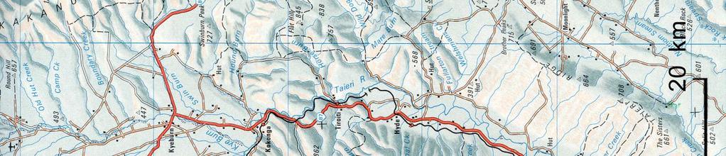
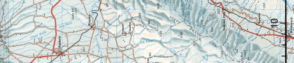
58
59
60
61
62
63
64
65
66
67
68
69
70 APPENDIX A PHASING OF WORK FOR MINING ROUND HILL SOUTHERN PIT
71
72
73
74
75
76
77
78
79
80
81
82 APPENDIX B SLOPE STABILITY ANALYSES FOR MTI EMBANKMENT
83
84
85 ÎÔ ø³
86 ÎÔ ø³
87 ÎÔ ø³
88 ÎÔ ø³
89 ÎÔ ø³
90 ÎÔ ø³
91 ÎÔ ø³
92 ÎÔ ø³
93 ÎÔ ø³
94 ÎÔ ø³
95 ÎÔ ø³
96 ÎÔ ø³
97 ÎÔ ø³
98 APPENDIX C DECONSTRUCTION OF SP11A EMBANKMENT
99
100
101
102
103
104
105
106
107 APPENDIX D SLOPE STABILITY ANALYSES FOR SP10 TSF TAILINGS SURFACE AND EMBANKMENT
108
109 ÎÔ ø³
110 ÎÔ ø³
111
112 ÎÔ ø³
113 ÎÔ ø³
114 ÎÔ ø³
115 ÎÔ ø³
116 APPENDIX E SLOPE STABILITY ANALYSES FOR RECLAIMED TAILINGS STACK
117
118
119
120 ÎÔ ø³
121 ÎÔ ø³
122 ÎÔ ø³
123 APPENDIX F HISTORICAL MOVEMENT OF FOOTWALL FAULT DUE TO MINING ACTIVITY
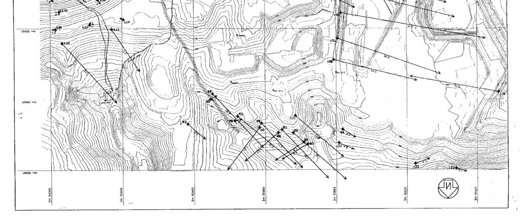
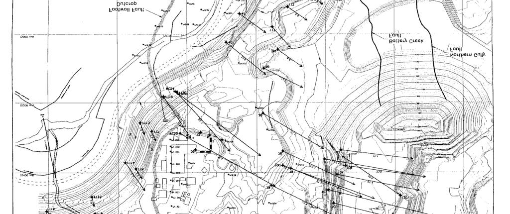
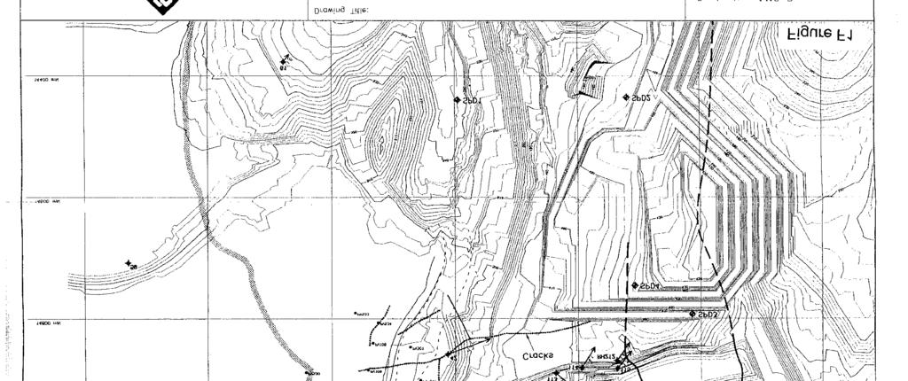
124
Review of static and seismic stability of a cross-valley sand tailings embankment in a high rainfall, high seismicity setting
 Tailings and Mine Waste Management for the 21 st Century 2015 Paper Number: 52 Review of static and seismic stability of a cross-valley sand tailings embankment in a high rainfall, high seismicity setting
Seismic Evaluation of Tailing Storage Facility
 Australian Earthquake Engineering Society 2010 Conference, Perth, Western Australia Seismic Evaluation of Tailing Storage Facility Jonathan Z. Liang 1, David Elias 2 1 Senior Geotechnical Engineer, GHD
ENGINEER S CERTIFICATION OF FAULT AREA DEMONSTRATION (40 CFR )
") PLATTE RIVER POWER AUTHORITY RAWHIDE ENERGY STATION BOTTOM ASH TRANSFER (BAT) IMPOUNDMENTS LARIMER COUNTY, CO ENGINEER S CERTIFICATION OF FAULT AREA DEMONSTRATION (40 CFR 257.62) FOR COAL COMBUSTION RESIDUALS
PLATTE RIVER POWER AUTHORITY RAWHIDE ENERGY STATION BOTTOM ASH TRANSFER (BAT) IMPOUNDMENTS LARIMER COUNTY, CO ENGINEER S CERTIFICATION OF FAULT AREA DEMONSTRATION (40 CFR 257.62) FOR COAL COMBUSTION RESIDUALS
HISTORY OF CONSTRUCTION FOR EXISTING CCR SURFACE IMPOUNDMENT PLANT GASTON ASH POND 40 CFR (c)(1)(i) (xii)
(1)(i) (xii)") HISTORY OF CONSTRUCTION FOR EXISTING CCR SURFACE IMPOUNDMENT PLANT GASTON ASH POND 40 CFR 257.73(c)(1)(i) (xii) (i) Site Name and Ownership Information: Site Name: E.C. Gaston Steam Plant Site Location:
HISTORY OF CONSTRUCTION FOR EXISTING CCR SURFACE IMPOUNDMENT PLANT GASTON ASH POND 40 CFR 257.73(c)(1)(i) (xii) (i) Site Name and Ownership Information: Site Name: E.C. Gaston Steam Plant Site Location:
Numerical analysis of effect of mitigation measures on seismic performance of a liquefiable tailings dam foundation
 Numerical analysis of effect of mitigation measures on seismic performance of a liquefiable tailings dam foundation Yong-Beom Lee, Jorge Castillo Ausenco, USA Aurelian C. Trandafir Fugro GeoConsulting
This report was prepared by Klohn Crippen Consultants Ltd. for Alberta Transportation Central Region under Contract No. CE053/2000.
 Alberta Transportation Central Region #401, 4902 51 Street Red Deer, Alberta T4N 6K8 June 7, 2002 Mr. Melvin Mayfield, P.Eng. Project Engineer Dear Mr. Mayfield: Central Region Landslide Assessment Site
MINISTRY OF ENERGY AND MINES Mines and Mineral Resources. REPORT OF GEOTECHNICAL INSPECTOR (Issued pursuant to Section 15 of the Mines Act)
") MINISTRY OF ENERGY AND MINES Mines and Mineral Resources REPORT OF GEOTECHNICAL INSPECTOR (Issued pursuant to Section 15 of the Mines Act) Name of Property: Permit No.: M-203 General Manager: Company:
MINISTRY OF ENERGY AND MINES Mines and Mineral Resources REPORT OF GEOTECHNICAL INSPECTOR (Issued pursuant to Section 15 of the Mines Act) Name of Property: Permit No.: M-203 General Manager: Company:
Seismic Design of a Hydraulic Fill Dam by Nonlinear Time History Method
 Seismic Design of a Hydraulic Fill Dam by Nonlinear Time History Method E. Yıldız & A.F. Gürdil Temelsu International Engineering Services Inc., Ankara, Turkey SUMMARY: Time history analyses conducted
Central Queensland Coal Project Appendix 4b Geotechnical Assessment. Environmental Impact Statement
 Central Queensland Coal Project Appendix 4b Geotechnical Assessment Environmental Impact Statement GEOTECHNICAL ASSESSMENT OF OPEN CUT MINING ADJACENT TO THE BRUCE HIGHWAY, CENTRAL QUEENSLAND COAL PROJECT
1 INTRODUCTION 1.1 General
 #701 475 Howe Street Vancouver, British Columbia V6C 2B3 August 1, 2014 Robin McCall Wolverine Mine Environmental Superintendent Dear Mr. McCall: 1 INTRODUCTION 1.1 General This letter report presents
IAEA SAFETY STANDARDS Geotechnical Aspects of Site Evaluation and Foundations in NPPs, NS-G-3.6
 IAEA SAFETY STANDARDS Geotechnical Aspects of Site Evaluation and Foundations in NPPs, NS-G-3.6 Regional Workshop on Volcanic, Seismic, and Tsunami Hazard Assessment Related to NPP Siting Activities and
South Dam Quinsam Mine. Submitted to: Hillsborough Resources Limited Quinsam Coal Corporation PO Box 5000 Campbell River, BC V9W 8A3
 2015 ANNUAL DAM SAFETY INSPECTION South Dam Quinsam Mine Submitted to: Hillsborough Resources Limited Quinsam Coal Corporation PO Box 5000 Campbell River, BC V9W 8A3 Attention: Mr. Gary Gould REPORT Reference
[1] Performance of the sediment trap depends on the type of outlet structure and the settling pond surface area.
![[1] Performance of the sediment trap depends on the type of outlet structure and the settling pond surface area.](/thumbs/76/74245181.jpg "[1] Performance of the sediment trap depends on the type of outlet structure and the settling pond surface area.") Sediment Trench SEDIMENT CONTROL TECHNIQUE Type 1 System Sheet Flow Sandy Soils Type 2 System [1] Concentrated Flow Clayey Soils Type 3 System [1] Supplementary Trap Dispersive Soils [1] Performance of
Sediment Trench SEDIMENT CONTROL TECHNIQUE Type 1 System Sheet Flow Sandy Soils Type 2 System [1] Concentrated Flow Clayey Soils Type 3 System [1] Supplementary Trap Dispersive Soils [1] Performance of
CCR Rule Annual Inspection Report (cont.) 2
 2") The inspection findings consisted of maintenance items and items that were not observed to be signs or potential signs of significant structural weakness. No deficiencies or disrupting conditions that
The inspection findings consisted of maintenance items and items that were not observed to be signs or potential signs of significant structural weakness. No deficiencies or disrupting conditions that
IV. ENVIRONMENTAL IMPACT ANALYSIS G. GEOLOGY AND SOILS
 IV. ENVIRONMENTAL IMPACT ANALYSIS G. GEOLOGY AND SOILS The following section is a summary of the geotechnical report conducted for the proposed project. The Report of Geotechnical Investigation Proposed
STRUCTURAL STABILITY ASSESSMENT
 STRUCTURAL STABILITY ASSESSMENT CFR 257.73(d) Bottom Ash Pond Complex Cardinal Plant Brilliant, Ohio October, 2016 Prepared for: Cardinal Operating Company Cardinal Plant Brilliant, Ohio Prepared by: Geotechnical
1.0 INSPECTION ANNUAL INSPECTION, JUNE 29, 2011 CARMACKS COPPER PROJECT, CARMACKS, YUKON. Dear Mr. West-Sells,
 Doc. No. 162 Rev. 0 Mr. Paul West-Sells President & Chief Operating Officer Western Copper Corporation 2060-1111 West Georgia Street Vancouver, BC V6E 4M3 ANNUAL INSPECTION, JUNE 29, 2011 CARMACKS COPPER
Landslide stability analysis using the sliding block method
 Landslide stability analysis using the sliding block method E. Lino, R. Norabuena, M. Villanueva & O. Felix SRK Consulting (Peru) S.A., Lima, Peru A. Lizcano SRK Consulting (Vancouver) S.A., British Columbia,
The results of KCB s site inspection observations and our recommendations for further work are presented herein.
 July 14, 2015 Central Region 401, 4902 51 Street Red Deer, Alberta T4N 6K8 Mr. Tony Penney, P.Eng. Construction Engineer Dear Mr. Penney: June 25, 2015 Site Inspection Report The above site was visited
Omaroro Lower Playing Field - Geotechnical Interpretive Report
 Report Omaroro Lower Playing Field - Geotechnical Interpretive Report Prepared for Wellington Water Limited Prepared by Beca Limited 1 December 2017 Omaroro Lower Playing Field - Geotechnical Interpretive
Tailing Storage at the Fort Knox Mine An Innovative Expansion to Continue a History of Success
 Tailing Storage at the Fort Knox Mine An Innovative Expansion to Continue a History of Success Thomas F. Kerr, P.E. President, Knight Piésold and Co., Denver, USA Peter D. Duryea, Ph.D., P.E. Senior Project
3.18 GEOLOGY AND SOILS
 3.18 GEOLOGY AND SOILS This section discusses geologic resource concerns as they relate to the environment, public safety, and project design both during construction and after completion of the project.
Numerical model comparison on deformation behavior of a TSF embankment subjected to earthquake loading
 Numerical model comparison on deformation behavior of a TSF embankment subjected to earthquake loading Jorge Castillo, Yong-Beom Lee Ausenco, USA Aurelian C. Trandafir Fugro GeoConsulting Inc., USA ABSTRACT
Rock & Aggregate Drop Inlet Protection
 Rock & Aggregate Drop Inlet Protection SEDIMENT CONTROL TECHNIQUE Type 1 System Sheet Flow Sandy Soils Type 2 System [1] Concentrated Flow Clayey Soils Type 3 System Supplementary Trap Dispersive Soils
Guidelines for Site-Specific Seismic Hazard Reports for Essential and Hazardous Facilities and Major and Special-Occupancy Structures in Oregon
 Guidelines for Site-Specific Seismic Hazard Reports for Essential and Hazardous Facilities and Major and Special-Occupancy Structures in Oregon By the Oregon Board of Geologist Examiners and the Oregon
ANALYSIS OF A SLOPE FAILURE IN AN OPEN PIT MINE USING TSLOPE
 ANALYSIS OF A SLOPE FAILURE IN AN OPEN PIT MINE USING TSLOPE 1. Background In 1996 a slope failure occurred at the Round Hill open pit mine, operated by Macraes Mining Company Ltd. The failure as shown
POTENTIAL EFFECTS OF EARTHQUAKE SHAKING ON THE PROPOSED CRRRC LANDFILL
 TECHNICAL MEMORANDUM DATE September 26, 2016 PROJECT No. 1211250045/14000 TO Andrew Evers Ministry of Environment and Climate Change FROM Alan Hull, Paul Smolkin POTENTIAL EFFECTS OF EARTHQUAKE SHAKING
J.H. Campbell Generating Facility Pond A - Location Restriction Certification Report
 J.H. Campbell Generating Facility Pond A - Location Restriction Certification Report Pursuant to: 40 CFR 257.60 40 CFR 257.61 40 CFR 257.62 40 CFR 257.63 40 CFR 257.64 Submitted to: Consumers Energy Company
February 18, 2003 File: NORTH CENTRAL REGION LANDSLIDE ASSESSMENT HWY 43:16 WHITECOURT EAST HILL (NC1) 2002 ANNUAL INSPECTION REPORT
 2002 ANNUAL INSPECTION REPORT") February 18, 2003 File: 15-76-11 Alberta Transportation Room 223, Provincial Building 4709 44 Avenue Stony Plain, Alberta T7Z 1N4 Attention: Mr. Rob Lonson, P.Eng. NORTH CENTRAL REGION LANDSLIDE ASSESSMENT
February 18, 2003 File: 15-76-11 Alberta Transportation Room 223, Provincial Building 4709 44 Avenue Stony Plain, Alberta T7Z 1N4 Attention: Mr. Rob Lonson, P.Eng. NORTH CENTRAL REGION LANDSLIDE ASSESSMENT
Slope Stability Evaluation Ground Anchor Construction Area White Point Landslide San Pedro District Los Angeles, California.
 Slope Stability Evaluation Ground Anchor Construction Area White Point Landslide San Pedro District Los Angeles, California Submitted To: Mr. Gene Edwards City of Los Angeles Department of Public Works
Converse Consultants Geotechnical Engineering, Environmental & Groundwater Science, Inspection & Testing Services
 Converse Consultants Geotechnical Engineering, Environmental & Groundwater Science, Inspection & Testing Services Ms. Rebecca Mitchell Mt. San Antonio College Facilities Planning & Management 1100 North
Impact : Changes to Existing Topography (Less than Significant)
") 4.2 Land Resources 4.2.1 Alternative A Proposed Action Impact 4.2.1-1: Changes to Existing Topography (Less than Significant) Development of the project site would involve grading and other earthwork as
4.2 Land Resources 4.2.1 Alternative A Proposed Action Impact 4.2.1-1: Changes to Existing Topography (Less than Significant) Development of the project site would involve grading and other earthwork as
AGENDA ITEM 6 APPENDIX /0151/DET GROUND WATER & SURFACE WATER MANAGEMENT PLAN
 CAIRNGORMS NATIONAL PARK AUTHORITY Planning Committee Agenda Item 6 Appendix 18 12/10/2018 AGENDA ITEM 6 APPENDIX 18 2018/0151/DET GROUND WATER & SURFACE WATER MANAGEMENT PLAN Dalwhinnie Quarry Ground
Converse Consultants Geotechnical Engineering, Environmental & Groundwater Science, Inspection & Testing Services
 Converse Consultants Geotechnical Engineering, Environmental & Groundwater Science, Inspection & Testing Services July 27, 2017 Ms. Rebecca Mitchell Mt. San Antonio College Facilities Planning & Management
SLOPE STABILITY EVALUATION AND ACCEPTANCE STANDARDS
 INFORMATION BULLETIN / PUBLIC - BUILDING CODE REFERENCE NO.: LAMC 98.0508 Effective: 1-26-84 DOCUMENT NO. P/BC 2002-049 Revised: 11-1-02 Previously Issued As: RGA #1-84 SLOPE STABILITY EVALUATION AND ACCEPTANCE
Hydraulic uplift forces on basements subject to liquefaction
 Hydraulic uplift forces on basements subject to liquefaction N.S. Luxford Babbage Consultants Ltd 2014 NZSEE Conference ABSTRACT: As a result of the 22 February 2011 earthquake in Christchurch a building
LIQUEFACTION OF EARTH EMBANKMENT DAMS TWO CASE HISTORIES: (1) LIQUEFACTION OF THE EMBANKMENT SOILS, AND (2) LIQUEFACTION OF THE FOUNDATIONS SOILS
 LIQUEFACTION OF THE EMBANKMENT SOILS, AND (2) LIQUEFACTION OF THE FOUNDATIONS SOILS") LIQUEFACTION OF EARTH EMBANKMENT DAMS TWO CASE HISTORIES: (1) LIQUEFACTION OF THE EMBANKMENT SOILS, AND (2) LIQUEFACTION OF THE FOUNDATIONS SOILS Antonio Fernandez, Ph.D. 1 ABSTRACT Paul C. Rizzo Associates,
LIQUEFACTION OF EARTH EMBANKMENT DAMS TWO CASE HISTORIES: (1) LIQUEFACTION OF THE EMBANKMENT SOILS, AND (2) LIQUEFACTION OF THE FOUNDATIONS SOILS Antonio Fernandez, Ph.D. 1 ABSTRACT Paul C. Rizzo Associates,
Location. Mt Owen Complex. Overview. Mine Layout. Mining Method. Mitsubishi Lecture. In-Pit Lowwall Dump Design and Stability at Mt Owen Mine
 Location In-Pit Lowwall Dump Design and Stability at Mt Owen Mine Wayne Bartlett Senior Engineering Geologist Mt Owen Complex Overview In the past Mt Owen Mine lowwall dumps have failed. Lowwall dumps
Construction Exits Rock pads
 Construction Exits Rock pads SEDIMENT CONTROL TECHNIQUE Type 1 System Sheet Flow Sandy Soils Type 2 System Concentrated Flow [1] Clayey Soils Type 3 System Supplementary Trap Dispersive Soils [1] Minor
SLOPE STABILITY EVALUATION AND ACCEPTANCE STANDARDS
 INFORMATION BULLETIN / PUBLIC - BUILDING CODE REFERENCE NO.: LABC 7006.3, 7014.1 Effective: 01-01-2017 DOCUMENT NO.: P/BC 2017-049 Revised: 12-21-2016 Previously Issued As: P/BC 2014-049 SLOPE STABILITY
Big Rivers Electric Corporation Disposal of Coal Combustion Residuals (CCR) from Electric Utilities Final Rule CCR Impoundment Liner Assessment Report
 from Electric Utilities Final Rule CCR Impoundment Liner Assessment Report") Big Rivers Electric Corporation Disposal of Coal Combustion Residuals (CCR) from Electric Utilities Final Rule CCR Impoundment Liner Assessment Report CCR Surface Impoundment Information Name: Operator:
Big Rivers Electric Corporation Disposal of Coal Combustion Residuals (CCR) from Electric Utilities Final Rule CCR Impoundment Liner Assessment Report CCR Surface Impoundment Information Name: Operator:
Seismic Stability of Tailings Dams, an Overview
 Seismic Stability of Tailings Dams, an Overview BY Gonzalo Castro, Ph.D., P.E. Principal International Workshop on Seismic Stability of Tailings Dams Case Western Reserve University, November 2003 Small
Geotechnical issues in seismic assessments: When do I need a geotechnical specialist?
 Geotechnical issues in seismic assessments: When do I need a geotechnical specialist? B.H. Rama & S.J. Palmer Tonkin & Taylor Ltd (T+T), Wellington, New Zealand. 2016 NZSEE Conference ABSTRACT: The Canterbury
GEOLOGY, SOILS, AND SEISMICITY
 4.9 GEOLOGY, SOILS, AND SEISMICITY 4.9.1 Introduction Information about the geological conditions and seismic hazards in the study area was summarized in the FEIR, and was based on the Geotechnical Exploration
RESERVOIR DRAWDOWN RATES/RESERVOIR DRAWDOWN TEST Iron Gate, Copco (I & II), and JC Boyle Dams
, and JC Boyle Dams") TECHNICAL MEMORANDUM No. 1 TO: Michael Bowen California Coastal Conservancy Geotechnical & Earthquake Engineering Consultants CC: Eric Ginney Philip Williams & Associates PREPARED BY: Paul Grant SUBJECT:
TECHNICAL MEMORANDUM No. 1 TO: Michael Bowen California Coastal Conservancy Geotechnical & Earthquake Engineering Consultants CC: Eric Ginney Philip Williams & Associates PREPARED BY: Paul Grant SUBJECT:
Liquefaction assessments of tailings facilities in low-seismic areas
 Page 1 Liquefaction assessments of tailings facilities in low-seismic areas Holly Rourke SRK Consulting, Perth, WA, Australia Caroline Holmes SRK Consulting, Perth, WA, Australia This paper was first presented
CHRACTERISTICS OF LANDSLIDE OCCURRED IN LOPARE, BOSNIA AND HERZEGOVINA
 CHRACTERISTICS OF LANDSLIDE OCCURRED IN LOPARE, BOSNIA AND HERZEGOVINA Jun Sugawara 1 and Takao Aizawa 2 1 WorleyParsons, Australia 2 Suncoh Consultants, Japan ABSTRACT This paper presents results of detailed
Slope Stability Model of the Questa Rock Pile Phase 2
 2 Proceedings Tailings and Mine Waste 2011 Slope Stability Model of the Questa Rock Pile Phase 2 Murray Fredlund SoilVision Systems Ltd., Saskatoon, Canada Haihua Lu SoilVision Systems Ltd., Saskatoon,
Introduction and Background
 Introduction and Background Itasca Consulting Group, Inc. (Itasca) has been participating in the geomechanical design of the underground 118-Zone at the Capstone Minto Mine (Minto) in the Yukon, in northwestern
GEOTECHNICAL ENGINEERING II. Subject Code : 06CV64 Internal Assessment Marks : 25 PART A UNIT 1
 GEOTECHNICAL ENGINEERING II Subject Code : 06CV64 Internal Assessment Marks : 25 PART A UNIT 1 1. SUBSURFACE EXPLORATION 1.1 Importance, Exploration Program 1.2 Methods of exploration, Boring, Sounding
1 PROJECT BACKGROUND. August 14, Alberta Transportation Central Region #401, Street Red Deer, Alberta T4N 6K8
 August 14, 2013 Alberta Transportation Central Region #401, 4902 51 Street Red Deer, Alberta T4N 6K8 Mr. Dennis Grace, P.Eng. Construction Engineer Dear Mr. Grace: Central Region Geohazard Assessment 2013
Stone Outlet Sediment Trap
 3.12 Sediment Control Description: A stone outlet sediment trap is a small detention area formed by placing a stone embankment with an integral stone filter outlet across a drainage swale for the purpose
CONTROLLING FACTORS BASIC ISSUES SAFETY IN OPENCAST MINING WITH SPECIAL REFERENCE TO SLOPE STABILITY
 SAFETY IN OPENCAST MINING WITH SPECIAL REFERENCE TO SLOPE STABILITY CONTROLLING FACTORS Dr. J C. JHANWAR Sr. Principal Scientist CSIR-Central Institute of Mining & Fuel Research Regional Centre, Nagpur
Calibration of Seepage and Stability Models for analysis of Dams and Levees. Francke C Walberg Consulting Geotechnical Engineer, AECOM
 Calibration of Seepage and Stability Models for analysis of Dams and Levees Francke C Walberg Consulting Geotechnical Engineer, AECOM Focus Use of models for; Evaluation of existing dams and levees Rehabilitation
SOIL INVESTIGATION REPORT. PROPOSED HOUSING DEVELOPMENT PROJECT Coral Spring, Trelawny, Jamaica.
 SOIL INVESTIGATION REPORT PROPOSED HOUSING DEVELOPMENT PROJECT Coral Spring, Trelawny, Jamaica. Prepared for: FCS Consultants 7a Barbados Avenue Kingston 5, Jamaica Prepared by: NHL Engineering Limited
January 17, 2008 File:
 January 17, 2008 File: 15-85-73 Alberta Infrastructure and Transportation Room 301, Provincial Building 9621-96 Avenue Peace River, Alberta T8S 1T4 Attention: Mr. Ed Szmata PEACE REGION (SWAN HILLS AREA)
Further Research into Methods of Analysing the October 2000 Stability of Deep Open Pit Mines EXECUTIVE SUMMARY
 EXECUTIVE SUMMARY This report presents the results of a program of further research into the use of a combined approach of numerical and centrifuge modeling in assessing the stability of deep open pit
Date: April 2, 2014 Project No.: Prepared For: Mr. Adam Kates CLASSIC COMMUNITIES 1068 E. Meadow Circle Palo Alto, California 94303
 City of Newark - 36120 Ruschin Drive Project Draft Initial Study/Mitigated Negative Declaration Appendix C: Geologic Information FirstCarbon Solutions H:\Client (PN-JN)\4554\45540001\ISMND\45540001 36120
U-Shaped Sediment Traps
 U-Shaped Sediment Traps SEDIMENT CONTROL TECHNIQUE Type 1 System Sheet Flow Sandy Soils Type 2 System Concentrated Flow Clayey Soils [1] Type 3 System Supplementary Trap Dispersive Soils [1] Generally
WHAT SEISMIC HAZARD INFORMATION THE DAM ENGINEERS NEED FROM SEISMOLOGISTS AND GEOLOGISTS?
 WHAT SEISMIC HAZARD INFORMATION THE DAM ENGINEERS NEED FROM SEISMOLOGISTS AND GEOLOGISTS? Martin WIELAND 1 ABSTRACT For large dam projects a site-specific seismic hazard analysis is usually recommended.
NOA ASSESSMENT HARRIS QUARRY MENDOCINO COUNTY, CALIFORNIA TABLE OF CONTENTS
 NOA ASSESSMENT HARRIS QUARRY MENDOCINO COUNTY, CALIFORNIA TABLE OF CONTENTS Introduction... 1 Scope of Services... 1 Project Location and Description... 1 Geologic Setting... 1 Regional Geology... 1 Site
DRAFT ONONDAGA LAKE CAPPING AND DREDGE AREA AND DEPTH INITIAL DESIGN SUBMITTAL H.4 SEISMIC SLOPE STABILITY ANALYSES
 DRAFT ONONDAGA LAKE CAPPING AND DREDGE AREA AND DEPTH INITIAL DESIGN SUBMITTAL H.4 SEISMIC SLOPE STABILITY ANALYSES Parsons P:\Honeywell -SYR\444576 2008 Capping\09 Reports\9.3 December 2009_Capping and
 Rock Slope Analysis Small and Large Scale Failures Mode of Failure Marklands Test To establish the possibility of wedge failure. Plane failure is a special case of wedge failure. Sliding along
Ground Improvement by Dynamic Compaction at a Tailings Disposal Facility
 Missouri University of Science and Technology Scholars' Mine International Conferences on Recent Advances in Geotechnical Earthquake Engineering and Soil Dynamics 2010 - Fifth International Conference
I. Hulls E. Woods A. Creighton
 Slope Stability 2013 P.M. Dight (ed) 2013 Australian Centre for Geomechanics, Perth, ISBN 978-0-9870937-5-2 https://papers.acg.uwa.edu.au/p/1308_40_wines/ D.R. Wines Itasca Australia Pty Ltd, Australia
Coarse Sediment Traps
 Coarse Sediment Traps SEDIMENT CONTROL TECHNIQUE Type 1 System Sheet Flow Sandy Soils Type 2 System [1] Concentrated Flow Clayey Soils [2] Type 3 System Supplementary Trap Dispersive Soils [1] Though primarily
Run 028 (Note: error in UKC at start of exercise due incorrect tide input then corrected ok.)
") Run 027 RNZ Full Bridge Simulation Run Plots Final Report Be-Software August 2016 Prepared for Royal Haskoning DHV on behalf of Refining New Zealand Limited 27 Run 028 (Note: error in UKC at start of exercise
Run 027 RNZ Full Bridge Simulation Run Plots Final Report Be-Software August 2016 Prepared for Royal Haskoning DHV on behalf of Refining New Zealand Limited 27 Run 028 (Note: error in UKC at start of exercise
Evaluation of Geotechnical Hazards
 Evaluation of Geotechnical Hazards by Geoffrey R. Martin Appendix B: Evaluation of Geotechnical Hazards Describes Evaluation Procedures Soil Liquefaction Soil Settlement Surface Fault Rupture Flooding
Geology, Soils, and Seismicity
 Section 3.8 Geology, Soils, and Seismicity Introduction This section generally evaluates the effects of the alternatives analyzed in this Supplemental DEIS with regard to geology, soils and seismicity.
For personal use only
 ASX ANNOUNCEMENT / MEDIA RELEASE 16 th August, 2013 ASX:ABU Trial Mining Continues and Commissioning of the Old Pirate Processing Plant is Underway ABM Resources NL ( ABM or The Company ) presents an update
14 Geotechnical Hazards
 Volume 2: Assessment of Environmental Effects 296 14 Geotechnical Hazards Overview This Chapter provides an assessment of the underlying geotechnical conditions to identify: any potential liquefaction
THE MINISTRY OF ENERGY AND ENERGY INDUSTRIES MINERALS DIVISION MINE DESIGN TEMPLATE OPERATOR NAME: OPERATOR ADDRESS: PHONE NUMBER: FACSIMILE:
 THE MINISTRY OF ENERGY AND ENERGY INDUSTRIES MINERALS DIVISION MINE DESIGN TEMPLATE 1.0 GENERAL INFORMATION OPERATOR NAME: OPERATOR ADDRESS: PHONE NUMBER: FACSIMILE: NAME OF CONTACT: CELLULAR PHONE: EMAIL
2. Initial Summary of Preliminary Expert Opinion of Converse and Psomas Reports
 UNITED WALNUT TAXPAYERS PRELIMINARY REVIEW OF NEGATIVE GEOTECHNICAL AND GEOLOGICAL ASPECTS OF CONSTRUCTING EARTHFILL PAD FOR A SOLAR FARM ON THE WEST PARCEL - DRAFT 1. Introduction A licensed Engineering
GEOLOGY AND SOILS. This chapter summarizes geologic and geotechnical aspects of the site as they relate to the Project.
 9 GEOLOGY AND SOILS INTRODUCTION This chapter summarizes geologic and geotechnical aspects of the site as they relate to the Project. This chapter utilizes information from the following reports prepared
Te Kuha Mining Operation Geotechnical Concept Study for Stevenson Mining
 Te Kuha Mining Operation Geotechnical Concept Study for Stevenson Mining Prepared For Mike Coleman CEO for Stevenson Mining Prepared By Christian Mans BSc, PGD, AusIMM(CP), RPEQ, NZGS Geotechnical Engineer
Answers: Internal Processes and Structures (Isostasy)
") Answers: Internal Processes and Structures (Isostasy) 1. Analyse the adjustment of the crust to changes in loads associated with volcanism, mountain building, erosion, and glaciation by using the concept
Answers: Internal Processes and Structures (Isostasy) 1. Analyse the adjustment of the crust to changes in loads associated with volcanism, mountain building, erosion, and glaciation by using the concept
TABLE 1 CAPSULE SUMMARIES OF GEOTECHNICAL DOCUMENTS
 Evaluation of Future Tailings Disposal, 50 years of Additional Disposal, Utah Copper Division (UCD) Tailings Pond Near Magna, Utah, Kennecott Minerals Company (Dames and Moore, August 1983) Geotechnical
Instructor : Dr. Jehad Hamad. Chapter (7)
") Instructor : Dr. Jehad Hamad Chapter (7) 2017-2016 Soil Properties Physical Properties Mechanical Properties Gradation and Structure Compressibility Soil-Water Relationships Shear Strength Bearing Capacity
Instructor : Dr. Jehad Hamad Chapter (7) 2017-2016 Soil Properties Physical Properties Mechanical Properties Gradation and Structure Compressibility Soil-Water Relationships Shear Strength Bearing Capacity
CHAPTER GEOLOGICALLY HAZARDOUS AREAS Applicability Regulations.
 CHAPTER 19.07 GEOLOGICALLY HAZARDOUS AREAS 19.07.010 Applicability. Geologically hazardous areas may pose a threat to the health and safety of citizens when incompatible development is sited in areas of
APPENDIX H. Groundwater Assessment (GWS Limited)
") H APPENDIX H Groundwater Assessment (GWS Limited) Project Martha Assessment of Groundwater Effects 43 Moresby Ave Waihi 3610 New Zealand Report Prepared for: OceanaGold NZ Ltd 20 th April 2018 FINAL REPORT
H APPENDIX H Groundwater Assessment (GWS Limited) Project Martha Assessment of Groundwater Effects 43 Moresby Ave Waihi 3610 New Zealand Report Prepared for: OceanaGold NZ Ltd 20 th April 2018 FINAL REPORT
3.0 SUMMARY OF POTENTIAL GEOTECHNICAL IMPACTS AND MITIGATION MEASURES
 3.0 SUMMARY OF POTENTIAL GEOTECHNICAL IMPACTS AND MITIGATION MEASURES This section summarizes the principal geotechnical conditions that occur in the project area. The potential impact that each condition
3.12 Geology and Topography Affected Environment
 3 Affected Environment and Environmental Consequences 3.12 Geology and Topography 3.12.1 Affected Environment 3.12.1.1 Earthquakes Sterling Highway MP 45 60 Project Draft SEIS The Kenai Peninsula is predisposed
B805 TEMPORARY EROSION AND SEDIMENT CONTROL MEASURES - OPSS 805
 B805 MEASURES - OPSS 805 805.1 GENERAL Construction activities frequently remove protective cover and expose soil to accelerated rates of erosion. Sediments generated thereby can be conveyed via runoff
Engineer. Engineering. Engineering. (in-ja-neer ) A person trained and skilled in any of the various branches of engineering: a civil engineer
 A person trained and skilled in any of the various branches of engineering: a civil engineer") Engineer (in-ja-neer ) A person trained and skilled in any of the various branches of engineering: a civil engineer (Random House Webster s College Dictionary, 1991) CE100 Introduction to Civil Geotechnical
Engineer (in-ja-neer ) A person trained and skilled in any of the various branches of engineering: a civil engineer (Random House Webster s College Dictionary, 1991) CE100 Introduction to Civil Geotechnical
The key natural hazards relevant to the Project area relate to seismic activity and flood risk.
 21. NATURAL HAZARDS Overview The key natural hazards relevant to the Project area relate to seismic activity and flood risk. Seismic activity, including ground shaking and liquefaction, is a significant
The Owl Creek Pit Part 1: Relocating Mine Rock from Surface Stockpiles to the Pit to Mitigate Acid Drainage
 The Owl Creek Pit Part 1: Relocating Mine Rock from Surface Stockpiles to the Pit to Mitigate Acid Drainage Jeff Martin 1, Thomas Sulatycky 2, Brian Fraser 1, Rina Parker 1, Bruce Rodgers 1 and Ron Nicholson
Earthquake Commission Darfield Earthquake Recovery Geotechnical Factual Report New Brighton
 REPORT Earthquake Commission Darfield Earthquake Recovery Geotechnical Factual Report New Brighton REPORT Earthquake Commission Darfield Earthquake Recovery Geotechnical Factual Report New Brighton Report
IV. ENVIRONMENTAL IMPACT ANALYSIS E. GEOLOGY AND SOILS
 IV. ENVIRONMENTAL IMPACT ANALYSIS E. GEOLOGY AND SOILS The following section is a summary of the geotechnical report conducted for the Proposed Project. The Geotechnical Engineering Investigation (the
Geosynthetics Applications and Performance Reviews Select Case Histories
 Geosynthetics Applications and Performance Reviews Select Case Histories Debora J. Miller, Ph.D., P.E.; Dean B. Durkee,, Ph.D., P.E.; Michael A. Morrison, P.E., David B. Wilson, P.E., and Kevin Smith,
Table of Contents Chapter 1 Introduction to Geotechnical Engineering 1.1 Geotechnical Engineering 1.2 The Unique Nature of Soil and Rock Materials
 Table of Contents Chapter 1 Introduction to Geotechnical Engineering 1.1 Geotechnical Engineering 1.2 The Unique Nature of Soil and Rock Materials 1.3 Scope of This Book 1.4 Historical Development of Geotechnical
Location Restriction Demonstration
 Location Restriction Demonstration R.M. Heskett Station Coal Ash Landfill Prepared for Montana-Dakota Utilities Company October 2018 Minneapolis, MN, Bismarck, ND Location Restrictions Demonstration October
Portia Gold Mine Update
 1 Portia Gold Mine Update South Australian Resources & Energy Investment Conference 20 April 2016 Dr Chris Giles Managing Director Havilah Resources LimitedDr Chris Giles, MD 20 April 2016 Dr Chris Giles
Natural hazards in Glenorchy Summary Report May 2010
 Natural hazards in Glenorchy Summary Report May 2010 Contents Glenorchy s hazardscape Environment setting Flood hazard Earthquakes and seismic hazards Hazards Mass movement Summary Glossary Introduction
Type 1 System Sheet Flow Sandy Soils Type 2 System Concentrated Flow Clayey Soils Type 3 System [1] Supplementary Trap Dispersive Soils
![Type 1 System Sheet Flow Sandy Soils Type 2 System Concentrated Flow Clayey Soils Type 3 System [1] Supplementary Trap Dispersive Soils](/thumbs/77/76519623.jpg "Type 1 System Sheet Flow Sandy Soils Type 2 System Concentrated Flow Clayey Soils Type 3 System [1] Supplementary Trap Dispersive Soils") Sediment Weirs SEDIMENT CONTROL TECHNIQUE Type 1 System Sheet Flow Sandy Soils Type 2 System Concentrated Flow Clayey Soils Type 3 System [1] Supplementary Trap Dispersive Soils [1] Type 3 classification
Sediment Weirs SEDIMENT CONTROL TECHNIQUE Type 1 System Sheet Flow Sandy Soils Type 2 System Concentrated Flow Clayey Soils Type 3 System [1] Supplementary Trap Dispersive Soils [1] Type 3 classification
HISTORY OF CONSTRUCTION FOR EXISTING CCR SURFACE IMPOUNDMENT PLANT GADSDEN ASH POND 40 CFR (c)(1)(i)-(xii)
(1)(i)-(xii)") HISTORY OF CONSTRUCTION FOR EXISTING CCR SURFACE IMPOUNDMENT PLANT GADSDEN ASH POND 40 CFR 257.73(c)(1)(i)-(xii) (i) Site Name and Ownership Information: Site Name: Site Location: Site Address: Gadsden
HISTORY OF CONSTRUCTION FOR EXISTING CCR SURFACE IMPOUNDMENT PLANT GADSDEN ASH POND 40 CFR 257.73(c)(1)(i)-(xii) (i) Site Name and Ownership Information: Site Name: Site Location: Site Address: Gadsden
Mark Hawley, Piteau Associates Engineering Ltd. John Cunning, Golder Associates Ltd.
 Introducing: GUIDELINES FOR MINE WASTE DUMP AND STOCKPILE DESIGN Editors: Mark Hawley, Piteau Associates Engineering Ltd. John Cunning, Golder Associates Ltd. 8 November 2017 Sponsorship 8 November 2017
design, construction, operation, and maintenance of the BAP is consistent with recognized and generally accepted good engineering standards.
 design, construction, operation, and maintenance of the BAP is consistent with recognized and generally accepted good engineering standards. In addition to the field inspection, Associated Engineers, Inc.
STATEMENT OF EVIDENCE OF SHANE LANDER (GEOTECHNICAL - QD2) ON BEHALF OF MURPHYS DEVELOPMENTS LIMITED
 ON BEHALF OF MURPHYS DEVELOPMENTS LIMITED") IN THE MATTER of the Housing Accords and Special Housing Areas Act 2013 ("HASHAA") AND IN THE MATTER of Proposed Qualifying Development Application ("QD2") for 125 Murphys Road, Flat Bush BETWEEN Murphys
IN THE MATTER of the Housing Accords and Special Housing Areas Act 2013 ("HASHAA") AND IN THE MATTER of Proposed Qualifying Development Application ("QD2") for 125 Murphys Road, Flat Bush BETWEEN Murphys
MEDIA RELEASE OCEANAGOLD ANNOUNCES FURTHER DOWN DIP EXTENSIONS OF MINERALISATION AT PANEL 2: FRASERS UNDERGROUND MINE
 MEDIA RELEASE 21 July 2010 OCEANAGOLD ANNOUNCES FURTHER DOWN DIP EXTENSIONS OF MINERALISATION AT PANEL 2: FRASERS UNDERGROUND MINE (MELBOURNE) OceanaGold Corporation (ASX: OGC, TSX: OGC, NZX: OGC) ( the
For personal use only
 29 July 2011 The Manager Company Announcements Office Australian Securities Exchange Exchange Centre 20 Bridge Street SYDNEY NSW 2000 Dear Sir Quarterly Activities Report for the period ended 30 June 2011