PRESTACK DEPTH MIGRATION VELOCITY MODEL BUILDING IN COMPLEX CARPATHIANS GEOLOGY
|
|
|
- Blanche Moore
- 6 years ago
- Views:
Transcription
1 A C T A G E O P H Y S I C A P O L O N I C A Vol. 53, no. 3, pp PRESTACK DEPTH MIGRATION VELOCITY MODEL BUILDING IN COMPLEX CARPATHIANS GEOLOGY Krzysztof Karol ŚLIŻ AGH University of Science and Technology Faculty of Geology, Geophysics and Environmental Protection Al. Mickiewicza 30, Kraków, Poland Geofizyka Kraków Ltd. ul. Łukasiewicza 3, Kraków, Poland krzysztof.sliz@geofizyka.krakow.pl Abstract Carpathians geology is very complex and seismic horizons are highly deformed by tectonic movements, existence of thrusts, numerous faults and fracture zones. Therefore, the geological interpretation beneath the overthrust is uncertain and wells cannot be reliably located. Under complex geological conditions, time migration algorithms generate errors resulting from strong horizontal velocity changes. Moreover, the proper focusing of dissipated energy requires application of a PreStack Depth Migration (PreSDM). Proper depth imaging depends on appropriateness of velocity model used for PreSDM. Unfortunately the complexity of velocity changes limits the effectiveness of conventional velocity analysis techniques. The article focuses on PreSDM velocity model building process for data acquired in complex overthrust environment. The method is based on dual usage of tomographic inversion together with combination of non-seismic information. Combination of tomographic results with well velocities increases convergence of the method. It also limits an ambiguity and improves reliability of final velocity model. To justify the proposed method, the border value of possible tomographic velocity updates was evaluated. The method was tested on two different datasets acquired in the Polish Carpathians. Key words: PreStack Depth Migration, velocity model building, seismic tomography, overthrust, Carpathians.
2 312 K.K. ŚLIŻ 1. INTRODUCTION PreStack Depth Migration (PreSDM) is a robust method for obtaining proper image of complex subsurface. In areas of rapid lateral and vertical velocity changes, energy is dispersed in such a way that conventional stacking with hyperbolic moveout diminishes both noise and signal. The PreSDM focuses scattered energy by moving it to a proper subsurface position. Only when energy is properly focused, stacking improves the quality of signals and eliminates noise. There are several situations where PreSDM could bring good effects. Some of them are environments of complex sedimentation structures, robust tectonics, presence of salt or basalt bodies and, for some migration codes, influences of anisotropy. Applying a proper velocity model to PreSDM, we can expect significant improvement of seismic data quality (both resolution and continuity) and proper spatial structural positioning. Additionally, which is not commonly acknowledged, the velocity model created for PreSDM carries direct knowledge about geology. For these reasons, velocity estimation process is the main task in depth imaging. Fortunately, iterative PreSDM is a good tool for velocity analysis due to its high sensitivity to velocity errors. Data quality in areas of complicated geology is usually very poor. This complicates the process of velocity model building. Conventional methods fail in the areas of tectonic deformations and strong lateral velocity changes. These problems make velocity model building a difficult and ambiguous process (Lines et al., 2000). Methods for migration velocity analysis In general, the process of velocity model building can be split into two phases: preparation of initial model and its updating. The initial model should be simple but it should describe general velocity trend. The detailed velocity changes are found during the Migration Velocity Analysis (MVA). The concept of using PreStack Depth Migration for velocity analysis is related to the idea that correct velocity used to PreSDM results in flat reflections for all offsets on the Common Reflection Points (CRPs). When images from different offsets are not lined up, a residual moveout can be used to correct the velocity model. The MVA methods usually require picking of residual arrival times and inversion of picks for velocity changes (Jones, 2003). The criteria used in velocity model determination are based on the flatness of pre-stack migrated gathers or the quality of a stacked image. Unfortunately, there can be several subsurface velocity models, which straighten migrated gathers equally well. This leads to a problem of receiving an unique solution. There are three commonly known approaches to migration velocity analysis: Deregovski Loop (DL) (Deregowski, 1990) and its modification, Layer Striping Method (Bleistein and Liu, 1992) and global methods (Stork, 1992). Each of them is useful under special circumstances. DL is the fastest and the easiest approach but it is valid only when velocity variations are medium. Layer Striping Method accumulates mis-
3 PRESTACK DEPTH MIGRATION VELOCITY MODEL 313 takes made just at the beginning and is useful in areas of visible seismic horizons on common offset planes. Global velocity updating methods like tomography perform velocity updating for the whole subsurface, or at least a large portion of it. The process uses data from a large number of migrated gathers simultaneously. Reflection tomography In tomographic approach to the inverse problem, the medium velocity is determined by minimizing misfit function between measured and computed travel-times. The solution is usually computed by introducing deviation in travel-times. Deviation amplitude cannot be too big, which results in limitations of finding a new model which would be too different from the input one. Besides, there are several other problems which must be handled by reflection tomography. Firstly, picking reflected events from seismic signal is much more difficult than the estimation of first arrivals in refraction tomography. The events are frequently distorted by coherent noise and dislocations. Secondly, the inversion problem is very ill-posed. The raypath coverage in reflection method is sparser, and therefore there is a possibility of multiple solutions and a problem of uniqueness (Kasina, 2001). Finally, the construction of raypaths strongly relies on the reflector position, on both depths and slopes (Liu, 1995). Accordingly, the problem of convergence and ambiguity of the model is a general issue. In spite of these difficulties, tomographic inversion is a convenient and reliable method to obtain a good and detailed velocity model and it is reasonable to use it for determination of rapid velocity changes in complex regions. The final result depends on boundary conditions and proper initial velocity model is among the most important ones. This is why the key to success is the ability to construct a proper starting model. Then the results of tomographic inversion should converge to a plausible geological solution. 2. DATA AND GEOLOGY The method was tested on 2 datasets from different areas acquired in southeast Poland (Fig. 1). Both regions are situated on the edge of the Carpathian overthrust. All profiles were situated perpendicular to the Carpathian overthrust. The general direction of lines was from S-W to N-E. Acquisition was made in 1992 and 1993 by Geofizyka Kraków Ltd. using vibrator sources; CDP coverage varied from 24 to 64 and maximum offset was from 1240 to 2550 m, length being from 12 to 22 km. The well information was sparse and unevenly distributed (Górecki et al., 2004). The Outer Carpathians are built of sandy-shaly rocks of Cretaceous through Oligocen age. These rocks together with older folded Miocene deposits are thrust over autochthonous deposits of younger Miocene of the Carpathian Foredeep. The Flysch Carpathians in their marginal, northern part lie on Miocene rocks of the Carpathian Foredeep, whereas in the southern part they probably rest on the diversified Mesozoic-Paleozoic and Precambrian basement (Karnkowski, 1993). The Carpathian over-

.")
4 314 K.K. ŚLIŻ???? Fig. 1. The map of the area where test data were gathered. Solid lines indicate profiles chosen for modelling. Yellow markers show position of well with velocity information. Black dashed line indicates schematic frontier of the Carpathian overthrust. Scale: 1 cm = 5 km. thrust is built of strongly folded, cut by tectonic zones, flysch sediments in which alternating silty-clayey and sandstone layers of varied thickness dominate. Layers build numerous thrust sheets and scales. They are formed of partly differentiated sediments showing evidence that they originated in various sedimentary basins (Krzywiec, 1999). Partly due to these reasons, velocity changes in the Carpathian environment are severe but sometimes can be associated with specific scales. In contrast, Miocene environment is less complex but velocities can be disturbed by stratygraphic changes, possible gas accumulations and some general, regional dislocations. Deposits of autochtonous Miocene in the presented area are prospective for finding high quality gas accumulations (Karnkowski, 1993). 3. METHOD The key to the success of tomographic inversion is a proper starting model. Unfortunately, there are several reasons why traditional initial model building techniques (model from RMS velocities or based on gradient functions) fail in overthrusted areas. Some of them are as follows:
5 PRESTACK DEPTH MIGRATION VELOCITY MODEL 315 low resolution of stacking velocities, fast lateral velocity changes and sparse coverage of well information, strong influence of noise and steep horizons for estimated velocities, problems with assigning a single gradient function for a given zone. The author assumed that correct model can be built when the lateral resolution of initial model will be close to smoothed velocity function obtained from wells. For this reason, the first phase of the method defines proper trend of lateral velocity changes. The obtained result can be combined with well velocities. When appropriate starting velocity model is created, the proper border conditions appear for tomographic inversion. The proposed method is composed of dual usage of tomographic inversion and iterative adjustment of the model to changes in structural interpretation. The first phase of tomographic inversions is based on prototype model. In the very first stage of velocity updates, the main interest is in reliability of structural image obtained by PreSDM and in correct horizontal velocities trend. Furthermore, image obtained in the first phase of the method is used to define structural polygons. The polygons are employed for edition of tomographic inversion results and for future combination of migration velocities with well information. In the second phase of the method, the resolution of model is increased and inversions are continued until the results converge. Proper criterion of convergence for iterative migration velocity analysis is difficult to define. In practice, quality of seismic image is the main condition. An improvement of horizons continuity (which is a result of increased CRP gathers flatness) is critical for approval of velocity model. However, good velocity model should also respect geological conditions (range of velocity changes and proper structural geometry). Unfortunately, it is hard and sometimes impossible to combine both conditions. The author employed difference between results of sequential iterations of tomographic inversion for evaluation of its convergence (Fig. 2). If results of succeeding inversions give gradually smaller velocity updates, the inversion converges. If updates are smaller than ±250 m/s, the process can be considered as finished. The value of ±250 m/s was found by performing tomographic inversion on synthetic (modelled) data (Fig. 3). For modelling process, the finite difference acoustic wave equation solution was used. Modelled data represented similar acquisition geometry and geology as the real, tested data (in Fig. 1 profiles chosen for modelling are shown). The criterion of uniqueness is much harder to define. It can be checked only by matching PreSDM result to the wells. This is why, the function of minimizing difference between PreSDM depths and wells was chosen as a criterion of uniqueness. The difference between imaging velocities and the well velocity was also analyzed. Unfortunately, this condition is rarely met and it is impossible to match result of PreSDM with depths measured in wells. Usually, the anisotropy is blamed for this phenomenon. For this reason, an additional assumption was made: the velocity model is more unique if PreSDM gives simpler geometry of horizons.


 Difference between")

 differences are")
6 316 K.K. ŚLIŻ a) b) Fig. 2. The convergence criterion. Differences (in m/s) between models in different phase of the method. (a) Difference between iteration 2 and 1 of the first phase; (b) Difference between iteration 2 and 1 of the second phase; (c) Difference between last and previous iteration of the second phase. Note that on panel; (c) differences are smaller than 250 m/s. The obtained low velocity anomaly is indicated by the arrow. c)

7 PRESTACK DEPTH MIGRATION VELOCITY MODEL 317 Fig. 3. Evaluation of tomographic inversion results, PreSDM, done on modelled data. True velocity model smoothed by operator m was used. On the picture, tomographic inversion result is shown. The visible anomalies cannot be associated with real velocity changes. Note that the accuracy of the method for this type of the data is ±250 m/s. Process of prototype velocity model building Prototype velocity model is used for the first phase of tomographic inversion. It can be built by the gradient s functions or RMS stacking velocities can be used. Prototype velocity model based on stacking velocity. Stacking velocities are converted to interval velocities in depth. Then the process of adjustment to geological values and structural interpretation is performed. The anomaly velocities are edited. This phase is iterative and feed backed by PostSDM results (in the beginning) and later by PreSDM. Special attention should be paid to unwanted structural anomalies. If observed, severe smoothing of RMS and interval velocities must be performed. The process of smoothing and RMS velocity edition is driven by structural polygons and initial PostSDMs/PreSDMs are repeated several times until a reasonable structural definition is observed. Prototype velocity model based on gradient functions. Alternatively to RMS velocities, gradient functions can be used to create a prototype velocity model. The functions are described as: V(x, z) = V 0 + k x x + k z z, where coefficients k x and k z represent horizontal and vertical gradients computed from average velocity or acoustic logging. In each well, several k z are derived with respect to velocity changes in main geological
8 318 K.K. ŚLIŻ layers. Then the coefficients k x are computed in such a way that k z z functions can be smoothly converted from one well into another. Unfortunately, usage of these functions may lead to ambiguity since they are based on the process of averaging velocities inside previously defined layers. For this reason, proper definition of zones where velocity changes linearly and calibration of wells to the seismic image are critical at this stage of work (Jarzyna et al., 1999). One of the main advantages of gradient functions is the possibility of creating consistent model of 2D multiple lines. First phase of tomographic inversion In the first phase of the method the prototype model is updated by tomographic invermethod, improvements in seismic image quality sions and lateral velocity changes are defined. Prototype model in complex environment is far from being correct. One solution for handling non-uniqueness at this stage of the method is to use geologic information to constrain the model. Very often the velocity varies smoothly within geological formations. If it is possible to identify key formations on migrated sections, a smooth velocity function can be sought within each formation while allowing higher velocity changes across interfaces separating different layers. Therefore, strong constrains (edition of minimum and maximum changes in the model and smoothing) can be applied to tomographic inversions results inside previously identified formations. During the first phase of the were observed, although tomographic updates could not converge. Results from one iteration to another changed significantly and it was impossible to obtain ±250 m/s limit. Besides, each velocity update leaded to strong changes in structural interpretation. Fortunately, proper horizontal velocity gradient could be found inside each defined geological formation. Additionally, despite of implementation of strong smoothing, the resolution of model increased, which resulted in narrowing the difference between well velocities and prototype model. Apart from this, better definition and continuity of horizons were received at this stage of the work. This led to more reliable structural definition of the model. The number of iteration was data-dependent but usually 2-6 iterations were sufficient. Velocity model building Important part of the method is combination of well velocities (hard data) with model obtained during first phase of the tomographic inversions (soft data). This is performed in geostatistical manner; weights are assigned to data according to their reliability and distance from wells. The whole process is performed utilizing idea of pseudo-well logs. They represent vertical parameter changes in a possible position of well. Location of pseudo-wells is introduced to stabilize process of inter-polation of true well s velocity (Fig. 4). Usually, pseudo-well velocities differ from real ones. Besides, the real wells are usually located in uneven pattern, which usually causes


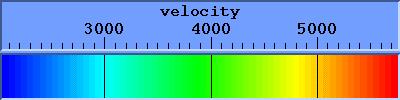
9 PRESTACK DEPTH MIGRATION VELOCITY MODEL 319 o o o Fig. 4. Combination of well velocities with functions derived from first phase of tomographic inversions. Approximated wells positions are shown by solid lines, whereas dashed lines indicate pseudo-wells. It can be noticed that first phase velocities (surrounding wells) are close to values obtained from well logs. The velocity scale is in m/s. several problems during interpolation process. In polygons defined during the first phase of the method, velocity wells are matched with pseudo wells and, if necessary, scaling is performed. During scaling process the lateral velocity gradient defined during the first phase is preserved. The procedure of interpolation and combination is guided by structural interpretation which keeps structurally consistent lateral velocity changes. Second phase of tomographic inversion The second phase of tomographic updates utilizes initial velocity model described above (Fig. 5b). Usually 3 to 5 iterations of tomographic inversion are necessary to obtain the final result. Relatively small number of iterations is needed, mainly due to definition of proper vertical and horizontal velocity gradients. During iterative tomographic updates, the resolution and plausibility of the model increase and small velocity changes can be defined. This leads to geologically valuable velocities which can

10 320 K.K. ŚLIŻ a) b) c)
 computed with model without low velocity anomaly")

.")
 Prototype model based on edited, structurally smoothed stacking velocities.")
 Initial velocity model used for the second phase of the method.")
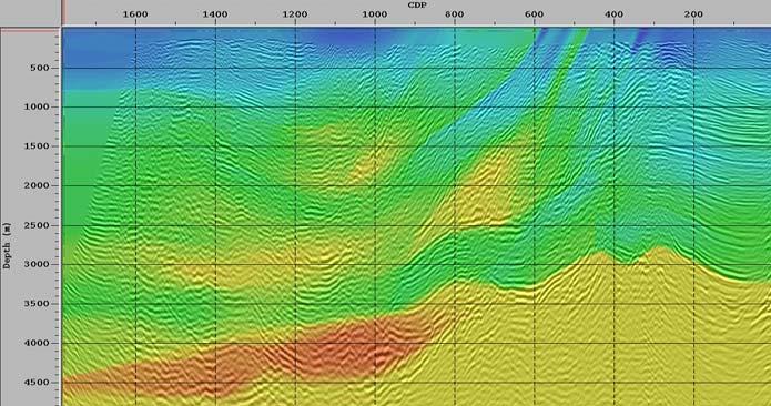
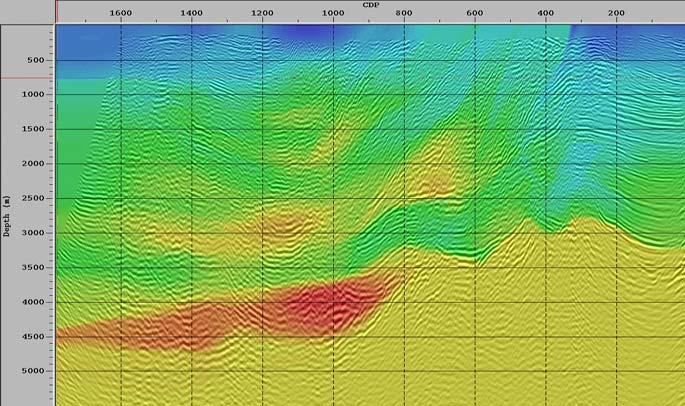
11 PRESTACK DEPTH MIGRATION VELOCITY MODEL 321 a) 500 CDP Fi g. 6. Comparison of PreSDM results: (a) computed with model without low velocity anomaly shown in Fig. 2c; (b) computed with discovered anomaly. Arrow indicates one of the horizons where MVA was conducted. Obtained changes may indicate interpretational values of velocity model shown in Fig. 5c Fig. 5 (see page 320). Changes in velocity models during different phases of the method. (a) Prototype model based on edited, structurally smoothed stacking velocities. It can be seen that some zones (indicated by arrows) can be correlated to final velocity model. (b) Initial velocity model used for the second phase of the method. (c) Final velocity model. Arrows indicate the most significant changes related to the prototype model. The same velocity scale was used for all panels. b)


12 322 K.K. ŚLIŻ a) b) Fig. 7. Comparison of PreSDM realized with velocity model obtained by the proposed method with post stack time migration: (a) Final PreSDM results. Arrows indicate the most evident changes in comparison to time migration; (b) Time migrations results.
13 PRESTACK DEPTH MIGRATION VELOCITY MODEL 323 be used in more detailed stratigraphic interpretation (Fig. 2c and Fig. 6). It is also possible to gradually increase the offset range (in both the process of ray tracing and residual moveout analysis). This helps to diminish possible velocity errors and improves final seismic image (Fagin, 1999). 4. RESULTS Construction of a velocity model for PreStack Depth Migration was conducted in two phases. Tomographic inversion results were combined with well velocities. It was possible to develop good interpretational velocity distribution and improve quality of seismic image. PreSDM correctly focused dispersed energy, which allowed for quality improvement of the inner Carpathian horizons, the bottom of the Carpathian overthrust, Miocene horizons, and Miocene substratum of different age (Fig. 7). Previously invisible faults and structures were also imaged. This would not be possible without a proper velocity model. 5. CONCLUSIONS The quality of initial velocity distribution has the greatest influence on tomographic inversion process. A good initial model limits ambiguity and increases convergenc e of tomographic solutions. Therefore, an initial model plays key role in a process of migration velocity analysis for complex structures. In the case of tomographic inversion, a wrong provisional velocity distribution makes it impossible to obtain convergent results. The approach used in this study estimated the initial velocity field by means of combination of tomographic results with well velocities. Successive iterations are performed until the obtained structural model could be accepted and tomographic inversion velocities updates reached limits of ±250 m/s. The tomographic inversion requires the imposition of geological constraints and manual edition of results of each iteration. The proposed method allows to obtain geologically plausible velocity model even in the areas where wells are not uniformly located. Significantly small velocity changes received during final tomographic inversion to some extent prove the correctness of the final solution. When analyzing structural changes on the seismic sections after final PreSDM, one can see a varied geometry of reflections beneath the Carpathian overthrust. As compared to the time migration result, a characteristic horizontal shift of culmination of structures can be observed after depth migration (Górecki et al., 2004). PreSDM is a powerful method and is proven to give results of a remarkable quality. As mentioned previously, such results are obtained only provided that a proper velocity model is used.
14 324 K.K. ŚLIŻ A c k n o w l e d g e m e n t s. The paper represents part of author s PhD research. The AGH University of Science and Technology and the author acknowledge support of this investigation by Landmark Graphic software via the Landmark University Grant. Research was partly conducted in the framework of grants led by Professor Wojciech Górecki. References Bleistein, N., and Z. Liu, 1992, Velocity analysis by residual moveout, 1992 SEG Annual Meeting, Expanded Abstracts, p Deregowski, S.M., 1990, Common offset migration and velocity analysis, First Break 8, Domagała, K., K. Lisowski, M. Oniszk, A. Wójcicki, T. Adamczyk and A. Maksym, 2002, Integrated interpretation of geophysical and geological data in Hermanowa, Babicy and Strzyżowa Area (in Polish), Archives of the PGNiG, Geonafta, Jasło (unpublished). Fagin, S., 1999, Model-Based Depth Imaging, Society of Exploration Geophysicists, Tulsa, 173 pp. Górecki, W., M. Stefaniuk, T. Maćkowski, B. Reicher, K.K. Śliż, A. Maksym and J. Siupik, 2004, Joint interpretation of seismic and MT data beneath the Polish Carpathians overthrust, EAGE Annual Meeting, Paris, Expanded Abstracts. Jarzyna, J., M. Bała and T. Zorski, 1999, Well logging methods logging and interpretation (in Polish), Uczeln. Wyd. Nauk.-Dydakt., AGH, Kraków 19, 91. Jones, I.F., 2003, A review of 3D PreSDM model building techniques, First Break 3, 53. Karnkowski, P., 1993, Oil and gas fields in Poland, Carpathians and Carpathian foredeep (in Polish), Towarzystwo Geosynoptyków Geos, AGH, Kraków 247. Kasina, Z., 2001, Seismic Tomography (in Polish), Wyd. Inst. GSMiE PAN, Kraków, Krzywiec, P., 1999, Tectonic evolution of Miocene formation in east part of the Carpathian foredeep (in Polish). In: Analysis of Tertiary Carpathian Basin, Prace Państw. Inst. Geol Lines, R.L., S.H. Gray and D.C. Lawton, 2000, Depth imaging of foothills seismic data, Canadian SEG Publ., Calgary, Liu, Z., 1995, Migration velocity analysis, PhD Thesis, Center for Wave Phenomena, Colorado School of Mines, Golden CO, USA 168, 78, 82. Stork, C., 1992, Reflection tomography in postmigrated domain, Geophysics 57, Received 5 April 2004 Received in revised form 16 February 2005 Accepted 22 February 2005
A Southern North Sea Multi-Survey presdm using Hybrid Gridded Tomography
 A Southern North Sea Multi-Survey presdm using Hybrid Gridded Tomography Ian Jones* GX Technology, Egham, United Kingdom ijones@gxt.com Emma Evans and Darren Judd GX Technology, Egham, United Kingdom and
Tu N Fault Shadow Removal over Timor Trough Using Broadband Seismic, FWI and Fault Constrained Tomography
 Tu N118 05 Fault Shadow Removal over Timor Trough Using Broadband Seismic, FWI and Fault Constrained Tomography Y. Guo* (CGG), M. Fujimoto (INPEX), S. Wu (CGG) & Y. Sasaki (INPEX) SUMMARY Thrust-complex
Summary. Introduction
 Detailed velocity model building in a carbonate karst zone and improving sub-karst images in the Gulf of Mexico Jun Cai*, Hao Xun, Li Li, Yang He, Zhiming Li, Shuqian Dong, Manhong Guo and Bin Wang, TGS
Summary. Introduction
 Multi-layer tomography and its application for improved depth imaging Patrice Guillaume, Steve Hollingworth*, Xiaoming Zhang, Anthony Prescott, Richard Jupp, Gilles Lambaré, Owen Pape, CGGVeritas Summary
SeisLink Velocity. Key Technologies. Time-to-Depth Conversion
 Velocity Calibrated Seismic Imaging and Interpretation Accurate Solution for Prospect Depth, Size & Geometry Accurate Time-to-Depth Conversion was founded to provide geologically feasible solutions for
C031 Quantifying Structural Uncertainty in Anisotropic Depth Imaging - Gulf of Mexico Case Study
 C031 Quantifying Structural Uncertainty in Anisotropic Depth Imaging - Gulf of Mexico Case Study K. Osypov* (WesternGeco), D. Nichols (WesternGeco), Y. Yang (WesternGeco), F. Qiao (WesternGeco), M. O'Briain
Enhancing Sub Basalt Imaging Using Depth Domain Processing
 Enhancing Sub Basalt Imaging Using Depth Domain Processing A.K.Sarkar*, P.V.Rao, S.Panigrahi and S.R.M.Karnawat Regional Computer Centre, ONGC, Vadodara, India E-mail:sarkararun@hotmail.com Summary Processing
Velocity Update Using High Resolution Tomography in Santos Basin, Brazil Lingli Hu and Jianhang Zhou, CGGVeritas
 Lingli Hu and Jianhang Zhou, CGGVeritas Summary The exploration interest in the Santos Basin offshore Brazil has increased with the large deep water pre-salt discoveries, such as Tupi and Jupiter. As the
TOM 2.6. SEG/Houston 2005 Annual Meeting 2581
 Oz Yilmaz* and Jie Zhang, GeoTomo LLC, Houston, Texas; and Yan Shixin, PetroChina, Beijing, China Summary PetroChina conducted a multichannel large-offset 2-D seismic survey in the Yumen Oil Field, Northwest
The i-stats: An Image-Based Effective-Medium Modeling of Near-Surface Anomalies Oz Yilmaz*, GeoTomo LLC, Houston, TX
 The i-stats: An Image-Based Effective-Medium Modeling of Near-Surface Anomalies Oz Yilmaz*, GeoTomo LLC, Houston, TX Summary Near-surface modeling for statics corrections is an integral part of a land
Downloaded 05/01/17 to Redistribution subject to SEG license or copyright; see Terms of Use at
 Mapping Imbricate Structures in the Thrust Belt of Southeast Turkey by Large-Offset Seismic Survey Oz Yilmaz*, Anatolian Geophysical, Istanbul, Turkey; and Serdar Uygun, Ali Ölmez, and Emel Çalı, Turkish
ANGLE-DEPENDENT TOMOSTATICS. Abstract
 ANGLE-DEPENDENT TOMOSTATICS Lindsay M. Mayer, Kansas Geological Survey, University of Kansas, Lawrence, KS Richard D. Miller, Kansas Geological Survey, University of Kansas, Lawrence, KS Julian Ivanov,
Velocity model building in complex media by multi-layer non-linear slope tomography. Summary Introduction Non-linear slope tomography
 Velocity model building in complex media by multi-layer non-linear slope tomography. Patrice Guillaume, Jean-Philippe Montel*, Xiaoming Zhang, Gilles Lambaré, Anthony Prescott, Matthieu Reinier, Richard
Anisotropic Depth Migration and High-Resolution Tomography in Gulf of Mexico: A Case History
 Anisotropic Depth Migration and High-Resolution Tomography in Gulf of Mexico: A Case History Gary Rodriguez, Sherry Yang, Diane Yang, Quincy Zhang, Steve Hightower, TGS Summary We present a case study
Seismic tomography with co-located soft data
 Seismic tomography with co-located soft data Mohammad Maysami and Robert G. Clapp ABSTRACT There is a wide range of uncertainties present in seismic data. Limited subsurface illumination is also common,
Depth Imaging through Surface Carbonates: A 2D example from the Canadian Rocky Mountains
 Depth Imaging through Surface Carbonates: A 2D example from the Canadian Rocky Mountains Yong Hua* University of Calgary, Calgary, AB yhua@ucalgary.ca and Don Lawton University of Calgary, Calgary, AB,
The 2D/3D i-stats Workflow for Image-Based Near-Surface Modeling for Statics Corrections
 The 2D/3D i-stats Workflow for Image-Based Near-Surface Modeling for Statics Corrections Öz Yilmaz CTO, GeoTomo LLC With the i-stats workflow, you no longer need first-break picking as for traveltime tomography,
SUMMARY ANGLE DECOMPOSITION INTRODUCTION. A conventional cross-correlation imaging condition for wave-equation migration is (Claerbout, 1985)
") Comparison of angle decomposition methods for wave-equation migration Natalya Patrikeeva and Paul Sava, Center for Wave Phenomena, Colorado School of Mines SUMMARY Angle domain common image gathers offer
Comparison of angle decomposition methods for wave-equation migration Natalya Patrikeeva and Paul Sava, Center for Wave Phenomena, Colorado School of Mines SUMMARY Angle domain common image gathers offer
H005 Pre-salt Depth Imaging of the Deepwater Santos Basin, Brazil
 H005 Pre-salt Depth Imaging of the Deepwater Santos Basin, Brazil Y. Huang* (CGGVeritas), D. Lin (CGGVeritas), B. Bai (CGGVeritas), S. Roby (CGGVeritas) & C. Ricardez (CGGVeritas) SUMMARY Several discoveries,
ANISOTROPIC PRESTACK DEPTH MIGRATION: AN OFFSHORE AFRICA CASE STUDY
 Copyright 000 by the Society of Exploration Geophysicists ANISOTROPIC PRESTACK DEPTH MIGRATION: AN OFFSHORE AFRICA CASE STUDY Philippe Berthet *, Paul Williamson *, Paul Sexton, Joachim Mispel * * Elf
Static Corrections for Seismic Reflection Surveys
 Static Corrections for Seismic Reflection Surveys MIKE COX Volume Editors: Series Editor: Eugene F. Scherrer Roland Chen Eugene F. Scherrer Society of Exploration Geophysicists Tulsa, Oklahoma Contents
Tomography for Static Corrections and Prestack Depth Imaging
 Tomography for Static Corrections and Prestack Depth Imaging Xianhuai Zhu, Ph.D. Fusion Petroleum Technologies Inc. 25231 Grogan's Mill Road, Suite 175 The Woodlands, TX 77380, USA Summary Turning-ray
Daniele Colombo* Geosystem-WesternGeco, Calgary, AB M.Virgilio Geosystem-WesternGeco, Milan, Italy.
 Seismic Imaging Strategies for Thrust-Belt Exploration: Extended Offsets, Seismic/Gravity/EM simultaneous Joint-Inversion and Anisotropic Gaussian Beam Pre-Stack Depth Migration Daniele Colombo* Geosystem-WesternGeco,
Complex-beam Migration and Land Depth Tianfei Zhu CGGVeritas, Calgary, Alberta, Canada
 Page 1 of 10 Home Articles Interviews Print Editions Complex-beam Migration and Land Depth Tianfei Zhu CGGVeritas, Calgary, Alberta, Canada DECEMBER 2012 FOCUS ARTICLE Summary Gaussian-beam depth migration
A Study of Uphole to Determine the Shooting Medium for Seismic Reflection Survey at Himalayan Foot Hill Area
 A Study of Uphole to Determine the Shooting Medium for Seismic Reflection Survey at Himalayan Foot Hill Area Summary Binode Chetia Frontier Basins, ONGC, Dehradun E-mail: chetia_binode@ongc.co.in Acquiring
So I have a Seismic Image, But what is in that Image?
 P-513 So I have a Seismic Image, But what is in that Image? Dr. Nader C. Dutta, Schlumberger Introduction and background Migration involves repositioning of returned signals in a seismic experiment to
The seismic response to strong vertical velocity change
 10 th Biennial International Conference & Exposition P-073 The seismic response to strong vertical velocity change Ian F. Jones, ION GX Technology Summary Conventional seismic data processing, whether
Depth Imaging for Unconventional Reservoir Characterization: Canadian Plains Case Study
 Depth Imaging for Unconventional Reservoir Characterization: Canadian Plains Case Study Bill Goodway 1, Greg Purdue 1, Shiang Yong Looi 2, Lijuan (Kathy) Du 2, Mark Rowland 2 1 Apache Canada, 2 Schlumberger
A Petroleum Geologist's Guide to Seismic Reflection
 A Petroleum Geologist's Guide to Seismic Reflection William Ashcroft WILEY-BLACKWELL A John Wiley & Sons, Ltd., Publication Contents Preface Acknowledgements xi xiii Part I Basic topics and 2D interpretation
Chapter 1. Introduction EARTH MODEL BUILDING
 Chapter 1 Introduction Seismic anisotropy in complex earth subsurface has become increasingly important in seismic imaging due to the increasing offset and azimuth in modern seismic data. To account for
Azimuthal Velocity Analysis of 3D Seismic for Fractures: Altoment-Bluebell Field
 Azimuthal Velocity Analysis of 3D Seismic for Fractures: Altoment-Bluebell Field Khaled Al Dulaijan and Gary F. Margrave CREWES Summary The 3D seismic data was acquired within Bluebell Field, the eastern
Shear wave statics in 3D-3C : An alternate approach
 P-157 C. B. Yadava*, M Singh, Kuldeep Prakash, Kunal Niyogi GEOPIC, Oil & Natural Gas Corporation Ltd, Dehradun Summary 3D-3C data was acquired in Sayan-Tadkeshwar area of Cambay basin to bring out sand
Investigating fault shadows in a normally faulted geology
 Investigating fault shadows in a normally faulted geology Sitamai Ajiduah* and Gary Margrave CREWES, University of Calgary, sajiduah@ucalgary.ca Summary Fault shadow poses a potential development risk
Noise suppression and multiple attenuation using full-azimuth angle domain imaging: case studies
 first break volume 33, June 2015 special topic Noise suppression and multiple attenuation using full-azimuth angle domain imaging: case studies Aleksander Inozemtsev 1*, Zvi Koren 1 and Alexander Galkin
We A10 12 Common Reflection Angle Migration Revealing the Complex Deformation Structure beneath Forearc Basin in the Nankai Trough
 We A10 12 Common Reflection Angle Migration Revealing the Complex Deformation Structure beneath Forearc Basin in the Nankai Trough K. Shiraishi* (JAMSTEC), M. Robb (Emerson Paradigm), K. Hosgood (Emerson
Seismic Inversion on 3D Data of Bassein Field, India
 5th Conference & Exposition on Petroleum Geophysics, Hyderabad-2004, India PP 526-532 Seismic Inversion on 3D Data of Bassein Field, India K.Sridhar, A.A.K.Sundaram, V.B.G.Tilak & Shyam Mohan Institute
Stanford Exploration Project, Report 115, May 22, 2004, pages
 Stanford Exploration Project, Report 115, May 22, 2004, pages 249 264 248 Stanford Exploration Project, Report 115, May 22, 2004, pages 249 264 First-order lateral interval velocity estimates without picking
Detecting fractures using time-lapse 3C-3D seismic data
 data Zimin Zhang, Don C. Lawton and Robert R. Stewart ABSTRACT This report presents the interpretation of time-lapse 3C-3D seismic data for fracture detection in a Saskatchewan potash mine. Seismic interpretation
Tu N Estimation of Uncertainties in Fault Lateral Positioning on 3D PSDM Seismic Image - Example from the NW Australian Shelf
 Tu N118 06 Estimation of Uncertainties in Fault Lateral Positioning on 3D PSDM Seismic Image - Example from the NW Australian Shelf S. Birdus* (CGG), V. Ganivet (CGG), A. Artemov (CGG), R. Teakle (Chevron)
Improved image aids interpretation: A case history
 Ye Zheng, Scott Cheadle (Veritas GeoServices, Calgary, Canada) Glenn M. Rising (Perez Companc Norcen Corod, Venezuela) SUMMARY The Oritupano-Leona 3D of Eastern Venezuela was originally acquired and processed
Summary. We present the results of the near-surface characterization for a 3D survey in thrust belt area in Sharjah, United Arab Emirates.
 Near-surface characterization, challenges, and solutions for high-density, high-productivity, Alexander Zarkhidze*, Claudio Strobbia, Abdallah Ibrahim, WesternGeco; Luis Viertel Herrera, Abdulla Al Qadi,
Synthetic seismic modelling and imaging of an impact structure
 Modelling and imaging of an impact structure Synthetic seismic modelling and imaging of an impact structure Matteo Niccoli ABSTRACT A geologic depth and velocity model of an impact crater was created and
An empirical method for estimation of anisotropic parameters in clastic rocks
 An empirical method for estimation of anisotropic parameters in clastic rocks YONGYI LI, Paradigm Geophysical, Calgary, Alberta, Canada Clastic sediments, particularly shale, exhibit transverse isotropic
30, Cracow, Poland;
 INTERPRETATION OF THE FLYSCH COVER STRUCTURE BASED ON MAGNETOTELLURIC DATA EXAMPLES OF SIEKLÓWKA NAWSIE AND DOMARADZ ALBIGOWA CROSS SECTIONS (POLISH OUTER CARPATHIANS) M. STEFANIUK 1,2 and A. ŚLĄCZKA 3
23855 Rock Physics Constraints on Seismic Inversion
 23855 Rock Physics Constraints on Seismic Inversion M. Sams* (Ikon Science Ltd) & D. Saussus (Ikon Science) SUMMARY Seismic data are bandlimited, offset limited and noisy. Consequently interpretation of
VELOCITY REDUCTION - A POINT IN VELOCITY MODEL BUILDING FOR PRE-STACK KIRCHOFF DEPTH MIGRATION
 Physical Geography; Cartography; Geographic Information Systems & Spatial Planing VELOCITY REDUCTION - A POINT IN VELOCITY MODEL BUILDING FOR PRE-STACK KIRCHOFF DEPTH MIGRATION Dr. Maya Grigorova University
J.A. Haugen* (StatoilHydro ASA), J. Mispel (StatoilHydro ASA) & B. Arntsen (NTNU)
, J. Mispel (StatoilHydro ASA) & B. Arntsen (NTNU)") U008 Seismic Imaging Below "Dirty" Salt J.A. Haugen* (StatoilHydro ASA), J. Mispel (StatoilHydro ASA) & B. Arntsen (NTNU) SUMMARY Base and sub salt seismic imaging is still an unresolved issue. To solve
U008 Seismic Imaging Below "Dirty" Salt J.A. Haugen* (StatoilHydro ASA), J. Mispel (StatoilHydro ASA) & B. Arntsen (NTNU) SUMMARY Base and sub salt seismic imaging is still an unresolved issue. To solve
Imaging complex structure with crosswell seismic in Jianghan oil field
 INTERPRETER S CORNER Coordinated by Rebecca B. Latimer Imaging complex structure with crosswell seismic in Jianghan oil field QICHENG DONG and BRUCE MARION, Z-Seis, Houston, Texas, U.S. JEFF MEYER, Fusion
Model Building Complexity in the Presence of a Rugose Water Bottom Gippsland Basin Australia
 Model Building Complexity in the Presence of a Rugose Water Bottom Gippsland Basin Australia Paul Bouloudas, Apache Energy, Juergen Fruehn, ION GX Technology Introduction Situated offshore south-eastern
Anisotropic tomography for TTI and VTI media Yang He* and Jun Cai, TGS
 media Yang He* and Jun Cai, TGS Summary A simultaneous anisotropic tomographic inversion algorithm is developed. Check shot constraints and appropriate algorithm preconditioning play an important role
Repeatability in geophysical data processing: A case study of seismic refraction tomography.
 Available online at www.scholarsresearchlibrary.com Archives of Applied Science Research, 2012, 4 (5):1915-1922 (http://scholarsresearchlibrary.com/archive.html) ISSN 0975-508X CODEN (USA) AASRC9 Repeatability
Improved Interpretability via Dual-sensor Towed Streamer 3D Seismic - A Case Study from East China Sea
 Improved Interpretability via Dual-sensor Towed Streamer 3D Seismic - A Case Study from East China Sea S. Rongfu (CNOOC Shanghai), C. Hua (CNOOC Shanghai), W. Yun (CNOOC Shanghai), Z. Yabin (CNOOC Shanghai),
G002 An Integrated Regional Framework for Seismic Depth Imaging in the Deepwater Gulf of Mexico
 G002 An Integrated Regional Framework for Seismic Depth Imaging in the Deepwater Gulf of Mexico M. Davidson (Fugro Multi Client Services), M. Leander (Fugro Multi Client Services), K. Mohn (Fugro Multi
Summary. Surface-wave analysis and inversion
 Building a near-surface velocity model in the South Ghadames basin: surface-wave inversion to solve complex statics D. Boiero*, P. Marsden, V. Esaulov, A. Zarkhidze, and P. Vermeer, WesternGeco Summary
Th N Seismic Imaging in Gas Obscured Areas - Q Anomaly Detection and Q Migration Applied to Broadband Data
 Th N107 11 Seismic Imaging in Gas Obscured Areas - Q Anomaly Detection and Q Migration Applied to Broadband Data A. Castiello* (ION GXT), Y. Ren (ION GXT), S. Greenwood (ION GXT), T. Martin (ION GXT),
2010 SEG SEG Denver 2010 Annual Meeting
 Anisotropic model building with wells and horizons: Gulf of Mexico case study comparing different approaches Andrey Bakulin*, Olga Zdraveva, Yangjun (Kevin) Liu, Kevin Lyons, WesternGeco/Schlumberger Summary
MUHAMMAD S TAMANNAI, DOUGLAS WINSTONE, IAN DEIGHTON & PETER CONN, TGS Nopec Geological Products and Services, London, United Kingdom
 Geological and Geophysical Evaluation of Offshore Morondava Frontier Basin based on Satellite Gravity, Well and regional 2D Seismic Data Interpretation MUHAMMAD S TAMANNAI, DOUGLAS WINSTONE, IAN DEIGHTON
Th P7 02 A Method to Suppress Salt-related Converted Wave Using 3D Acoustic Modelling
 Th P7 0 A Method to Suppress Salt-related Converted Wave Using 3D Acoustic Modelling J. Kumar* (Petroleum Geo-Services), M. Salem (ENI E&P), D.E. Cegani (ENI E&P) Summary Converted waves can be recorded
Chapter 7. Seismic imaging. 7.1 Assumptions and vocabulary
 Chapter 7 Seismic imaging Much of the imaging procedure was already described in the previous chapters. An image, or a gradient update, is formed from the imaging condition by means of the incident and
Shallow P and S velocity structure, Red Deer, Alberta
 Shallow P and S velocity structure, Red Deer, Alberta P & S velocity structure Don C. Lawton, Meredith A. McArthur, Rachel T. Newrick and Sarah E. Trend ABSTRACT A multioffset vertical seismic profile
Feasibility and design study of a multicomponent seismic survey: Upper Assam Basin
 P-276 Summary Feasibility and design study of a multicomponent seismic survey: Upper Assam Basin K.L.Mandal*, R.K.Srivastava, S.Saha, Oil India Limited M.K.Sukla, Indian Institute of Technology, Kharagpur
Sub Basalt Imaging Using Low Frequency Processing and Angle stack In Saurashtra Region, Western India
 5th Conference & Exposition on Petroleum Geophysics, Hyderabad-2004, India PP 90-94 Sub Basalt Imaging Using Low Frequency Processing and Angle stack In Saurashtra Region, Western India A.K.Sarkar & R.Mohan
Delineating a sandstone reservoir at Pikes Peak, Saskatchewan using 3C seismic data and well logs
 Delineating a sandston reservoir at Pikes Peak Delineating a sandstone reservoir at Pikes Peak, Saskatchewan using 3C seismic data and well logs Natalia L. Soubotcheva and Robert R. Stewart ABSTRACT To
Imaging complex structure in seismic reflection data using prestack depth migration: case study of Olua area of the Niger Delta, Nigeria
 International Research Journal of Geology and Mining (IRJGM) (2276-6618) Vol. 2(7) pp. 199-204, September 2012 Available online http://www.interesjournals.org/irjgm Copyright 2012 International Research
Summary. Introduction
 Xian Qiang*, Liu Yonglei, Lv Dong, An Haiting, He Xiaosong, Li Haiyin, Xiao Yong, Zhou Chenguang, Xu Jianyang, Dong Lei,and Mao Xianyu,BGP,CNPC Summary Although high density, FAZ(Full azimuth) seismic
3D beam prestack depth migration with examples from around the world
 A Publication of Petroleum Geo-Services Vol. 8 No. 8 August 2008 3D beam prestack depth migration with examples from around the world Introduction In 1999 AGS specialized in 2D seismic depth processing.
Interval anisotropic parameters estimation in a least squares sense Case histories from West Africa
 P-263 Summary Interval anisotropic parameters estimation in a least squares sense Patrizia Cibin*, Maurizio Ferla Eni E&P Division (Milano, Italy), Emmanuel Spadavecchia - Politecnico di Milano (Milano,
Pre Stack Imaging To Delineate A New Hydrocarbon Play A Case History
 5th Conference & Exposition on Petroleum Geophysics, Hyderabad-2004, India PP 375-379 Pre Stack Imaging To Delineate A New Hydrocarbon Play A Case History D. Srinivas, T.R. Murali Mohan, Ashwani Lamba,
We Improved Salt Body Delineation Using a new Structure Extraction Workflow
 We-08-08 Improved Salt Body Delineation Using a new Structure Extraction Workflow A. Laake* (WesternGeco) SUMMARY Current salt imaging workflows require thorough geological understanding in the selection
Downloaded 09/10/15 to Redistribution subject to SEG license or copyright; see Terms of Use at
 The role of legacy seismic in exploring new offshore hydrocarbon provinces or can you teach old data new tricks (technologies)? Howard Nicholls, Lauren Penn, Anna Marszalek, Paolo Esestime, Karyna Rodriguez,
FloatSeis Technologies for Ultra-Deep Imaging Seismic Surveys
 FloatSeis Technologies for Ultra-Deep Imaging Seismic Surveys 25 th January, 2018 Aleksandr Nikitin a.nikitin@gwl-geo.com Geology Without Limits Overview 2011-2016 GWL Acquired over 43000 km 2D seismic
Multiple horizons mapping: A better approach for maximizing the value of seismic data
 Multiple horizons mapping: A better approach for maximizing the value of seismic data Das Ujjal Kumar *, SG(S) ONGC Ltd., New Delhi, Deputed in Ministry of Petroleum and Natural Gas, Govt. of India Email:
P066 Duplex Wave Migration for Coal-bed Methane Prediction
 P066 Duplex Wave Migration for Coal-bed Methane Prediction N. Marmalevskyi* (Ukrainian State Geological Prospecting Institute), A. Antsiferov (UkrNIMI), Z. Gornyak (Ukrainian State Geological Prospecting
The Estimation of PS Wave Statics By Using SCDCC + Stack Power Method
 The Estimation of PS Wave Statics By Using SCDCC + Stack Power Method ABSTRACT Summary Aimin Xue * Petrol Sound Geoservices. 8, MacEwan Ridge Close, N.W., Calgary, Alberta T3K3A7, Canada. aiminx@telus.net
3D VTI traveltime tomography for near-surface imaging Lina Zhang*, Jie Zhang, Wei Zhang, University of Science and Technology of China (USTC)
") Downloaded 01/03/14 to 16.01.198.34. Redistribution subject to SEG license or copyright; see Terms of Use at http://library.seg.org/ 3D VTI traveltime tomography for near-surface imaging Lina Zhang*, Jie
Downloaded 01/03/14 to 16.01.198.34. Redistribution subject to SEG license or copyright; see Terms of Use at http://library.seg.org/ 3D VTI traveltime tomography for near-surface imaging Lina Zhang*, Jie
Th Guided Waves - Inversion and Attenuation
 Th-01-08 Guided Waves - Inversion and Attenuation D. Boiero* (WesternGeco), C. Strobbia (WesternGeco), L. Velasco (WesternGeco) & P. Vermeer (WesternGeco) SUMMARY Guided waves contain significant information
Fracture characterization from scattered energy: A case study
 Fracture characterization from scattered energy: A case study Samantha Grandi K., Sung Yuh, Mark E. Willis, and M. Nafi Toksöz Earth Resources Laboratory, MIT. Cambridge, MA. Total Exploration & Production.
Chałupki Dębniańskie Field: Improving Drilling Success in Shallow Gas Reservoirs with VectorSeis
 1 Chałupki Dębniańskie Field: Improving Drilling Success in Shallow Gas Reservoirs with VectorSeis ABSTRACT Summary E. Gruszczyk, Z. Trzesniowski and P. Misiaczek Geofizyka Krakow, Sp.z o.o., Krakow, Poland
Building more robust low-frequency models for seismic impedance inversion
 first break volume 34, May 2016 technical article Building more robust low-frequency models for seismic impedance inversion Amit Kumar Ray 1 and Satinder Chopra 1* Abstract Seismic impedance inversion
Summary. Introduction
 with constrained iterative tomography: Methodology and application Hans Kristian Helgesen* (Statoil), Jun Tang (WesternGeco), Jinjun Liu (Statoil), Antoun Salama, Randolph Pepper, Sam Madden, Marta Woodward,
Statics preserving projection filtering Yann Traonmilin*and Necati Gulunay, CGGVeritas
 Yann Traonmilin*and Necati Gulunay, CGGVeritas Summary Projection filtering has been used for many years in seismic processing as a tool to extract a meaningful signal out of noisy data. We show that its
Dirty salt velocity inversion: The road to a clearer subsalt image
 GEOPHYSICS. VOL. 76, NO. 5 (SEPTEMBER-OCTOBER 2011); P. WB169 WB174, 8 FIGS. 10.1190/GEO2010-0392.1 Dirty salt velocity inversion: The road to a clearer subsalt image Shuo Ji 1, Tony Huang 1, Kang Fu 2,
Towed Streamer EM data from Barents Sea, Norway
 Towed Streamer EM data from Barents Sea, Norway Anwar Bhuiyan*, Eivind Vesterås and Allan McKay, PGS Summary The measured Towed Streamer EM data from a survey in the Barents Sea, undertaken in the Norwegian
Dip-constrained tomography with weighting flow for paleo-canyons: a case study in Para- Maranhao Basin, Brazil Guang Chen and Lingli Hu, CGG
 Dip-constrained tomography with weighting flow for paleo-canyons: a case study in Para- Maranhao Basin, Brazil Guang Chen and Lingli Hu, CGG Summary Para-Maranhao Basin offshore Brazil is well-known for
The effect of anticlines on seismic fracture characterization and inversion based on a 3D numerical study
 The effect of anticlines on seismic fracture characterization and inversion based on a 3D numerical study Yungui Xu 1,2, Gabril Chao 3 Xiang-Yang Li 24 1 Geoscience School, University of Edinburgh, UK
Downloaded 10/02/18 to Redistribution subject to SEG license or copyright; see Terms of Use at
 Multi-scenario, multi-realization seismic inversion for probabilistic seismic reservoir characterization Kester Waters* and Michael Kemper, Ikon Science Ltd. Summary We propose a two tiered inversion strategy
POST-OROGENIC UPLIFT AND EROSION OF THE POLISH CARPATHIAN FOREDEEP CONSTRAINTS FROM COMPACTION ANALYSIS
 POST-OROGENIC UPLIFT AND EROSION OF THE POLISH CARPATHIAN FOREDEEP CONSTRAINTS FROM COMPACTION ANALYSIS P. POPRAWA 1, A. PELCZARSKI 2 and J. SZEWCZYK 1 1 Polish Geological Institute, ul. Rakowiecka 4,
The Deconvolution of Multicomponent Trace Vectors
 The Deconvolution of Multicomponent Trace Vectors Xinxiang Li, Peter Cary and Rodney Couzens Sensor Geophysical Ltd., Calgary, Canada xinxiang_li@sensorgeo.com Summary Deconvolution of the horizontal components
PETROLEUM GEOSCIENCES GEOLOGY OR GEOPHYSICS MAJOR
 PETROLEUM GEOSCIENCES GEOLOGY OR GEOPHYSICS MAJOR APPLIED GRADUATE STUDIES Geology Geophysics GEO1 Introduction to the petroleum geosciences GEO2 Seismic methods GEO3 Multi-scale geological analysis GEO4
Improved Imaging through Refraction Statics in a Sand Dune Area: A Case Study.
 P - 340 Improved Imaging through Refraction Statics in a Sand Dune Area: A Case Study. B.N. Roy*, Vikas Chandra, S.S. Singh, G.S.Ramakishna, & Randeep Guha, ONGC, Vadodara, bhupenr2000@yahoo.co.in Summary
Using seismic guided EM inversion to explore a complex geological area: An application to the Kraken and Bressay heavy oil discoveries, North Sea
 Using seismic guided EM inversion to explore a complex geological area: An application to the Kraken and Bressay heavy oil discoveries, North Sea Zhijun Du*, PGS Summary The integrated analysis of controlled
Structure-constrained relative acoustic impedance using stratigraphic coordinates a
 Structure-constrained relative acoustic impedance using stratigraphic coordinates a a Published in Geophysics, 80, no. 3, A63-A67 (2015) Parvaneh Karimi ABSTRACT Acoustic impedance inversion involves conversion
SOEE3250/5675/5115 Inverse Theory Lecture 10; notes by G. Houseman
 SOEE3250/5675/5115 Inverse Theory Lecture 10; notes by G. Houseman Travel-time tomography Examples of regional lithospheric tomography CBP / SCP projects data acquisition: array / sources arrival time
The reason why acoustic and shear impedances inverted
 SPECIAL The Rocky SECTION: Mountain The Rocky region Mountain region Comparison of shear impedances inverted from stacked PS and SS data: Example from Rulison Field, Colorado ELDAR GULIYEV, Occidental
P Wave Reflection and Refraction and SH Wave Refraction Data Processing in the Mooring, TN Area
 P Wave Reflection and Refraction and SH Wave Refraction Data Processing in the Mooring, TN Area Abstract: Author: Duayne Rieger Home Institution: Slippery Rock University of Pennsylvania REU Institution:
Effect of velocity uncertainty on amplitude information
 Stanford Exploration Project, Report 111, June 9, 2002, pages 253 267 Short Note Effect of velocity uncertainty on amplitude information Robert G. Clapp 1 INTRODUCTION Risk assessment is a key component
Post-stack inversion of the Hussar low frequency seismic data
 Inversion of the Hussar low frequency seismic data Post-stack inversion of the Hussar low frequency seismic data Patricia E. Gavotti, Don C. Lawton, Gary F. Margrave and J. Helen Isaac ABSTRACT The Hussar
Observation of shear-wave splitting from microseismicity induced by hydraulic fracturing: A non-vti story
 Observation of shear-wave splitting from microseismicity induced by hydraulic fracturing: A non-vti story Petr Kolinsky 1, Leo Eisner 1, Vladimir Grechka 2, Dana Jurick 3, Peter Duncan 1 Summary Shear
THE USE OF SEISMIC ATTRIBUTES AND SPECTRAL DECOMPOSITION TO SUPPORT THE DRILLING PLAN OF THE URACOA-BOMBAL FIELDS
 THE USE OF SEISMIC ATTRIBUTES AND SPECTRAL DECOMPOSITION TO SUPPORT THE DRILLING PLAN OF THE URACOA-BOMBAL FIELDS Cuesta, Julián* 1, Pérez, Richard 1 ; Hernández, Freddy 1 ; Carrasquel, Williams 1 ; Cabrera,
Structural Styles and Geotectonic Elements in Northwestern Mississippi: Interpreted from Gravity, Magnetic, and Proprietary 2D Seismic Data
 Structural Styles and Geotectonic Elements in Northwestern Mississippi: Interpreted from Gravity, Magnetic, and Proprietary 2D Seismic Data Nick Loundagin 1 and Gary L. Kinsland 2 1 6573 W. Euclid Pl.,