FLOW DISTRIBUTION IN STRAIGHT AND MEANDERING COMPOUND CHANNELS
|
|
|
- Jerome Wells
- 5 years ago
- Views:
Transcription
1 FLOW DISTRIBUTION IN STRAIGHT AND MEANDERING COMPOUND CHANNELS A PROJECT SUBMITTED IN PARTIAL FULFILMENT OF THE REQUIREMENTS FOR THE DEGREE OF Bachelor of Technology In Civil Engineering By Sangireddy Harish Roll No: Biranchi N. Tripathy Roll No: Department of Civil Engineering National Institute of Technology Rourkela May, 2007

2 FLOW DISTRIBUTION IN STRAIGHT AND MEANDERING COMPOUND CHANNELS A PROJECT SUBMITTED IN PARTIAL FULFILMENT OF THE REQUIREMENTS FOR THE DEGREE OF Bachelor of Technology In Civil Engineering By Sangireddy Harish Roll No Biranchi N. Tripathy Roll No: Under the guidance of DR. K. C. Patra & Prof. K. K. Khatua Department of Civil Engineering National Institute of Technology Rourkela May, 2007

3 National Institute of Technology Rourkela CERTIFICATE This is to certify that the project entitled, Flow distribution in meandering compound channels submitted by Biranchi N.Tripathy and Sangireddy Harish in partial fulfillment of the requirements for the award of Bachelor of Technology Degree in Civil Engineering at the National Institute of Technology, Rourkela (Deemed University) is an authentic work carried out by him under my supervision and guidance. To the best of my knowledge, the matter embodied in the thesis has not been submitted to any other university / institute for the award of any Degree or Diploma. Date: Dr. K.K. Khatua Dept. of Civil Engineering National Institute of Technology, Rourkela Rourkela
4 ACKNOWLEDGEMENT I am thankful to DR K.C.Patra and Prof K.K.Khatua, Head of department and professor in the Department of Civil Engineering, NIT Rourkela for giving me the opportunity to work under them and lending every support at every stage of this project work. I would also like to convey my sincerest gratitude and indebt ness to all other faculty members and staff of Department of Civil Engineering, NIT Rourkela, who bestowed their great effort and guidance at appropriate times without which it would have been very difficult on my part to finish the project work. Date: May 10, 2007 Biranchi N. Tripathy Sangireddy Harish
5 CONTENTS A. ABSTRACT IV B. LIST OF FIGURES VI C. LIST OF TABLES VII D. CHAPTERS 1. Introduction 2. Literature review 2.1 Simple Meandering channels 2.2 Compound channels in straight reaches 2.3 Meander compound channels 3. Experimental Setup 3.1 Model Setup 3.2 Scheme of experiments 3.3 Experiment procedure Determination of channel slope Measure of discharge and water surface elevation Measure of velocity and its distribution 4. Observations 4.1 Calculation of 3-dimensional velocities Compound meandering channels Straight compound channels 4.2 Plotting of Contours DField Straight compound channels Compound meandering channels 5. Analysis of Existing Data s 5.1 Development of the Model 5.2 Validation of the Model E. CONCLUSION VII F. REFERENCES VIII G. PHOTO GALLERY IX
6 ABSTRACT Magnitude of flood prediction is the fundamental for flood warning, determining the development for the present flood-risk areas and the long-term management of rivers. Discharge estimation methods currently employed in river modeling software are based on historic hand calculation formulae such as Chezy s, Darcy-Weisbatch or Manning s equation. More recent work has provided significant improvements in understanding and calculation of channel discharge. This ranges from the gaining knowledge to interpretation of the complex flow mechanisms to the advent of computing tools that enable more sophisticated solution techniques. When the flows in natural or man made channel sections exceed the main channel depth, the adjoining floodplains become inundated and carry part of the river discharge. Due to different hydraulic conditions prevailing in the river and floodplain, the mean velocity in the main channel and in the floodplain are different. Just above the bank-full stage, the velocity in main channel is much higher than the floodplain. Therefore the flow in the main channel exerts a pulling or accelerating force on the flow over floodplains, which naturally generates a dragging or retarding force on the flow through the main channel. This leads to the transfer of momentum between the main channel water and that of the floodplain. The interaction effect is very strong at just above bank full stage and decreases with increase in depth of flow over floodplain. The relative pull and drag of the flow between faster and slower moving sections of a compound section complicates the momentum transfer between them. Failure to understand this process leads to either overestimate or underestimate the discharge leading to the faulty design of channel section. This causes frequent flooding at its lower reaches. Due to transfer of momentum between the subsections of the meandering compound channel, the shear distribution is largely affected. For such compound channels, the apparent shear force at the assumed interface plane gives an insight into the magnitude of flow interaction. The results of some experiments concerning the velocity distribution and the flow distribution in a smooth and rough compound meandering channel of rectangular cross section are presented. The influence of the geometry on velocity and flow distribution and different functional relationships are obtained.
7 Dimensionless parameters are used to form equations representing the velocity distribution and flow distribution between main channel and flood plain subsections. Once these equations get formed one can judge the exact flow in main channel and flood channel sections which could possibly guide in flood prediction. The experiments concerning the flow in simple meander channels and meander channel - floodplain geometry have been conducted at the Fluid Mechanics and Water Resources Engineering Laboratory of the Department Civil Engineering, National Institute of Technology, Rourkela, India. Channels of different shapes and sizes have been fabricated in the laboratory with different equipments installed in them. Water is allowed to flow through these channels and the flow is maintained smooth. The Acoustics Doppler Velocitimeter (ADV) installed in the lab is worth mentioning. Taking the aid of a laptop terminal, this equipment helps in determining the three-dimensional velocities (Vx, Vy, Vz) at any point in the water channel. All the velocity readings obtained are recorded and finally velocity contours (i.e. isovels) are plotted with a software 3D-Field. Depending on the flow pattern and shape of the channel, contours are obtained. All the contours are converted to bitmap image and finally inputted in MATLAB software. Now with this software discharge through a channel cross-section is generated which when compared to the actual flow discharge gives a very less percentage of error. Finally equations related to the flow distribution are formed based on the given datas. These formed equations are validated with datas collected from IIT Kharagpur (Bhattacharya, A. K. (1995) and those from Knight and Demetriou( Knight, D.W., and Demetriou, J.D., (1983) which satisfies them as well..
8 List of Figures 1. Fig 3.1 Experimental set up with plan form of the straight channel with floodplain 2. Fig 3.2 Experimental set up with plan form of the meandering channel with floodplain 3. Fig 3.3 One wave length of meandering compound channel 4. Fig 4.1 A 3DField software layout. 5. FIG 4.2 cross sections of straight compound channel with velocity contours (A,B,C,D,E) for various heights of flow. 6. Fig 4.3 Velocity contours for meandering channels (F, G, H, I, J, K) 7. Fig 5.1 difference factor being plotted for α constant and varying β. 8..Fig 5.2. Finalized graph showing the fitted curve for variation of diff factor with β. 9. Fig 5.3 the difference factor was plotted Keeping the value of β constant, and α varying. 10. Fig 5.4 % Q mc predicted by the model developed against the % Q mc actually for meandering channels. 11. Fig 5.5 % Q mc predicted by the model developed against the % Q mc actually for straight channels.. Fig 5.6 % Q mc predicted by the model developed against the % Q mc actually for data by Patra and Kar(2000) and the data predicted by the proposed model. 13. Fig 5.7 % Q mc predicted by the model developed against the % Q mc actually for data by Knight and Demetriou(1984) and the data predicted by the proposed model.
9 List of Tables 1. Table 3.1 Straight channel plain with floodplain. 2. Table 3.2 Compound channel plain with floodplain. 3. Table 4 All the three velocities at different water level. 4. Table 5 Experimental data. Photos 5. Plate 1: Front View of ADV 6. Plate 2: Blades of ADV 7. Plate 3: Measuring the velocities 8. Plate 4: A close look at the channels 9. Plate 5: Adjusting the delicate ADV
10 Chapter 1 INTRODUCTION
11 INTRODUCTION Investigators have studied meanders and straight compound channels flows for a fairly long time. The name meander, which probably originated from the river Meanders in Turkey is so frequent in river that it has attracted the interest of investigators from many disciplines. Thomson (1876), was probably the first to point out the existence of spiral motion in curved open channel. Since then, a lot of laboratory and theoretical studies have been reported, more so, in the last decade or two. It may be worth while to know the developments in the field of constant curvature bends, simple meander channel flows and straight compound channels before knowing about the meander channel-floodplain geometry as limited studies concerning the meander plan form of the compound sections are available till date. Information regarding the nature of flow distribution in a flowing simple and compound channel is needed to solve a variety of river hydraulics and engineering problems such as to give a basic understanding of resistance relationship, to understand the mechanism of sediment transport, to design stable channels, revetments. The flow distribution, velocity distribution and flow resistance in compound cross section channels have been investigated by many authors. Most of the flow distribution formulae assume that the roughness coefficient and the other geometrical parameters of natural river channel do not change when the flow starts overtopping the main channel. For meandering channels the flood plain geometry, the wide variation in local shear stress distribution from point to point in the wetted perimeter varies. Therefore there is need for taking into account these parameters and developing one rock solid model which would predict the discharge accurately during flood forecasting.
12 Chapter 2 REVIEW OF LITERATURE
13 2.1 SIMPLE MEANDER CHANNELS The Meandering channel flow is considerably more complex than constant curvature bend flow. The flow geometry in meander channel due to continuous stream wise variation of radius of curvature is in the state of either development or decay or both. The following important studies are reported concerning the flow in meandering channels. Hook (1974) measured the bed elevation contours in a meandering laboratory flume with movable sand bed for various discharges. For each discharge he measured the bed shear stress, distribution of sediment in transport and the secondary flow and found that with increasing discharge, the secondary current increased in strength. Chang (1984 a) analyzed the meander curvature and other geometric features of the channel using energy approach. It established the maximum curvature for which the river did the last work in turning, using the relations for flow continuity, sediment load, resistance to flow, bank stability and transverse circulation in channel bends. The analysis demonstrated how uniform utilization of energy and continuity of sediment load was maintained through meanders. 2.2 COMPOUND CHANNELS IN STRAIGHT REACHES While simple channel sections have been studied extensively, compound channels consisting of a deep main channel and one or more floodplains have received relatively little attention. Analysis of these channels is more complicated due to flow interaction taking place between the deep main channel and shallow floodplains. Laboratory channels provide the most effective alternative to investigate the flow processes in compound channels as it is difficult to obtain field data during over bank flow situations in natural channels. Therefore, most of the works reported are experimental in nature.
14 Sellin (1964) confirmed the presence of the "kinematics effect" reported by Zheleznyakov(1965) after series of laboratory studies and presented photographic evidence of the presence of a series of vortices at the interface of main channel and flood plain. He studied the channel velocities and discharge under both interacting and isolated conditions by introducing a thin impermeable film at the junction. Under isolated condition, velocity in the main channel was observed to be more and under interacting condition the velocity in floodplain was less. Rajaratnam and Ahmadi (1979) studied the flow interaction between straight main channel and symmetrical floodplain with smooth boundaries. The results demonstrated the transport of longitudinal momentum from main channel to flood plain. Due to flow interaction, the bed shear in floodplain near the junction with main channel increased considerably and that in the main channel decreased. The effect of interaction reduced as the flow depth in the floodplain increased. Knight and Demetriou (1983) conducted experiments in straight symmetrical compound channels to understand the discharge characteristics, boundary shear stress and boundary shear force distributions in the section. They presented equations for calculating the percentage of shear force carried by floodplain and also the proportions of total flow in various sub-areas of compound section in terms of two dimensionless channel parameters. For vertical interface between main channel and floodplain the apparent shear force was found to be more for low depths of flow and for high floodplain widths. On account of interaction of flow between floodplain and main channel it was found that the division of flow between the subsections of the compound channel did not follow a simple linear proportion to their respective areas. Knight and Hamed (1984) extended the work of Knight and Demetriou (1983) to rough floodplains. The floodplains were roughened progressively in six steps to study the influence of different roughness between floodplain and main channel to the process of lateral momentum transfer. Using four dimensionless channel parameters, they presented
15 equations for the shear force percentages carried by floodplains and the apparent shear force in vertical, horizontal diagonal and bisector interface plains. The apparent shear force results and discharge data provided the weakness of these four commonly adopted design methods used to predict the discharge capacity of the compound channel. 2.3 MEANDERING COMPOUND CHANNELS There are limited reports concerning the characteristics of flow in meandering compound sections. A study by United States water ways experimental station (1956) related the channel and floodplain conveyance to geometry and flow depth, concerning, in particular, the significance of the ratios of channel width to floodplain width and meander belt width to floodplain width in the meandering two stage channel. Toebes and Sooky (1967) were probably the first to investigate under laboratory conditions the hydraulics of meandering rivers with floodplains. They attempted to relate the energy loss of the observed internal flow structure associated with interaction between channel and floodplain flows. The significance of helicoidal channel flow and shear at the horizontal interface between main channel and floodplain flows were investigated. The energy loss per unit length for meandering channel was up to 2.5 times as large as those for a uniform channel of same width and for the same hydraulic radius and discharge. It was also found that energy loss in the compound meandering channel was more than the sum of simple meandering channel and uniform channel carrying the same total discharge and same wetted perimeter. The interaction loss increased with decreasing mean velocities and exhibited a maximum when the depth of flow over the floodplain was less. For the purpose of analysis, a horizontal fluid boundary located at the level of main channel bank full stage was proposed as the best alternative to divide the compound channel into hydraulic homogeneous sections. Hellicoidal currents in meander floodplain geometry were observed to be different and more pronounced than those occurring in a meander channel carrying in bank flow. Reynold's number (R) and Froude number (F) had significant influence on the meandering channel flow.
16 Ghosh and Kar (1975) reported the evaluation of interaction effect and the distribution of boundary shear stress in meander channel with floodplain. Using the relationship proposed by Toebes and Sooky (1967) they evaluated the interaction effect by a parameter (W). The interaction loss increased up to a certain floodplain depth and there after it decreased. They concluded that channel geometry and roughness distribution did not have any influence on the interaction loss. Ervine, Willetts, Sellin and Lorena (1993) reported the influence of parameters like sinuosity, boundary roughness, main channel aspect ratio, and width of meander belt, flow depth above bank full level and cross sectional shape of main channel affecting the conveyance in the meandering channel. They quantified the effect of each parameter through a non-dimensional discharge coefficient F* and reported the possible scale effects in modeling such flows. Patra and Kar (2000) reported the test results concerning the boundary shear stress, shear force, and discharge characteristics of compound meandering river sections composed of a rectangular main channel and one or two floodplains disposed off to its sides. They used five dimensionless channel parameters to form equations representing the total shear force percentage carried by floodplains. A set of smooth and rough sections is studied with an aspect ratio varying from 2 to 5. Apparent shear forces on the assumed vertical, diagonal, and horizontal interface plains are found to be different from zero at low depths of flow and change sign with an increase in depth over the floodplain. A variable-inclined interface is proposed for which apparent shear force is calculated as zero. Equations are presented giving proportion of discharge carried by the main channel and floodplain. The equations agreed well with experimental and river discharge data. Patra and Kar (2004) reported the test results concerning the velocity distribution of compound meandering river sections composed of a rectangular main channel and one or two floodplains disposed off to its sides. They used dimensionless channel parameters to
17 form equations representing the percentage of flow carried by floodplains and main channel sub sections. Shiono, Romaih &Knight (2004) carried out discharge measurements for over bank flow in a two-stage meandering channel with various bed slopes, sinuosities, and water depths. The effect of bed slope and sinuosity on discharge was found to be significant. A simple design equation for the conveyance capacity based on dimensional analysis is proposed. This equation may be used to estimate the stage-discharge curve in a meandering channel with over bank flow. Predictions of discharge using existing methods and the proposed method are compared and tested against the new measured discharge data and other available over bank data. The strengths and weaknesses of the various methods are discussed.
18 Chapter 3 ` EXPERIMENTAL SET-UP
19 3.1 EXPERIMENTAL SETUP The experiments concerning the flow in meander channel, meander channel- floodplain and straight channel-flood plain geometry were conducted at the Fluid Mechanics and Hydraulics Engineering Laboratory of the Civil Engineering Department, National Institute of Technology, Rourkela, India. The compound meandering/straight channel consisting of a meandering/straight main channel with equal flood plains on both sides is fabricated (Figs. 3.1). A photo graphs of the experimental channel with measuring equipments taken from the up stream side end is shown in (photo 3.1).A photo graphs of the same channel with measuring equipments taken from the down stream side end is shown in photo (3.2). The channel surfaces formed out of Perspex sheets represents smooth boundary (Figs. 3.2). The channels are placed inside a rectangular tilting flume made out of metal frame and glass walls. The tilting flume has the overall dimension of m long and 0.60 m wide. To facilitate fabrication, the whole channel length has been made in blocks of 1.20 m length. Meandering compound channel configurations were molded out of 50-mm-thick perspex, which were cut to the dimensions of the appropriate configuration. These were then glued and sealed to the base of the flume. The model thus fabricated has a wavelength L = 40cm, double amplitude 2A = 32.3cm,cm cm main channel and flood plain width B = 45.7cm.The centerline of the meandering channel is taken as sinusoidal having sinuosity = In another set up of a straight compound channel, all surfaces of the channel are made up of Perspex sheets (same material as the meandering compound channel) to represents also the smooth boundary (Figs. 3.3). The model for straight symmetrical compound channel thus fabricated has cm cm main channel and the flood plain width of 32 cm. The iron framed flume has the overall dimension of m long and 0.50 m wide and 0.5 m depth (photo 3.3). To facilitate fabrication, the whole channel length has been made in blocks of 1.20 m length. All measurements were carried out under uniform flow conditions by setting the water surface slope, using the downstream tailgate, parallel to the valley slope for straight channel and parallel to the valley bed slope at each meander wavelength. Points 2 m from
20 both the inlet and outlet of the flume were eliminated from this slope estimation. The flume is adequately supported on suitable masonry at its bottom. The geometrical parameters of the experimental channels are given in Table-1. A schematic diagram of the experimental setup for the channels is shown in Fig A re circulating water supply was present. A pumps pumped water from underground sump to an overhead tank. Water is supplied to the experimental channel from that overhead tank. A glass tube indicator with a scale arrangement in the overhead tank enables to draw water with constant flow head. The stilling tank located at the upstream of the channel has a baffle wall to reduce turbulence of the incoming water. An arrangement for the smooth transition of water from the stilling tank to the experimental channel is made. At the end of the experimental channel, water is allowed to flow over a tailgate and into a sump. From the sump water is pumped back to the overhead tank, thus setting a complete re-circulating system of water supply for the experimental channel. The tailgate helps to establish uniform flow in the channel. When the deviation of the pseudo water surface slope from the bed slope became less than 2%, it was accepted as attaining the quasiuniform flow condition. It should be noted that the establishment of a flow that has its water surface parallel to the valley slope (where the energy losses are equal to potential energy input) may become a standard whereby the conveyance capacity of a meandering channel configuration can be assessed. The water surface slope measurement was carried out using a pointer gauge, operated manually, and reading to the nearest 0.1 mm at the center of the crossover sections. A hand-operated tailgate weir was constructed at the downstream end of the channel to regulate and maintain the desired depth of flow in the flume. From the stilling tank water is led to the experimental channel through a baffle wall and a transition zone helped to reduce turbulence of the flowing water. Water from the channel is collected in a masonry volumetric tank from where it is allowed to flow back to the underground sump. An adjustable tail gate at the downstream end of the flume helps to achieve uniform flow over the central test region. Point velocities were measured with 16-MHz Micro ADV (Acoustic Doppler Velocity meter) at different location across the channel section are made.
21 The discharge is measured by the time rise method. The water flowing out of the exit end of the experimental channel is diverted to a rectangular measuring tank of cm long and 190 cm wide for meandering compound channel and 169 cm long and 103 cm wide for straight compound channel. The change in the depth of water with time is measured by a glass tube indicator system with a scale of accuracy 0.01cm. A traveling steel bridge spans the width of the composite channel and can be moved along the length of the channel on guide rails provided at the top of the flume. The bridges either supports either of a point gauge or the micro-adv which can be moved in the transverse as well as in the longitudinal direction. As the ADV is unable to read the upper layer(up to 5cm from free surface) so a micro -pitot tube of (4mm external diameter) with a flow direction finder arrangements are used to measure some point velocity and its direction with in that locations of the flow-grid points. 3.2 SCHEME OF EXPERIMENTS Both the tests are conducted with smooth meander channel and floodplain surfaces. In the The present work is based on the results of the following 32 experimental runs. For both straight and meandering channel with simple cross section, the d/b ratio varies between in straight channel case and , can be said as to gave a d/b ratio just falls in deep meander category. Table 3.2 Details of Experimental Runs Series Channel Section Type Maximum Depth of Flow Maximum Discharge(cm 3 /sec) Number of Runs. I Straight II Straight with Flood plain III Meander IV Meander with Flood plain
22 Fig 3.1. Top view of the main channel with adjoining flood plains. Fig 3.2 Experimental set up with plan form of the straight channel with floodplain
23 Fig 3.3. Channel section shown along with ADV positioning operation Fig3.4 Experimental set up with plan form of the meandering channel with floodplain
24 Fig.3.5 One wave length of meandering compound channel 3.3 EXPERIMENTAL PROCEDURE Determination of Channel Slope By blocking the tail end, the impounded water in the channel is allowed to remain standstill. The levels of channel bed and water surface are recorded at a distance of one wavelength along its centerline. The mean slope for each type of channel is obtained by dividing the level difference between these two points by the length of meander wave along the centerline. The valley slope for both the straight compound and meandering compound channels are kept same and is equal to Measurement of Discharge and water surface elevation A point gauge with a least count of 0.01cm was used to measure the water surface elevation above the bed of main channel or flood plain. As mentioned before, a measuring tank located at the end of test channel receives water flowing through the channels Depending on the flow rate the time of collection of water in the measuring tank varies between 50 to 240 seconds, lower one for higher discharge. The change in the mean water level in the tank for the time interval is recorded. From the knowledge of the volume of water collected
25 in the measuring tank and the corresponding time of collection, the discharge flowing in the experimental channel is obtained Measurement of Velocity and its Direction 16-MHz Micro ADV (Acoustic Doppler Velocity meter) from the original Son-Tek, San Diego, Canada, is the most significant breakthrough in 3-axis (3D) Velocity meter technology. The higher acoustical frequency of 16 MHz makes the Micro-ADV the optimal instrument for laboratory study. After setup of the Micro ADV with the software package it is used for taking high-quality three dimensional Velocity data at different points of the flow area are received to the ADV-processor. Computer shows the raw data after compiling the software package of the processor. At every point the instrument is recording a number of velocity data for a minute. With the statistical analysis using the installed software, the mean value of the point velocities (three dimensional) were recorded for each flow depths. The Micro -ADV uses the Doppler shift principle to measure the velocity of small particles, assuming to be moving at velocities similar to the fluid. Velocity is resolved into three orthogonal components(tangential, radial and vertical), and measured in a volume 5 cm below the sensor head, minimizing interference of the flow field, and allowing measurements to be made close to the bed. The Micro ADV has the Features like Three-axis velocity measurement High sampling rates -- up to 50 Hz Small sampling volume -- less than 0.1 cm 3 Small optimal scatterer -- excellent for low flows High accuracy: 1% of measured range Large velocity range: 1 mm/s to 2.5 m/s Excellent low-flow performance No recalibration needed Comprehensive software
26 As the ADV is unable to read the upper layer velocity i.e. up to 5cm from free surface so A standard Prandtl type micro-pittot tube in conjunction with a water manometer of accuracy of 0.0 cm is also used for the measurement of point velocity readings at some specified location for the upper 5cm region from free surface across the channel. The results have been discussed in the next chapter. DETAILS OF STRAIGHT CHANNEL WITH FLOOD PLAIN Experiment series/ Run No Nature of Bed slope Channel surface Top width B(cm) Main channe Width b(cm) Depth over Main channel h (cm) Depth of lower Main channel (cm) α = B/b β = Discharg (H-h)/He (cm 3 /s) (1) (2) (3) (4) (5) (6) (7) (8) (9) (10) smooth smooth smooth smooth smooth smooth DETAILS OF MEANDERING CHANNEL WITH FLOOD PLAIN Experiment series/ Run No Nature of Channel surface Bed slope Top width B(cm) Main channel Width b(cm) Depth over Main channel h (cm) Depth of lower Main channel (cm) α = B/b β = (H-h)/H Sinuosity S r Discharge (cm 3 /s) (1) (2) (3) (4) (5) (6) (7) (8) (9) (10) (11) smooth smooth smooth smooth smooth smooth smooth smooth smooth smooth smooth
27 Chapter 4 OBSERVATIONS
28 4.1 Calculation of the three dimensional velocities As stated above, the three dimensional velocities at different heights of water level are calculated and are pre recorded in the tables below: Compound meandering channels At flow depth H= 20.5 cm x y Vx Vy
29 At flow depth H=19.6 cm x y Vx Vy Vz
30 At flow depth H =16.5 cm X Y Vx Vy Vz
31 At flow depth H =13.5 cm X Y Vx Vy Vz
32 4.1.2 STRAIGHT COMPOUND CHANNELS. At flow depth H=20 cm x y Vx Vy Vz
33 At flow depth H=18 cm x y Vx Vy Vz
34 At flow depth H=17 cm x y Vx Vy Vz
35 At flow depth H =15.5 cm x y Vx Vy Vz
36 At flow depth H=14 cm x y Vx Vy Vz
37 4.2 Contours D Field Using very popular software called 3DField all the velocity contours are plotted in it. It is very user-friendly and has a wide application in engineering areas. 3DField reads: - scattered data points (X, Y, Z) and matrix data sets. 3DField creates maps, color and BW contours, color cells, color points, Direchlet tessellations, Delauney triangles, color and monotone relief, slices and circle values. Features of this software are: 5 gridding methods. Automatic or user-defined contour intervals and ranges. Control over contour label format, font, frequency and spacing. Automatic or user-defined color for contour lines. Color fill between contours, either user-specified or as an automatic spectrum of your choice. Base map Regression 2D data. View and zoom BMP, GIF, PNG and JPG images Automatically and manually digitize image Import and export lines. OpenGL view with full screen rotating. Convert a simple contour bitmap to a 3D view Output maps as EMF, WMF, BMP, JPG, PNG file formats Insert maps (as EMF or bitmap) in any document Microsoft Office Multipage scale print Multilingual interface

38 Fig 4.1 A 3DField software layout.
 At flow depth H=18 cm")
39 4.2.2 Straight compound channel At flow depth H=20 cm (A) At flow depth H=18 cm (B)
 At flow depth H=15.")
40 At flow depth H=17.0 cm (C) At flow depth H=15.5 cm (D) At flow depth H=14 cm (E)
 for various heights")
41 FIG 4.2 cross sections of straight compound channel with velocity contours(a,b,c,d,e) for various heights of flow Meandering compound channel At flow depth H=20.5 cm (F) At flow depth H=19.5 cm (G)
 At flow depth H=18.")
42 At flow depth H=19.02 cm (H) At flow depth H=18.96 cm (I)

43 At flow depth H=16.5 cm (J) At flow depth H=13.5 cm (K) Fig 4.3 Velocity contours for meandering channels (F, G, H, I, J, K)
44 Chapter 5 ANALYSIS OF THE EXISTING DATA
45 5.1 Development of model Plots of the isovels for the longitudinal velocities for the channel are used to find out the area-velocity distributions that are subsequently integrated to obtain the discharge of the main channel and floodplains separated by various assumed interface planes. At low depths of flow over floodplain, there is wide disparity between main channel and floodplain velocities confirming the process of momentum transfer between the main channel and floodplain. As the depth of flow over the floodplain increases, the velocities at the inner side of the floodplain are more rapid than the outer side, but the mean velocities in the floodplain and main channel becomes equal, indicating a marked reduction in momentum transfer. the model %Q mc proposed by knight and Demetriou (1984) for straight channel is given as % Q mc = 100 α [( α 1)( β 1) ] α e β ( 3.3β ) α In order to account for meandering effects to the meandering compound channels, Patra and Kar (2000) proposed an improvement to the equation given by Knight and Demetriou (1984).and for meandering compound channel the equation obtained were, = [( α ) β + 1] + F ( α, β ) + [ 1 36 β Ln ( S ) / δ ] %Q mc r 100 α β ( ) S % Q = + β α mc e βLn ( α 1)( β 1) α 1 4 r δ Where S r is the parameter representing the sinuosity of the meander channel (str. Valley length/ length along channel center). The std. error of estimate between the observed and computed percentages of discharge is 5.39 with correlation coefficient of For lower main channel separated from the compound section by a horizontal interface plain at the level of floodplain the following equations for the percentage of discharges and the section mean velocity in lower main channel have been obtained by best fit as
46 %Q 1.25 β 9 lmc 3 100(1 ) α 1 = e [( α 1) β + 1] α β ( 5. β ) %Q lmc = 100 (1 β ) [( α 1) β + 1] α α β ( 5.3β ) e [ β Ln ( S )/ δ ] r In which %Q lmc is the percentage of flow in the lower main channel. For straight channels (i.e for S r =1) the equation attains the form of the equation proposed by Knight and Demetriuo(1984). Our intension here is to identify an accurate, simple and yet a practicable applicable rational formula that holds the key to unwinding a powerful method of determining the discharge for the main channel and the flood plain. The equation should be equally capable to predict the upper main channel and lower main channel discharges with an accuracy greater than any of the earlier proposed methods. From the present experimental investigation of both straight and meandering compound channel it has been found that %Q lmc and %A lmc follows a linear equation which can be expressed as 100Q mc A = 100 mc + Constant (difference factor) Q A This constant varies from flow depth to depth and is function of the geometrical parameters α and β, for straight compound channel which can be written as 100Q A F mc Q A from the experimental setup discussed above. The values of (DF) difference factor were then plotted against α and β, of the channel cross section. The variation of difference factor was then captured in equations. The variation was first observed by keeping α constant and varying β. The best fitted equation from the plot has been obtained Difference factor=a (β) B mc ( α, β ) = 100, the values of Q mc and A mc being estimated experimentally
47 difference factor for Q mc verses β 10 difference factor Series2 α=2 Series2 α= β Series2 α=4 Fig 5.1 difference factor being plotted for α constant and varying β. DF=-8.236Ln(x) (A) the regression coefficient being Variation of Difference factor with α y = x x R 2 = difference factor y = x x R 2 = y = x x R 2 = y = x x R 2 = β=.495 β=.4 β=.3 β= α Fig 5.3 The difference factor was plotted Keeping the value of β constant, and α varying
48 Thus, the equation DF=1.2956α² α (B) was considered to be the best fit curve which gave R² as The final equation for DF= A[(β) B (B+C Log α) ],for Thus the final equation for Q mc 100 [{ } { ( ) ( 5.95) }] 100 = 2 + ( 4.325β )* Ln( 1.22α ) * 0.27* 8.26Lnβ * α Q [( α 1)( β 1) ] α this equation is for straight compound channel. For meandering compound channel the meandering effect has been incorporated and a final general form has been obtained and given as Qmc 100 = Q [( α )( β 1) ] + 2 [{( 4.325β ) Ln( 1.22α )}{ 0.27( 8.26Lnβ 4.374)( α α 5.95) ( 1+ ( 4.325β ) Ln( S α ))} ] r 90 %Qmc pred Vs %Qmc actual. For the experimental data at NIT ROURKELA %Qmc actual %Qmc predicted Fig 5.4 % Q mc predicted by the model developed against the % Q mc actually for meandering channels The above graph is a plot for % Q mc predicted by the model developed against the % Q mc actually calculated by counting the number of squares in the fig(4.3f,g,h,i,j,k). The above data is for meandering channels. The plot for straight channels is given below and
49 the % Q mc actual is calculated by counting the number of squares in the fig(4.2,a,b,c,d,e,f). 90 %Qmc pred Vs %Qmc actual for straight channels For the experimental data at NIT ROURKELA %Qmc actual %Qmc predicted Fig 5.5 % Q mc predicted by the model developed against the % Q mc actually for straight channels.
50 5.2Validation of the data The results obtained from the equation in this model were validated with other previously conducted experimental data and the plots for Q mc actually observed at the time of experimentation and Q mc predicted through the equation developed in this model were plotted. data validation for Patra and Kar(2000) %Qmc actual Patra and Kar (2000) Series Model data from Series2 experim ent %Qmc predicted Fig 5.6 % Q mc predicted by the model developed against the % Q mc actually for data by Patra and Kar(2000) and the data predicted by the proposed model.
51 data validation for Knight and Demetriuo(1984) 100 %Qmc actual data for Knight and Demetri Series1 ou (1984) model data from Series2 the experi mental setup %Qmc predicted Fig 5.7 % Q mc predicted by the model developed against the % Q mc actually for data by Knight and Demetriou(1984) and the data predicted by the proposed model.
52 Conclusion The distribution of flow discharge along the perimeter of straight and meandering compound channels are examined and a rational relationship to predict the percentage discharge is obtained. The % Q mc so found out happened to be in greater accuracy as compared with the Patra,K.C.,Kar,S.K.,(2000) data and Knight and Demetriou(1983) data. The results obtained from the equation in this paper were validated with other previously conducted experimental data and the plots for Q mc actually observed at the time of experimentation and Q mc obtained through the equation developed in this paper. The equation being dimensionless, it is more practically realizable. The equation developed is not empirical. It is purely rational and known to satisfy the river plain components discharges well. The discharge values predicted are more accurate. The equation involves only the geometrical parameters of any natural channel. The equations presented in the paper are considered to be a reasonable attempt on defining the interaction between main channel and flood plain flow. They will be of particular benefit to those engaged in the numerical modeling of hydraulic flows. For the meandering compound channels the important parameters effecting the flow distribution are sinuosity(s r ),the amplitude (ε),relative depth (β) and the width ratio (α) and the aspect ratio(δ). These five dimensionless parameters are used to form general equations representing the total flow contribution in main channels. The proposed equations give good result with the observed data. It is suggested that further investigation be focused on extending the present analysis to the compound channel of different cross sections such as trapezoidal cross sections.
53 Reference: 1. Bhattacharya, A. K. (1995). Mathematical model of flow in meandering channel. PhD thesis, IIT, Kharagpur, India. 2. Ghosh, S.N., and Kar, S.K., (1975), "River Flood Plain Interaction and Distribution of Boundary Shear in a Meander Channel with Flood Plain", Proceedings of the Institution of Civil Engineers, London, England, Vol.59,Part 2, December, pp Greenhill, R.K. and Sellin, R.H.J., (1993), "Development of a Simple Method to Predict Discharge in Compound Meandering Channels", Proc. of Instn. Civil Engrs Wat., Merit and Energy, 101, paper 100, March, pp Knight, D.W., and Demetriou, J.D., (1983), "Flood Plain and Main Channel Flow Interaction". Journal of Hyd. Engg., ASCE Vo.109, No.8, pp Knight, D.W., and Shino, K. (1996). River Channel and Floodplain Hydraulics.Floodplain Processes.,Edited by M.G.Anderson,Des E.Walling and Paul D. 6. Myers, W.R.C., (1987), "Velocity and Discharge in Compound Channels", Jr. of Hydr. Engg., ASCE, Vol.113, No.6, pp Myer, W.R.C., and Lyness, J.F., (1997), "Discharge Ratios in Smooth and Rough Compound Channels", Jr. of Hydr. Eng., ASCE, Vol., 3, No.3, pp Odgaard, A.J., (1986), "Meander Flow Model I : Development", Jr. of Hyd.Engg., ASCE, Vol 1, No., pp Odgaard, A.J., (1989), "River Meander Model-I :Development", Journal of Hydr. Engineering, ASCE, Vol., 115, No.11, pp Patra,K.C.,Kar,S.K.,(2000) Flow interaction of Meandering River with Flood plains Journal of Hydr. Engineering, ASCE, Vol., 6, No.8, pp
54 11. Shiono, K.,, Al-Romaih, J. S. and Knight D. W. stage-discharge assessment in compound meandering channels journal of hydraulic engineering ASCE / april 2004 / 305. Shiono K. & Knight, D.W., (1990), Mathematical Models of Flow in two or Multistage Straight Channels, Proc. Int. Conf. on River Flood Hyd., (Ed. W.R.White), J. Wiley & Sons, Wallingford, September, Paper G1, pp Shiono K., and Knight, D. W. (1989), Two dimensional analytical solution of compound channel Proc., 3rd Int. Symp. on refined flow modeling and turbulence measurements, Universal Academy Press, pp Shiono, K., and Knight, D. W. (1991). Turbulent Open Channel Flows with Variable Depth Across the Channel. J. of Fluid Mech., Cambridge, U.K., 222, pp


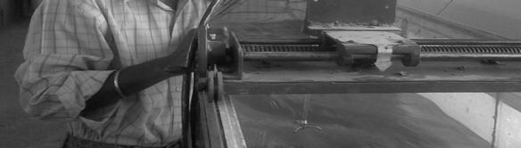
55 Photo Gallery: Plate 1: Front View of ADV Plate 2: Blades of ADV Plate 3: Measuring the velocities


56 Plate 4: A close look at the channels Plate 5: Adjusting the delicate ADV
MEANDERING EFFECT FOR EVALUATION OF ROUGHNESS COEFFICIENTS IN OPEN CHANNEL FLOW
 Conference on Advances in Fluid Mechanics, 5th -7th September 00, Algarve-Portugal MEANDERING EFFECT FOR EVALUATION OF ROUGHNESS COEFFICIENTS IN OPEN CHANNEL FLOW K. K. Khatua, K.C.Patra and P.Nayak Department
STAGE DISCHARGE PREDICTION FOR MEANDERING CHANNELS
 K.K. Khatua, et al., Int. J. Comp. Meth. and Exp. Meas., Vol. 1, No. 1 (2013) 80 92 STAGE DISCHARGE PREDICTION FOR MEANDERING CHANNELS K. K. KHATUA, K.C. PATRA, P. NAYAK & N. SAHOO Department of Civil
APPARENT SHEAR STRESS IN A COMPOUND CHANNEL
 APPARENT SHEAR STRESS IN A COMPOUND CHANNEL K. K. Khatua K. C. Patra R. Jha Asst. Professor Professor Professor Email: kkkhatua@yahoo.com/ kkkhatua@nitrkl.ac.in Department of Civil Engineering, N.I.T.Rourkela,
Transverse Distribution of Shear Stress in Compound Meandering Channel
 e-issn: 2278-1684, p-issn: 232-334X. Transverse Distribution of Shear Stress in Compound Meandering Channel A.sahu 1, L.Mohanty 2, K.K.Khatua³ 1,2 ( Department of Civil Engineering, VSSUT burla, India)
An experimental study of longitudinal velocity distribution at cross-over and bend section of a compound meandering channel
 American Journal of Civil Engineering 2013; 1(3): 124-128 Published online November 20, 2013 (http://www.sciencepublishinggroup.com/j/ajce) doi: 10.11648/j.ajce.20130103.16 An experimental study of longitudinal
Experimental Study of Discharge Characteristics in a Compound Meandering River
 American Journal of Engineering Research (AJER) e-issn : 2320-0847 p-issn : 2320-0936 Volume-02, Issue-07, pp-136-140 www.ajer.org Research Paper Open Access Experimental Study of Discharge Characteristics
ANALYSIS OF FLOW ALONG THE MEANDER PATH OF A HIGHLY SINUOUS RIGID CHANNEL
 ANALYSIS OF FLOW ALONG THE MEANDER PATH OF A HIGHLY SINUOUS RIGID CHANNEL A Thesis Submitted in Partial Fulfilment of the Requirement for the Degree of Master of Technology In Civil Engineering ARPAN PRADHAN
Analysis of Depth Averaged Velocity in Meandering Compound Channels
 Analysis of Depth Averaged Velocity in Meandering Compound Channels Prof. K.C.Patra, Ellora Padhi, Laxmipriya Mohanty & Manaswinee Patnaik. Department of Water Resources Engineering, National Institute
Stage Discharge Prediction in a Prismatic Compound Channel
 International Journal of Civil Engineering Research. ISSN 2278-3652 Volume 5, Number 3 (2014), pp. 227-232 Research India Publications http://www.ripublication.com/ijcer.htm Stage Discharge Prediction
EQUATIONS FOR DISCHARGE CALCULATION IN COMPOUND CHANNELS HAVING HOMOGENEOUS ROUGHNESS * S. M. HOSSEINI **
 Iranian Journal of Science & Technology, Transaction B, Vol. 28, No. B5 Printed in The Islamic Republic of Iran, 2004 Shiraz University EQUATIONS FOR DISCHARGE CALCULATION IN COMPOUND CHANNELS HAVING HOMOGENEOUS
This is a repository copy of Stage-Discharge Prediction for Converging Compound Channels with Narrow Floodplains.
 This is a repository copy of Stage-Discharge Prediction for Converging Compound Channels with Narrow Floodplains. White Rose Research Online URL for this paper: http://eprints.whiterose.ac.uk/126630/ Version:
MEANDERING EFFECT FOR EVALUATION OF ROUGHNESS COEFFICIENTS AND BOUNDARY SHEAR DISTRIBUTION IN OPEN CHANNEL FLOW
 MEANDERING EFFECT FOR EVALUATION OF ROUGHNESS COEFFICIENTS AND BOUNDARY SHEAR DISTRIBUTION IN OPEN CHANNEL FLOW A Thesis Submitted in Partial Fulfillment of the Requirements for the Degree of Master of
Prediction of bed form height in straight and meandering compound channels
 Water Resources Management III 311 Prediction of bed form height in straight and meandering compound channels R. D. Karamisheva, J. F. Lyness, W. R. C. Myers, J. O Sullivan & J. B. C. Cassells School of
APPLICATION OF ADAPTIVE NEURO-FUZZY INFERENCE SYSTEM FOR THE ESTIMATION OF ROUGHNESS COEFFICIENT OF A MEANDERING OPEN-CHANNEL FLOW
 S. Moharana et al., Int. J. Sus. Dev. Plann. Vol. 10, No. 1 (2015) 87 99 APPLICATION OF ADAPTIVE NEURO-FUZZY INFERENCE SYSTEM FOR THE ESTIMATION OF ROUGHNESS COEFFICIENT OF A MEANDERING OPEN-CHANNEL FLOW
Keywords: flow characteristics, compound straight channel, bed morphology, floodplain
 Flow Characteristics on Floodplain Vegetation in Compound Straight Channels Nur Amirah Nabilah Mohd Zamri 1, a, Zulhilmi Ismail 1,b,Zulkiflee Ibrahim 1,c 1 Faculty of Civil Engineering, Universiti Teknologi
Detailed Investigation of Velocity Distributions in Compound Channels for both Main Channel and Flood Plain
 Detailed Investigation of Velocity Distributions in Compound Channels for both Main Channel and Flood Plain Jarmina Nake 1, Dr. Mimi Das Saikia 2 M.Tech Student, Dept. of Civil engineering, ADTU, Guwahati,
VARIATION OF MANNING S ROUGHNESS COEFFICIENT WITH SEEPAGE IN SAND-BED CHANNEL *Satish Patel 1 and Bimlesh Kumar 2
 International Journal of Science, Environment and Technology, Vol. 5, No 6, 2016, 3678 3685 ISSN 2278-3687 (O) 2277-663X (P) VARIATION OF MANNING S ROUGHNESS COEFFICIENT WITH SEEPAGE IN SAND-BED CHANNEL
Influence of Two-line Emergent Floodplain Vegetation on A Straight Compound Channel Flow
 International Journal of Integrated Engineering, Vol. 5 No. 1 (2013) p. 58-63 Influence of Two-line Emergent Floodplain Vegetation on A Straight Compound Channel Flow Mazlin Jumain 1,*, Zulkiflee Ibrahim
Composite roughness for rough compound channels
 Composite roughness for rough compound channels S. Pradhan Research Scholar (Ph. D), Department of Civil Engineering, National Institute of Technology, Rourkela, Orissa, India K.K.Khatua Associate Professor,
Energy and momentum coefficients for wide compound channels
 River Basin Management VII 87 Energy and momentum coefficients for wide compound channels P. K. Mohanty, S. S. Dash, K. K. Khatua & K. C. Patra Department of Civil Engineering, N.I.T. Rourkela, India Abstract
Canadian Journal of Civil Engineering. Gene-Expression Programming to Predict Manning s n in Meandering Flows
 Gene-Expression Programming to Predict Manning s n in Meandering Flows Journal: Canadian Journal of Civil Engineering Manuscript ID cjce-2016-0569.r2 Manuscript Type: Article Date Submitted by the Author:
Laboratory Investigation of Submerged Vane Shapes Effect on River Banks Protection
 Australian Journal of Basic and Applied Sciences, 5(12): 1402-1407, 2011 ISSN 1991-8178 Laboratory Investigation of Submerged Vane Shapes Effect on River Banks Protection Touraj Samimi Behbahan Department
Hydraulics of bendway weirs
 River Basin Management IV 389 Hydraulics of bendway weirs C. Thornton 1, S. Abt 1, D. Baird 2 & R. Padilla 3 1 Colorado State University, Fort Collins, CO, USA 2 U.S. Bureau of Reclamation, Denver, CO,
Flow and Bed Topography in a 180 Curved Channel
 Flow and Bed Topography in a 180 Curved Channel Jae Wook Jung 1, Sei Eui Yoon 2 Abstract The characteristics of flow and bed topography has been analyzed by changing the bed materials in a 180-degree,
Accounting for increased flow resistance due to lateral momentum loss in restoration designs using 2-stage channels
 Skamania 2005 Accounting for increased flow resistance due to lateral momentum loss in restoration designs using 2-stage channels Outline Aim and Objectives Definition Use of 2-stage channels in stream
COMPARISON OF LABORATORY AND FIELD MEASUREMENTS OF BRIDGE PIER SCOUR
 COMPARISON OF LABORATORY AND FIELD MEASUREMENTS OF BRIDGE PIER SCOUR LEE, SEUNGOH, STURM, T. W., School of Civil and Environ. Engrg., Georgia Institute of Technology Atlanta, GA 30332-0512 USA GOTVALD,
VELOCITY DISTRIBUTION IN TRAPEZOIDAL MEANDERING CHANNEL. A thesis submitted to. National Institute of Technology, Rourkela
 VELOCITY DISTRIBUTION IN TRAPEZOIDAL MEANDERING CHANNEL A thesis submitted to National Institute of Technology, Rourkela In partial fulfillment for the award of the degree of Master of Technology in Civil
Free Flow Below Skew Sluice Gate
 International Journal of Engineering Research and Development e-issn: 2278-67X, p-issn: 2278-8X, www.ijerd.com Volume, Issue 3 (March 24), PP.44-52 Talib Mansoor Civil Engineering Department, Aligarh Muslim
Discharge estimation in compound channels with fixed and mobile bed
 Sādhanā Vol. 34, Part 6, December 2009, pp. 923 945. Indian Academy of Sciences Discharge estimation in compound channels with fixed and mobile bed GALIP SECKIN 1, MUSTAFA MAMAK 1, SERTER ATABAY 2 and
THE HYDRAULIC PERFORMANCE OF ORIENTED SPUR DIKE IMPLEMENTATION IN OPEN CHANNEL
 Tenth International Water Technology Conference, IWTC10 2006, Alexandria, Egypt 281 THE HYDRAULIC PERFORMANCE OF ORIENTED SPUR DIKE IMPLEMENTATION IN OPEN CHANNEL Karima Attia 1 and Gamal El Saied 2 1
EFFECT OF BAFFLE BLOCKS ON THE PERFORMANCE OF RADIAL HYDRAULIC JUMP
 Fourth International Water Technology Conference IWTC 99, Alexandria, Egypt 255 EFFECT OF BAFFLE BLOCKS ON THE PERFORMANCE OF RADIAL HYDRAULIC JUMP O. S. Rageh Irrigation & Hydraulics Dept., Faculty of
Investigation of Flow Profile in Open Channels using CFD
 Investigation of Flow Profile in Open Channels using CFD B. K. Gandhi 1, H.K. Verma 2 and Boby Abraham 3 Abstract Accuracy of the efficiency measurement of a hydro-electric generating unit depends on the
Formation Of Hydraulic Jumps On Corrugated Beds
 International Journal of Civil & Environmental Engineering IJCEE-IJENS Vol:10 No:01 37 Formation Of Hydraulic Jumps On Corrugated Beds Ibrahim H. Elsebaie 1 and Shazy Shabayek Abstract A study of the effect
FORMATION OF HYDRAULIC JUMPS ON CORRUGATED BEDS
 International Journal of Civil & Environmental Engineering IJCEE-IJENS Vol: 10 No: 01 40 FORMATION OF HYDRAULIC JUMPS ON CORRUGATED BEDS Ibrahim H. Elsebaie 1 and Shazy Shabayek Abstract A study of the
Abstract. 1 Introduction
 One-dimensional unsteady flow computation in channels with floodplains D. Bousmar, R. Scherer & Y. Zech Civil Engineering Dept., Universite Catholique de Louvain, Place du Levant, 1, B-1348 Louvain-la-Neuve,
FLOOD-FLOW CHARACTERISTICS OF EQUATORIAL NATURAL RIVERS IN SARAWAK, MALAYSIA (Date received: )
") FLOOD-FLOW CHARACTERISTICS OF EQUATORIAL NATURAL RIVERS IN SARAWAK, MALAYSIA (Date received: 24.4.2007) Sai Hin Lai 1, Nabil Bessaih 2, Puong Ling Law 2, Nor Azazi bin Zakaria 1, Aminuddin bin Ghani 1
FLOOD-FLOW CHARACTERISTICS OF EQUATORIAL NATURAL RIVERS IN SARAWAK, MALAYSIA (Date received: 24.4.2007) Sai Hin Lai 1, Nabil Bessaih 2, Puong Ling Law 2, Nor Azazi bin Zakaria 1, Aminuddin bin Ghani 1
Head Discharge Relationship of Thin Plated Rectangular Lab Fabricated Sharp Crested Weirs
 Journal of Applied Fluid Mechanics, Vol. 9, No. 3, pp. 1231-1235, 2016. Available online at www.jafmonline.net, ISSN 1735-3572, EISSN 1735-3645. DOI: 10.18869/acadpub.jafm.68.228.23128 Head Discharge Relationship
1. Introduction. Keywords Compound channel, Momentum transfer, Relative roughness, Relative depth, Relative width
 International Journal of Hydraulic Engineering, (): -8 DOI:.9/j.ijhe.. Investigating the Effect of and Relative Roughness on Momentum Transfer in Symmetric Rectangular Compound Channels with Varius Relative
INFLUENCE OF OFF-TAKE ANGLES ON FLOW DISTRIBUTION PATTERN AT CONCAVE CHANNEL BIFURCATION
 INFLUENCE OF OFF-TAKE ANGLES ON FLOW DISTRIBUTION PATTERN AT CONCAVE CHANNEL BIFURCATION 1 2 2 OBASI, N.L., AGUNWAMBA, J.C. AND EGBUNIWE, N. 1. Department of Civil Engineering, Enugu State University of
Fluid Mechanics Prof. S.K. Som Department of Mechanical Engineering Indian Institute of Technology, Kharagpur
 Fluid Mechanics Prof. S.K. Som Department of Mechanical Engineering Indian Institute of Technology, Kharagpur Lecture - 42 Flows with a Free Surface Part II Good morning. I welcome you to this session
5. Secondary Current and Spiral Flow
 5. Secondary Current and Spiral Flow The curve of constant velocity for rectangular and triangular cross-section obtained by Nikuradse are shown in Figures and 2. In all cases the velocities at the corners
Closed duct flows are full of fluid, have no free surface within, and are driven by a pressure gradient along the duct axis.
 OPEN CHANNEL FLOW Open channel flow is a flow of liquid, basically water in a conduit with a free surface. The open channel flows are driven by gravity alone, and the pressure gradient at the atmospheric
Analysis of Flow Resistance for Different Bed Materials with Varying Discharge Experimentally in Open Channels
 Analysis of Flow Resistance for Different Bed Materials with Varying Discharge Experimentally in Open Channels Lakshmi Mitra 1, Dr.Mimi Das Saikia 2 M.Tech. Student, Department of Civil Engineering, Assam
MEASUREMENT OF 3D FLOW FIELD IN A 90 BEND WITH ULTRASONIC DOPPLER VELOCITY PROFILER
 MEASUREMENT OF 3D FLOW FIELD IN A 90 BEND WITH ULTRASONIC DOPPLER VELOCITY PROFILER Daniel S. Hersberger 1 1 Research associate, Laboratory of Hydraulic Constructions (LCH), Swiss Federal Institute of
THE EFFECT OF THICKNESS OF PILLAR IN THE CHANNEL BEND TO CHANGES THE COEFFICIENT OF SUPERELEVATION
 Journal Engineering Science and Technology Vol. 11, No. 5 (2016) 745-754 School Engineering, Taylor s University THE EFFECT OF THICKNESS OF PILLAR IN THE CHANNEL BEND TO CHANGES THE COEFFICIENT OF SUPERELEVATION
Efficiency of an Expansive Transition in an Open Channel Subcritical Flow
 DUET Journal Vol., Issue, June of an Expansive Transition in an Open Channel Subcritical Flow B. C. Basak and M. Alauddin Department of Civil Engineering Dhaka University of Engineering & Technology, Gazipur,
EFFECT OF CHANNEL BENDS ON TRANSVERSE MIXING
 NIJOTECH VOL. 10. NO. 1 SEPTEMBER 1986 ENGMANN 57 EFFECT OF CHANNEL BENDS ON TRANSVERSE MIXING BY E. O. ENGMANN ABSTRACT Velocity and tracer concentration measurements made in a meandering channel are
Discharge estimation for equatorial natural rivers with overbank flow
 Intl. J. River Basin Management Vol. 6, No. (28), pp. 3 2 28 IAHR, INBO & IAHS Discharge estimation for equatorial natural rivers with overbank flow LAI SAI HIN, Lecturer, River Engineering and Urban Drainage
This is a repository copy of An analytical model for lateral depth-averaged velocity distributions along a meander in curved compound channels.
 This is a repository copy of An analytical model for lateral depth-averaged velocity distributions along a meander in curved compound channels. White Rose Research Online URL for this paper: http://eprints.whiterose.ac.uk/80340/
Prof. B.S. Thandaveswara. Superelevation is defined as the difference in elevation of water surface between inside (1)
") 36.4 Superelevation Superelevation is defined as the difference in elevation of water surface between inside and outside wall of the bend at the same section. y=y y (1) 1 This is similar to the road banking
36.4 Superelevation Superelevation is defined as the difference in elevation of water surface between inside and outside wall of the bend at the same section. y=y y (1) 1 This is similar to the road banking
Hydraulic characteristics of meandering mobile bed compound channels
 Hydraulic characteristics of meandering mobile bed compound channels J. F. Lyness, MSc, PhD, MICE, W.R.C.Myers,BA, BSc, PhD, MICE and J. J. O'Sullivan, BA, BAI, MSc Proc. Instn Civ. Engrs Wat., Marit.
STUDY OF BOUNDARY LAYER PARAMETERS ON A FLAT PLATE USING WIND TUNNEL
 . STUDY OF BOUNDARY LAYER PARAMETERS ON A FLAT PLATE USING WIND TUNNEL A REPORT SUBMITTED IN PARTIAL FULFILLMENT OF THE REQUIREMENTS FOR THE DEGREE OF Bachelor of Technology In Civil Engineering By GYANARANJAN
Conveyance Estimation System (CES) Launch
 Launch") (CES) Launch Conveyance Principles Caroline McGahey 10 June 2004 Why is there a new approach? Existing 1D software still based on historic hand-calculation methods - not based in rigorous physics - as
(CES) Launch Conveyance Principles Caroline McGahey 10 June 2004 Why is there a new approach? Existing 1D software still based on historic hand-calculation methods - not based in rigorous physics - as
Design of Stilling Basins using Artificial Roughness
 Design of Stilling Basins using Artificial Roughness N. AboulAtta 1, G. Ezizah 2, N. Yousif 3, S. Fathy 4 Abstract The stilling basins are commonly used to dissipate the energy and protect the downstream
Geomorphology Geology 450/750 Spring Fluvial Processes Project Analysis of Redwood Creek Field Data Due Wednesday, May 26
 Geomorphology Geology 450/750 Spring 2004 Fluvial Processes Project Analysis of Redwood Creek Field Data Due Wednesday, May 26 This exercise is intended to give you experience using field data you collected
FE Fluids Review March 23, 2012 Steve Burian (Civil & Environmental Engineering)
") Topic: Fluid Properties 1. If 6 m 3 of oil weighs 47 kn, calculate its specific weight, density, and specific gravity. 2. 10.0 L of an incompressible liquid exert a force of 20 N at the earth s surface.
Topic: Fluid Properties 1. If 6 m 3 of oil weighs 47 kn, calculate its specific weight, density, and specific gravity. 2. 10.0 L of an incompressible liquid exert a force of 20 N at the earth s surface.
Factors affecting confluence scour
 & Wang (eds) River Sedimentation 1999., Balkema, Rotterdam. ISBN 9 9 3. 17 19 Factors affecting confluence scour R. B. Rezaur & A. W. Jayawardena. Department of Civil Engineering, The University of Hong
Lecture 10: River Channels
 GEOG415 Lecture 10: River Channels 10-1 Importance of channel characteristics Prediction of flow was the sole purpose of hydrology, and still is a very important aspect of hydrology. - Water balance gives
Kinetic energy and momentum correction factors in a stream
 Kinetic energy and momentum correction factors in a stream Mehmet Ardıçlıoğlu, Mücella Vapur, 2Onur Genç, University of Erciyes, Department of Civil Engineering, Kayseri, Turkey 2 Melikşah University,
PRESSURE AND SCOURING AROUND A SPUR DIKE DURING THE SURGE PASS
 Annual Journal of Hydraulic Engineering, JSCE, Vol.3, 3, February PRESSURE AND SCOURING AROUND A SPUR DIKE DURING THE SURGE PASS Tomasz MIODUSZEWSKI and Shiro MAENO Student Member of JSCE, Doctoral Student,
Application of an ultrasonic velocity profile monitor in a hydraulic laboratory
 Application of an ultrasonic velocity profile monitor in a hydraulic laboratory Abstract Helmut Knoblauch 1, Roman Klasinc 1, Thomas Geisler 1 Velocity profile measurement using the ultrasound-pulse-doppler
EXPERIMENTAL STUDY OF FLOW THROUGH RIGID VEGETATION IN OPEN CHANNEL
 EXPERIMENTAL STUDY OF FLOW THROUGH RIGID VEGETATION IN OPEN CHANNEL A Thesis Submitted in Partial Fulfilment of the Requirements for the Degree of Master of Technology in Civil Engineering KAJAL PANIGRAHI
INSTITUTE OF AERONAUTICAL ENGINEERING Dundigal, Hyderabad AERONAUTICAL ENGINEERING QUESTION BANK : AERONAUTICAL ENGINEERING.
 Course Name Course Code Class Branch INSTITUTE OF AERONAUTICAL ENGINEERING Dundigal, Hyderabad - 00 0 AERONAUTICAL ENGINEERING : Mechanics of Fluids : A00 : II-I- B. Tech Year : 0 0 Course Coordinator
Spreadsheet Tools for Quantifying the Costs and Benefits of Two-Stage Channels
 Spreadsheet Tools for Quantifying the Costs and Benefits of Two-Stage Channels J. Witter, A. Ward, D. Mecklenburg, J. D Ambrosio, S. Roley, and J. Tank AWRA Agricultural Hydrology and Water Quality II
Closed duct flows are full of fluid, have no free surface within, and are driven by a pressure gradient along the duct axis.
 OPEN CHANNEL FLOW Open channel flow is a flow of liquid, basically water in a conduit with a free surface. The open channel flows are driven by gravity alone, and the pressure gradient at the atmospheric
MAHATMA GANDHI MISSION S JAWAHARLAL NEHRU ENGINEERING COLLEGE, FLUID MECHANICS LABORATORY MANUAL
 MAHATMA GANDHI MISSION S JAWAHARLAL NEHRU ENGINEERING COLLEGE, AURANGABAD. (M.S.) DEPARTMENT OF CIVIL ENGINEERING FLUID MECHANICS LABORATORY MANUAL Prepared By Mr. L. K. Kokate Lab Incharge Approved By
CHAPTER 2- BACKGROUND. INVESTIGATIONS OF COMPOSITE ROUGHNESS COEFFICIENT IN A RIVER WITH LOW FLOW
 2. Background 2.1 Introduction The estimation of resistant coefficient and hence discharge capacity in a channel or river is one of the fundamental problems facing river engineers. When applying Manning
Analysis of flow around impermeable groynes on one side of symmetrical compound channel: An experimental study
 Water Science and Engineering, 2010, 3(1): 56-66 doi:10.3882/j.issn.1674-2370.2010.01.006 http://www.waterjournal.cn e-mail: wse2008@vip.163.com Analysis of flow around impermeable groynes on one side
MATHEMATICAL MODELING OF FLUVIAL SEDIMENT DELIVERY, NEKA RIVER, IRAN. S.E. Kermani H. Golmaee M.Z. Ahmadi
 JOURNAL OF ENVIRONMENTAL HYDROLOGY The Electronic Journal of the International Association for Environmental Hydrology On the World Wide Web at http://www.hydroweb.com VOLUME 16 2008 MATHEMATICAL MODELING
ECM PROCESS CHARACTERISTICS
 ECM PROCESS CHARACTERISTICS A PROJECT SUBMITTED IN PARTIAL FULFILLMENT OF THE REQUIREMENT FOR THE DEGREE OF Bachelor of Technology In Mechanical Engineering Submitted by: ANIL KUMAR MEHER ROLL NO. : 10503046
Transactions on Engineering Sciences vol 9, 1996 WIT Press, ISSN
 A study of turbulence characteristics in open channel transitions as a function of Froude and Reynolds numbers using Laser technique M.I.A. El-shewey, S.G. Joshi Department of Civil Engineering, Indian
R09. d water surface. Prove that the depth of pressure is equal to p +.
 Code No:A109210105 R09 SET-1 B.Tech II Year - I Semester Examinations, December 2011 FLUID MECHANICS (CIVIL ENGINEERING) Time: 3 hours Max. Marks: 75 Answer any five questions All questions carry equal
INTERRELATIONSHIP BETWEEN RIVER SEDIMENTATION AND MEANDERING: A CASE STUDY OF GANGA AT VARANASI
 INTERRELATIONSHIP BETWEEN RIVER SEDIMENTATION AND MEANDERING: A CASE STUDY OF GANGA AT VARANASI Anoop Nr. Singh *1, A.K.Upadhyay 2, U.K. Choudhary 3, J.P.Sonkar 4 1. Research Scholar, Department of Civil
Local Scouring due to Flow Jet at Downstream of Rectangular Sharp-Crested Weirs
 Local Scouring due to Flow Jet at Downstream of Rectangular Sharp-Crested Weirs DEHGHANI, AMIR. AHMAD 1, BASHIRI, HAMID and MESHKATI SHAHMIRZADI, MOHAMMAD. EBRAHIM 3 1,3 Dept. of Water Engineering, Gorgan
Applying GIS to Hydraulic Analysis
 Texas A&M University Department of Civil Engineering CVEN689 Applications of GIS to Civil Engineering Instructor: Francisco Olivera, Ph.D., P.E. Applying GIS to Hydraulic Analysis Lim, Chae Kwan April
Flood Capacity of Shirakawa River at Tatsudajinnnai Area in Kumamoto Prefecture
 International Journal of Economy, Energy and Environment 218; 3(5): 51-57 http://www.sciencepublishinggroup.com/j/ijeee doi: 1.11648/j.ijeee.21835.13 ISSN: 2575-513 (Print); ISSN: 2575-521 (Online) Flood
Lab #4 Similitude: The Kármán Vortex Street CEE 331 Fall 2004
 CEE 331 Lab 4 Page 1 of 6 Lab #4 Similitude: The Kármán Vortex Street CEE 331 Fall 2004 Safety The major safety hazard in this laboratory is a shock hazard. Given that you will be working with water and
DEVELOPED LAMINAR FLOW IN PIPE USING COMPUTATIONAL FLUID DYNAMICS M.
 DEVELOPED LAMINAR FLOW IN PIPE USING COMPUTATIONAL FLUID DYNAMICS M. Sahu 1, Kishanjit Kumar Khatua and Kanhu Charan Patra 3, T. Naik 4 1, &3 Department of Civil Engineering, National Institute of technology,
International Journal of Advance Research, IJOAR.org ISSN
 International Journal of Advance Research, IJOAR.org 1 International Journal of Advance Research, IJOAR.org Volume 1, Issue 9, September 2013, Online: Coefficient Of Discharge For A Compound Weir Combined
Predictions on arrival times of water of the St. Francis dam break flood using ANUGA
 20th International Congress on Modelling and Simulation, Adelaide, Australia, 1 6 December 2013 www.mssanz.org.au/modsim2013 Predictions on arrival times of water of the St. Francis dam break flood using
53:071 Principles of Hydraulics Laboratory Experiment #3 ANALYSIS OF OPEN-CHANNEL FLOW TRANSITIONS USING THE SPECIFIC ENERGY DIAGRAM
 53:071 Principles of Hydraulics Laboratory Experiment #3 ANALYSIS OF OPEN-CHANNEL FLOW TRANSITIONS USING THE SPECIFIC ENERGY DIAGRAM Principle Adaptation of the Bernoulli equation to open-channel flows
New computation method for flood flows and bed variations in a low-lying river with complex river systems
 River Flow 2014 Schleiss et al. (Eds) 2014 Taylor & Francis Group, London, ISBN 978-1-138-02674-2 New computation method for flood flows and bed variations in a low-lying river with complex river systems
P10.5 Water flows down a rectangular channel that is 4 ft wide and 3 ft deep. The flow rate is 15,000 gal/min. Estimate the Froude number of the flow.
 P10.5 Water flows down a rectangular channel that is 4 ft wide and ft deep. The flow rate is 15,000 gal/min. Estimate the Froude number of the flow. Solution: Convert the flow rate from 15,000 gal/min
The Effect of Bedform-induced Spatial Acceleration on Turbulence and Sediment Transport
 The Effect of Bedform-induced Spatial Acceleration on Turbulence and Sediment Transport S. McLean (1) (1) Mechanical and Environmental Engineering Dept., University of California, Santa Barbara, CA 93106,
Experiment (4): Flow measurement
: Flow measurement") Experiment (4): Flow measurement Introduction: The flow measuring apparatus is used to familiarize the students with typical methods of flow measurement of an incompressible fluid and, at the same time
Experiment (4): Flow measurement Introduction: The flow measuring apparatus is used to familiarize the students with typical methods of flow measurement of an incompressible fluid and, at the same time
Lecture Note for Open Channel Hydraulics
 Chapter -one Introduction to Open Channel Hydraulics 1.1 Definitions Simply stated, Open channel flow is a flow of liquid in a conduit with free space. Open channel flow is particularly applied to understand
Channel Pattern. Channel Pattern, Meanders, and Confluences. Description of Channel Pattern. Bridge (2003)
") Channel Pattern Channel Pattern, Meanders, and Confluences Outline Description of channel pattern Alternate bars Channel pattern continua and evolution Controls of channel pattern Description of Channel
Channel Pattern Channel Pattern, Meanders, and Confluences Outline Description of channel pattern Alternate bars Channel pattern continua and evolution Controls of channel pattern Description of Channel
PERFORMANCE OF A CENTRAL-TYPE JET PUMP II- EXPERIMENTAL STUDY ON WATER FLOW
 Eighth International Water Technology Conference, IWTC8 24, Alexandria, Egypt PERFORMANCE OF A CENTRAL-TYPE JET PUMP II- EXPERIMENTAL STUDY ON WATER FLOW ABSTRACT EL-Otla, F. M. *, EL-Sawaf, I. A. * and
A note on critical flow section in collector channels
 Sādhan ā, Vol. 26, Part 5, October 2001, pp. 439 445. Printed in India A note on critical flow section in collector channels 1. Introduction SUBHASISH DEY Department of Civil Engineering, Indian Institute
Measurements of Turbulent Pressure Under Breaking Waves
 MEASUREMENTS OF TURBULENT PRESSURE UNDER BREAKING WAVES 33 Measurements of Turbulent Pressure Under Breaking Waves Author: Faculty Sponsor: Department: Christopher Olsen Francis Ting, Ph.D., P.E. Civil
A Computational Fluid Dynamics Investigation of Solar Air Heater Duct Provided with Inclined Circular Ribs as Artificial Roughness
 Bonfring International Journal of Industrial Engineering and Management Science, Vol. 4, No. 3, August 2014 115 A Computational Fluid Dynamics Investigation of Solar Air Heater Duct Provided with Inclined
Hydraulics for Urban Storm Drainage
 Urban Hydraulics Hydraulics for Urban Storm Drainage Learning objectives: understanding of basic concepts of fluid flow and how to analyze conduit flows, free surface flows. to analyze, hydrostatic pressure
Open Channel Flow Part 2. Ch 10 Young, notes, handouts
 Open Channel Flow Part 2 Ch 10 Young, notes, handouts Uniform Channel Flow Many situations have a good approximation d(v,y,q)/dx=0 Uniform flow Look at extended Bernoulli equation Friction slope exactly
EXPERIMENTAL AND NUMERICAL STUDIES OF A SPIRAL PLATE HEAT EXCHANGER
 THERMAL SCIENCE: Year 2014, Vol. 18, No. 4, pp. 1355-1360 1355 EXPERIMENTAL AND NUMERICAL STUDIES OF A SPIRAL PLATE HEAT EXCHANGER by Rangasamy RAJAVEL Department of Mechanical Engineering, AMET University,
Hydraulics. B.E. (Civil), Year/Part: II/II. Tutorial solutions: Pipe flow. Tutorial 1
, Year/Part: II/II. Tutorial solutions: Pipe flow. Tutorial 1") Hydraulics B.E. (Civil), Year/Part: II/II Tutorial solutions: Pipe flow Tutorial 1 -by Dr. K.N. Dulal Laminar flow 1. A pipe 200mm in diameter and 20km long conveys oil of density 900 kg/m 3 and viscosity
Hydraulics B.E. (Civil), Year/Part: II/II Tutorial solutions: Pipe flow Tutorial 1 -by Dr. K.N. Dulal Laminar flow 1. A pipe 200mm in diameter and 20km long conveys oil of density 900 kg/m 3 and viscosity
We will assume straight channels with simple geometries (prismatic channels) and steady state flow (in time).
 and steady state flow (in time).") 56 Review Drag & Lift Laminar vs Turbulent Boundary Layer Turbulent boundary layers stay attached to bodies longer Narrower wake! Lower pressure drag! 8. Open-Channel Flow Pipe/duct flow closed, full,
56 Review Drag & Lift Laminar vs Turbulent Boundary Layer Turbulent boundary layers stay attached to bodies longer Narrower wake! Lower pressure drag! 8. Open-Channel Flow Pipe/duct flow closed, full,
Storm Water Best Management Practice: Development of Debris Filtering Structure for Supercritical Flow
 Storm Water Best Management Practice: Development of Debris Filtering Structure for Supercritical Flow Jungseok Ho 1, Todd Marti 2, and Julie Coonrod 3 1 Department of Civil Engineering, University of
Experimentally determined distribution of granular-flow characteristics in collisional bed load transport
 Experimentally determined distribution of granular-flow characteristics in collisional bed load transport Václav Matoušek 1,*, Štěpán Zrostlík 1, Luigi Fraccarollo 2, Anna Prati 2, and Michele Larcher
FLOW IN CONDUITS. Shear stress distribution across a pipe section. Chapter 10
 Chapter 10 Shear stress distribution across a pipe section FLOW IN CONDUITS For steady, uniform flow, the momentum balance in s for the fluid cylinder yields Fluid Mechanics, Spring Term 2010 Velocity
Advanced Hydraulics Prof. Dr. Suresh A Kartha Department of Civil Engineering Indian Institute of Technology, Guwahati
 Advanced Hydraulics Prof. Dr. Suresh A Kartha Department of Civil Engineering Indian Institute of Technology, Guwahati Module - 2 Uniform Flows Lecture - 6 Design of Channels for Uniform Flow (Refer Slide