Soil Mechanics I CE317
|
|
|
- Rosamond Norris
- 5 years ago
- Views:
Transcription
1 Soil Mechanics I CE317 Civil Engineering Department/ Third Stage Semester (Fall ) 1
2 Course Name: Soil Mechanics I Code: CE317 Name of Lecturer Office No.: Room # 217, 1 st floor Classroom and Meeting Time: Room #308, Sunday/ Group A (9:00-10:50 a.m.), Room #308, Sunday/ Group B (11:00-12:50 a.m.), Room #124 (soil Lab.), two hours per week for each group divided according to the time table. Number of Hours: Two hours per week for theory and another two per week for laboratory. Course Description: This class presents the principles of soil mechanics. It considers the following topics: the origin and nature of soils; volume-weight relations, soil consistency, soil classification, the total and effective stresses, hydraulic conductivity and seepage, compaction, and laboratory methods used to evaluate soil properties. Course Outcomes: Students who successfully complete this course will be able to: 1- Apply basic mathematics, science and engineering principles to solve engineering problems. 2- Classify soil type according to its engineering properties. 3- Understand the basic phase relations of soil. 4- A close understanding of the special behavior of fine grained soil through studying its states limits ( liquid limit, Plastic limit and Shrinkage limit ), and/or its indices (Plasticity index, liquidity index ) 5- Can calculate the earth overburden pressure. 6- Perform common soil tests to identify physical and mechanical properties of soils. 7- Be familiar with soil mechanics tests and determines which test is needed in designing civil engineering projects and/or solving engineering problems. 8- Demonstrate the ability to write clear technical laboratory reports. 9- Demonstrate the ability to work in groups and understand and apply ethical issues associated with decision making and professional conduct in the lab and field environment. Coarse Contents: 1- Introduction. 2- Soil formation and composition, description of individual soil particles, clay minerals. 3- The physical state of a soil sample (Volume-Weight Relations) 4- Soil consistency 5- Soil classification 6- Definitions of (Clay thixotropy, Types of samples, Soil sensitivity, Over consolidation ratio) 7- Stresses within soil mass and capillarity. 8- Fluid flow in soils: one dimensional flow. 9- Compaction. 2
3 References: 1- Das, B.M., Principle of Geotechnical Engineering, 5th edition. 2- Arora, K. R., Soil Mechanics and Foundation Engineering, 6 th edition. 3- Craig, R.F., Craig s Soil Mechanics, 7 th edition. Course Evaluation Criteria: Method Percentage Attendance 5 Quizzes 15 Laboratory Reports 10 Midterm Examination 30 Final Examination 40 Regulations and Requirements: 1- The passing percent of attendance is 80 from the total coarse hours; if the absence exceeded 20% then the student will not be able to perform the final examination. The student must attend in the time specified for the course, any delay will be considered as absence. 2- The student required to bring to the class: Soil Mechanics lecture notes, scientific calculator (mobile phones are not allowed to use). 3- Homework will be given at the end of the lecture. Submitting the homework must be done at the start of the next lecture of this course. The lecturer will not accept any delay in submitting the homework for any reason. 4- The student must be ready for a quiz about the subjects of previous lectures at any time during the course hours. 5- Participation in the class and paying attention during the lecture are important for collecting extra credits and the reverse is also true, disturbing the lecture will have its consequences on the student. The engineering profession is highly regarded by the public because those who practice it do so with ethical and social consciousness. The same is expected of students in this course. 6- Students are required to keep and assemble in a suitable folder the following : Quiz papers Tests question sheets Laboratory Experiment Reports Lecture notes and class notes 7- Keep all the lecture notes after the end of the semester because it is related to the course (Soil Mechanics II CE322) in the second semester. 3
4 1.1: Definition of Soil Mechanics Chapter One: Introduction Soil mechanics is the science that applies laws and principles of physics especially continuous and particulate mechanics and hydraulics of porous media to solve problems encountered in civil engineering related to force-deformation behavior of soil and the flow of fluids through soil. Or: Soil mechanics is the science dealing with the behavior of soil in engineering practice or how does a soil mass behave when acted on by external forces. Geotechnical Engineering can be defined The branch of Civil engineering that deals with the properties of soils and rocks and their capability of supporting structures placed on or under them. 1.2: Historical Background The properties and behavior of soils have exercised the minds of builders from time immoral. The very little attempt appears to have been made to deal with soil problems on a scientific basis until towards the end of the eighteenth century, when Coulomb published his theory of earth pressure and suggested his well-known law of failure of soils. Rankine s theory followed about a century later, and these two classical theories still form the basis underlying modern methods of estimating earth pressure. However, it was Karl Terzaghi ( ) who first brought theory and empiricism together. By his researches and consulting work, Terzaghi has, with justification, earned the title of The Father of Soil Mechanics 1.3: What Makes Soil Mechanics Interesting and Challenging? Soil stands amongst most variable and difficult of all materials to understand and model. Difficulties arise when one attempts to predict the behavior of soil based on a mathematical model such as: 1-The material we are dealing with may be as weak as soft clay or as strong as hard clay or clay shale. 2- Soil properties vary in both the horizontal and vertical directions and it can be change with time, stress, and environment. 4
5 3- Every site has different soil conditions. We cannot specify in advance the material properties that must be used for construction. 4- Soil "hidden" underground and data on small fraction of deposit. 1.4: Areas Involving the Application of Soil Mechanics 1- Foundation design and selection. - Foundations "shallow" e.g., spread footings for buildings - "deep" e.g., piles for offshore platform. 2- Slopes and Excavations. -Cut slopes for highway -Excavation for subway 3- Retaining Structures. - Slurry wall with tieback anchors -Gravity retaining wall 4- Earth Structures and Embankments -Compacted earth fill for dam -Landfill for waste storage 5- Erosion Control. 6- Seepage under, through and into structures. 7- Waste Disposal System. Chapter Two: Soil Formation and Composition 2.1: Formation and Nature of Soils Soil is any uncemented or weakly cemented accumulation of mineral particles formed by weathering of rocks, the void spaces between particles contains water and/or air. The weak cementation can be due to due to carbonates or oxides precipitated between the particles or due to organic matters. 5
 4- Activity of plants and animals including man Particles formed by in this type of weathering will retain the same")

6 A. Physical or Mechanical weathering causes disintegration of the rocks into smaller particle sizes, the processes that cause physical weathering are: 1- Freezing and thawing 2- Temperature changes 3- Erosion (Abrasion) 4- Activity of plants and animals including man Particles formed by in this type of weathering will retain the same properties as that of parent rock. The shape of soil particles will be approximately equidimensional: angular, sub-angular, and rounded. Each particles being in direct contact with adjoining particles. The structure of the resulting soil might be loose, medium, or dense depending on the way in which the particles are packed together. 6
7 B. Chemical weathering causes decomposition in rocks by: 1- Oxidation : union of oxygen with minerals in rocks forming another minerals 2- Hydration water will enter the crystalline structure of minerals forming another group of minerals 3- Hydrolysis the release Hydrogen from water will union with minerals forming another minerals 4- Carbonation when Co2 is available with the existence of water the minerals changed to Carbonates. Chemical weathering leads to the formation of groups of crystalline particles of collided size (less than 0.002mm) known as the clay minerals. There are two types of soil caused by the effect of erosion: 1- Sedimentary Soils: a- Residual Soils: Material formed by disintegration of underlying parent rock or partially indurated material. It will form Sand (which considered to be favorable foundation conditions), and Clay. Variable properties requiring detailed investigation. Deposits present favorable foundation conditions except in humid and tropical climates. b- Organic Soils: Accumulation of highly organic material formed in place by the growth and subsequent decay of plant life. It is very compressible, entirely unsuitable for supporting building foundations. organic soils can be: i- Peat: A somewhat fibrous aggregate of decayed and decaying vegetation matter having a dark color and odor of decay. ii- Muck: Peat deposits which have advanced in stage of decomposition to such extent that the botanical character is no longer evident. 2- Transported Soils: It constitutes when the products of weathering don t remain at their original location. During the transportation the size and shape of particles can undergo changes and sorted into certain size range. The agents of transportation are: 1- Gravity. 2- Wind. 3- Water. 4- Glaciers. Types of transported soil: A- Alluvial Soils: Material transported and deposited by running water. B- Aeolian Soils: Material transported and deposited by wind. C- Glacial soils: Material transported and deposited by glaciers, or by melt water from the glacier. 7
8 D- Marine Soils: Material transported and deposited by ocean waves and currents in shore and offshore areas. 2.2: Special Soils (problematic soil) 1- Expansive Soils: Expansive soils are distinguished by their potential for great volume increase upon access to moisture. Soils exhibiting such behavior are mostly Montmorillonite clays and clay shales. Expansive soils can be identified by either their plasticity limit or a swell test. 2- Collapsing Soils: Collapsing soils are distinguished by their potential to undergo large decrease in volume upon increase in moisture content even without increase in external loads. Examples: Loess (sugar clay), weakly cemented sands and silts where cementing agent is soluble (e.g., soluble gypsum, halite, etc.), certain granite residual soils, deposits of collapsible soils are usually associated with regions of moisture deficiency. 3- Permafrost and Frost Penetration: Volume Increase from underground ice formation leads to heave of structure. Silts are the most susceptible to frost heave. 4- Man-made and Hydraulic Fills: Found in coastal facilities, levees, dikes and tailings dams, it has high void ratio, subject to large amount of settlement, uniform gradation but variable grain size within same fills, high liquefaction potential, lateral spreading, and can be easily eroded. 5- Limestone and Related Soils: such as Karst Topography and Calcareous Soils. Limestone is very soluble, and the expansion of underground voids can lead to sinkholes. It can originate from biological processes such as sedimentation of skeletal debris and coral reef formation. Limestone can be found in north of Iraq area. 6- Quick Clays: Quick clays are characterized by their great sensitivity or strength reduction upon disturbance. All quick clays are of marine origin. Because of their brittle nature, collapse occurs at relatively small strains. Slopes in quick clays can fail without large movements. 7- Dispersive Clays: Easily eroded by low water velocities, When placed into embankments, tunnels and gullies easily form (piping). Can be dealt with chemical treatment of the soil, use of geotextiles or blockage using different types of walls. 8- Submarine Soils Found in continental shelf deposits at water depths up to several hundred feet. 8
: It Can be determined by sieve analysis and hydrometer test.")
9 2.3: Description of Individual Soil Particles A sample of soil consists of an assemblage of many individual soil particles with air and/or water filling the voids among the particles. The physical properties of the soil can be described by using the following categories: 1- Particle Size (Grain Size): It Can be determined by sieve analysis and hydrometer test. Boulder > 300mm Cobble 150mm to 300mm Gravel 2.0mm to 150mm Sand 0.06mm to 2.0mm Silt 0.002mm to 0.06mm Clay < mm 2-Particle Shape: Equidimentional, disk, sphere, plate, and rod 3- Degree of Roundness or Angularity The degree of roundness refers to the sharpness of the edges and corners of particles. Angular particle soils generally exhibit better engineering properties. 1-Angular 2-Sub-Angular 3-Rounded 4-Well rounded 5-Flanky particles 6-Needle like particles 9
10 4- Surface Texture: -dull or polished -smooth or rough 5-Color: Color is a useful particle character to the geologists, those how works in mining. There are standard cards that specify each type of soil. Soil Cohesion: Cohesionless Soils Generally are granular or coarse grained Particles do not naturally adhere to each other Have higher permeability Cohesive Soils Generally are fine grained Particles have natural adhesion to each other due to presence of clay minerals Have low permeability Coarse-grained, Granular or Cohesionless Soils: Excellent foundation material for supporting structures and roads. The best embankment material. The best backfill material for retaining walls. Might settle under vibratory loads or blasts. Dewatering can be difficult due to high permeability. If free draining not frost susceptible Fine-Grained or Cohesive Soils: Very often, possess low shear strength. Plastic and compressible. Loses part of shear strength upon wetting. Loses part of shear strength upon disturbance. Shrinks upon drying and expands upon wetting. Very poor material for backfill. Poor material for embankments. Practically impervious. 10
11 Clay slopes are prone to landslides. Silts: Characteristics: - Relatively low shear strength - High Capillarity and frost susceptibility - Relatively low permeability -Difficult to compact Compared to Clays: -Better load sustaining qualities - Less compressible - More permeable - Exhibit less volume change 2.4: Clay Minerals Particles Clay minerals are very tiny crystalline substances evolved primarily from chemical weathering of certain rock forming minerals; they are complex alumina silicates plus other metallic ions. All clay minerals are very small with colloidal sized (D < 1 m). Because of their small size and flat shape, they have very large specific surfaces (high surface area to mass ratio). There is usually a negative electric charge on the crystal surfaces and electro chemical forces on these surfaces are therefore predominant in determining their engineering properties. In order to understand why these materials behave as they do, it will be necessary to examine their crystal structure in some detail. The basic structure units of the most clay minerals consist of silica tetrahedron, alumina octahedron Silica tetrahedron 11
12 Alumina octahedron The various clay minerals are formed by the stacking of combination of the basic sheet structures with different forms of bonding between the combined sheets. Clay minerals tend to form flat, plate like shape. Types of Clay Minerals a) Kaolinite: The combined silica-alumina sheets are hold together fairly tightly by Hydrogen bonding. b) Illite: The combined sheets are linked together by fairly weak bonding due to Potassium Ions held between them. 12
13 c) Montmorilonite: The space between the combined sheets is occupied by water ( H 2 O). Properties of montmorilonite: 1-weak bonding. 2- Considerable swelling due to additional water being adsorbed between the combined sheets. 13
, partially saturated (solid + air + water, fully saturated (solid + water)).")
14 2.5: A preview of Soil Behavior The sandy soil composed of deserted particles; the particles are not strongly bounded together so it is free to move. Thus soil is considered as a particulate system, and soil is a multiphase nature (dry (solid + air), partially saturated (solid + air + water, fully saturated (solid + water)). Soil Deformation Nature: The deformation that occur in soil mass, results from an accumulation of several forces acting on the soil particles which causes a compression pressure on the particles that will move above each other to decreasing the voids, which eventually will lead to deform the contact surface of the soil particles, and changing the particle shape as well. The load applied on a soil mass has two components: (N) Normal force and (T) tangential force. 14

15 1- Deformations in Dry Soil: a. Deformation due to contact b. Bending of plate-like particles. c. Inter-particle sliding *the stress-strain behavior of soil will be strongly nonlinear and irreversible. 2- Chemical Interaction: Since the soil is a multiphase system consisting of a mineral phase called the mineral skeleton, plus a fluid phase called the pore fluid, so the quantity of fluid effect on the shear resistance between the soil particles. 15
16 3- Physical Interaction: In saturated soil, the pores are filled with water therefore sustain a pressure on the particles called (pore pressure) Hydrostatic pressure: The pressure in the pore water, at any point equals to the unit weight of water times the depth of the point below the water surface and there is no flow of water. Since the soil is permeable thus the water can flow through soil and interact with mineral skeleton, altering the magnitude of force at the contacts between particles and influencing the compression and shear resistance of the soil. Sharing the load: When load is applied to a soil, it ll have sudden changes, these changes are carried jointly by pore fluid and by the mineral skeleton, the change in pore pressure will cause water to move through the soil, hence the properties of the soil will change with time (Consolidation Settlement) 16

17 Soil Structure: the way the soil particles arrange themselves has an effect on the shear strength, compressibility and permeability of soils. Factors that affect the soil structure are: 1- The shape, size, and mineralogical composition of soil particles, 2- The nature and composition of soil water. Structures in Cohesionless Soil The structures generally encountered in cohesionless soils can be divided into two major categories:- 1. Single grained structure 2. Honeycombed structure In this structure, relatively fine sand and silt form small arches with chains of particles as shown in the figure below. Soils exhibiting honeycombed structure have large void ratios and they can carry ordinary static load. However, under heavy load or when subjected to shock loading, the structure breaks down, resulting in large settlement. 17
18 Structures in Cohesive Soils 1. Dispersed structure 2. Flocculated structure 18
. 3.")
19 Chapter Three: The physical state of a soil sample (Volume-Weight Relations) Since the soil is a multiphase system, the physical and engineering properties of soil spends on the percentage of each element (solid, gas and water). 3.1: Phase Diagram Assumptions and Definitions: - Weight of air W a = 0 -In a dry Soil: Water weight and volume = 0, W w =0, V w =0 - Volume of voids V v include all non-soil volume, both air and water. - In a Saturated Soil: Air volume V a = 0 - Only water and solids appear in completely saturated soil 3.2: Basic Formulas 1) Total volume (V) = V a + V w +V s 2) Total weight (W) = W w + W s 3) Unit weight of water (γ w ) = γ w =9.81 kn/m 3 γ w =1 g /cm 3 γ w = 1000 kg/m 3 γ w = 62.4 lb/ft 3 19
20 4) Total unit weight (γ t ) = units (kn/m 3, kg/m 3, g/cm 3, etc) 5) Unit weight of soil solids (γ s ) = units (kn/m3, kg/m3, g/cm3, etc) 6) Dry unit weight (γ d ) = units (kn/m 3, kg/m 3, g/cm 3, etc) 7) Saturated Unit Weight (γ sat ) = = 8) Submerged unit weight (buoyant unit weight) (effective unit weight) (γ b ) or ( γ ) = γ sat - γ w 9) Specific gravity of soil solids (G s ): is the ratio of soil solids unit weight to the unit weight of distilled water. (unit less) G s = Typical Specific Gravities for Soil Solids Soil Type G s Quartz Sand Silt Clay Chalk Loess Peat Except for organic soils, range is fairly narrow 10) Total specific gravity (G t ) = 11) Porosity (n): the percent of void volume to total volume. n= x 100% 12) Void Ratio (e): the ratio of voids volume to solids volume e = 13) Degree of Saturation (S): The percentage of void volume which is filled with water. S= x 100% When S=100% (Saturated Soil) S=0 (Dry Soil) 100 > S > 0 (Partially Saturated Soil) 14) Moisture Content (Water content) (ω): the weight percentage of water to soil solids 20
21 ω= x 100% 3.3: Mathematical Relations Note: in these rules, every percent should be changed to ratio (divided by 100) before using it. e. S = G s. ω γ t = γ w = G s γ w γ d = = γ b = γ w e = *Try to prove all of the aforementioned mathematical relations. Example (1): A container of soil has a weight of 168 g. On drying the weight became 142 g, the specific gravity of the sand is 2.65, and the volume of the container is 90 cm 3. Find the water content, dry unit weight, total unit weight, voids ratio and porosity. 21
22 Example (2): A sample of soil has, total unit weight of 1.94 g/cm 3, specific gravity of soil solids = 2.65 and void ratio of 0.6. a) Find the moisture content and degree of saturation b) If the degree of saturation became 95% at the same void ratio, then find the total unit weight of soil. Example (3): For a submerged soil sample, the submerged unit weight was 1.08 g/cm 3 and the specific gravity of solids were If the soil sample shrink during drying with 2/3 of its volume. Find the weight of 1.5 m 3 of the dry soil. 22
23 Example (4): prove that ɣ= (in such proves you must start from the left hand side, and with the original rule) 3.4: Density of Cohesionless Soil (granular soils) The natural density of cohesionless soil is conveniently compared with its loose and dense state in terms of voids ratio, this comparison or relative compactness is expressed by the form density index. Density Index (Relative Density) (R D) or (I D ) = x100%..equ. (1) Or by unit weight, R D = x x 100%..equ.(2) Prove that equ.(1)=equ.(2) Where: e max = voids ratio in the loosest state e min = Voids ratio in the densest state. e field = natural void ratio or any given voids ratio. γ d max = dry unit weight of soil in the densest state. γ d min = dry unit weight of soil in the loosest state. γ d field = natural dry unit weight. 23
24 State of Packing Relative Density % Very loose 0-15 loose Medium or compacted Dense Very Dense Example (5): A soil sample with total specific gravity of 1.91, specific gravity of soil solids = 2.69 and the moisture content was 29%. Find the porosity, void ratio, and degree of saturation. Example (6) Given: - Sand Backfill Unit Weight = 109 pcf - Water Content = 8.6% - Specific Gravity of Solids = e max = e min = Find: - Void Ratio - Relative Density 24
25 Example (7) Given: -Total Mass = kg -Total Volume = m3 -Dry Mass = kg -Specific Gravity of Solids = 2.7 Find: - Wet Density -Dry Unit Weight - Void Ratio - Water Content 25
26 Example (8): A saturated sample with voids ratio of 0.6 and soil solids specific gravity of 2.65, find the porosity and water content. 3.5 Question Bank of Chapter Three: 1) Prove: n.ɣ s = e. Ɣ d 2) Prove: Ɣ sat =n( )Ɣ w 3) Prove: γsat= γdry + n γw 4) Prove: γ d = ( ) γ w 5) A natural sand deposit has a water content of 32%, it was found that the maximum and minimum void ratios at the same water content were 0.97 and 0.33 respectively. Determine the natural unit weight for this deposit. Specific gravity=2.65, relative density=80%. 6) A sample of silty clay has a void ratio of 0.8. The soil is allowed to absorb water and its saturated density was found to be 1.92 gm/cm3. Determine the water content of the saturated sample. 7) A given soil mass has a moisture content of 10.5% and a void ratio of 0.67.The specific gravity of the soil solids is It is required to construct three cylindrical test specimens of diameter 3.75 cm and height 7.5 cm from this soil mass. Each specimen should have a moisture content of 15% and a dry density of 1.6 gm/cm3. Determine the weight of given soil to be used for this purpose, and the weight of water that s need to be added. 8) Show that at saturation the moisture (water) content is: 26
27 9) A soil sample has a unit weight of pcf and a saturation of 50%, when its saturation increased to 75%, its unit weight rises to pcf. Determine the voids ratio and the specific gravity G s of this soil. 10) 11) 12) 13) 14) What will be the volume of excavated soil which needed to produce 270,000ft3 of compacted fill? 15) 16) 17) 27
28 28
29 4.1: Definitions Chapter Four: Soil Consistency and Atterberg s Limits The term consistency refers to the relative state with which a soil can be formed. While Atterberg s Limits are water contents at certain limiting or critical stages in soil behavior (especially, fine- grained soils). They, along with the natural water content (ω n ) are the most important items in the description of fine- grained soils and they are correlated with the engineering properties & behavior of fine- grained soils. Depending upon the water contents the following four state of consistency are used: 1- The liquid state 2- The plastic state 3- The semi-solid state 4- The solid state The water contents at which the soil passes from one state to the next are known as consistency limits or Atterberg s limits. They are: 1- Liquid Limit W L (L.L): It is the water content at which the soil first shows a small but definite shearing resistance if the water content is reduced. Casagrande defined the liquid limit as a water content at which a standard groove cut in the remolded soil sample by a grooving tool will close over a distance of 13 mm (1/2 ) at 25 blows of the L.L cup falling 10 mm on a hard rubber base. (See the figure below) 29

 n (no.")

30 In practice, it is difficult to mix the soil so that the groove closure occurs at exactly 25 blows, so Casagrande did the following: * Sometimes one point liquid limit test can be used because, for soils of similar geologic origin, the slopes of the flow curves are similar. Where: tan β = slope of flow curve =0.121 (not equal for all soils) n (no. of drops) must be between ( 20 30) for best results. 2-The plastic Limit W P (P.L.): Is defined as the minimum water content at which the soil can be rolled into a thread approximately 3mm in diameter without breaking. 30
 (S.L.): The maximum water content at which if decreased, will not cause a decrease in volume of soil mass.")
31 It should break up into segments about 3 10 mm (1/8 3/8 inch) long. If the thread crumbles at diameter smaller than 3 mm, the soil is too wet. If the thread crumbles at diameter greater than 3 mm, the soil past the P.L 3- The Shrinkage Limit (W S ) (S.L.): The maximum water content at which if decreased, will not cause a decrease in volume of soil mass. Plasticity Index (P.I.): is the average consistency at which the soil exhibits plastic properties. P.I. = L.L - P.L P.I Soil class 0 Non plastic 1-5 Semi-plastic 5-10 Low plastic Medium plastic High plastic More than 50 Very high plastic Consistency Index (I c ) I c = C r = W n : natural water content or water content in the field. 31
32 Liquidity Index (L.I.): indicates in what part of its plastic range a given soil mass lies. L.I = L.I < the soil is in Brittle state L.I between (0 1) ---- the soil is in plastic state L.I >1 --- the soil is in viscous liquid state Flow index (F.I) = Activity of the clay (A): Activity= ( ) Give an indication to the amount of water attractive to the clay. This term used for identifying the swelling potential of clay soils and for certain classification properties. Activity Less than 0.75 Class Non active Normally active Active Activity Type of clay minerals Kaolinite Illite Montmorillonite 4.2: Factors Affecting on Atterberg s Limits 1. Shape and size of particles: The plasticity increase as the specific surface area increases. As the grains size get smaller the plasticity increases while grains with flaky shape had more plasticity characteristics than other shapes. 2. Amount of clay minerals: The plasticity increase as the amount of clay minerals increases. 3. Type of clay minerals: Montmorilonite high plasticity 32
33 Illite Kaolinite medium plasticity Low plasticity 4. Type of positive ions: The type of absorbed ions will affect the plasticity characteristics such as Na, Mg will give high plasticity while Ca will give low plasticity. Sodium or Magnesium high plasticity Calcium low plasticity 5. Amount of organic materials: Increasing the organic materials leads to increase in water absorption and thus increasing the plasticity. 4.3: Applications of Atterberg s Limits: It gives an indication on the following characteristics in soil: 1- Shear Strength 2- Capillarity (Water-holding capacity) 3- Compressibility 4- Permeability :Soil that has high P.I. has low permeability 5- Rate of volume change: decrease with increasing P.I. Example (1): Laboratory test on a soil sample yielded the following results: Liquid limit=54% Plastic limit=25% Natural moisture content =29% The percent finer than0.002mm =18% (a) Determine the liquidity index of the soil. (b) Find out the activity number and comment on the nature of the soil. 33
 Explain with the aid of sketches Atterberg s limits.")
34 Example (2): The following data were obtained from the liquid & plastic limits tests for a soil with ωn = 15 % Required: a- Draw the flow curve & find the liquid limit. b- Find the plasticity index of the soil c- Find L.I, C.I, F.I. 4.4: Question Bank of Chapter Four 1) Explain with the aid of sketches Atterberg s limits. 2) A saturated sample of clay soil with shrinkage limit of 22%, has a natural water content of 35%.What would its dry volume be as a percentage of its original (natural) volume if G s =2.7? 3) The following results were obtained by performing the liquid limit test: Weight of Weight of can Weight of can+ Number of can+ wet soil (gm) dry soil (gm) blows (gm) Determine the liquid limit by using the equation. 4) Define the liquid limit and shrinkage limit. What are the factors that effect on Atterberg s limits? 34

35 Chapter Five: Soil Classification The objective of classifying soil is to arrange them into groups according to their properties and engineering behavior, thus, if the group to which a soil belongs is determined, it would be possible to predict its behavior. A soil classification system is meant to provide an accepted and systematic method of describing the various types of soil and eliminating the personal factors. Most of the soils classification systems that have been developed for engineering purposes are based on simple index properties such as particle size distribution & plasticity. Although there are several classification systems now in use, none is totally definitive of any soil for all possible applications, because of the wide diversity of soil properties. 5.1: Particle size classification: In this system the soil is arranged into different groups or fractions according to the particles size distribution. A number of arbitrary systems have been suggested differing mainly in the size specified as limits of the different fractions. a- MIT Scale: Suggested by the Massachusetts Institute of Technology. b. US Bureau of soil and PRA (Public Roads Administration) 5.2: Textural Classification Chart: Texture is a term indicating the coarseness or fineness of a soil and the amount or quality of each particle-size group of particles that constitute the soil. Depending on the various percentage of sand, silt-size and clay-size fraction soil is given a textural name on a triangular chart. 35
36 In general classification systems divided soils into the following categories on the basis of particle size. Gravel; Sand; Silt; and Clay, but the nature of soils are mixtures of particles from several size groups, so if we know the principle components of the soils, we can named the soils such as Sandy Clay, Silty Clay ; and so forth. One of these systems is the system developed by AASHTO (American Association of State Highway and Transportation Official).the following chart is used to classify the soil, It is based on the particle size limits: Sand size mm in diameter Silt size mm in diameter Clay size smaller than mm in diameter. The textural classification system is useful for classifying soils consisting of different constituents. The system assumes that the soil does not contain gravel, however if the soil contains a certain percentage of soil particles larger than 2mm size, a correlation is required in which the sum of the percentages of sand, silt and clay is increased to 100% and the textural classification would be done based on these corrected percentages. In this system the term loam is used to describe a mixture of sand, silt and clay partciles in various proportions. The term loam originated in agricultural engineering. This term is not used in soil engineering. In order to eliminate the term loam, the Mississipi River Commission (USA) proposed a modified triangular diagram. The term loam is replaced by soil engieerng terms such as silty clay. The principal 36
: Classify the soil with, Sand 43%, Silt 44%, and clay 13%.")
37 component of the soil is taken as a noun and the less prominent component as an adjective. Example(1): Classify the soil with, Sand 43%, Silt 44%, and clay 13%. Example(2): Classify the soil with Sand 67%, Silt 27%, and Clay 6%. 37

38 Example (3): classify the following soil samples by using the textural soil chart. Particle-size distribution (%) Soil Gravel Sand Silt Clay A B : Particle Size Distribution: The results of mechanical analysis are usually plotted as a particle-size distribution curve representing particle size on a logarithmic scale and the percent finer on an ordinary scale as shown in figure. The position and general shape and slope of the curve indicate respectively the type and grading of the soil. 38
39 The Unified Soil Classification System USCS: The original form of this system was proposed by Casagrande in 1942 during World War 2, it was revised in At present it widely used among engineers. This system classifies soils under two broad categories: 1- Coarse grained soils that are gravelly and sandy in nature with less than 50% passing through the no.200 sieve. The group symbols start with prefixes of either G or S. 2- Fine grained soils with 50% or more passing through the no. 200 sieve. The group symbols start with prefixes M; C; O & Pt. (see the following The group symbols start with prefixes M; C; O & Pt. 39

40 40
.")
41 Step 1- determine the percent of soil passing no. 200 sieve (F). If F < 50%, the soil will classify as Coarse grained soil gravelly or sandy soil, then go to step 2. If F > = 50%, the soil will classify as Fine grained soil silty or clayey soil, then go to step 3 Step 2 Determine the percent of soil passing no. 4 & retained on no 200 sieve (F1). If F 1 < the soil will take the symbol G (gravel or gravelly soil). If F 1 the soil will take the symbol S (sand or sandy soil) To state the degree of gradation whether to be well (W) or poor (P) the following criteria shall be meet together and the soil will be well graded otherwise the soil will be poorly graded. C u greater than 4 for gravel & greater than 6 for sand C c between 1 and 3 41
42 Then if F < 5% examine GSD & find Cu & Cc and the soil will take one of the following symbol GW, SW, GP, SP according to the above criteria. If F is between 5% - 12% besides the GSD characteristics (Cu & Cc) we shall use the plasticity characteristics such as (L.L & P.I ) with the plasticity chart to define the dual symbol such as GW GM, SW SM, GP GM, SP SM, GW GC, SW SC, GP GC, SP SC. If F > 12% we use the plasticity characteristics (L.L & P.I) with the plasticity chart to state the soil symbol such as GM, GC, SM, SC, GM GC or SM SC. Step 3 For fine grained we use the plasticity characteristics (L.L & P.I) with the plasticity chart to state the soil symbol such as OL or ML, CL ML, CL when L.L <50% but if L.L >50% the symbol will be OH or MH, CH. To state whether the soil is inorganic (M or C) or organic (O) we shall examine the color and changes in L.L & P.I after drying for the soil such test will not describe here. After we classify the soil and give it a symbol, knowing its significant properties we can state the engineering use of it. Very Important Note: For Fine Soils, if the coarse fraction less than 15%, the name will stay the same. While if the coarse fraction between (15-29) % add With Sand or With Gravel at the end of the name depending on the one that is more dominated. If the coarse fraction was more than or equal to 30%, then add "Sandy" or "gravely " to the start of the name depending on which one is more dominated. Example (1) Following are the results of a sieve analysis and L.L & P.L tests for two soils Sieve Size Soil 1 % passing Soil 2% passing No (4.75mm) No.10 (2mm) No.40 ( mm) No No (0.075mm) L.L 20 - P.L 15 - P.I 5 NP (not plastic) 42
43 Example (2): Classify the soil according to the USCS Sieve Size % passing 25.4mm L.L= 40%, P.L.=30%. 43
44 Example (3): Use the USCS to classify the soil with the following data: - 70% of the materials are retained on the No.200 sieve. - More than 50% of the percent above is retained on the 4.75mm sieve. - L.L. = 39%, P.L. = 20% Example (4): Determine the value of the liquid limit of a soil from the following test data. If the plastic limit of this soil is 20%, classify the soil according to plasticity chart (A-line chart). Number of blows Water content %
45 45
46 5.4: Question Bank of Chapter Five 1) Classify the following soils by using the textural classification system. Particle Size Distribution (%) Soil Sample Gravel Sand Silt Clay ) The results of a sieve analysis test for soil sample are shown below; (a) Fill the empty columns and draw the grain-size distribution curve. (b) Classify the soil by using the Unified Soil Classification System. Sieve No. Sieve opening Mass of Soil retained on each sieve (g) Pan Percent of mass retained on each sieve (%) Cumulative Percent retained (%) Percent Finer (%) 3) Define the liquid limit and liquidity index and determine the value of the liquid limit of a soil from the following test data. If the plastic limit of this soil is 20%, classify the soil according to plasticity chart (A-line chart). Number of blows Water content % ) A soil sample was tested in the laboratory with the following results: Liquid limit=non plastic, Plastic limit=non plastic Sieve size 25mm 19mm 12.5mm 9.5mm 4.75mm 2mm 0.425mm 0.150mm 0.075mm % passing Classify the soil sample by unified soil classification system. 5) The following results were obtained from sieve analysis on a soil sample: 46
 Use the USCS to classify the soil with the following data: Sieve No. 4 10 40 100 200 % passing 97 90 40 8 5 L.L. =50%, P.L. =40%, D 10 =0.")
47 1- Draw the particle size distribution curve. 2- Classify the soil by using USCS, L.L=40, P.L.=30 Sieve Number Pan Diameter(mm) Percentage of Passing ) Use the USCS to classify the soil with the following data: Sieve No % passing L.L. =50%, P.L. =40%, D 10 =0.18mm, D 30 =0.34, D 60 =0.71mm 7) 8) 9) 47
48 6.1: Types of Samples Chapter Six: Special Clay Characteristics In order to understand the clay sensitivity, an introduction on the types of soil samples must be presented. There are two types of soil samples according to the degree of disturbance (disturbance means: deformations, stress relief, change in water content and other properties) that occurs during the extraction: 1-Disturbed Samples: samples which contain all of contents of in-situ materials, but it suffer from a degree of disturbance in structure. These samples are used for visual classification, grain size analysis, Attarberg s limits and chemical tests. 2-Undisturbed Samples: samples that obtained from sampler which designed to preserve as closely as possible the natural structure of material used for shear, consolidation and permeability also can be used for all tests for which disturbed samples used for. 6.2: Clay Sensitivity The degree of disturbance or undisturbance of clay sample due to remolding is expressed by sensitivity (St). S t = ( ) ( ) (without any change in water content) Where: qu (undisturbed): unconfined compression strength in the natural or undisturbed state. qu (remolded): unconfined compression strength in remolded state). Sensitivity Classification 1 Insensitive 2 to 4 Normal or low sensitive 4 to 8 Sensitive 8 to 16 Extra sensitive >16 Quick 48
49 6.3: Thixotropy of Clays Thixotropy is the phenomenon of strength loose strength gain with no change in volume and water content. 6.4: Stress History The stresses to which a soil has been subjected during its formation up to the present are referred to as its stress history. During deposition, effective stresses will increase as more soil particles are placed, and during erosion effective stresses will decrease as soil removed. There are two types of clay according to the stress history: 1- Normally Consolidated Clay: It is clay that has undergone deposition only (only increase in stresses during its history) The stress at the present time= the maximum stresses that the soil was ever subjected to. 49
 larger than The over consolidated Ratio (OCR): OCR= OCROCR Soil Type 1 Normally consolidated 1.")
50 2- Over consolidated Clay: It is a clay that has been subjected to an effective stress in its past stress history ( the effective stress existing at the present time (p o). ) larger than The over consolidated Ratio (OCR): OCR= OCROCR Soil Type 1 Normally consolidated Lightly over consolidated >4 (might reach up to 50) Heavily over consolidated 50
51 6.5: Question Bank of Chapter Six 1) Explain with the aid of sketches the following: a) Sensitivity of clay b) Normally consolidated clay and over consolidated clay. c) Clay Thixotropy 2) What is the difference between normally consolidated clay and over consolidated clay? Explain with sketches. 3) Define the clay sensitivity, list the classification of soils due to sensitivity ranges 4) List the types of soil samples and explain them. 5) What is the difference between clay sensitivity and clay activity? Chapter Seven: Stresses in Soil Mass 7.1: Shear Resistance between Soil Particles The resistance of soil to deformation is influenced strongly by shear resistance at contacts between particles. Shear Resistance: Defined to be the force that must applied to cause movement between particles. f = = coefficient of friction = tanø 51
52 Where: Ø in soil is the angle of internal friction and it varies according to the soil type: Ø for sand about (30-45 ) Ø for clay about (8-20 ) 7.2: Stresses within a soil mass: Refer to the soil profile shown in the figure below; N v and N h represent the normal forces in the vertical and horizontal directions. T v and T h represents the shear forces in the vertical and horizontal directions. 52
 Overburden pressure: (in case of stratified soil) σ v = 1 z 1 + 2z 2 + 3z 3 + Or σ v = 7.")
53 7.3: Vertical Geostatic Stresses σ v = z for constant σ v = dz if varies with depth Vertical Stress: is the weight of soil above the point under consideration without changing in the state of soil. No shear stress in this case. (Only principal stresses) Overburden pressure: (in case of stratified soil) σ v = 1 z 1 + 2z 2 + 3z 3 + Or σ v = 7.4: Total, Effective and Neutral Pressure in Soil - There are three types of stresses exerted by the soil weight. - The pressure at certain level that arises from the soil and the materials filling the pore spaces is called Total Stress (σ) - For saturated or submerged soils, the total stress consists from two parts, effective stress and neutral pressure (pore water pressure) - Effective pressure (σ ): the measure of the stress existing within the mineral grain structure (without the material filling the pores) - Neutral Pressure (pore water pressure) (u) : is the pressure in voids spaces or pores which exist between and around the mineral grains. Total Pressure σ: σ= σ + u Neutral Pressure= pore water pressure= u 53
54 For Calculations: it is necessary to locate the ground water level. 1- Above water table (ground water level): σ= γ t * z = σ u= zero 2-Under the ground water table: The soil will be submerged in water under the ground water level, therefore the pore water pressure will be greater than zero. u= γ w h w (h w : the vertical distance from the point considered to the water level.) σ = σ-u Example (1): for the ground conditions given, determine the total and effective stresses with depth. 54
55 Example (2): for the ground conditions given, determine the total and effective stresses and plot showing the variation in stresses with the depth. 55
56 7.5: Horizontal Stresses The relation between vertical stresses and horizontal stresses is equal to (K) (coefficient of lateral stresses) K o : coefficient of lateral stresses at rest. K a : active coefficient of lateral stresses K p : passive coefficient of lateral stresses. σ h=σ v * k o K o =1- sin Ø (for sand and normally consolidated clay) K o < 1.0 K o = (1-sinØ ) OCR sinø (for over consolidated clay) K o > 0 Example (3): Draw the profile for total and effective stresses in the vertical and horizontal and pore water pressure. ɣ t = 2.1 ton/m 3 ɣ w =1.0 ton/m 3 Ko=0.4 56


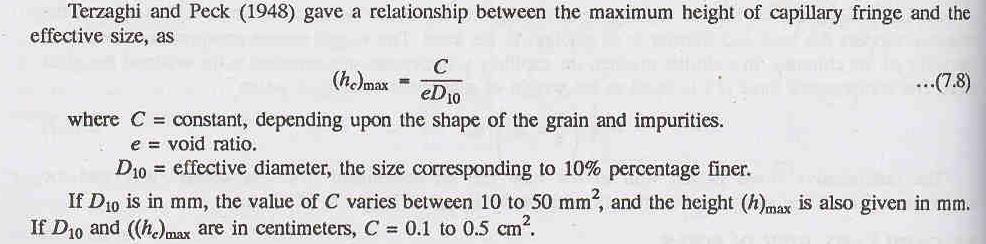
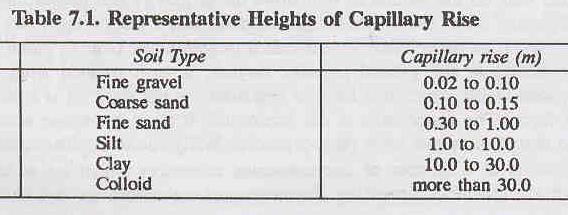
57 7.6: Capillarity Water Capillary: water that is drawn up above the water table. Intermediate Water: water which from a certain amount of rain water is hold by the action of surface tension. Soil Water: the zone effected by evaporation. 57

58 58
59 Example (4): find total stress, vertical stress and pore water pressure for the profile shown below 59

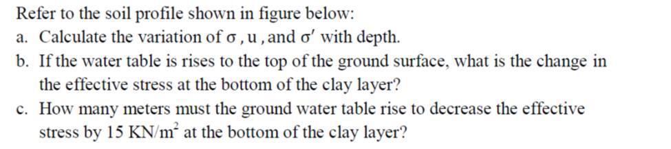
60 7.7: Question Bank of Chapter Seven 1) A sand deposit is 13m thick and overlies a bed of soft clay. The ground water table is 5m below the ground surface. If the sand above the ground water table has a degree of saturation of 45%, plot the diagram showing the variation of vertical total stress, pore water pressure and effective stress in the sand. The void ratio of the sand is 0.7. Take Gs=2.65 If the water table increased till it reached the ground surface, how much will be the difference in stresses. 2) The depth of water in a well is 3 m, below the bottom of the well lays a layer of sand 5 meters thick overlying a clay deposit. The specific gravity of the solids of sand and clay are respectively 2.64 and Their water contents are respectively 25 and 20 percent. Compute the total, effective and pore water pressures at points A and B shown in Figure below. If water in the well is pumped out up to the bottom of the well, estimate the change in the pressures at the points. 3) Calculate the horizontal stresses (total, effective and pore water pressure at point A, the angle of internal friction and unit weight of the soil are shown on the figure below. 60


61 4) 5) 61
62 Chapter Eight: One Dimensional Fluid Flow 8.1: The Aim of Studying the Fluid Flow in Soil 1- To determine rate of flow (quantity of water) beneath and through the earth dam. 2- To determine the strength of soil. 3- To determine the settlement of soil. 8.2: Definitions Any given mass of soil consists of solid particles of various sizes with interconnected void spaces. The continuous void spaces in a soil permit water to flow from a point of high energy to a point of low energy. Permeability is defined as the property of a soil that allows the seepage of fluids through its interconnected void spaces. Heads: The elevation head (he): is the Distance from the datum line to the point considered. Pressure head (hp): is the height to which the water raises in the piezometer. u= hp * γw Total head (ht): ht Piezometer: = hp + he The tube by which the water pressure can be m easured at any point in the soil. 62
63 There are two important points to be considered: 1- The flow between any two points depends on the difference of total head. 2-Any elevation head can be selected for a datum line. Darcy's Law : Darcy demonstrated experimentally that for laminar flow condition in saturated soil, the rate of flow or discharge per unit time is proportional to the hydraulic gradient. 63
 greater than 10-3mm/sec, it is classified as previous. If the soil is having (k) between (10-3 mm/sec- 10-5mm/sec), it is classified as semiprevious.")
64 Coefficient of Permeability (K): is the average velocity of flow that will occur through the total cross-sectional area of soil under unit hydraulic gradient. The unit is usually (m/day), (ft/day). If the soil is having (k) greater than 10-3mm/sec, it is classified as previous. If the soil is having (k) between (10-3 mm/sec- 10-5mm/sec), it is classified as semiprevious. If the soil is having (k) less than 10-5 mm/sec (imprevious) 8.3: Determination of Coefficient of Permeability 1- Laboratory Methods 2- Field Methods 3- Indirect Methods 4- Capillarity-Permeability Test 64
 Where L= length of")

65 1- Laboratory Methods: a- Constant Head Method: (Used for relatively more permeable soils) Where L= length of the specimen h=the head that causing flow The discharge q= the volume of the water collected divided by the time 65

 Consider the instant when the head is h.")


66 b- Variable-Head Method: (used for relatively less permeable soils because the quantity of water collected in the graduated jar of the constant head permeability test is very small and cannot be measured accurately.) Consider the instant when the head is h. For the small time dt, the head falls by dh. Then; 2- Field Methods: The coefficient of permeability of a soil deposit in-situ conditions can be determined by the following field methods: a- Pumping-out tests. b- Pumping-in tests. The pumping-out tests influence a large area around the pumping well and give an overall value of the coefficient of permeability of the soil deposit. The pumping-in tests influence a small area around the hole and therefore gives a value of the coefficient of permeability of the soil surrounding the hole. 3- Indirect Methods: 66
67 The coefficient of permeability of soil can also be determined indirectly from the soil parameters by (i) Computation from the particle size or its specific surface. Hazen conducted a formula for permeability for sand when the particle sizes between (0.1-3) mm (ii) Computation from the consolidation test data. 3- Capillarity-Permeability Test. 8.4: Factors affecting on the coefficient of permeability 1. Shape and size of the soil particles. 2. Void ratio: Permeability increases with increase in void ratio. 3. Degree of saturation: Permeability increases with increase in degree of saturation. 4. Composition of soil particles: For sands and silts this is not important; however, for soils with clay minerals this is one of the most important factors because permeability depends on the thickness of water held to the soil particles. 5. Soil structure: Fine-grained soils with a flocculated structure have a higher coefficient of permeability than those with a dispersed structure. 6. Viscosity of the permeant. 7. Density and concentration of the permeant. 67
68 Example (1): What is the value of permeability in mm/sec for a soil tested by using the head permeameter? The results were: t=4min Volume of water collected=300ml Difference in head=50mm Distance between points=100mm Dia. of sample=100mm Example (2): Find the value of permeability in mm/sec for a soil tested on the falling head permeability, Initial height of water=1500mm, Final height of water=605mm, Time of test=281sec, Length of sample=150mm, Diameter of sample=100mm, Diameter of the stand pipe=5mm 68

69 Example (3): Draw the elevation, pressure, and total heads for the system shown and find the velocity through the system. 69

70 Example (4): Draw the elevation, pressure and total heads for the system shown and find the velocity through the system. 70

71 Example (5): Draw the elevation, pressure and total heads for the system shown and find the velocity through the system 71

72 Example (6): Draw the elevation, pressure and total heads for the system shown and find the velocity through the system 72
 Assuming that there is no flow and the pressure is hydrostatic. 2) Taking the real case, that is having flow in upward direction inside the soil mass. 1 0.9 0.8 0.7 0.6 0.5 0.4 0.3 0.2 0.")
73 8.5: Effective Stress in Soil with Fluid Flow For the system shown, in order to see the effect of fluid flow through the soil on the effective stresses, let s consider two cases and compare the stresses: 1) Assuming that there is no flow and the pressure is hydrostatic. 2) Taking the real case, that is having flow in upward direction inside the soil mass he hp ht Elev. σv us u σ v(s) σ v

 A = ic= : critical hydraulic gradient.")
74 Seepage Force: *The seepage force acts on the direction of flow. *A force per unit volume of soil: J= = = * γw Thus, J= i * γw The total downward stress=z γw + γt * L The total upward stress= γw * (L+z+h) For equilibrium; Downward force= upward force (z γw + γt * L) A = γw * (L+z+h) A = ic= : critical hydraulic gradient. If ic= 1 then Quick Condition (Piping or Boiling will happen). At ic= 1 σ= u σ =0 74
 has strength even at zero effective stress then it does not necessarily become quick.")
75 Shear Strength =0 When a cohesion less soil (sand or gravel ) is subjected to water flow condition that result in a zero effective stress, the strength of soil becomes zero and quick condition thus exists. Because cohesive soil (clay) has strength even at zero effective stress then it does not necessarily become quick. Example (1) : A 125m layer of soil is subjected to an upward seepage head of 1.85m; what depth of coarse sand would be required above soil to provide a factor of safety against piping equals to 2; let γsat for both soils be 20.4 kn/m³ 75


76 8.6: Question Bank for Chapter Eight 1) 2) 76


77 3) 4) 77
78 9.1: Definitions Chapter Nine: Compaction In construction of highway embankments, earth dams and many other engineering structures, loose soils must be compacted to improve their strength by increasing their unit weight. Compaction is: Densification of soil by removing air voids using mechanical equipment; the degree of compaction is measured in terms of its dry unit weight. In general, soil densification includes: compaction and consolidation. Compaction: is one kind of densification that is realized by rearrangement of soil particles without outflow of water. It is realized by application of mechanic energy. It does not involve fluid flow, but with moisture changing altering. Consolidation: is another kind of densification with fluid flow away. Consolidation is primarily for saturated clayey soils. Water is squeezed out from its pores under load. 9.2: Objectives for Compaction 1- Increasing the bearing capacity of foundations; 2- Decreasing the undesirable settlement of structures; 3- Control undesirable volume changes; 4- Reduction in hydraulic conductivity; 5- Increasing the stability of slopes. 9.3: There are 4 control factors affecting the extent of compaction: 1. Compaction Effort: With the development of heavy rollers and their uses in field compaction, the Standard Proctor Test was modified to better represent field compaction As the compaction effort increases, the maximum dry unit weight of compaction increase The optimum moisture content decreases to some extend 78
79 2. Soil type and Gradation; Fine grain soil needs more water to reach optimum; and coarse grain soil needs less water to reach optimum. 3. Moisture Content; Water added to the soil during compaction acts as a softening agent on the soil particles, The dry unit weight (γ d ) increases as the moisture content increases TO A POINT Beyond a certain moisture content, any increase in moisture content tends to reduce the dry unit weight. 4. Dry unit weight (dry density). 9.4: Zero-air-void unit weight At certain water content, that is the unit weight to let no air in the voids, It is clear that in the above equation, specific gravity of the solid and the water density are constant, the zero-air-void density is inversely proportional to water content w. 79
80 For a given soil and water content the best possible compaction is represented by the zero-airvoids curve. The actual compaction curve will always be below. For dry soils the unit weight increases as water is added to the soil because the water lubricates the particles making compaction easier. As more water is added and the water content is larger than the optimum value, the void spaces become filled with water so further compaction is not possible because water is a kind like incompressible fluid. This is illustrated by the shape of the zero-air-voids curve which decreases as water content increases. General Notes: * According to the procedure of standard Proctor test and modified Proctor test, the soil must be sieved on sieve no.4 (4.75mm) before performing the test, but if the percentage of soil retained on a 4.75 mm sieve is more than20%, the larger mold of internal diameter, effective height of 127.3mm and capacity 2250 ml is used. In this case, 56 blows required for each layer. The rest of the procedure is similar to that in the standard Proctor test. *The placement water content when the sheep-foot rollers, smooth wheel rollers and vibratory rollers are used is of the order of the optimum water content obtained in modified Proctor test. *For important works, a full-scale test is conducted in the field to determine the placement water content, the thickness of the layer, mass and speed of the roller and the number of passes. Sometimes, in case of unimportant works, the placement water content is taken equal to the optimum water content of the Standard Proctor test for light compaction and equal to the modified Proctor test for heavy compaction. However, the field water content is sometimes kept intentionally different from the optimum water content in order to achieve or improve a specific engineering property of the soil. 9.5: Relative Compaction This term is occasionally used to describe the degree of compaction. Where: Relative Compaction R c = x 100% In highways degree of compaction of embankments usually varies from 90% to 100% of the Standard Proctor s Density. In earth dam construction the degree of compaction varies from 85 to 100% of Modified Proctor s Density. V.I. Note: There is a difference between the relative compaction (R c ) and the relative density (D r ) described in chapter three. 80
: 81")
81 Example (1): 81
: 82")
82 Example (2): 82
83 Example (3): 83


 3) 4)")
84 9.6: Question Bank for Chapter Nine 1) 2) 3) 4) 5) 84
85 List of Experiments: 1- Determination of moisture content 2- Specific gravity of soil solids 3- Sieve analysis 4- Hydrometer analysis 5- Liquid limit test 6- Plastic limit test 7- Shrinkage limit test 8- Constant head permeability test 9- Falling head permeability test 10- Standard Proctor test 11- Modified Procotr test Text Book: Soil Mechanics Laboratory I Soil Mechanics Laboratory Manual, Sixth Edition, Braja B. Das, New York, OXFORD UNIVERSITY PRESS,
86 86
87 87
88 88
89 89
90 90
91 91
92 92
93 93
94 94
95 95
96 96
97 97
98 98
99 99
100 100
101 101
102 102
103 103
104 104
105 105
106 106
107 107
108 108
109 109
110 110
111 111
112 112
113 113
114 114
115 115
116 116
117 117
118 118
119 119
120 120
121 121
122 122

123 123
124 124
125 125
126 126
127 127
128 128
129 129
130 130
131 131
132 132
133 133
134 134
135 135
136 136
137 137
138 138
139 139
140 140
141 141
142 142
143 143
144 144
145 145
146 146
147 147
148 148
149 149
150 150
151 151
152 152
153 153
154 154
155 155

156 156
Introduction to Soil Mechanics Geotechnical Engineering-II
 Introduction to Soil Mechanics Geotechnical Engineering-II ground SIVA Dr. Attaullah Shah 1 Soil Formation Soil derives from Latin word Solum having same meanings as our modern world. From Geologist point
This document downloaded from vulcanhammer.net vulcanhammer.info Chet Aero Marine
 This document downloaded from vulcanhammer.net vulcanhammer.info Chet Aero Marine Don t forget to visit our companion site http://www.vulcanhammer.org Use subject to the terms and conditions of the respective
Soil Mechanics. Chapter # 1. Prepared By Mr. Ashok Kumar Lecturer in Civil Engineering Gpes Meham Rohtak INTRODUCTION TO SOIL MECHANICS AND ITS TYPES
 Soil Mechanics Chapter # 1 INTRODUCTION TO SOIL MECHANICS AND ITS TYPES Prepared By Mr. Ashok Kumar Lecturer in Civil Engineering Gpes Meham Rohtak Chapter Outlines Introduction to Soil Mechanics, Soil
Chapter 1 - Soil Mechanics Review Part A
 Chapter 1 - Soil Mechanics Review Part A 1.1 Introduction Geotechnical Engineer is concerned with predicting / controlling Failure/Stability Deformations Influence of water (Seepage etc.) Soil behavour
CE 240 Soil Mechanics & Foundations Lecture 3.2. Engineering Classification of Soil (AASHTO and USCS) (Das, Ch. 4)
 (Das, Ch. 4)") CE 240 Soil Mechanics & Foundations Lecture 3.2 Engineering Classification of Soil (AASHTO and USCS) (Das, Ch. 4) Outline of this Lecture 1. Particle distribution and Atterberg Limits 2. Soil classification
CE 240 Soil Mechanics & Foundations Lecture 3.2 Engineering Classification of Soil (AASHTO and USCS) (Das, Ch. 4) Outline of this Lecture 1. Particle distribution and Atterberg Limits 2. Soil classification
1. INTRODUCTION 1.1 DEFINITIONS
 1. INTRODUCTION 1.1 DEFINITIONS The definition given to the word soil differs from one discipline to another. To a geologist, soil is the material found in the relatively thin surface region of the earth's
Geotechnical Properties of Soil
 Geotechnical Properties of Soil 1 Soil Texture Particle size, shape and size distribution Coarse-textured (Gravel, Sand) Fine-textured (Silt, Clay) Visibility by the naked eye (0.05 mm is the approximate
Table of Contents Chapter 1 Introduction to Geotechnical Engineering 1.1 Geotechnical Engineering 1.2 The Unique Nature of Soil and Rock Materials
 Table of Contents Chapter 1 Introduction to Geotechnical Engineering 1.1 Geotechnical Engineering 1.2 The Unique Nature of Soil and Rock Materials 1.3 Scope of This Book 1.4 Historical Development of Geotechnical
Geotechnical Engineering I CE 341
 Geotechnical Engineering I CE 341 What do we learn in this course? Introduction to Geotechnical Engineering (1) Formation, Soil Composition, Type and Identification of Soils (2) Soil Structure and Fabric
Module 1 GEOTECHNICAL PROPERTIES OF SOIL AND OF REINFORCED SOIL (Lectures 1 to 4)
") Module 1 GEOTECHNICAL PROPERTIES OF SOIL AND OF REINFORCED SOIL (Lectures 1 to 4) Topics 1.1 INTRODUCTION 1.2 GRAIN-SIZE DISTRIBUTION Sieve Analysis Hydrometer Analysis 1.3 SIZE LIMITS FOR SOILS 1.4 WEIGHT-VOLUME
Module 1 GEOTECHNICAL PROPERTIES OF SOIL AND OF REINFORCED SOIL (Lectures 1 to 4) Topics 1.1 INTRODUCTION 1.2 GRAIN-SIZE DISTRIBUTION Sieve Analysis Hydrometer Analysis 1.3 SIZE LIMITS FOR SOILS 1.4 WEIGHT-VOLUME
Solution:Example 1. Example 2. Solution: Example 2. clay. Textural Soil Classification System (USDA) CE353 Soil Mechanics Dr.
 CE353 Soil Mechanics Dr.") CE353 Soil Mechanics CE353 Lecture 5 Geotechnical Engineering Laboratory SOIL CLASSIFICATION Lecture 5 SOIL CLASSIFICATION Dr. Talat A Bader Dr. Talat Bader 2 Requirements of a soil Systems Why do we need
CE353 Soil Mechanics CE353 Lecture 5 Geotechnical Engineering Laboratory SOIL CLASSIFICATION Lecture 5 SOIL CLASSIFICATION Dr. Talat A Bader Dr. Talat Bader 2 Requirements of a soil Systems Why do we need
 Project: ITHACA-TOMPKINS REGIONAL AIRPORT EXPANSION Project Location: ITHACA, NY Project Number: 218-34 Key to Soil Symbols and Terms TERMS DESCRIBING CONSISTENCY OR CONDITION COARSE-GRAINED SOILS (major
Tikrit University. College of Engineering Civil engineering Department SOIL PROPERTES. Soil Mechanics. 3 rd Class Lecture notes Up Copyrights 2016
 Tikrit University SOIL PROPERTES College of Engineering Civil engineering Department Soil Mechanics 3 rd Class Lecture notes Up Copyrights 2016 1-Soil Composition -Solids -Water -Air 2-Soil Phases -Dry
The more common classification systems are enlisted below:
 A number of systems of classification have been evolved for categorizing various types of soil. Some of these have been developed specifically in connection with ascertaining the suitability of soil for
Soil Mechanics Brief Review. Presented by: Gary L. Seider, P.E.
 Soil Mechanics Brief Review Presented by: Gary L. Seider, P.E. 1 BASIC ROCK TYPES Igneous Rock (e.g. granite, basalt) Rock formed in place by cooling from magma Generally very stiff/strong and often abrasive
Chapter I Basic Characteristics of Soils
 Chapter I Basic Characteristics of Soils Outline 1. The Nature of Soils (section 1.1 Craig) 2. Soil Texture (section 1.1 Craig) 3. Grain Size and Grain Size Distribution (section 1.2 Craig) 4. Particle
4. Soil Consistency (Plasticity) (Das, chapter 4)
 (Das, chapter 4)") 4. Soil Consistency (Plasticity) (Das, chapter 4) 1 What is Consistency? Consistency is a term used to describe the degree of firmness of fine-grained soils (silt and clay). The consistency of fine grained
4. Soil Consistency (Plasticity) (Das, chapter 4) 1 What is Consistency? Consistency is a term used to describe the degree of firmness of fine-grained soils (silt and clay). The consistency of fine grained
SOIL FORMATION SOIL CLASSIFICATION FOR GEOTECHNICAL ENGINEERS. Soil Properties and Classification
 SOIL CLASSIFICATION FOR GEOTECHNICAL ENGINEERS Soil Properties and Classification Soil Formation Soil Types Particle Size Analysis and Grading Characteristics Consistency Indices Engineering classification
Instructor : Dr. Jehad Hamad. Chapter (7)
") Instructor : Dr. Jehad Hamad Chapter (7) 2017-2016 Soil Properties Physical Properties Mechanical Properties Gradation and Structure Compressibility Soil-Water Relationships Shear Strength Bearing Capacity
Instructor : Dr. Jehad Hamad Chapter (7) 2017-2016 Soil Properties Physical Properties Mechanical Properties Gradation and Structure Compressibility Soil-Water Relationships Shear Strength Bearing Capacity
Soil Mechanics Prof. B.V.S. Viswanadham Department of Civil Engineering Indian Institute of Technology, Bombay Lecture 3
 Soil Mechanics Prof. B.V.S. Viswanadham Department of Civil Engineering Indian Institute of Technology, Bombay Lecture 3 In the previous lecture we have studied about definitions of volumetric ratios and
Prof. B V S Viswanadham, Department of Civil Engineering, IIT Bombay
 06 Index properties Review Clay particle-water interaction Identification of clay minerals Sedimentation analysis Hydrometer analysis 0.995 20-40 Hydrometer is a device which is used to measure the specific
Course Scheme -UCE501: SOIL MECHANICS L T P Cr
 Course Scheme -UCE501: SOIL MECHANICS L T P Cr 3 1 2 4.5 Course Objective: To expose the students about the various index and engineering properties of soil. Introduction: Soil formation, various soil
A. V T = 1 B. Ms = 1 C. Vs = 1 D. Vv = 1
 Geology and Soil Mechanics 55401 /1A (2002-2003) Mark the best answer on the multiple choice answer sheet. 1. Soil mechanics is the application of hydraulics, geology and mechanics to problems relating
Geology and Soil Mechanics /1A ( ) Mark the best answer on the multiple choice answer sheet.
 Mark the best answer on the multiple choice answer sheet.") Geology and Soil Mechanics 55401 /1A (2003-2004) Mark the best answer on the multiple choice answer sheet. 1. Soil mechanics is the application of hydraulics, geology and mechanics to problems relating
Geology and Soil Mechanics 55401 /1A (2003-2004) Mark the best answer on the multiple choice answer sheet. 1. Soil mechanics is the application of hydraulics, geology and mechanics to problems relating
 QUESTION BANK DEPARTMENT: CIVIL SUBJECT CODE / Name: CE 2251 / SOIL MECHANICS SEMESTER: IV UNIT 1- INTRODUCTION PART - A (2 marks) 1. Distinguish between Residual and Transported soil. (AUC May/June 2012)
Soils. Technical English - I 10 th week
 Technical English - I 10 th week Soils Soil Mechanics is defined as the branch of engineering science which enables an engineer to know theoretically or experimentally the behavior of soil under the action
Tikrit University College of Engineering Civil engineering Department
 Tikrit University SOIL CLASSIFICATION College of Engineering Civil engineering Department Soil Mechanics 3 rd Class Lecture notes Up Copyrights 2016 Classification of soil is the separation of soil into
Clay Robinson, PhD, CPSS, PG copyright 2009
 Engineering: What's soil got to do with it? Clay Robinson, PhD, CPSS, PG crobinson@wtamu.edu, http://www.wtamu.edu/~crobinson, copyright 2009 Merriam-Webster Online Dictionary soil, noun 1 : firm land
Copyright SOIL STRUCTURE and CLAY MINERALS
 SOIL STRUCTURE and CLAY MINERALS Soil Structure Structure of a soil may be defined as the mode of arrangement of soil grains relative to each other and the forces acting between them to hold them in their
Topic 6: Weathering, Erosion and Erosional-Deposition Systems (workbook p ) Workbook Chapter 4, 5 WEATHERING
 Workbook Chapter 4, 5 WEATHERING") Topic 6: Weathering, Erosion and Erosional-Deposition Systems (workbook p. 95-125) Workbook Chapter 4, 5 THE BIG PICTURE: Weathering, erosion and deposition are processes that cause changes to rock material
Topic 6: Weathering, Erosion and Erosional-Deposition Systems (workbook p. 95-125) Workbook Chapter 4, 5 THE BIG PICTURE: Weathering, erosion and deposition are processes that cause changes to rock material
Dr. Ravi Kant mittal. CE C361 Soil Mechanics and Foundation Engg. 1
 Dr. Ravi Kant mittal Assistant Professor, BITS Pilani E- Mail: ravi.mittal@rediffmai.com ravimittal@bits-pilani.ac.in Mobile: 9887692025 CE C361 Soil Mechanics and Foundation Engg. 1 Contents Soil Formation
Principles of Foundation Engineering 8th Edition Das SOLUTIONS MANUAL
 Principles of Foundation Engineering 8th Edition SOLUTIONS MANUAL Full clear download (no formatting errors) at: https://testbankreal.com/download/principles-foundation-engineering- 8th-edition-das-solutions-manual/
Lecture Outline Wednesday - Friday February 14-16, 2018
 Lecture Outline Wednesday - Friday February 14-16, 2018 Quiz 2 scheduled for Friday Feb 23 (Interlude B, Chapters 6,7) Questions? Chapter 6 Pages of the Past: Sedimentary Rocks Key Points for today Be
UNIT 4 SEDIMENTARY ROCKS
 UNIT 4 SEDIMENTARY ROCKS WHAT ARE SEDIMENTS Sediments are loose Earth materials (unconsolidated materials) such as sand which are transported by the action of water, wind, glacial ice and gravity. These
Sediment. Weathering: mechanical and chemical decomposition and disintegration of rock and minerals at the surface
 Sediment Some basic terminology Weathering: mechanical and chemical decomposition and disintegration of rock and minerals at the surface Erosion: removal of weathered rock and minerals from one place to
PRINCIPLES OF GEOTECHNICAL ENGINEERING
 PRINCIPLES OF GEOTECHNICAL ENGINEERING Fourth Edition BRAJA M. DAS California State University, Sacramento I(T)P Boston Albany Bonn Cincinnati London Madrid Melbourne Mexico City New York Paris San Francisco
 SOIL CLASSIFICATION CHART COARSE-GRAINED SOILS MORE THAN 50% RETAINED ON NO.200 SIEVE FINE-GRAINED SOILS 50% OR MORE PASSES THE NO.200 SIEVE PRIMARY DIVISIONS GRAVELS MORE THAN 50% OF COARSE FRACTION RETAINED
Correlation of unified and AASHTO soil classification systems for soils classification
 Journal of Earth Sciences and Geotechnical Engineering, vol. 8, no. 1, 2018, 39-50 ISSN: 1792-9040 (print version), 1792-9660 (online) Scienpress Ltd, 2018 Correlation of unified and AASHTO classification
Assistant Prof., Department of Civil Engineering Bhagwant University,Ajmer,Rajasthan,India ABSTRACT
 Study of Index Properties of the Soil 1 Mr Utkarsh Mathur 2 Mr Nitin Kumar 3 Mr Trimurti Narayan Pandey 4 Mr.Amit Choudhary 1 PG Scholar, Department of Civil Engineering Bhagwant University,Ajmer,Rajasthan,India
Introduction to Soil Mechanics
 Introduction to Soil Mechanics Sela Sode and Colin Jones WILEY Blackwell Contents Preface Dedication and Acknowledgments List of Symbols Soil Structure 1.1 Volume relationships 1.1.1 Voids ratio (e) 1.1.2
Sedimentology & Stratigraphy. Thanks to Rob Viens for slides
 Sedimentology & Stratigraphy Thanks to Rob Viens for slides Sedimentology The study of the processes that erode, transport and deposit sediments Sedimentary Petrology The study of the characteristics and
Chapter 7 Permeability and Seepage
 Permeability and Seepage - N. Sivakugan (2005) 1 7.1 INTRODUCTION Chapter 7 Permeability and Seepage Permeability, as the name implies (ability to permeate), is a measure of how easily a fluid can flow
What factors affect the angle of a slope?
 Climate Rock type and Structure What factors affect the angle of a slope? Aspect Fast mass movements Slides: Slides are movements along the SLIP PLANE, i.e. a line of weakness in the rock or soil structure.
VALLIAMMAI ENGINEERING COLLEGE
 VALLIAMMAI ENGINEERING COLLEGE DEPARTMENT OF CIVIL ENGINEERING SUBJECT CODE : CE6405 YEAR : II SUBJECT NAME : SOIL MECHANICS SEM : IV QUESTION BANK (As per Anna University 2013 regulation) UNIT 1- SOIL
Figure 1 The map shows the top view of a meandering stream as it enters a lake. At which points along the stream are erosion and deposition dominant?
 1. In which type of climate does chemical weathering usually occur most rapidly? 1. hot and dry 3. cold and dry 2. hot and wet 4. cold and wet 2. Figure 1 The map shows the top view of a meandering stream
Boreholes. Implementation. Boring. Boreholes may be excavated by one of these methods: 1. Auger Boring 2. Wash Boring 3.
 Implementation Boreholes 1. Auger Boring 2. Wash Boring 3. Rotary Drilling Boring Boreholes may be excavated by one of these methods: 4. Percussion Drilling The right choice of method depends on: Ground
EPS 50 Lab 4: Sedimentary Rocks
 Name: EPS 50 Lab 4: Sedimentary Rocks Grotzinger and Jordan, Chapter 5 Introduction In this lab we will classify sedimentary rocks and investigate the relationship between environmental conditions and
Depth (ft) USCS Soil Description TOPSOIL & FOREST DUFF
 USCS Soil Description TOPSOIL & FOREST DUFF") Test Pit No. TP-6 Location: Latitude 47.543003, Longitude -121.980441 Approximate Ground Surface Elevation: 1,132 feet Depth (ft) USCS Soil Description 0 1.5 1.5 5.0 SM 5.0 8.0 SM Loose to medium dense,
Test Pit No. TP-6 Location: Latitude 47.543003, Longitude -121.980441 Approximate Ground Surface Elevation: 1,132 feet Depth (ft) USCS Soil Description 0 1.5 1.5 5.0 SM 5.0 8.0 SM Loose to medium dense,
J. Paul Guyer, P.E., R.A.
 J. Paul Guyer, P.E., R.A. Paul Guyer is a registered mechanical engineer, civil engineer, fire protection engineer and architect with over 35 years experience in the design of buildings and related infrastructure.
Chapter 2. 53% v. 2.2 a. From Eqs. (2.11) and (2.12), it can be seen that, 2.67
 and (2.12), it can be seen that, 2.67") Chapter 2 2.1 d. (87.5)(9.81) (1000)(0.05) 3 17.17 kn/m c. d 1 w 17.17 1 0.15 3 14.93 kn/m G a. Eq. (2.12): s w (2.68)(9.81). 14.93 ; e 0.76 1 e 1 e e 0.76 b. Eq. (2.6): n 0.43 1 e 1 0.76 Vw wgs (0.15)(2.68)
Chapter 2 2.1 d. (87.5)(9.81) (1000)(0.05) 3 17.17 kn/m c. d 1 w 17.17 1 0.15 3 14.93 kn/m G a. Eq. (2.12): s w (2.68)(9.81). 14.93 ; e 0.76 1 e 1 e e 0.76 b. Eq. (2.6): n 0.43 1 e 1 0.76 Vw wgs (0.15)(2.68)
Sediment and sedimentary rocks Sediment
 Sediment and sedimentary rocks Sediment From sediments to sedimentary rocks (transportation, deposition, preservation and lithification) Types of sedimentary rocks (clastic, chemical and organic) Sedimentary
Soil Mechanics Course Contents
 / Soil Mechanics Course Contents Instructor: Asst. Prof. Mahdi O. Karkush (Ph.D., CE, MISSMGE)) E-mail: mahdi_karkush@coeng.uobaghdad.edu.iq Tel.: Prerequisite: Solid Mechanics, Engineering Mechanics and
APPENDIX A. Borehole Logs Explanation of Terms and Symbols
 APPENDIX A Borehole Logs Explanation of Terms and Symbols Page 153 of 168 EXPLANATION OF TERMS AND SYMBOLS The terms and symbols used on the borehole logs to summarize the results of field investigation
*** ***! " " ) * % )!( & ' % # $. 0 1 %./ +, - 7 : %8% 9 ) 7 / ( * 7 : %8% 9 < ;14. " > /' ;-,=. / ١
 * % )!( & ' % # $. 0 1 %./ +, - 7 : %8% 9 ) 7 / ( * 7 : %8% 9 < ;14. > /' ;-,=. / ١") ١ ******!" #$ % & '!( ) % * ") +,-./ % 01. 3 ( 4 56 7/4 ) 8%9 % : 7 ;14 < 8%9 % : *7./ = ;-, >/'." Soil Permeability & Seepage ٢ Soil Permeability- Definition ٣ What is Permeability? Permeability is the
١ ******!" #$ % & '!( ) % * ") +,-./ % 01. 3 ( 4 56 7/4 ) 8%9 % : 7 ;14 < 8%9 % : *7./ = ;-, >/'." Soil Permeability & Seepage ٢ Soil Permeability- Definition ٣ What is Permeability? Permeability is the
SHEAR STRENGTH OF SOIL
 SHEAR STRENGTH OF SOIL Necessity of studying Shear Strength of soils : Soil failure usually occurs in the form of shearing along internal surface within the soil. Shear Strength: Thus, structural strength
Class Principles of Foundation Engineering CEE430/530
 Class Principles of Foundation Engineering CEE430/530 1-1 General Information Lecturer: Scott A. Barnhill, P.E. Lecture Time: Thursday, 7:10 pm to 9:50 pm Classroom: Kaufmann, Room 224 Office Hour: I have
SOIL AND AGGREGATE FUNDAMENTALS STUDENT GUIDE AMRC April, 2006 AREA MANAGER ROADS CERTIFICATION PROGRAM FOR EDUCATIONAL PURPOSES ONLY
 AREA MANAGER ROADS CERTIFICATION PROGRAM AMRC 2011 SOIL AND AGGREGATE FUNDAMENTALS STUDENT GUIDE FOR EDUCATIONAL PURPOSES ONLY April, 2006 WPC #28013 07/09 2009 by British Columbia Institute of Technology
Collapsible Soils Definitions
 Collapsible Soils Definitions Collapsible soils are also known as metastable soils. They are unsaturated soils that undergo a large volume change upon saturation. The sudden and usually large volume change
Prof. B V S Viswanadham, Department of Civil Engineering, IIT Bombay
 05 Clay particle-water interaction & Index properties Electrical nature of clay particles a) Electrical charges i) The two faces of all platy particles have a negative charge. Resulting due to isomorphous
Geology 229 Engineering Geology. Lecture 8. Elementary Soil Mechanics (West, Ch. 7)
") Geology 229 Engineering Geology Lecture 8 Elementary Soil Mechanics (West, Ch. 7) Outline of this Lecture 1. Introduction of soil properties 2. Index properties of soils Soil particles Phase relationship
Geology 229 Engineering Geology Lecture 8 Elementary Soil Mechanics (West, Ch. 7) Outline of this Lecture 1. Introduction of soil properties 2. Index properties of soils Soil particles Phase relationship
Prof. B V S Viswanadham, Department of Civil Engineering, IIT Bombay
 19 Module 5: Lecture -1 on Stability of Slopes Contents Stability analysis of a slope and finding critical slip surface; Sudden Draw down condition, effective stress and total stress analysis; Seismic
1/31/2013. Weathering Includes Physical, Chemical, Biological processes. Weathering Mechanisms. Wind abrasion forming Ventifacts
 Monument Valley, Utah. What weathering processes contributed to the development of these remarkable rock formations? Weathering Includes Physical, Chemical, Biological processes Weathering Mechanisms Physical
SOIL MECHANICS SAB1713 DR. HETTY
 SOIL MECHANICS SAB1713 DR. HETTY INTRODUCTION SOIL MECHANICS -Concerned solely with soils -Concerned with the deformation and strength of bodies of soils -Concerned with the interaction of structures with
Chapter 5 Shear Strength of Soil
 Page 5 Chapter 5 Shear Strength of Soil. The internal resistance per unit area that the soil mass can offer to resist failure and sliding along any plane inside it is called (a) strength (b) shear strength
CE 240 Soil Mechanics & Foundations Lecture 5.2. Permeability III (Das, Ch. 6) Summary Soil Index Properties (Das, Ch. 2-6)
 Summary Soil Index Properties (Das, Ch. 2-6)") CE 40 Soil Mechanics & Foundations Lecture 5. Permeability III (Das, Ch. 6) Summary Soil Index Properties (Das, Ch. -6) Outline of this Lecture 1. Getting the in situ hydraulic conductivity 1.1 pumping
CE 40 Soil Mechanics & Foundations Lecture 5. Permeability III (Das, Ch. 6) Summary Soil Index Properties (Das, Ch. -6) Outline of this Lecture 1. Getting the in situ hydraulic conductivity 1.1 pumping
Soil Mechanics/Geotechnical Engineering I Prof. Dilip Kumar Baidya Department of Civil Engineering Indian Institute of Technology, Kharagpur
 Soil Mechanics/Geotechnical Engineering I Prof. Dilip Kumar Baidya Department of Civil Engineering Indian Institute of Technology, Kharagpur Lecture - 01 Rock Cycle Good morning. I welcome you to this
Soil Properties - I. Amit Prashant. Indian Institute of Technology Gandhinagar. Short Course on. Geotechnical Aspects of Earthquake Engineering
 Soil Properties - I Amit Prashant Indian Institute of Technology Gandhinagar Short Course on Geotechnical Aspects of Earthquake Engineering 04 08 March, 2013 Regional Soil Deposits of India Alluvial deposits
Name. 4. The diagram below shows a soil profile formed in an area of granite bedrock. Four different soil horizons, A, B, C, and D, are shown.
 Name 1. In the cross section of the hill shown below, which rock units are probably most resistant to weathering? 4. The diagram below shows a soil profile formed in an area of granite bedrock. Four different
Sediment and Sedimentary rock
 Sediment and Sedimentary rock Sediment: An accumulation of loose mineral grains, such as boulders, pebbles, sand, silt or mud, which are not cemented together. Mechanical and chemical weathering produces
Introduction to Geotechnical Engineering. ground
 Introduction to Geotechnical Engineering ground 1 Typical Geotechnical Project Geo-Laboratory ~ for testing soil properties Design Office ~ for design & analysis construction site 2 Shallow Foundations
Chapter (12) Instructor : Dr. Jehad Hamad
 Instructor : Dr. Jehad Hamad") Chapter (12) Instructor : Dr. Jehad Hamad 2017-2016 Chapter Outlines Shear strength in soils Direct shear test Unconfined Compression Test Tri-axial Test Shear Strength The strength of a material is the
Chapter (12) Instructor : Dr. Jehad Hamad 2017-2016 Chapter Outlines Shear strength in soils Direct shear test Unconfined Compression Test Tri-axial Test Shear Strength The strength of a material is the
Lab 7: Sedimentary Structures
 Name: Lab 7: Sedimentary Structures Sedimentary rocks account for a negligibly small fraction of Earth s mass, yet they are commonly encountered because the processes that form them are ubiquitous in the
Mechanical Weathering
 Weathering is the disintegration and decomposition of material at or near the surface. Erosion is the incorporation and transportation of material by a mobile agent, usually water, wind, or ice. Geologists
The Production of Sediment. Contents. Weathering. Chapters 1, 3
 The Production of Sediment Chapters 1, 3 Contents Weathering Physical, chemical, biogeochemical processes Rates Products Carbon cycle and global change Erosion/Soils Sediment Texture Weathering General
Theory of Shear Strength
 MAJ 1013 ADVANCED SOIL MECHANICS Theory of Shear Strength Prepared by, Dr. Hetty 1 Strength of different materials Steel Concrete Soil Tensile strength Compressive strength Shear strength Complex behavior
The physical breakdown and chemical alteration of rocks and minerals at or near Earth s surface.
 The physical breakdown and chemical alteration of rocks and minerals at or near Earth s surface. The material that is chemically and mechanically weathered to yield sediment and soil. Regolith consisting
Weathering, Erosion, Deposition, and Landscape Development
 Weathering, Erosion, Deposition, and Landscape Development I. Weathering - the breakdown of rocks into smaller particles, also called sediments, by natural processes. Weathering is further divided into
Assessment of accuracy in determining Atterberg limits for four Iraqi local soil laboratories
 IOP Conference Series: Materials Science and Engineering PAPER OPEN ACCESS Assessment of accuracy in determining Atterberg limits for four Iraqi local soil laboratories To cite this article: H O Abbas
B-1 BORE LOCATION PLAN. EXHIBIT Drawn By: 115G BROOKS VETERINARY CLINIC CITY BASE LANDING AND GOLIAD ROAD SAN ANTONIO, TEXAS.
 N B-1 SYMBOLS: Exploratory Boring Location Project Mngr: BORE LOCATION PLAN Project No. GK EXHIBIT Drawn By: 115G1063.02 GK Scale: Checked By: 1045 Central Parkway North, Suite 103 San Antonio, Texas 78232
Theory of Shear Strength
 SKAA 1713 SOIL MECHANICS Theory of Shear Strength Prepared by, Dr. Hetty 1 SOIL STRENGTH DEFINITION Shear strength of a soil is the maximum internal resistance to applied shearing forces The maximum or
B.E. (Civil) Semester: V Subject Name: GEOTECHNICAL ENGINEERING-I (CV503)
 Semester: V Subject Name: GEOTECHNICAL ENGINEERING-I (CV503)") B.E. (Civil) Semester: V Subject Name: GEOTECHNICAL ENGINEERING-I (CV503) A. Course Objective: To provide a coherent development to the students for the courses in sector of Engineering like Geotechnical
B.E. (Civil) Semester: V Subject Name: GEOTECHNICAL ENGINEERING-I (CV503) A. Course Objective: To provide a coherent development to the students for the courses in sector of Engineering like Geotechnical
Wikipedia.org BUILDING STONES. Chapter 4. Materials of Construction-Building Stones 1
 Wikipedia.org BUILDING STONES Chapter 4 Materials of Construction-Building Stones 1 What is Stone? Stone is a concretion of mineral matter. Used either as a; Construction material, Manufacture of other
Introduction to Soil Mechanics Geotechnical Engineering
 Introduction to Soil Mechanics Geotechnical Engineering Dr. Attaullah Shah ground SIVA 1 Soil Mechanics= Soil+Mechanics Branch of Science dealing with the structure, Engineering properties and reactions
Field Exploration. March 31, J-U-B ENGINEERS, Inc. 115 Northstar Avenue Twin Falls, Idaho Attn: Mr. Tracy Ahrens, P. E. E:
 March 31, 201 11 Northstar Avenue 83301 Attn: Mr. Tracy Ahrens, P. E. E: taa@jub.com Re: Geotechnical Data Report Preliminary Phase 1 Field Exploration Revision No. 1 Proposed Rapid Infiltration Basin
 Photo 1 - Southerly view across 2700 parking lot toward existing building. Multi-residential building borders western side of property in upper right of view. Photo 2 - Southerly view across 2750 parking
What are the different ways rocks can be weathered?
 Romano - 223 What are the different ways rocks can be weathered? Weathering - the breakdown of rocks and minerals at the Earth s surface 1. 2. PHYSICAL WEATHERING Rock is broken into smaller pieces with
NC Earth Science Essential Standards
 NC Earth Science Essential Standards EEn. 2.1 Explain how processes and forces affect the Lithosphere. EEn. 2.1.1 Explain how the rock cycle, plate tectonics, volcanoes, and earthquakes impact the Lithosphere.
Mass Wasting. Revisit: Erosion, Transportation, and Deposition
 Mass Wasting Revisit: Erosion, Transportation, and Deposition While landslides are a normal part of erosion and surface processes, they can be very destructive to life and property! - Mass wasting: downslope
1. Introduction 2 Introduction to Soil Mechanics and Soil Engineering; Complexity of soil nature; Soil formation and soil types. 2.
 CONTENTS PAGE NO 1. Introduction 2 Introduction to Soil Mechanics and Soil Engineering; Complexity of soil nature; Soil formation and soil types. 2. Simple Soil Properties 5 Basic definitions; Phase relations;
To get you thinking Explain how these different layers of rock formed? Why are these layers different colors? Sedimentary Rocks
 To get you thinking Explain how these different layers of rock formed? Why are these layers different colors? Sedimentary Rocks Bryce Canyon, Utah Badlands, South Dakota Weathering Whenever rock is exposed
Geology 229 Engineering Geology. Lecture 7. Rocks and Concrete as Engineering Material (West, Ch. 6)
") Geology 229 Engineering Geology Lecture 7 Rocks and Concrete as Engineering Material (West, Ch. 6) Outline of this Lecture 1. Rock mass properties Weakness planes control rock mass strength; Rock textures;
Geology 229 Engineering Geology Lecture 7 Rocks and Concrete as Engineering Material (West, Ch. 6) Outline of this Lecture 1. Rock mass properties Weakness planes control rock mass strength; Rock textures;
Sedimentary Rocks. Weathering. Mechanical & Chemical Weathering. Sediments. Lithification. Deposition. Transport. Erosion.
 Lithification Sedimentary Rocks Sediments Deposition Transport Erosion Weathering Weathering The sediments that make up sedimentary rocks are produced by: Mechanical & Chemical Weathering Mechanical Weathering
Objectives. Introduction to Soils. Terms to know: What is soil? Study of Soils. The Soil Body 11/9/2012
 Objectives Explain what soil is and where it comes from Define a soil body List examples of the five soil-forming factors Explain how soils develop Introduction to Soils Terms to know: What is soil? Alluvial
Weathering, Erosion and Deposition
 Weathering, Erosion and Deposition Shaping the Earth s Surface Weathering the process of breaking down rocks into smaller fragments Erosion the transport of rock fragments from one location to another
Chapter a. True b. False c. True d. True e. True. Percent retained on each sieve
 Chapter 2 2.1 a. True b. False c. True d. True e. True 2.2 a. Sieve No. 4 10 20 40 60 100 200 Pan Mass of soil retained on each sieve (g) 0.0 18.5 53.2 90.5 81.8 92.2 58.5 26.5 Σ421.2 g Percent retained
ARCH 1250 APPLIED ENVIRONMENTAL STUDIES
 John Seitz, RA, LEED AP Assistant Adjunct Professor Professor Paul C. King, RA, AIA, ARA Assistant Professor Geology Geology is the scientific study of the structure and composition of the earth s surface
The process of determining the layers of natural soil deposits that will underlie a proposed structure and their physical properties is generally
 The process of determining the layers of natural soil deposits that will underlie a proposed structure and their physical properties is generally referred to as sub surface investigation 2 1 For proper
Geology 229 Engineering Geology. Lecture 6. Basic Rock Classification and Engineering Considerations (West, Chs. 2, 3, 4, 5)
") Geology 229 Engineering Geology Lecture 6 Basic Rock Classification and Engineering Considerations (West, Chs. 2, 3, 4, 5) Outline of this Lecture 1. Rock types and rock cycle 2. Geological and engineering
Geology 229 Engineering Geology Lecture 6 Basic Rock Classification and Engineering Considerations (West, Chs. 2, 3, 4, 5) Outline of this Lecture 1. Rock types and rock cycle 2. Geological and engineering
FUNDAMENTALS SOIL MECHANICS. Isao Ishibashi Hemanta Hazarika. >C\ CRC Press J Taylor & Francis Group. Taylor & Francis Group, an Informa business
 SOIL MECHANICS FUNDAMENTALS Isao Ishibashi Hemanta Hazarika >C\ CRC Press J Taylor & Francis Group Boca Raton London New York CRC Press is an imprint of the Taylor & Francis Group, an Informa business
Section I: Multiple Choice Select the best answer to each question. Mark your final answer on the answer sheet. (1 pt each)
") Sedimentary Rocks & Surface Processes Quest Name: Earth Science 2013 Block: Date: Section I: Multiple Choice Select the best answer to each question. Mark your final answer on the answer sheet. (1 pt each)
Sedimentary Rocks & Surface Processes Quest Name: Earth Science 2013 Block: Date: Section I: Multiple Choice Select the best answer to each question. Mark your final answer on the answer sheet. (1 pt each)