Seismologia A Seismology A Lecture 9: Engineering seismology: seismic veloci:es in soils
|
|
|
- Alberta Lang
- 5 years ago
- Views:
Transcription
1 Seismologia A Seismology A Lecture 9: Engineering seismology: seismic veloci:es in soils h<p://nptel.ac.in/downloads/ / New manual of seismological observatory prac:ce, Chapter 14 h<p:// CampbellCh_BerteroBozorgnia.pdf h<p:// design/files/an%20overview%20of %20Earthquake%20Engineering%20(DCR).pdf Materials from the web- page by David M. Boore (USGS) were used: h<p://
2 1. Seismic veloci:es in soils 2. Convolu:onal model of wave propaga:on 3. Methods based on body waves, resolu:on of body wave methods
 30 m GEOTECHNICAL BEDROCK It is composed of a soil column")


3 NEAR- SURFACE The Near- Surface In engineering seismology, the near- surface is defined as the layer below the free surface with a few tens of meters of thickness (V s30 is S- wave velocity) 30 m GEOTECHNICAL BEDROCK It is composed of a soil column of fine- grained material (silt, clay, and sand), and coarse- grained material (gravel, cobble, and conglomerate), and it may also include low- velocity, unconsolidated, heterogeneous, and highly weathered, poorly cohesive rocky soil. Within the context of geotechnical engineering, we shall make reference to the near- surface as the soil column. The subsurface, which is oeen referred to as the bedrock, is composed of rela:vely higher velocity, consolidated layers of sedimentary and crystalline rocks.
4 STRESS, STRAIN AND ELASTIC MODULI Young modulus Elastic field Ductile field Fracture point E = longitudinal stress F A longitudinal strain Dl l Bulk modulus Stress Yield point K = volume stress P volume strain Dv v Shear modulus Strain Fig. 3.1 A typical stress strain curve for a solid body. m = shear stress t shear strain tan q
5 ELASTIC MODULI AND SEISMIC VELOCITIES (Evere<, 2011)
6 (Evere<, 2011) rffiffiffi V S V P ¼ sffiffiffiffiffiffiffiffiffiffiffiffiffiffiffiffiffi 1 2, 2(1 )

7 PROPAGATION OF SEISMIC WAVES (Den:th and Mulge, 2014) 7
 8")
8 (Mulge, 2014) 8

9 P- WAVES:
10
 are considered assignal that need to be")
11 Body waves Two groups of methods In engineering seismology: 1) Methods using body waves Reflec:on Refrac:on 2) Methods using surface waves This is different from explora:on seismology in which surface waves (ground roll) are considered assignal that need to be removed.

12 Porosity in earth sciences and construchon Used in geology, hydrogeology, soil science, and building science, the porosity of a porous medium (such as rock or sediment) describes the frac:on of void space in the material, where the void may contain, for example, air or water. It is defined by the ra:o: φ = V v / V T, where V v is the volume of void- space (such as fluids) and V T is the total or bulk volume of material, including the solid and void components. Porosity is a frac:on between 0 and 1, typically ranging from less than 0.01 for solid granite to more than 0.5 for peat and clay. It may also be represented in percent terms.
13 For a given lithologic composi:on, seismic wave veloci:es in rocks are influenced by porosity, pore shape, pore pressure, pore fluid satura:on, confining pressure, and temperature. These factors have been inves:gated extensively under laboratory condi:ons.
14 Results of laboratory measurements in sedimentary rocks (a) Change of P- and S- wave veloci:es as a func:on of confining pressure observed in dry and water- saturated Bedford limestone samples with pores in the form of microcracks. Fluid volume has been kept constant during measurements. (b) Change of P- and S{wave veloci:es as a func:on of confining pressure observed in Berea sandstone samples with rounded pores. Fluid volume has been kept constant during measurements. Here, S: saturated, D: dry, VP : P- wave velocity, and VS : S- wave velocity. (Adapted from Nur, 1981.)
15 Seismic Wave VelociHes in Soils Seismic wave veloci:es in soils are influenced by porosity, pore shape, pore pressure, pore fluid satura:on, confining pressure, temperature.
16 The P- and S- wave veloci:es for a near- surface soil material with typical composi:on of sand, silt, and clay always are much lower than those for subsurface rocks. The P- wave veloci:es within a shallow soil column may be as low as 400 m/s or even lower, and may increase with depth of the soil column to 2000 m/s or higher. The S- wave veloci:es within a shallow soil column may be as low as 100 m/s or even lower, and may increase with depth of the soil column to 700 m/s, which usually is characterized as the geotechnical bedrock limit.
.")
17 A composite graph of the P- wave velocity- depth func:ons es:mated by travel:me inversion of seismic data recorded at 27 strong- mo:on seismograph sta:ons in Turkey soils composed of fine- grained material (sand, clay, and silt). Cri:cal depth of compac:on (CDC) The solid red curves represent the upper (UB) and lower (LB) bounds of the velocity varia:ons with depth, and the broken red curves VP and VS represent the average velocity varia:ons with depth
18 A composite graph of the S- wave velocity- depth func:ons es:mated by Rayleigh- wave inversion of seismic data recorded at 27 strong- mo:on seismograph sta:ons in Turkey soils composed of fine- grained material (sand, clay, and silt). The solid red curves represent the upper (UB) and lower (LB) bounds of the velocity varia:ons with depth, and the broken red curves VP and VS represent the average velocity varia:ons with depth Cri:cal depth of compac:on (CDC)

19 DIFFERENT SOIL TYPE: In addi:on to fine- grained alluvial material sand, clay, shale, and silt with varying percentages the soil profiles at some of these sta:ons are composed of coarse- grained material such as gravelly sand and clay Composite graph of the P- wave velocity- depth profiles es:mated by travel:me inversion Cri:cal depth of compac:on (CDC)
20 DIFFERENT SOIL TYPE: In addi:on to fine- grained alluvial material sand, clay, shale, and silt with varying percentages the soil profiles at some of these sta:ons are composed of coarse- grained material such as gravelly sand and clay The image cannot be displayed. Your computer may not have enough memory to open the image, or the image may have been corrupted. Restart your computer, and then open the file again. If the red x still appears, you may have to delete the image and then insert it again. Composite graph of the S- wave velocity- depth profiles es:mated from surface wave dispersion Cri:cal depth of compac:on (CDC)
: Cri:cal depth of compac:on")
21 A composite graph of the V P / V S ra:o as a func:on of depth associated with the P- and S- wave velocity- depth func:ons in previous slides (fine grained soils): Cri:cal depth of compac:on (CDC)
22 A composite graph of the V P / V S ra:o as a func:on of depth associated with the P- and S- wave velocity- depth func:ons in previous slides (coarse grained soils): Cri:cal depth of compac:on (CDC)
23 Both P- and S- wave veloci:es increase with increasing depth. Because confining pressure associated with the overburden increases with depth, equivalently, both P- and S- wave veloci:es increase with increasing confining pressure. Regardless of confining pressure or depth, P- wave velocity is greater than S- wave velocity. This is true for any soil type. P- wave velocity generally increases rapidly with depth at a shallow depth interval of 0-10 m, then increases slowly at a greater depth interval of m. This occurs because pores close as the confining pressure increases. Based on the change in ver:cal velocity gradient, especially that of the S- wave velocity, this depth may be defined as the crihcal depth of compachon (CDC). The soil column above the cri:cal depth of compac:on (CDC) is unconsolidated and the soil column below the CDC is consolidated.
24 POISSON S RATIO (Fine grained sediments) Poisson's ra:o is a strong indicator of fluid satura:on. The higher the Poisson's ra:o, the more saturated the soil. Undrained soil has a Poisson's ra:o of 0.5 (Coduto, 1999)
25 POISSON S RATIO (coarse grained sediments) Poisson's ra:o is a strong indicator of fluid satura:on. The higher the Poisson's ra:o, the more saturated the soil. Undrained soil has a Poisson's ra:o of 0.5 (Coduto, 1999)
 REFLECTION 2)")
26 TWO MAIN GROUPS OF BODY WAVE METHODS: 1) REFLECTION 2) REFRACTION
27
28
29 Par::oning of a unit- amplitude incident P- wave energy into four components: reflected and refracted P- and S- waves. (Aeer Richards, 1961.)
")
30 (Den:th and Mulge, 2014) 30
31
32
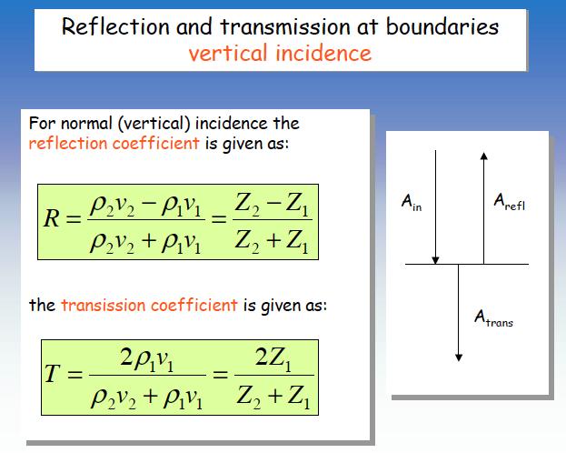
33 The ConvoluHonal Model Assump:on 1. The earth is made up of horizontal layers of constant velocity. Assump:on 2. The source generates a compressional plane wave that impinges on layer boundaries at normal incidence. (Under such circumstances, no shear waves are generated) Assump:on 3. The source waveform does not change as it travels in the subsurface, it is sta:onary.
 We input a")
 is the convolution of the two S")
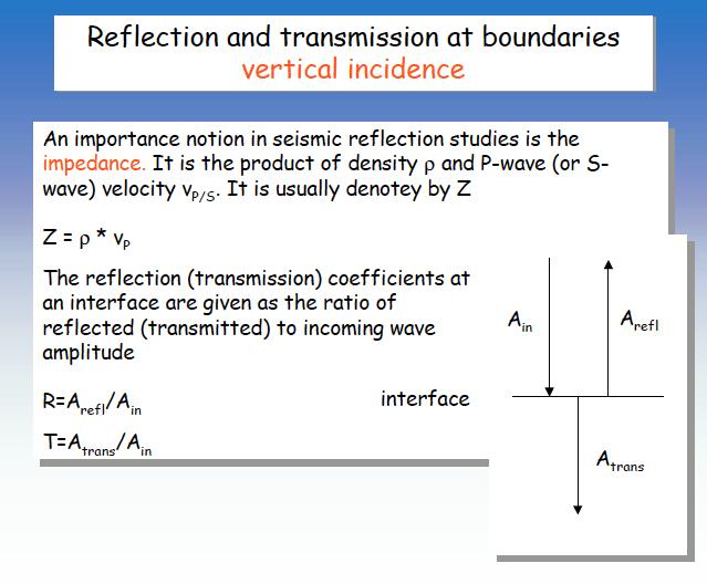
34 Reflectivity and convolution The seismic wave is sensitive to the sequence of impedance contrasts The reflectivity series (R) We input a source wavelet (W) which is reflected at each impedance contrast The seismogram recorded at the surface (S) is the convolution of the two S = W * R
35 Convolution Reflectivity series 1 ½ ½ Source wavelet ½ -½ 1 Output 0 Recorded waveform
36 Convolution Reflectivity series 1 ½ ½ Source wavelet ½ -½ 1 Output 0 1 Recorded waveform
37 Convolution Reflectivity series 1 ½ ½ Source wavelet ½ -½ 1 Output 0 1 Recorded waveform
38 Convolution Reflectivity series Source wavelet 1 ½ ½ -½ 1 ½ Output Recorded waveform
39 Convolution Reflectivity series 1 ½ ½ Source wavelet ½ -½ 1 Output ¾ Recorded waveform
40 Convolution Reflectivity series 1 ½ ½ Source wavelet ½ -½ 1 Output ¾ 0 Recorded waveform
41 VERTICAL RESOLUTION The ver:cal resolu:on is a measure of the ability to recognize individual, closely- spaced reflectors and is determined by the pulse length on the recorded seismic sec:on. For a reflected pulse represented by a simple wavelet, the maximum resolu:on possible is between one- quarter and one- eighth of the dominant wavelength of the pulse f (t) t EXAMPLE: for a reflec:on survey involving a signal with a dominant frequency of 50 Hz propaga:ng in sedimentary strata with a velocity of 2.0 km/s, the dominant wavelength would be 40m and the ver:cal resolu:on may therefore be no be<er than about 10 m.
42
43 Table 1-1a. Threshold (=4) for P-wave vertical resolution. =4 ¼ V P =4f V P (m/s) f (Hz) =4 (m) Table 1-1b. Threshold (=4) for S-wave vertical resolution. =4 ¼ V S =4f V S (m/s) f (Hz) =4 (m)


44 Profile Design Example-1: Design on Receiver Distance Shot Point Geophone Target Depth~ 3m 0.6m 0.6m Then, what is the receiver distance regarding the target depth or vice versa? Refraction Design is over. Receiver spacing (dx) is about 1/5 the max depth of target depth (z) What is the resolution? 0.3 m

45 HORIZONTAL RESOLUTION Reflector Source Fresnel zone Fig Energy is returned to source from all points of a reflector.the part of the reflector from which energy is returned within half a wavelength of the initial reflected arrival is known as the Fresnel zone. l 4 There are two main controls on the horizontal resolu:on of a reflec:on survey: 1) One is intrinsic to the physical process of reflec:on (wavefront size) 2) the other is determined by the detector spacing. The width of the first Fresnel zone for the reflector at depth z: x 12 w = ( 2zl) for z >> ( l) 0.5x Fig The horizontal sampling of a seismic reflection survey is half the detector spacing.
 must be 1/8 to ¼ the wavelength (two way")

46 Resolution of structure Consider a vertical step in an interface To be detectable the step must cause an delay of ¼ to ½ a wavelength This means the step (h) must be 1/8 to ¼ the wavelength (two way traveltime) Example: 20 Hz, = 4.8 km/s then = 240 m Therefore need an offset greater than 30 m Shorter wavelength signal (higher frequencies) have better resolution. What is the problem with very high frequency sources?
47 47

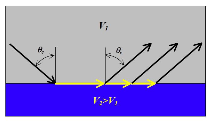
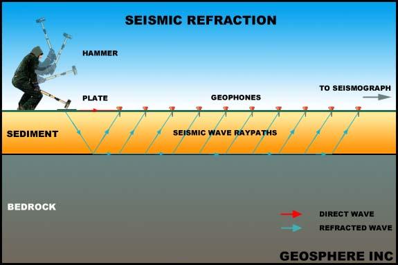
48 WAVES USED IN REFRACTION SURVEY 48
49 The interpreta:on of underground structure from refrac:on results relies on ray- path analysis. The ray path is iden:fied from a travel- Hme graph of arrival :mes vs distance from source. This some:mes called a T- X diagram. 49
50 The interpreta:on technique is basically to inspect the T- X diagram and iden:fy (?guess) the most likely underground structure from which it arises. Values are then picked off the T- X diagram and converted into structure parameters such as depth, etc using the assumed geometry of the ray path. Thus we need to know how T- X diagrams arise. A refrac:on T- X diagram is based on the first arrival at each geophone. This is either picked off the geophone output (manually or in soeware) or is automa:cally recorded by a cut- off :mer. 50

51 SEISMIC RECORD SECTION Source Geophone posi:ons Time (msecs) The T- X diagram is thus a graph of first arrival :mes against distance from source. 51
52 52
53 CRITICAL DISTANCE When the crihcal distance is exceeded, refrac:on occurs and some energy enters layer 2. A refracted ray then travels at V 2 sending return rays back to the surface as it does so. At some point (the cross- over distance) the refracted ray (being the faster) will overtake the direct ray and the return rays will become the first arrivals, despite their longer travel distance. It is these that are now plo<ed on the T- X diagram 53
54 54
55 The T- X diagram thus develops an upper branch due to the refracted ray. This is again a straight line, whose slope is the reciprocal of V 2. There is now an intercept Hme (T 1 ) whose value is determined by the layer 1 thickness and the two veloci:es The intercept :me is an example of a delay Hme sum, composed of the separate :mes taken by the signal to descend to the interface and then to return to the surface. 55
56 INTERCEPT TIME: The intercept :me is given by T = 2z V 2 1 Since, in this case, the ray path is symmetrical, the intercept :me is the sum of two equal delay :mes 2 2 V V V

57 57
58 58
59 59
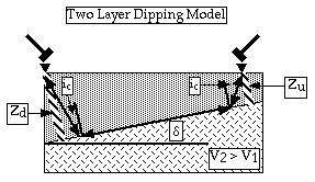
60 Since it is not known in advance whether or not an interface is dipping - and most usually are! - the procedure is always to shoot a profile in both forward and reverse direc:ons (i.e. interchange the shot posi:on with the last geophone and leave the rest in place). The dip will very probably be an apparent dip in the geological sense, since the profile is unlikely to follow the line of true dip. Thus a second, perpendicular, profile is required to allow the true dip to be found. 60
61 IRREGULAR INTERFACE The T- X method smooths off interfaces by fipng a straight line through the data and so irregularies are not analysed. They are however visible as devia:ons from the best fit line and can be analysed using a different method. 61

62 INTERPRETATION Procedure: - First arrivals pick up. - Plot travel time versus distance - Calculate depths to layer interfaces: Z Z 1 2 T T V V 2 V1 2 2Z V 1 V 2 3 V V V V V V V 2 2 TRAVEL TIME (ms) T2 T1 1/V1 1/V2 1/V3 Xc1 Xc2 DISTANCE (m) 62
63 63
 Run inversion Compare calculated to observed data Final layered model result Travel time curves Layered model result Vp = 2750 m/s green picks: second layer red picks: first layer Vp =")
64 Complete analysis process Pick first breaks Select analysis method Time-term inversion gives a quick solution for 2 to 3-layer cases with evident breaks in slope Assign layers Input elevations (if applicable) Run inversion Compare calculated to observed data Final layered model result Travel time curves Layered model result Vp = 2750 m/s green picks: second layer red picks: first layer Vp = 500 m/s Geometrics, Inc September 2009 r4a 15
.")
65 WIDE- ANGLE REFRACTION AND REFLECTION: Interpreta:on of reflected waves (pre- cri:cal and post- cri:cal) and refracted waves in non homogeneous layers with velocity gradient. Rays in a two-layer model: the velocity in the upper layer increases linearly from km/sec, over a thickness of 10 km (gradient 0.15/km/sec/km). The velocity in the lower layer increases linearly from km/sec, over a thickness of 4 km (gradient km/sec/km).
LECTURE 10. Module 3 : Field Tests in Rock 3.6 GEOPHYSICAL INVESTIGATION
 LECTURE 10 3.6 GEOPHYSICAL INVESTIGATION In geophysical methods of site investigation, the application of the principles of physics are used to the study of the ground. The soil/rock have different characteristics
ERTH2020 Introduction to Geophysics The Seismic Method. 1. Basic Concepts in Seismology. 1.1 Seismic Wave Types
 ERTH2020 Introduction to Geophysics The Seismic Method 1. Basic Concepts in Seismology 1.1 Seismic Wave Types Existence of different wave types The existence of different seismic wave types can be understood
Hydrogeophysics - Seismics
 Hydrogeophysics - Seismics Matthias Zillmer EOST-ULP p. 1 Table of contents SH polarized shear waves: Seismic source Case study: porosity of an aquifer Seismic velocities for porous media: The Frenkel-Biot-Gassmann
DOWN-HOLE SEISMIC SURVEY AND VERTICAL ELECTRIC SOUNDINGS RABASKA PROJECT, LÉVIS, QUÉBEC. Presented to :
 DOWN-HOLE SEISMIC SURVEY AND VERTICAL ELECTRIC SOUNDINGS RABASKA PROJECT, LÉVIS, QUÉBEC Presented to : TERRATECH 455, René-Lévesque Blvd. West Montreal, Québec HZ 1Z3 Presented by : GEOPHYSICS GPR INTERNATIONAL
EOS 350 MIDTERM OCT 4, 2013 STUDENT NAME: TEAM #:
 EOS 350 MIDTERM OCT 4, 2013 STUDENT NAME: TEAM #: Some equations which may, or may not, be useful: Distance from sensor to a dipole z ~ x ½, Distance to line of dipoles z ~ 0.75x ½ B = μh, M = κh Seismic
SEISMIC REFRACTION ANALYSIS OF EAST RIVER FLATS MINNEAPOLIS MINNESOTA A THESIS SUBMITTED TO THE FACULTY OF UNIVERSITY OF MINNESOTA AUTUMN HAAGSMA
 SEISMIC REFRACTION ANALYSIS OF EAST RIVER FLATS MINNEAPOLIS MINNESOTA A THESIS SUBMITTED TO THE FACULTY OF UNIVERSITY OF MINNESOTA BY AUTUMN HAAGSMA IN PARTIAL FULFILLMENT OF THE REQUIREMENTS FOR THE DEGREE
Determination of Incompressibility, Elasticity and the Rigidity of Surface Soils and Shallow Sediments from Seismic Wave Velocities
 Journal of Earth Sciences and Geotechnical Engineering, vol. 6, no.1, 2016, 99-111 ISSN: 1792-9040 (print), 1792-9660 (online) Scienpress Ltd, 2016 Determination of Incompressibility, Elasticity and the
Basic principles of the seismic method
 Chapter 2 Basic principles of the seismic method In this chapter we introduce the basic notion of seismic waves. In the earth, seismic waves can propagate as longitudinal (P) or as shear (S) waves. For
Geophysical Site Investigation (Seismic methods) Amit Prashant Indian Institute of Technology Gandhinagar
 Amit Prashant Indian Institute of Technology Gandhinagar") Geophysical Site Investigation (Seismic methods) Amit Prashant Indian Institute of Technology Gandhinagar Short Course on Geotechnical Aspects of Earthquake Engineering 04 08 March, 2013 Seismic Waves
Geophysical Site Investigation (Seismic methods) Amit Prashant Indian Institute of Technology Gandhinagar Short Course on Geotechnical Aspects of Earthquake Engineering 04 08 March, 2013 Seismic Waves
We apply a rock physics analysis to well log data from the North-East Gulf of Mexico
 Rock Physics for Fluid and Porosity Mapping in NE GoM JACK DVORKIN, Stanford University and Rock Solid Images TIM FASNACHT, Anadarko Petroleum Corporation RICHARD UDEN, MAGGIE SMITH, NAUM DERZHI, AND JOEL
Attenuation and dispersion
 Attenuation and dispersion Mechanisms: Absorption (anelastic); Scattering (elastic). P- and S-wave, bulk and shear attenuation Mathematical descriptions Measurement Frequency dependence Velocity dispersion,
LINK BETWEEN ATTENUATION AND VELOCITY DISPERSION
 LINK BETWEEN ATTENUATION AND VELOCITY DISPERSION Jack Dvorkin Stanford University and Rock Solid Images April 25, 2005 SUMMARY In a viscoelastic sample, the causality principle links the attenuation of
Chapter 7: Reflection Seismology Homework Solutions (Jan. 2010)
") Chapter 7: eflection Seismology Homework Solutions (Jan. 200). Why do marine seismic reflection surveys not record (a) S waves? (b) refracted rays? 2 μ a) For ideal fluid, μ=0, thus, v s = = 0 ρ b) eflection
Chapter 7: eflection Seismology Homework Solutions (Jan. 200). Why do marine seismic reflection surveys not record (a) S waves? (b) refracted rays? 2 μ a) For ideal fluid, μ=0, thus, v s = = 0 ρ b) eflection
2.1 Introduction to waves
 Seismic waves 2.1 Introduction to waves A wave: is a periodic disturbance transmits energy through a material no permanent deformation Seismic waves: transmit elastic strain energy (stretching, tearing,
International Journal of Scientific & Engineering Research, Volume 6, Issue 12, December ISSN
 International Journal of Scientific & Engineering Research, Volume 6, Issue 12, December-2015 1052 Determination of Lame s Constants of Surface soils and Shallow Sediments from Seismic Wave Velocities
Acquisition and preliminary analysis of the Castle Mountain shallow VSP dataset
 Castle Mountain shallow VSP Acquisition and preliminary analysis of the Castle Mountain shallow VSP dataset Joe Wong, Henry C. Bland, Kevin W. Hall and Robert R. Stewart ABSTRACT As part of the 2006 geophysics
Near-Surface Seismic Reflection Applications
 Near-Surface Seismic Reflection Applications Don Steeples, The University of Kansas, Lawrence, KS USA Abstract Nonintrusive methods of gaining knowledge about the Earth s subsurface comprise several of
Attenuation and dispersion
 Attenuation and dispersion! Mechanisms: Absorption (inelastic); Scattering (elastic).! Mathematical descriptions! Measurement! Frequency dependence! Dispersion, its relation to attenuation Reading: Sheriff
Compressional and Shear-Wave Velocity Measurements in Unconsolidated Top- Soil in Eket, South-eastern Nigeria.
 Compressional and Shear-Wave Velocity Measurements in Unconsolidated Top- Soil in Eket, South-eastern Nigeria. U.E. Essien, M.Sc. 1 and A.O. Akankpo, M.Sc. 2* 1 Department of Science and Technology, Akwa
Refraction seismic Method
 Refraction seismic Method Field techniques Inversion for refractor velocity, depth, and dip Delay time Interpretation Basic-formula methods Delay-time methods Wavefront reconstruction methods Reading:
Global geophysics and wave propagation
 Global geophysics and wave propagation Reading: Fowler p76 83 Remote sensing Geophysical methods Seismology Gravity and bathymetry Magnetics Heat flow Seismology: Directly samples the physical properties
Effects of Fracture Parameters in an Anisotropy Model on P-Wave Azimuthal Amplitude Responses
 PROC. ITB Eng. Science Vol. 38 B, No. 2, 2006, 159-170 159 Effects of Fracture Parameters in an Anisotropy Model on P-Wave Azimuthal Amplitude Responses Fatkhan Program Studi Teknik Geofisika FIKTM-ITB
7.2.1 Seismic waves. Waves in a mass- spring system
 7..1 Seismic waves Waves in a mass- spring system Acoustic waves in a liquid or gas Seismic waves in a solid Surface waves Wavefronts, rays and geometrical attenuation Amplitude and energy Waves in a mass-
A Petroleum Geologist's Guide to Seismic Reflection
 A Petroleum Geologist's Guide to Seismic Reflection William Ashcroft WILEY-BLACKWELL A John Wiley & Sons, Ltd., Publication Contents Preface Acknowledgements xi xiii Part I Basic topics and 2D interpretation
Elements of 3D Seismology Second Edition
 Elements of 3D Seismology Second Edition Copyright c 1993-2003 All rights reserved Christopher L. Liner Department of Geosciences University of Tulsa August 14, 2003 For David and Samantha And to the memory
Borehole Geophysics. Acoustic logging measurements
 Acoustic logging measurements - Review of basic physics background - Concept of P- and S-wave measurements and logging tools - Tube waves - Seismic imaging - Synthetic seismograms - Field application examples
Seismic Surveying. Dr. Laurent Marescot. Course given at the University of Fribourg (2009) Contact:
 Contact:") Seismic Surveying Dr. Laurent Marescot Course given at the University of Fribourg (2009) Contact: laurent@tomoquest.com 1 Introduction Seismic surveying Investigation based on the propagation of man-made
Seismic Surveying Dr. Laurent Marescot Course given at the University of Fribourg (2009) Contact: laurent@tomoquest.com 1 Introduction Seismic surveying Investigation based on the propagation of man-made
Mass Wasting. Revisit: Erosion, Transportation, and Deposition
 Mass Wasting Revisit: Erosion, Transportation, and Deposition While landslides are a normal part of erosion and surface processes, they can be very destructive to life and property! - Mass wasting: downslope
Sea-bottom shear-wave velocities and mode conversions
 Sea-bottom mode conversions Sea-bottom shear-wave velocities and mode conversions Carlos Rodriguez-Suarez and Robert R. Stewart ABSTRACT Elastic parameters for shallow marine sediments are compiled using
Competing Effect of Pore Fluid and Texture -- Case Study
 Competing Effect of Pore Fluid and Texture -- Case Study Depth (m) Sw Sxo. m Poisson's Ratio.. GOC.1 5 7 8 9 P-Impedance OWC 15 GR.. RHOB.5 1 Saturation...5. 1. 1.5 Vs (km/s).. Poisson's Ratio 5 7 P-Impedance
Integration of Seismic Refraction and 2D Electrical Resistivity in Locating Geological Contact
 Open Journal of Geology, 2013, 3, 7-12 doi:10.4236/ojg.2013.32b002 Published Online April 2013 (http://www.scirp.org/journal/ojg) Integration of Seismic Refraction and 2D Electrical Resistivity in Locating
Sand Control Rock Failure
 Sand Control Rock Failure Why? A bit of Mechanics on rock failure How? Some choices that depend on the rock What is moving? Sand grains? Fines? 3/14/2009 1 Young s Modulus, E Young s Modulus is a material
Multi-station Seismograph Network
 Multi-station Seismograph Network Background page to accompany the animations on the website: IRIS Animations Introduction One seismic station can give information about how far away the earthquake occurred,
ROCK PHYSICS DIAGNOSTICS OF NORTH SEA SANDS: LINK BETWEEN MICROSTRUCTURE AND SEISMIC PROPERTIES ABSTRACT
 ROCK PHYSICS DIAGNOSTICS OF NORTH SEA SANDS: LINK BETWEEN MICROSTRUCTURE AND SEISMIC PROPERTIES PER AVSETH, JACK DVORKIN, AND GARY MAVKO Department of Geophysics, Stanford University, CA 94305-2215, USA
SURFACE WAVE MODELLING USING SEISMIC GROUND RESPONSE ANALYSIS
 43 SURFACE WAVE MODELLING USING SEISMIC GROUND RESPONSE ANALYSIS E John MARSH And Tam J LARKIN SUMMARY This paper presents a study of surface wave characteristics using a two dimensional nonlinear seismic
DEPTH AND VELOCITY ESTIMATES FROM SEISMIC WAVES REFRACTION PATHS AT EBONYI STATE UNIVERSITY STAFF SCHOOL, ABAKALIKI, NIGERIA ABSTRACT
 DEPTH AND VELOCITY ESTIMATES FROM SEISMIC WAVES REFRACTION PATHS AT EBONYI STATE UNIVERSITY STAFF SCHOOL, ABAKALIKI, NIGERIA Agha, S. O. Dept. of Industrial Physics Ebonyi State University Abakaliki, NIGERIA
Finite difference elastic modeling of the topography and the weathering layer
 Finite difference elastic modeling of the topography and the weathering layer Saul E. Guevara and Gary F. Margrave ABSTRACT Finite difference 2D elastic modeling is used to study characteristics of the
6298 Stress induced azimuthally anisotropic reservoir - AVO modeling
 6298 Stress induced azimuthally anisotropic reservoir - AVO modeling M. Brajanovski* (Curtin University of Technology), B. Gurevich (Curtin University of Technology), D. Nadri (CSIRO) & M. Urosevic (Curtin
Methane hydrate rock physics models for the Blake Outer Ridge
 Stanford Exploration Project, Report 80, May 15, 2001, pages 1 307 Methane hydrate rock physics models for the Blake Outer Ridge Christine Ecker 1 ABSTRACT Seismic analyses of methane hydrate data from
An empirical method for estimation of anisotropic parameters in clastic rocks
 An empirical method for estimation of anisotropic parameters in clastic rocks YONGYI LI, Paradigm Geophysical, Calgary, Alberta, Canada Clastic sediments, particularly shale, exhibit transverse isotropic
ANGLE-DEPENDENT TOMOSTATICS. Abstract
 ANGLE-DEPENDENT TOMOSTATICS Lindsay M. Mayer, Kansas Geological Survey, University of Kansas, Lawrence, KS Richard D. Miller, Kansas Geological Survey, University of Kansas, Lawrence, KS Julian Ivanov,
Site Characterization & Hydrogeophysics
 Site Characterization & Hydrogeophysics (Source: Matthew Becker, California State University) Site Characterization Definition: quantitative description of the hydraulic, geologic, and chemical properties
Groundwater Sustainability at Wadi Al Bih Dam, Ras El Khaimah, United Arab Emirates (UAE) using Geophysical methods
 using Geophysical methods") Groundwater Sustainability at Wadi Al Bih Dam, Ras El Khaimah, United Arab Emirates (UAE) using Geophysical methods Ahmed Murad, Amir Gabr, Saber Mahmoud, Hasan Arman & Abdulla Al Dhuhoori Geology Department
Groundwater Sustainability at Wadi Al Bih Dam, Ras El Khaimah, United Arab Emirates (UAE) using Geophysical methods Ahmed Murad, Amir Gabr, Saber Mahmoud, Hasan Arman & Abdulla Al Dhuhoori Geology Department
A. V T = 1 B. Ms = 1 C. Vs = 1 D. Vv = 1
 Geology and Soil Mechanics 55401 /1A (2002-2003) Mark the best answer on the multiple choice answer sheet. 1. Soil mechanics is the application of hydraulics, geology and mechanics to problems relating
Geology and Soil Mechanics /1A ( ) Mark the best answer on the multiple choice answer sheet.
 Mark the best answer on the multiple choice answer sheet.") Geology and Soil Mechanics 55401 /1A (2003-2004) Mark the best answer on the multiple choice answer sheet. 1. Soil mechanics is the application of hydraulics, geology and mechanics to problems relating
Geology and Soil Mechanics 55401 /1A (2003-2004) Mark the best answer on the multiple choice answer sheet. 1. Soil mechanics is the application of hydraulics, geology and mechanics to problems relating
PART A: Short-answer questions (50%; each worth 2%)
") PART A: Short-answer questions (50%; each worth 2%) Your answers should be brief (just a few words) and may be written on these pages if you wish. Remember to hand these pages in with your other exam pages!
PART A: Short-answer questions (50%; each worth 2%) Your answers should be brief (just a few words) and may be written on these pages if you wish. Remember to hand these pages in with your other exam pages!
Downloaded 11/20/12 to Redistribution subject to SEG license or copyright; see Terms of Use at
 AVO crossplot analysis in unconsolidated sediments containing gas hydrate and free gas: Green Canyon 955, Gulf of Mexico Zijian Zhang* 1, Daniel R. McConnell 1, De-hua Han 2 1 Fugro GeoConsulting, Inc.,
SEISMIC SURVEY METHODS
 SEISMIC SURVEY METHODS Seismic methods Seismic surveys are used in geology and geotechnical engineering to: a) define the depth of the bedrock; b) investigate the landslide areas, c) check the structural
A Case Study on Simulation of Seismic Reflections for 4C Ocean Bottom Seismometer Data in Anisotropic Media Using Gas Hydrate Model
 A Case Study on Simulation of Seismic Reflections for 4C Ocean Bottom Seismometer Data in Anisotropic Media Using Gas Hydrate Model Summary P. Prasada Rao*, N. K. Thakur 1, Sanjeev Rajput 2 National Geophysical
A Constitutive Framework for the Numerical Analysis of Organic Soils and Directionally Dependent Materials
 Dublin, October 2010 A Constitutive Framework for the Numerical Analysis of Organic Soils and Directionally Dependent Materials FracMan Technology Group Dr Mark Cottrell Presentation Outline Some Physical
P- and S-Wave Velocity Measurements and Pressure Sensitivity Analysis of AVA Response
 P- and S-Wave Velocity Measurements and Pressure Sensitivity Analysis of AVA Response Tiewei He* University of Alberta, Edmonton, Alberta, Canada tieweihe@phys.ualberta.ca and Douglas Schmitt University
CENTER FOR INFRASTRUCTURE ENGINEERING STUDIES
 1 CENTER FOR INFRASTRUCTURE ENGINEERING STUDIES Acquisition of an Engineering Seismograph By Dr. Neil Anderson UTC RE116 University Transportation Center Program at The University of Missouri-Rolla 2 Disclaimer
Seismic Velocity Measurements at Expanded Seismic Network Sites
 UK/KRCEE Doc #: P8.3 2005 Seismic Velocity Measurements at Expanded Seismic Network Sites Prepared by Kentucky Research Consortium for Energy and Environment 233 Mining and Minerals Building University
FUNDAMENTALS OF SEISMIC EXPLORATION FOR HYDROCARBON
 FUNDAMENTALS OF SEISMIC EXPLORATION FOR HYDROCARBON Instructor : Kumar Ramachandran 10 14 July 2017 Jakarta The course is aimed at teaching the physical concepts involved in the application of seismic
PHYSICO-MECHANICAL PROPERTIES OF ROCKS LECTURE 2. Contents
 PHYSICO-MECHANICAL PROPERTIES OF ROCKS LECTURE 2 Contents 2.1 Introduction 2.2 Rock coring and logging 2.3 Physico-mechanical properties 2.3.1 Physical Properties 2.3.1.1 Density, unit weight and specific
SENSITIVITY ANALYSIS OF AMPLITUDE VARIATION WITH OFFSET (AVO) IN FRACTURED MEDIA
 IN FRACTURED MEDIA") SENSITIVITY ANALYSIS OF AMPLITUDE VARIATION WITH OFFSET AVO) IN FRACTURED MEDIA Mary L. Krasovec, William L. Rodi, and M. Nafi Toksoz Earth Resources Laboratory Department of Earth, Atmospheric, and Planetary
SENSITIVITY ANALYSIS OF AMPLITUDE VARIATION WITH OFFSET AVO) IN FRACTURED MEDIA Mary L. Krasovec, William L. Rodi, and M. Nafi Toksoz Earth Resources Laboratory Department of Earth, Atmospheric, and Planetary
D scattering of obliquely incident Rayleigh waves by a saturated alluvial valley in a layered half-space
 1842. 3-D scattering of obliquely incident Rayleigh waves by a saturated alluvial valley in a layered half-space Zhenning Ba 1, Jianwen Liang 2 Department of Civil Engineering, Tianjin University, Tianjin
Seismic Reflection Imaging across the Johnson Ranch, Valley County, Idaho
 Seismic Reflection Imaging across the Johnson Ranch, Valley County, Idaho Report Prepared for the Skyline Corporation Lee M. Liberty Center for Geophysical Investigation of the Shallow Subsurface (CGISS)
Lima Project: Seismic Refraction and Resistivity Survey. Alten du Plessis Global Geophysical
 Lima Project: Seismic Refraction and Resistivity Survey Alten du Plessis Global Geophysical Report no 0706/2006 18 December 2006 Lima Project: Seismic Refraction and Resistivity Survey by Alten du Plessis
A scale/resolution problem
 Near Surface 2005 September 4-7, 2005, Palermo Italy WORKSHOP on Hydrogeophysics a tool for sustainable use of groundwater resources Integrated Seismic and GPR characterization of fractured rocks Pipan,
How to Identify and Properly Classify Drill Cuttings
 How to Identify and Properly Classify Drill Cuttings (Creating Useful Borehole Logs) Dave Larson Hydrogeology and Geophysics Section Accurate information about the borehole location and a careful description
Micro Seismic Hazard Analysis
 Micro Seismic Hazard Analysis Mark van der Meijde INTERNATIONAL INSTITUTE FOR GEO-INFORMATION SCIENCE AND EARTH OBSERVATION Overview Site effects Soft ground effect Topographic effect Liquefaction Methods
Welcome back. So, in the last lecture we were seeing or we were discussing about the CU test. (Refer Slide Time: 00:22)
") Geology and Soil Mechanics Prof. P. Ghosh Department of Civil Engineering Indian Institute of Technology Kanpur Lecture - 43 Shear Strength of Soils Keywords: Triaxial shear test, unconsolidated undrained
Geology and Soil Mechanics Prof. P. Ghosh Department of Civil Engineering Indian Institute of Technology Kanpur Lecture - 43 Shear Strength of Soils Keywords: Triaxial shear test, unconsolidated undrained
Towards Modelling Elastic and Viscoelastic Seismic Wave Propagation in Boreholes
 Towards Modelling Elastic and Viscoelastic Seismic Wave Propagation in Boreholes NA WANG, DONG SHI, BERND MILKEREIT Department of Physics, University of Toronto, Toronto, Canada M5S 1A7 Summary We are
SUMMARY INTRODUCTION EXPERIMENTAL PROCEDURE
 Frequency dependent elastic properties and attenuation in heavy-oil sands: comparison between measured and modeled data Agnibha Das, and Michael Batzle, Colorado School of Mines SUMMARY We have measured
Seismic Refraction Investigation at a Radioactive Waste Disposal Site
 Geosciences 2012, 2(2): 7-13 DOI: 10.5923/j.geo.20120202.02 Seismic Refraction Investigation at a Radioactive Waste Disposal Site A. M. A Dawood 1,*, T. T. Akiti 2, E. T. Glover 1 1 National Radioactive
Upscaling Aspects of Spatial Scaling
 Aspects of Spatial Scaling 288 We need to relate measurements at different scales Lab Logs Crosswell VSP Surface Seismic How does laboratory rock physics apply to the field? frequency differences sample
Crosswell tomography imaging of the permeability structure within a sandstone oil field.
 Crosswell tomography imaging of the permeability structure within a sandstone oil field. Tokuo Yamamoto (1), and Junichi Sakakibara (2) (1) University of Miami and Yamamoto Engineering Corporation, (2)
Linearized AVO and Poroelasticity for HRS9. Brian Russell, Dan Hampson and David Gray 2011
 Linearized AO and oroelasticity for HR9 Brian Russell, Dan Hampson and David Gray 0 Introduction In this talk, we combine the linearized Amplitude ariations with Offset (AO) technique with the Biot-Gassmann
Time-lapse seismic modelling for Pikes Peak field
 Time-lapse seismic modelling for Pikes Peak field Ying Zou*, Laurence R. Bentley and Laurence R. Lines University of Calgary, 2500 University Dr, NW, Calgary, AB, T2N 1N4 zou@geo.ucalgary.ca ABSTRACT Predicting
Applying Seismic Refraction Method in Depicting Geological Contact at Bukit Bunuh, Lenggong, Perak, Malaysia
 2012 International Conference on Geological and Environmental Sciences IPCBEE vol.3 6(2012) (2012)IACSIT Press, Singapoore Applying Seismic Refraction Method in Depicting Geological Contact at Bukit Bunuh,
Ch 4a Stress, Strain and Shearing
 Ch. 4a - Stress, Strain, Shearing Page 1 Ch 4a Stress, Strain and Shearing Reading Assignment Ch. 4a Lecture Notes Sections 4.1-4.3 (Salgado) Other Materials Handout 4 Homework Assignment 3 Problems 4-13,
Tu P8 08 Modified Anisotropic Walton Model for Consolidated Siliciclastic Rocks: Case Study of Velocity Anisotropy Modelling in a Barents Sea Well
 Tu P8 08 Modified Anisotropic Walton Model for Consolidated Siliciclastic Rocks: Case Study of Velocity Anisotropy Modelling in a Barents Sea Well Y. Zhou (Rock Solid Images), F. Ruiz (Repsol), M. Ellis*
Refraction analysis of the Blackfoot 2D-3C data
 Refraction analysis of the Blackfoot 2D-3C data Refraction analysis of the Blackfoot 2D-3C data Jocelyn Dufour, and Don C. Lawton ABSTRACT A three-component 2D seismic line was acquired in the Blackfoot
Geotechnical verification of impact compaction
 PII-73 Geotechnical verification of impact compaction P. J. Waddell1, R. A. Moyle2 & R. J. Whiteley1 1 2 Coffey Geotechnics, Sydney, Australia Coffey Geotechnics, Harrogate, UK Abstract Remediation of
An investigation of the free surface effect
 An investigation of the free surface effect Nasser S. Hamarbitan and Gary F. Margrave, An investigation of the free surface effect ABSTRACT When P and S seismic waves are incident on a solid-air interface
Seismic tests at Southern Ute Nation coal fire site
 Seismic tests at Southern Ute Nation coal fire site Sjoerd de Ridder and Seth S. Haines ABSTRACT We conducted a near surface seismic test at the Southern Ute Nation coal fire site near Durango, CO. The
Integrating rock physics and full elastic modeling for reservoir characterization Mosab Nasser and John B. Sinton*, Maersk Oil Houston Inc.
 Integrating rock physics and full elastic modeling for reservoir characterization Mosab Nasser and John B. Sinton*, Maersk Oil Houston Inc. Summary Rock physics establishes the link between reservoir properties,
Module 1 : Site Exploration and Geotechnical Investigation
 Objectives In this section you will learn the following Displacement borings Wash boring Auger boring Rotary drilling Percussion drilling Continuous sampling Boring methods of exploration The boring methods
Geotechnical Properties of Soil
 Geotechnical Properties of Soil 1 Soil Texture Particle size, shape and size distribution Coarse-textured (Gravel, Sand) Fine-textured (Silt, Clay) Visibility by the naked eye (0.05 mm is the approximate
MOUNT POLLEY MINING CORPORATION TECHNICAL REPORT ON MULTI-ELECTRODE RESISTIVITY AND SEISMIC REFRACTION SURVEYS MOUNT POLLEY TAILINGS DAM PROJECT
 MOUNT PLEY MINING CORPORATION TECHNICAL REPORT ON MULTI-ELECTRODE RESISTIVITY AND SEISMIC REFRACTION SURVEYS MOUNT PLEY TAILINGS DAM PROJECT LIKELY, B.C. by Claudia Krumbiegel, M.Sc. Cliff Candy, P.Geo.
Introduction to Engineering Seismology Lecture 6
 Lecture 6: Theory of wave propagation; Seismic waves, body and surface waves. Topics How seismic waves are produced? Wave and its Properties Wave Propagation Types of Seismic Waves Compressional or P-Waves
ROCK PHYSICS MODELING FOR LITHOLOGY PREDICTION USING HERTZ- MINDLIN THEORY
 ROCK PHYSICS MODELING FOR LITHOLOGY PREDICTION USING HERTZ- MINDLIN THEORY Ida Ayu PURNAMASARI*, Hilfan KHAIRY, Abdelazis Lotfy ABDELDAYEM Geoscience and Petroleum Engineering Department Universiti Teknologi
Estimating rock porosity and fluid saturation using only seismic velocities
 Stanford Exploration Project, Report, October 5, 999, pages 4 57 Estimating rock porosity and fluid saturation using only seismic velocities James G. Berryman, Patricia A. Berge, and Brian P. Bonner keywords:
Ground-Water Exploration in the Worthington Area of Nobles County: Summary of Seismic Data and Recent Test Drilling Results
 Ground-Water Exploration in the Worthington Area of Nobles County: Summary of Seismic Data and Recent Test Drilling Results Jim Berg and Todd Petersen Geophysicists, DNR Waters January 2000 Table of Contents
Techniques for determining the structure and properties of permafrost
 Stanford Exploration Project, Report 80, May 15, 2001, pages 1 404 Techniques for determining the structure and properties of permafrost Ray Abma 1 ABSTRACT Several methods for predicting the relationship
Global Seismology Chapter 4
 Global Seismology Chapter 4 Earthquake: an event of ground shaking usually caused by the rupturing of a fault within the Earth. Who studies Earthquakes? Seismologists waves Geophysicists Mechanics Geodesy
Reflection Seismic Method
 Reflection Seismic Method Data and Image sort orders; Seismic Impedance; -D field acquisition geometries; CMP binning and fold; Resolution, Stacking charts; Normal Moveout and correction for it; Stacking;
Rock physics of a gas hydrate reservoir. Gas hydrates are solids composed of a hydrogen-bonded ROUND TABLE
 ROUND TABLE Rock physics of a gas hydrate reservoir JACK DVORKIN and AMOS NUR, Stanford University, California, U.S. RICHARD UDEN and TURHAN TANER, Rock Solid Images, Houston, Texas, U.S. Gas hydrates
Soil Behaviour in Earthquake Geotechnics
 Soil Behaviour in Earthquake Geotechnics KENJI ISHIHARA Department of Civil Engineering Science University of Tokyo This publication was supported by a generous donation from the Daido Life Foundation
Hydraulic properties of porous media
 PART 5 Hydraulic properties of porous media Porosity Definition: Void space: n V void /V total total porosity e V void /V solid Primary porosity - between grains Secondary porosity - fracture or solution
Mandatory Assignment 2013 INF-GEO4310
 Mandatory Assignment 2013 INF-GEO4310 Deadline for submission: 12-Nov-2013 e-mail the answers in one pdf file to vikashp@ifi.uio.no Part I: Multiple choice questions Multiple choice geometrical optics
2011 SEG SEG San Antonio 2011 Annual Meeting 771. Summary. Method
 Geological Parameters Effecting Controlled-Source Electromagnetic Feasibility: A North Sea Sand Reservoir Example Michelle Ellis and Robert Keirstead, RSI Summary Seismic and electromagnetic data measure
ERTH2020 Tutorial Exercise 1: Basic Maths Revision - Answers
 ERTH2020 Tutorial 1 Maths Revision Page 1 ERTH2020 Tutorial Exercise 1: Basic Maths Revision - Answers The purpose of this document is to provide answers - not working. Note that in an exam situation you
A Study of Uphole to Determine the Shooting Medium for Seismic Reflection Survey at Himalayan Foot Hill Area
 A Study of Uphole to Determine the Shooting Medium for Seismic Reflection Survey at Himalayan Foot Hill Area Summary Binode Chetia Frontier Basins, ONGC, Dehradun E-mail: chetia_binode@ongc.co.in Acquiring
Soil Properties - II
 Soil Properties - II Amit Prashant Indian Institute of Technology andhinagar Short Course on eotechnical Aspects of Earthquake Engineering 04 08 March, 2013 Seismic Waves Earthquake Rock Near the ground
Faults. Strike-slip fault. Normal fault. Thrust fault
 Faults Strike-slip fault Normal fault Thrust fault Fault any surface or narrow zone with visible shear displacement along the zone Normal fault Strike-slip fault Reverse fault Thrust fault
INTRODUCTION TO LOGGING TOOLS
 BY: MUHAMMAD ZAHID INTRODUCTION TO LOGGING TOOLS 1- SPONTANEOUS POTENTIAL (SP) The Spontaneous potential survey, (sp) was one of the first measurements, which was carried out, in a well bore. The SP log
Amplitude variation with offset AVO. and. Direct Hydrocarbon Indicators DHI. Reflection at vertical incidence. Reflection at oblique incidence
 Amplitude variation with offset AVO and Direct Hydrocarbon Indicators DHI Reflection at vertical incidence Reflection coefficient R(p) c α 1 S wavespeed β 1 density ρ 1 α 2 S wavespeed β 2 density ρ 2
II Pedologic classifica>on schemes
 SOILS (06) I Main Topics A Pedologic classifica>on schemes B Engineering classifica>on schemes C Proper>es of engineering soils D Effec>ve stress, pore pressure, and total stress E Consolida>on 2/2/15