fregonruleco. 1 U.S.A. 2
|
|
|
- Jocelin Webb
- 5 years ago
- Views:
Transcription


1 3 5 fregonruleco. 1 U.S.A. 2

2 IL6cr Qojl ^^\ ISGS CONTRACT/GRANT REPORT GEOPHYSICAL STUDIES AT THE SHEFFIELD LOW-LEVEL RADIOACTIVE WASTE DISPOSAL FACILITY TO EVALUATE POTENTIAL PATHWAYS FOR THE ESCAPE OF CONTAMINANTS Paul C. Heigold Timothy H. Larson Illinois Department of Energy and Natural Resources STATE GEOLOGICAL SURVEY DIVISION


3 Heigold, Paul C. Geophysical studies at the Sheffield low-level radioactive waste disposal facility to evaluate potential pathways for the escape of contaminants / Paul C. Heigold, Timothy H. Larson. -- Champaign, ill. Illinois State Geological Survey, p. ; 28 cm. -- (Illinois-Geological Survey. Contract/Grant report ; ) "... funds provided by the Illinois Department of Nuclear Safety." 1. Radioactive waste disposal-lllinois-bureau County. 2. Water, Underground-Pollution. 3. Geophysical exploration. I. Larson, Timothy H. II. Illinois Department of Nuclear Safety. III. Series. Printed by authority of the State of Illinois/1985/200 > STATE GEOLOGICAL SURVEY


4 ISGS CONTRACT/GRANT REPORT GEOPHYSICAL STUDIES AT THE SHEFFIELD LOW-LEVEL RADIOACTIVE WASTE DISPOSAL FACILITY TO EVALUATE POTENTIAL PATHWAYS FOR THE ESCAPE OF CONTAMINANTS Paul C. Heigoid Timothy H. Larson S v &UG The study upon which this report is based was partly supported by funds provided by the Illinois Department of Nuclear Safety. ILLINOIS STATE GEOLOGICAL SURVEY Morris W. Leighton, Chief Natural Resources Building 615 East Peabody Drive Champaign, Illinois 61820


5 Digitized by the Internet Archive in 2012 with funding from University of Illinois Urbana-Champaign


6 1 1 5 ABSTRACT 1 INTRODUCTION 1 GEOLOGY 2 GEOPHYSICAL METHODS RESULTS OF SURVEYS WESTERN SIDE 3 EASTERN SIDE 4 NORTHERN SIDE 5 CONCLUSIONS 7 REFERENCES 23 FIGURES Figure 1 Location of the Sheffield area of Bureau County, Illinois, Section 26, T. 16 N., R. 6 E. 1 Figure 2 Topographic map of Sheffield low-level radioactive waste (LLRW) disposal site 8 Figure 3 Quaternary classification system in relation to rock stratigraphic classification system 9 Figure 4 Bedrock topography of the Sheffield LLRW disposal site and adjacent area 10 Figure 5a Elevation of water table surface at the Sheffield LLRW disposal site 1 Figure 5b Elevation of water tables at the Sheffield LLRW disposal site 12 Figure 6 Location of vertical electric sounding (VES) profiles around the Sheffield LLRW disposal site 13 Figure 7 Location of the shallow geothermic surveys around the Sheffield LLRW disposal site 14 Figure 8 Location of wells, borings, trenches, and tunnel at the Sheffield LLRW disposal site 1 Figure 9 Geoelectric section obtained by automatic inversion of VES profile Figure 10 Soil temperatures along northern portion of the western side of the Sheffield LLRW disposal site 17 Figure 1 Soil temperatures along the southern portion of the western side of the Sheffield LLRW disposal site 17 Figure 12 Geoelectric sections obtained by automatic inversion of VES curves associated with VES profiles 1, 2, and 3 18 Figure 13 Soil temperatures along the southern side of the Sheffield LLRW disposal site 19 Figure 14 Geoelectric sections obtained on automatic inversion of VES curves associated with VES profiles 4, 5, 6, and 7 20 Figure 15 Geoelectric sections obtained by automatic inversion of VES profiles 8 and Figure 16 Soil temperatures along the northern side of the Sheffield LLRW disposal site 22

7


8 ABSTRACT Surficial electrical resistivity and shallow geothermic surveys were conducted along the western, southern, and northern sides of the Sheffield low-level radioactive waste-disposal site in Bureau County, Illinois. The purpose of these surveys was to find and delineate the boundaries of waterbearing, coarse-grained glacial deposits that could be conduits for contaminated groundwater leaving the waste-disposal site. These surveys did not indicate the presence of any previously unknown coarse-grained deposits capable of serving as pathways for contaminants; however, they did confirm the existence of a buried bedrock channel containing sands of the Toulon Member of the Glasford Formation. Located near the eastern end of the northern boundary of the LLRW disposal site, this channel may be related to a previously discovered pathway for contaminants moving eastward from the disposal site. INTRODUCTION The Sheffield low-level radioactive waste (LLRW) disposal site was closed in April The site was located in southwestern Bureau County, Illinois (Sec. 26, T. 16 N., R. 6 E.) (figs. 1 and 2). Detailed monitoring has indicated the presence of small amounts of tritium in a few observation wells bordering the site. In earlier efforts to find and delineate pathways for tritiated groundwater leaving the disposal site (Larson, 1981; Larson, Gilkeson, and Heigold, 1983; Heigold, Gilkeson, and Larson, 1983), geophysicists at the Illinois State Geological Survey conducted surficial electrical resistivity and shallow geothermic surveys to the east of the disposal site. In one area, tritiated groundwater was being transported away from the disposal site through a shallow, coarse-grained deposit; its boundaries were delineated. In another area, a shallow geothermic survey indicated that a well in which small amounts of tritium had been detected was located with a narrow reentrant on the sloping shale bedrock surface a pathway for tritiated groundwater to leave the disposal site. Figure 1. Location of the Sheffield area of Bureau County, Illinois, Section 26, T. 16 N., R.6 E.

 is summarized in figure 3.")
9 In a further effort to find and delineate the pathways taken by contaminated groundwater leaving the LLRW disposal site, more reconnaissance surficial electrical resistivity and shallow geothermic surveys have been conducted along the western, southern, and northern sides of the LLRW disposal site. The results of these surveys are the subject of this report. GEOLOGY In the study area unconsolidated Wisconsinan and Illinoian glacial sediments rest unconformably on Pennsyl vanian bedrock. The Pleistocene stratigraphy of the Sheffield LLRW disposal site described by Foster and Erickson (1980) is summarized in figure 3. Essentially, the Pleistocene units consist of variable amounts of Peoria Loess overlying one to three members of the Glasford Formation. The Toulon Member of the Glasford Formation is a unit of particular interest. It is an outwash deposit that varies considerably in thickness and consists generally of poorly sorted, pebbly sand that in places grades into either clean sand or clean gravel. Earlier exploratory work found that the Toulon Member formed a conduit for contaminants leaving the eastern side of the LLRW disposal site. The bedrock surface consists of shale of the Carbondale Formation (Willman et al., 1975). The bedrock topography of the Sheffield site and adjacent areas is shown in figure 4. Both this map and the map (fig. 5a) showing the elevation of the water-table surface at the Sheffield site indicate that two buried bedrock channels control the direction of groundwater flow away from the site. One channel directs flow toward the northeast, the other to the southeast. A more recent map showing the elevation of the water-table surface at the Sheffield site (fig. 5b) presents a different configuration of the water-table surface. Figure 5b does not indicate any influence of the buried bedrock channel on the elevation of the water-table surface on the eastern end of the northern boundary of the LLRW disposal site. This map incorporates recently acquired water-table data east of the LLRW disposal site. In our opinion, however, these newly acquired data do not provide sufficient information to preclude previous interpretations of the water-table configuration on the eastern end of the northern boundary of the LLRW disposal site. GEOPHYSICAL METHODS Surficial electrical resistivity surveying on the western, southern, and northern sides of the LLRW disposal site consisted of 13 vertical electrical sounding (VES) profiles (fig. 6). The Wenner electrode configuration was employed in all VES profiles. This electrode configuration permits more nearsurface earth materials to be sampled at each resistivity station than with the more focused Schlumberger electrode configuration. This was desirable because the number and location of VES profiles were limited by dense vegetation, steeply sloping terrain, and engineered structures. Efforts were
.")
, below the depth affected by diurnal temperature variations. Two separate surveys covered essentially the same areas.")
10 made to locate VES profiles in places where the electrodes could be kept at approximately the same elevation. The VES data were collected with a Bison 2350B resistivity meter and interpreted with the aid of the automatic inversion program of Zohdy and Bisdorf (1975). Shallow geothermic surveying on the western, southern, and northern sides of the LLRW disposal site consisted of a network of soil temperature measurements made 1 meter below land surface (fig. 7), below the depth affected by diurnal temperature variations. Two separate surveys covered essentially the same areas. One survey was conducted during the winter (March 13, 1984) and the second during the summer (July 11, 1984). Shallow aquifers often form heat sources in the winter and heat sinks in the summer, thus influencing the temperature of the soil beyond the effects of heat originating at the earth's surface or from the earth's interior (Cartwright, 1968). Unfortunately, field conditions during the winter survey were unfavorable and the data were unreliable. Subsequent discussion of the shallow geothermic data will deal only with the summer survey. Just as with the electrical resistivity surveying, the extent of the geothermic surveying was severely restricted by the dense vegetation and engineered structures around the LLRW disposal site. All soil temperatures were measured with a Cole-Palmer digital thermometer (Model K ) and Cole-Palmer general thermistor probes (Model K ). RESULTS OF SURVEYS: WESTERN SIDE The western side of the LLRW disposal site provided little opportunity to conduct a meaningful electrical resistivity survey. In the narrow area between the LLRW disposal site and a chemical waste disposal site located immediately west of the LLRW site, steep terrain and dense vegetation allowed only two VES profiles to be run (fig. 6). The VES curve associated with VES profile 9, centered near test boring 150 (fig. 8), correlated well with the results of sampling at this test boring. Low apparent resistivities in this profile corresponded to a thin section of silty glacial deposits resting on shale bedrock. VES profile 10 was located in a topographic low near the southwestern corner of the LLRW disposal site between test borings 126 and 127 (figs. 6 and 8). The geoelectric section obtained by the inversion of the VES curve from VES profile 10 (fig. 9) indicates that a layer of fine-grained glacial sediments (with a resistivity of 70 to 85 ohm- feet) overlies slightly coarser-grained glacial deposits (185 ohm-feet) above shale bedrock. Although 185 ohm- feet is a relatively high resistivity value, it is not normally associated with deposits having significantly large hydraulic conductivities. This result confirmed the findings of test borings 126 and 127: in this area there is a thin, discontinuous layer (0 to 5 feet thick) of sand and gravel within the glacial deposits. The summer geothermic survey on the western side of the LLRW site consisted of a single line of soil temperature measurements along the northern portion of the west boundary fence, and two parallel lines of soil temperature
 do not show abrupt lateral changes that could be related to lithologic changes in the near-surface glacial sediments.")

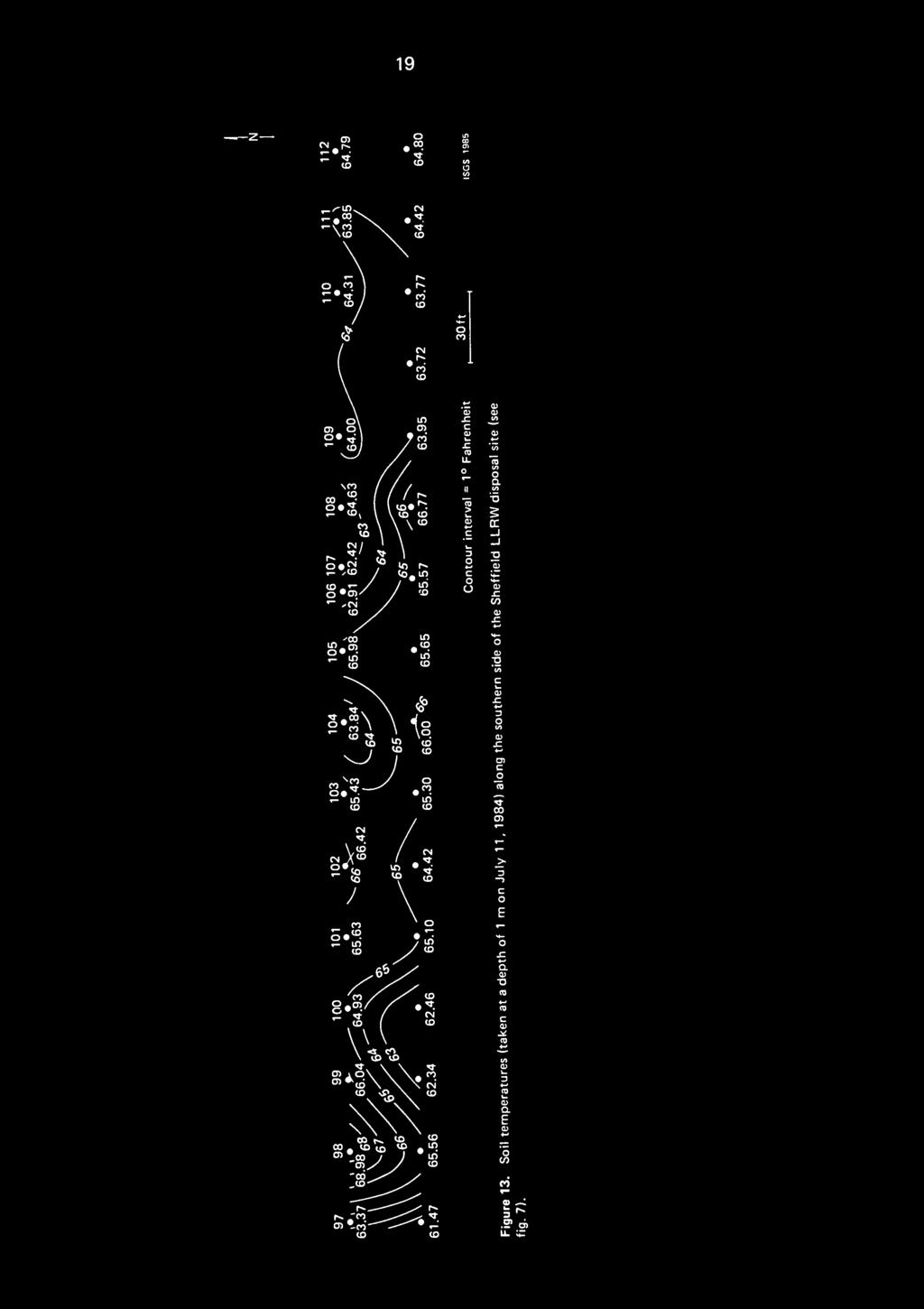
11 measurements along the southern end of the west boundary fence (fig. 7). The southern geothermic lines were separated from this boundary fence by a strip of dense vegetation. The soil temperatures along all the lines (figs. 10 and 11) do not show abrupt lateral changes that could be related to lithologic changes in the near-surface glacial sediments. On the contrary, the soil temperatures correlate positively with surface elevation. This phenomenon is probably due to the fact that the water table is deeper at higher topographic elevations and that areas of higher topographic elevation generally receive more solar radiation. Although contributions to soil temperatures of geothermal heat from the earth's interior are negatively correlated with surface elevation, this factor is negligible in comparison to the othe^ factors mentioned. In the southern portion of this survey along the western boundary of the site, soil temperatures along the line closer to the fence were generally cooler than those along the line farther from the fence. This does not indicate an underlying change in lithology, but the effect of vegetation on soil temperatures. The dense vegetation growing along the fence provides partial shade to adjacent area; root structures hold moisture in the soil. In summary, although the logs of test borings 126, 102, 511, and 122 along the western side of the LLRW disposal site (fig. 8) all show the presence of sand deposits, these deposits do not appear to be large enough or to have sufficient great hydraulic conductivity to serve as conduits for contaminants leaving the LLRW disposal site. Moreover, water-table elevations in and around the LLRW disposal site (fig. 5) suggest that groundwater moves toward the LLRW disposal site from the west. RESULTS OF SURVEYS: SOUTHERN SIDE On the southern side of the LLRW disposal site (fig. 6), three VES profiles were arranged in a line just outside of and parallel to the boundary fence, on a hillside slopeing steeply to the south. The bedrock topography map (fig. 4) shows that the three VES profiles are located on an east-west trending bedrock high. In test boring 128 near the center stake of VES profile 1, the unconsolidated glacial deposits are 31 feet thick (fig. 8); samples indicate that the glacial sediments are well-drained, fine-grained loess and till resting on shale bedrock. The geoelectric sections obtained from the inversions of the VES curves associated with VES profiles 1, 2, and 3 (figs. 6 and 12) are \/ery similar. A thin, low-resistivity layer at the surface is underlain by a higher resistivity layer, which in turn is underlain by another low resistivity layer. The two uppermost resistivity layers correspond to two layers of unsaturated, fine-grained deposits; the lower of these two layers is slightly coarser grained. The shallow geothermic survey in July 1984 consisted of two lines of soil temperature measurements made just outside of and parallel to the boundary fence on the southern side of the LLRW disposal site (fig. 7). The temper-

, provide drainage away from the site.")
12 ature data along these lines (fig. 13) probably reflect lithologic changes in unconsolidated glacial deposits. Shallow, coarse, well drained sediments are typically associated with higher soil temperatures during the summer months; thus the higher temperature values observed near the western end of the survey lines strongly suggest the presence of such deposits. Samples from test boring 120 (fig. 8) west of the line of tempeature measurements indicate that the glacial till contains sand and gravel. The southeast corner of the LLRW disposal site is particularly interesting: both the surface topography and a buried bedrock channel (figs. 2 and 4), provide drainage away from the site. A pebbly, well sorted sand unit over 7 feet thick was encountered in test boring 525 (fig. 8) and attributed to the Wisconsinan Henry Formation. However, test borings indicate that sand of the Toulon Member of the Glasford Formation, which forms a conduit for contaminants leaving the eastern side of the LLRW disposal site (Larson, Gilkeson, and Heigold, 1983), is absent in this area. Although the sand of the Henry Formation near the southeast corner of the LLRW disposal site is similar in texture to sand of the Toulon Member of the Glasford Formation east of the disposal site, the Henry Formation is younger and is unrelated to the Toulon Member (fig. 3). Unfortunately, rough terrain and dense vegetation did not allow VES profiles and soil temperature measurements to be located along the eastern end of the southern boundary of the LLRW disposal site. In summary, geophysical data gathered in accessible areas on the southern side of the LLRW disposal site did not indicate the presence of shallow glacial deposits capable of serving as significant pathways for contaminant transport in those areas. RESULTS OF SURVEYS: NORTHERN SIDE Four VES profiles were located in a line just outside of, and parallel to, the fence on the northern side of the LLRW disposal site (fig. 6). Inversion of the VES curves associated with these VES profiles yielded geoelectric sections (fig. 14) whose resistivities and thicknesses are consistent with the results of sampling in test borings 513, 515, and 514 (fig. 8) along the northern boundary fence. Within the geoelectric sections, a thin, low-resistivity surface layer appears to correspond to a thin layer of clayey silt. A second, higher-resistivity layer below corresponds to a slightly coarser, but still fine-grained, layer of glacial deposits above the bedrock. A third layer with low resistivities corresponds to shale bedrock. The relatively higher resistivity middle layer assumes its highest value (179 ohm-feet) at VES profile 4. This could mean that the sediments corresponding to this resistivity value are either coarser grained or better drained than those to the east. Dense vegetation and culture (structures and equipment) did not allow this line of VES profiles to be extended far enough to the east to intersect the area where borings 516, 517, and 518 indicate the presence of a buried bedrock channel (fig. 4 and 8). According to Foster and Erickson (1980), this channel is partially filled by sand of the Toulon Member.
.")

13 VES profiles 8, 12, and 13 were located in the limited surveying space outside the northeast corner of the LLRW disposal site in an attempt to map and evaluate the coarse-grained deposits filling the bedrock channel there (fig. 4 and 6). VES profile 12 was restricted by a small stream running perpendicular to the profile and by heavy equipment parked nearby, but VES profiles 8 and 13 were expanded to a considerable length. Inversion of the VES curves associated with profiles 8 and 13 (fig. 15) resulted in geoelectric sections consisting of a low-resistivity layer at the surface, a thick higher resistivity middle layer, and a low-resistivity layer at the base. Resistivities of the middle layer determined in VES profiles 8 and 13 were 195 and 169 ohm- feet, respectively. These values are not very different from the higher resistivities determined at VES profiles 4, 5, 6, and 7. We conclude that VES profiles 8 and 13 are both located to the northwest of the deepest part of the bedrock channel. Mery little of the coarse-grained material indicated in test borings 516, 517, and 518 was detected by the VES profiling. Shallow geothermic surveying conducted in July 1984 on the northern side of the LLRW disposal site (fig. 7) covered a considerably larger area than the summer surveys of the western and southern sides of the LLRW disposal site; but it also was restricted by areas of dense vegetation and engineered structures. Soil temperatures on the northern side of the site (fig. 16) appear to be controlled by two factors: the moisture content of the sediments above the water table, and the grain size of sediments below the water table. The higher soil temperature values observed in figure 16 are probably the result of well-drained, near-surface glacial deposits. These temperatures occur in an area where surface elevations are higher and test borings did not penetrate coarse-grained materials below the water table. Lower soil temperatures are prevalent on the eastern side of the surveyed areas. Here, surface elevations are lower and coarse-grained glacial deposits were found below the water table. This latter situation is the classic case of a shallow aquifer acting as a heat sink during the summer. On the northern side of the LLRW disposal site, surficial electrical resistivity surveying could not be conducted where test borings had definitely located coarse-grained glacial deposits below the water table; however, resistivity surveying could be used to indicate areas of welldrained, fine-grained glacial deposits. Shallow geothermic surveys not only corroborated the findings of the resistivity surveys, but more importantly, also confirmed the presence of coarser grained deposits below the water table near the northeast corner of the LLRW disposal site. From the limited test boring and geophysical data gathered on the northeastern side of the LLRW disposal site, it is not possible to accurately delineate the buried bedrock channel (fig. 4) in the northeast area of the disposal site. Similarly, the data are insufficient to describe the relationship between this bedrock channel and the previously determined pathway for tritiated groundwater leaving the disposal site to the east (Larson, Gilkeson, and Heigold, 1983). The relationship is important because the buried bedrock channel on the northeast side of the LLRW disposal site is known to contain sand deposits of the Toulon Member of the Glasford Formation similar to those that form the conduit for contaminants leaving the eastern side of the LLRW disposal site.


14 CONCLUSIONS Electrical resistivity and shallow geothermic surveys were conducted on the western, southern, and northern sides of the Sheffield LLRW disposal site. Although limited in areal coverage, these surficial geophysical surveys confirmed existing geological information. They did not indicate the presence of any previously unknown coarse-grained deposits capable of serving as pathways for contaminants leaving the LLRW disposal site. Data on bedrock topography, water table configuration, and lithologies of the glacial deposits, together with measurements of soil temperature confirm the existence of a buried bedrock channel containing deposits of sand belonging to the Toulon Member. Located near the eastern end of the northern boundary of the LLRW disposal site, this channel may be a possible pathway for contaminants leaving the disposal site. Its relationship to the previously discovered pathway for contaminants leaving the disposal site to the east is unknown at this time. ACKNOWLEDGMENTS This study was supported under contract through the University of Illinois with the Illinois Department of Nuclear Safety, Terry Lash, Director. This study was conducted in support of the activities of the Steering Committee for the Tritium Migration Investigation. The committee consists of a representative of the Illinois State Geological Survey, U. S. Geological Survey, Illinois Department of Nuclear Safety, Illinois Attorney General, and U. S. Ecology, Inc.
 disposal site (after")
15 ' 1 SCALE I FEET METERS Figure 2. Topographic map of Sheffield low-level radioactive waste (LLRW) disposal site (after Foster and Erickson, 1980).
![> DC TIME STRATIGRAPHY ROCK STRATIGRAPHY S UJ D a 2 CO > z LU UJ o - 3 CO < O DC _] LU o M < I < WISCONSINAN STAGE CO CO LU O _l _1 o X o a z < _i DC](/docs-images/91/107475917/images/16-1.jpg "< < Ol z < o DC h- O LU a. < cc O LU r- _i >- UJ 2 < I UJ z Z 111 co < oc h- O LU X UJ CO I-?? o 1- > w or < CO LU LU 3 a I a.")

16 > DC TIME STRATIGRAPHY ROCK STRATIGRAPHY S UJ D a 2 CO > z LU UJ o - 3 CO < O DC _] LU o M < I < WISCONSINAN STAGE CO CO LU O _l _1 o X o a z < _i DC < < Ol z < o DC h- O LU a. < cc O LU r- _i >- UJ 2 < I UJ z Z 111 co < oc h- O LU X UJ CO I-?? o 1- > w or < CO LU LU 3 a I a. CO SANGAMONIAN STAGE CO DC Z LU BERRY CLAY MEMBER ILLINOIAN STAGE RADNOR TILL F- MEMBER _l CO Q Z DC O o j= TOULON LU co S LU < MEMBER LL e> CC o LL HULICK TILL LU z MEMBER 1- LU AND TILL A Figure 3. Quaternary classification system in relation to rock stratigraphic classification system (after Foster and Erickson, 1980).


17 10 t-hitt 41* '2I' SCALE 1: O FEET METERS Figure 4. Bedrock topography of the Sheffield LLRW disposal site and adjacent area (after Foster and Erickson, 1980).


18 11 69*47 '42" 40" 69*47 '21* 4I«20'07" Figure 5a METERS Elevation of water table surface at the Sheffield LLRW disposal site (after Foster and Erickson. 1980).


.")
19 ft Figure 5b. Elevation of water tables at the Sheffield LLRW disposal site (February, 1983). ISGS 1985

 profiles around the")
20 13 SCALE FEET METERS Figure 6. Location of vertical electric sounding (VES) profiles around the Sheffield LLRW disposal site.

21 '42" 40" WASTE SITE BOUNDARY ROAD GEOTHERMIC SURVEY METERS Figure 7. Location of the shallow geothermic surveys around the Sheffield LLRW disposal site (summer, 1984).


22 I 15 T? 53.,530 r«i,u \ t?»i20 *26 ' e/03 e TB-l e T8-5 G8 ^ TB \ > / :: / EXPLANATION /,. * WASTE SITE BOUN0ARY / rttfl TRENCH AND NUMBER / S0» USCS WELL AND LOCI NUMBED S M.I30 NUCLEAR ENGINEERING WELL AND IDENTIFICATION 40" SCALE KI FEET METERS ~l 2 5- Figure 8. Location of wells, borings, trenches, and tunnel at the Sheffield LLRW disposal site (after Foster and Erickson, 1980).

23 16 Test boring 150 Weathered shale Resistivity in Ohm - ft ISGS 1985 Figure 9. Geoelectric section obtained by automatic inversion of VES profile 10 (see figs. 6 and 8).


24 17 It g. 85 (iiamiia-me-j ) ajruejadwai = a it -5

25 18 Test boring 128 Weathered shale E o 725- Coal Weathered shale Resistivity in Ohm - ft Figure 12. Geoelectric sections obtained by automatic inversion of VES curves associated with VES profiles 1, 2, and 3 (see figs. 6 and 8).

26 19 'i s ;


27 Test boring 515 Weathered shale 86 Resistivity in Ohm - ft E 3 Figure 14. Geoelectric sections obtained on automatic inversion of VES curves i ciated with VES profiles 4, 5, 6, and 7 (see figs. 6 and 8).

.")
28 21 Test boring 514 Weathered shale Resistivity in Ohm - ft NE Figure 15. Geoelectric sections obtained by automatic inversion of VES profiles 8 and 13 (see figs. 6 and 8). IUJN01S GEOLOGICAL,, ;


29 22 3 o^ 8 1


30 23 REFERENCES Cartwright, K., 1968, Temperature prospecting for shallow glacial and alluvial aquifers in Illinois: Illinois State Geological Survey Circular 433, 41 p. Foster, J. B., and J. R. Erickson, 1980, Preliminary report on the hydrogeology of the low-level radioactive waste disposal site near Sheffield, Illinois: USGS, Open File Report , 87 p. Heigold, P. C, R. H. Gilkeson, and T. H. Larson, 1983, Shallow geothermic survey east of Sheffield low-level radioactive waste site, Bureau County, Illinois: Illinois State Geological Survey, unpublished letter report to Illinois Department of Nuclear Safety. Larson, T. H., 1981, A surficial electrical resistivity survey east of the Sheffield low-level radioactive waste disposal site, Bureau County, Illinois: Illinois State Geological Survey Contract/Grant Report , 11 P. Larson, T. H., R. H. Gilkeson, and P. C. Heigold, 1983, Surficial electrical resistivity and shallow geothermic surveys east of the Sheffield low-level radioactive waste disposal site, Bureau County, Illinois: Illinois State Geological Survey Contract/Grant Report , 17 p. Willman, H. B., E. Atherton, T. C. Buschbach, C. Collinson, J. C. Frye, M. E. Hopkins, J. A. Lineback, and J. A. Simon, 1975, Handbook of Illinois Stratigraphy: Illinois State Geological Survey Bulletin 95, 261 p. Zohdy, A.R.R. and R. J. Bisdorf, 1975, Computer programs for the forward calculation and automatic inversion of Wenner sounding curves: US NTIS PB , 47 p.
31
32

33
A surficial. P^HiHI waste disposal site, Bureau County, Illinois. east of the Sheffield low-level radioactive. electrical resistivity survey
 ISGS CONTRACT/GRANT REPORT 1981-6 WATER RESOURCES DIVISION/USGS P^HiHI 100240 557.09773 IL6cr 1981-6 A surficial electrical resistivity survey east of the Sheffield low-level radioactive waste disposal
NEAR THE VILLAGE OF NORTH AURORA, ILLINOIS RESULTS OF A SHALLOW SEISMIC REFRACTION SURVEY. Timothy H. Larson. QsuJk Sa^^oJ^M. Philip G.
 557 IL6of 1991-15 QsuJk Sa^^oJ^M RESULTS OF A SHALLOW SEISMIC REFRACTION SURVEY NEAR THE VILLAGE OF NORTH AURORA, ILLINOIS Timothy H. Larson Philip G. Orozco Open File Series 1991-15 ILLINOIS STATE GEOLOGICAL
A method for three-dimensional mapping, merging geologic interpretation, and GIS computation
 A method for three-dimensional mapping, merging geologic interpretation, and GIS computation Soller, David R., U.S. Geological Survey, 908 National Center, Reston, VA 20192 and Richard C. Berg, Illinois
KRIS wsbssm. IBHiiilll
 KRIS wsbssm IBHiiilll Digitized by the Internet Archive in 2012 with funding from University of Illinois Urbana-Champaign http://archive.org/details/engineeringaspec34ekbl STATE OF ILLINOIS HENRY HORNER,
Seismic Reflection Imaging across the Johnson Ranch, Valley County, Idaho
 Seismic Reflection Imaging across the Johnson Ranch, Valley County, Idaho Report Prepared for the Skyline Corporation Lee M. Liberty Center for Geophysical Investigation of the Shallow Subsurface (CGISS)
GEOPHYSICAL IMAGING TO ENHANCE ANALYSIS, DESIGN AND DRILLING OF LARGE-SCALE GEOTHERMAL SYSTEMS. Abstract
 GEOPHYSICAL IMAGING TO ENHANCE ANALYSIS, DESIGN AND DRILLING OF LARGE-SCALE GEOTHERMAL SYSTEMS John A. Mundell, Mundell & Associates, Inc., Indianapolis, Indiana Gabriel Hebert, Mundell & Associates, Inc.,
iii CONTENTS vii ACKNOWLEDGMENTS EXECUTIVE SUMMARY INTRODUCTION Study Area Data Sources Preparation of Geologic Maps
 CONTENTS ACKNOWLEDGMENTS EXECUTIVE SUMMARY INTRODUCTION Study Area Data Sources Preparation of Geologic Maps GEOLOGY Bedrock Geology Succession and Distribution Structural Features Description of Bedrock
Case Study: University of Connecticut (UConn) Landfill
 Landfill") Case Study: University of Connecticut (UConn) Landfill Problem Statement:» Locate disposal trenches» Identify geologic features and distinguish them from leachate and locate preferential pathways in fractured
Case Study: University of Connecticut (UConn) Landfill Problem Statement:» Locate disposal trenches» Identify geologic features and distinguish them from leachate and locate preferential pathways in fractured
Ground-Water Exploration in the Worthington Area of Nobles County: Summary of Seismic Data and Recent Test Drilling Results
 Ground-Water Exploration in the Worthington Area of Nobles County: Summary of Seismic Data and Recent Test Drilling Results Jim Berg and Todd Petersen Geophysicists, DNR Waters January 2000 Table of Contents
KARST MAPPING WITH GEOPHYSICS AT MYSTERY CAVE STATE PARK, MINNESOTA
 KARST MAPPING WITH GEOPHYSICS AT MYSTERY CAVE STATE PARK, MINNESOTA By Todd A. Petersen and James A. Berg Geophysics Program Ground Water and Climatology Section DNR Waters June 2001 1.0 Summary A new
CK-UNIT MAPPING OF GEOLOGIC MATERIALS IN ILLINOIS TO A DEPTH OF 15 METERS
 s 14.GS: CIR 542 c.4 - CK-UNIT MAPPING OF GEOLOGIC MATERIALS IN ILLINOIS TO A DEPTH OF 15 METERS llun.ots GEOLOGICAL survey LIBRARY r Richard C. Berg and John P. Kempton ILLINOIS STATE GEOLOGICAL SURVEY
Surficial Geology of Dunlap Quadrangle
 Illinois Preliminary Geologic Map IPGM Dunlap-SG Surficial Geology of Dunlap Quadrangle Peoria County, Illinois François Hardy and C. Pius Weibel 2008 ILLINOIS STATE GEOLOGICAL SURVEY E. Donald McKay III,
Surficial Geology of Oak Hill Quadrangle
 Illinois Preliminary Geologic Map IPGM Oak Hill-SG Surficial Geology of Oak Hill Quadrangle Peoria County, Illinois François Hardy and C. Pius Weibel 2008 ILLINOIS STATE GEOLOGICAL SURVEY E. Donald McKay
Impact of the Danube River on the groundwater dynamics in the Kozloduy Lowland
 GEOLOGICA BALCANICA, 46 (2), Sofia, Nov. 2017, pp. 33 39. Impact of the Danube River on the groundwater dynamics in the Kozloduy Lowland Peter Gerginov Geological Institute, Bulgarian Academy of Sciences,
KANSAS GEOLOGICAL SURVEY Open File Report LAND SUBSIDENCE KIOWA COUNTY, KANSAS. May 2, 2007
 KANSAS GEOLOGICAL SURVEY Open File Report 2007-22 LAND SUBSIDENCE KIOWA COUNTY, KANSAS Prepared by Michael T. Dealy L.G., Manager, Wichita Operations SITE LOCATION The site was approximately four miles
Buried-valley Aquifers: Delineation and Characterization from Reflection Seismic and Core Data at Caledon East, Ontario
 Buried-valley Aquifers: Delineation and Characterization from Reflection Seismic and Core Data at Caledon East, Ontario Russell, H.A.J. 1, S.E. Pullan 1, J.A. Hunter 1, D.R. Sharpe 1, and S. Holysh 2 1
RESISTIVITY IMAGING AND BOREHOLE INVESTIGATION OF THE BANTING AREA AQUIFER, SELANGOR, MALAYSIA. A.N. Ibrahim Z.Z.T. Harith M.N.M.
 JOURNAL OF ENVIRONMENTAL HYDROLOGY The Electronic Journal of the International Association for Environmental Hydrology On the World Wide Web at http://www.hydroweb.com VOLUME 11 2003 RESISTIVITY IMAGING
How to Identify and Properly Classify Drill Cuttings
 How to Identify and Properly Classify Drill Cuttings (Creating Useful Borehole Logs) Dave Larson Hydrogeology and Geophysics Section Accurate information about the borehole location and a careful description
Procedure for Determining Near-Surface Pollution Sensitivity
 Procedure for Determining Near-Surface Pollution Sensitivity Minnesota Department of Natural Resources Division of Ecological and Water Resources County Geologic Atlas Program March 2014 Version 2.1 I.
Geophysical Exploration in Water Resources Assessment. John Mundell, P.E., L.P.G., P.G. Ryan Brumbaugh, L.P.G. Mundell & Associates, Inc.
 Geophysical Exploration in Water Resources Assessment John Mundell, P.E., L.P.G., P.G. Ryan Brumbaugh, L.P.G. Mundell & Associates, Inc. Presentation Objective Introduce the use of geophysical survey methods
3.12 Geology and Topography Affected Environment
 3 Affected Environment and Environmental Consequences 3.12 Geology and Topography 3.12.1 Affected Environment 3.12.1.1 Earthquakes Sterling Highway MP 45 60 Project Draft SEIS The Kenai Peninsula is predisposed
Table 5-1 Sampling Program Summary for Milltown Ford Avenue Redevelopment Area, NJ.
 Table 5- Sampling Program Summary for Milltown Ford Avenue Redevelopment Area, NJ. Transformer Pads (9 pads: PAD 9) Evaluate if PCBs presently exist in soils adjacent to, and/or beneath the transformer
Basin Analysis Applied to Modelling Buried Valleys in the Great Lakes Basin
 EARTH SCIENCES SECTOR GENERAL INFORMATION PRODUCT 35 Basin Analysis Applied to Modelling Buried Valleys in the Great Lakes Basin Sharpe, D R; Russell, H A J 2004 Originally released as: Basin Analysis
Surficial Geology of Antioch Quadrangle
 Illinois Preliminary Geologic Map IPGM Antioch-SG Surficial Geology of Antioch Quadrangle Lake County, Illinois and Kenosha County, Wisconsin Andrew J. Stumpf and Michael L. Barnhardt 2005 Department of
REPORT OF GEOPHYSICAL SURVEY
 REPORT OF GEOPHYSICAL SURVEY KARST IMAGING STUDY CADIZ INDUSTRIAL PARK CADIZ, TRIGG COUNTY, KY MUNDELL PROJECT NO. M NOVEMBER, South Downey Avenue, Indianapolis, Indiana - Telephone --, Facsimile -- www.mundellassociates.com
LECTURE 10. Module 3 : Field Tests in Rock 3.6 GEOPHYSICAL INVESTIGATION
 LECTURE 10 3.6 GEOPHYSICAL INVESTIGATION In geophysical methods of site investigation, the application of the principles of physics are used to the study of the ground. The soil/rock have different characteristics
Geological Mapping using Geophysics
 Geological Mapping using Geophysics Pugin, A.J.M. and T.H. Larson Illinois State Geological Survey, 615 E Peabody Dr., Champaign, IL 61820; E-mail: A.J.M. Pugin at pugin@isgs.uiuc.edu Mapping Techniques.
THE QUATERNARY GEOLOGY OF NEWARK BAY AND KILL VAN KULL CHANNEL, NEW YORK AND NEW JERSEY. and
 THE QUATERNARY GEOLOGY OF NEWARK BAY AND KILL VAN KULL CHANNEL, NEW YORK AND NEW JERSEY Stephanie Beda, W. Bruce Ward, William Murphy, Robert Fleming, Gary Fleming, Beckett Boyd Earthworks LLC 27 Glen
Applied Geophysics for Environmental Site Characterization and Remediation
 Applied Geophysics for Environmental Site Characterization and Remediation MSECA Webinar September 24, 2015 John Mundell, P.E., L.P.G. Ryan Brumbaugh, L.P.G. MUNDELL & ASSOCIATES, INC. Webinar Objective
Enhanced Characterization of the Mississippi River Valley Alluvial Aquifer Using Surface Geophysical Methods
 Photo by Shane Stocks, U.S. Geological Survey Enhanced Characterization of the Mississippi River Valley Alluvial Aquifer Using Surface Geophysical Methods Presented by Ryan F. Adams US Geological Survey
J.H. Campbell Generating Facility Pond A - Location Restriction Certification Report
 J.H. Campbell Generating Facility Pond A - Location Restriction Certification Report Pursuant to: 40 CFR 257.60 40 CFR 257.61 40 CFR 257.62 40 CFR 257.63 40 CFR 257.64 Submitted to: Consumers Energy Company
IP 121 ILLINOIS PETROLEUJM Illinois Institute of Natdral Resources STATE GEOWGICA SURVEY DIVISION' Jack A. Simon. Chief
 IP 121 ILLINOIS PETROLEUJM 121 1981 Illinois Institute of Natdral Resources STATE GEOWGICA SURVEY DIVISION' Jack A. Simon. Chief Stevenson, D. L. (David L.) Geologic structure of the base of the New Albany
11/22/2010. Groundwater in Unconsolidated Deposits. Alluvial (fluvial) deposits. - consist of gravel, sand, silt and clay
 deposits. - consist of gravel, sand, silt and clay") Groundwater in Unconsolidated Deposits Alluvial (fluvial) deposits - consist of gravel, sand, silt and clay - laid down by physical processes in rivers and flood plains - major sources for water supplies
Groundwater in Unconsolidated Deposits Alluvial (fluvial) deposits - consist of gravel, sand, silt and clay - laid down by physical processes in rivers and flood plains - major sources for water supplies
Connecticut's Aquifers
 Page 1 of 5 DEP Search: Connecticut's Aquifers The technical definition of the word "aquifer" is: any geologic formation capable of yielding significant quantities of water to wells. By that definition,
USE OF GEOPHYSICAL SURVEYS FOR FILL CHARACTERIZATION AND QUANTITY ESTIMATION AT BROWNFIELD SITES A CASE HISTORY. Abstract
 USE OF GEOPHYSICAL SURVEYS FOR FILL CHARACTERIZATION AND QUANTITY ESTIMATION AT BROWNFIELD SITES A CASE HISTORY John A. Mundell, Mundell & Associates, Inc., Indianapolis, IN Gregory B. Byer, Mundell &
Groundwater Hydrology
 EXERCISE 12 Groundwater Hydrology INTRODUCTION Groundwater is an important component of the hydrologic cycle. It feeds lakes, rivers, wetlands, and reservoirs; it supplies water for domestic, municipal,
Evaluation of Subsurface Formation of Pabna District, Bangladesh
 IOSR Journal of Applied Geology and Geophysics (IOSR-JAGG) e-issn: 2321 0990, p-issn: 2321 0982.Volume 1, Issue 4 (Sep. Oct. 2013), PP 30-36 Evaluation of Subsurface Formation of Pabna District, Bangladesh
Scholars Research Library
 Available online at www.scholarsresearchlibrary.com Scholars Research Library Archives of Physics Research, 2010, 1 (2):37-45 (http://scholarsresearchlibrary.com/archive.html) ISSN 0976-0970 2-D Resistivity
INTEGRATED INVESTIGATION TO LOCATE A WASTE DISPOSAL AREA
 INTEGRATED INVESTIGATION TO LOCATE A WASTE DISPOSAL AREA 1 FOR OIL DRILLING PRODUCTS G. APOSTOLOPOULOS 2, K. PAVLOPOULOS 3, C. ANTONIADES 4, I. LOUIS 5 and C. VLACHOU 4 Nestoros 1, 17564 P.Faliron, Athens,
B. T. Brady, M. S. Bedinger, John Mikels, William H. Langer, and Deborah A. Mulvihill
 DEPARTMENT OF THE INTERIOR UNITED STATES GEOLOGICAL SURVEY TO ACCOMPANY WRI REPORT 83-4121-B MAP SHOWING GROUND-WATER LEVELS, SPRINGS. AND DEPTH TO GROUND WATER, BASIN AND RANGE PROVINCE, TEXAS by B. T.
Assessment of Ground Water in a Part of Coastal West Bengal using Geo-Electrical Method
 Vol. 13, No. 2, pp. 203-210 (2013) Journal of Agricultural Physics ISSN 0973-032X http://www.agrophysics.in Research Article Assessment of Ground Water in a Part of Coastal West Bengal using Geo-Electrical
Appendix F4.11 Geologic Unit Summaries, Hazard Areas, and Boring Locations
 Appendix F4.11 Geologic Unit Summaries, Hazard Areas, and Boring Locations Appendix F4.11 Geologic Unit Summaries and Hazard Areas TABLE F4.11-1 Summary of Geologic Units and their Engineering Properties
M E M O R A N D U M. Mr. Jonathan K. Thrasher, P.E., Mr. Ian Kinnear, P.E. (FL) PSI
 PSI") M E M O R A N D U M TO: FROM: Mr. Mark Schilling Gulf Interstate Engineering Mr. Jonathan K. Thrasher, P.E., Mr. Ian Kinnear, P.E. (FL) PSI DATE: November 11, 2014 RE: Summary of Findings Geotechnical
M E M O R A N D U M TO: FROM: Mr. Mark Schilling Gulf Interstate Engineering Mr. Jonathan K. Thrasher, P.E., Mr. Ian Kinnear, P.E. (FL) PSI DATE: November 11, 2014 RE: Summary of Findings Geotechnical
,Baynes Lake. TO...?&.?...A 2...KO.?'!!&... Sr. *logical Engineer
 > i evernment OF BRITISH COLUMBIA a TO...?&.?...A 2....KO.?'!!&... Sr. *logical Engineer... Grou,,water. Section Hydrology Division Wat.er... In~.~s.tiga.ti.On.s..Branck.... 5 u BJECT...C;.roun.dw.ater...Snve
DETECTION OF GROUNDWATER POLLUTION USING RESISTIVITY IMAGING AT SERI PETALING LANDFILL, MALAYSIA
 JOURNAL OF ENVIRONMENTAL HYDROLOGY The Electronic Journal of the International Association for Environmental Hydrology On the World Wide Web at http://www.hydroweb.com VOLUME 8 2000 DETECTION OF GROUNDWATER
Geology and Soils. Technical Memorandum
 Geology and Soils Technical Memorandum TO: FDOT FROM: HDR, Inc. DATE: February 2013 PROJECT: St Johns River Crossing FPID No: 208225-3-21-01 Clay, Duval, and St. Johns Counties; Florida Geology and soils
Big Rivers Electric Corporation Disposal of Coal Combustion Residuals (CCR) from Electric Utilities Final Rule CCR Impoundment Liner Assessment Report
 from Electric Utilities Final Rule CCR Impoundment Liner Assessment Report") Big Rivers Electric Corporation Disposal of Coal Combustion Residuals (CCR) from Electric Utilities Final Rule CCR Impoundment Liner Assessment Report CCR Surface Impoundment Information Name: Operator:
Big Rivers Electric Corporation Disposal of Coal Combustion Residuals (CCR) from Electric Utilities Final Rule CCR Impoundment Liner Assessment Report CCR Surface Impoundment Information Name: Operator:
CONTENTS 1. INTRODUCTION. 2. THE D.C. RESISTIVITY METHOD 2.1 Equipment 2.2 Survey Procedure 2.3 Data Reduction
 (i) CONTENTS 1. INTRODUCTION page 1 2. THE D.C. RESISTIVITY METHOD 2.1 Equipment 2.2 Survey Procedure 2.3 Data Reduction 3 3 3 3 3. GEOPHYSICAL RESULTS 3.1 General 3.2 Discussion 4 4 4 4. LIMITATIONS 5
1 Hfli. ^^Hi. 11 mw\i. mmsisi i lull I. IMMRrtHttiifHmiititlK. RibWh. llml ''.' 1 ffililsiillsll8 ill. iiiinitsim IK«
 l i. :,, v. i :! 1.» r =,
Scholars Research Library. Geophysical investigation of effects of topographic complexities on groundwater potential in Ibusa, Delta State Nigeria
 Available online at www.scholarsresearchlibrary.com Scholars Research Library Archives of Physics Research, 010, 1 (3):6-71 (http://scholarsresearchlibrary.com/archive.html) ISSN 0976-0970 CODEN (USA):
THE OHIO JOURNAL OF SCIENCE
 THE OHIO JOURNAL OF SCIENCE VOL. LIII MARCH, 1953 No. 2 SUBSURFACE STUDY OF GLACIAL DEPOSITS AT CLEVELAND, OHIO C. T. BAGLEY Sverdrup & Parcel, Inc., Consulting Engineers, St. Lotus, Mo. The soil 1 strata
mmm "i .JIM » BH tifltftfttt! II Hal JhHb in' Unli lltt' Mwfi WUH1 ulflif ith Itt M H!;.! > ;.'!,/;' 11 I mfgbrhmyfhnm H <: - *
 mmm "i.jim 1 >'» BH H tifltftfttt! II Hal JhHb in' Unli It lltt' Mwfi WUH1 ulflif ith il Itt 111 M H!;.! > ;.'!,/;' mfgbrhmyfhnm 11 I t H \ Library of ^U^OlS GEOLOGICAL SURVEY URBANA A STATE
Updating of the Three-dimensional Hydrogeological Model of the Virttaankangas Area, Southwestern Finland
 Updating of the Three-dimensional Hydrogeological Model of the Virttaankangas Area, Southwestern Finland Saraperä S. 1, Artimo A. 2, 1 Department of Geology, FIN-20014, University of Turku, Finland, 2
Don Elsenheimer, Ph.D Glenn Melchert Minnesota Dept. Natural Resources
 Regional Survey of Gold in Till, Bigfork Greenstone Belt, St. Louis & Itasca Counties, Minnesota: Follow-up Trenching in Areas with Anomalously High Gold Grain Counts Don Elsenheimer, Ph.D Glenn Melchert
A Preliminary Geophysical Reconnaissance Mapping of Emirau Ground Water Resource, Emirau Island, New Ireland Province, PNG
 A Preliminary Geophysical Reconnaissance Mapping of Emirau Ground Water Resource, Emirau Island, New Ireland Province, PNG Geological Survey Division of Mineral Resources Authority (MRA) Papua New Guinea
Betsy Stevenson and Allison Mohrs (Skagit County Planning and Development Services) Jenny Baker, The Nature Conservancy
 Jenny Baker, The Nature Conservancy") TC Fisher Slough Final Design and Permitting Subject: Well Review Memorandum To: From: Betsy Stevenson and Allison Mohrs (Skagit County Planning and Development Services) Jenny Baker, The ature Conservancy
TC Fisher Slough Final Design and Permitting Subject: Well Review Memorandum To: From: Betsy Stevenson and Allison Mohrs (Skagit County Planning and Development Services) Jenny Baker, The ature Conservancy
Illinois Drought Update, December 1, 2005 DROUGHT RESPONSE TASK FORCE Illinois State Water Survey, Department of Natural Resources
 Illinois Drought Update, December 1, 2005 DROUGHT RESPONSE TASK FORCE Illinois State Water Survey, Department of Natural Resources For more drought information please go to http://www.sws.uiuc.edu/. SUMMARY.
Although most karstic regions
 Urban Geophysics: Geophysical Signature of Mount Bonnell Fault and Its Karstic Features in Austin, TX by Mustafa Saribudak, Environmental Geophysics Associates, Austin, TX Although most karstic regions
IV. ENVIRONMENTAL IMPACT ANALYSIS G. GEOLOGY AND SOILS
 IV. ENVIRONMENTAL IMPACT ANALYSIS G. GEOLOGY AND SOILS The following section is a summary of the geotechnical report conducted for the proposed project. The Report of Geotechnical Investigation Proposed
Subsurface Geology of the Kennebec River
 Maine Geologic Facts and Localities July, 1998 Subsurface Geology of the Kennebec River 43 54 40.75 N, 69 48 29.01 W Text by Daniel B. Locke, Department of Agriculture, Conservation & Forestry 1 Map by
Appendix D. Sediment Texture and Other Soil Data
 5 6 7 8 Appendix D. Sediment Texture and Other Soil Data This appendix describes the sediment texture of the aquifer system in the Restoration Area. The contents of this appendix describe the: Importance
The Use of Vertical Electrical Sounding (VES) for Subsurface Geophysical Investigation around Bomo Area, Kaduna State, Nigeria
 for Subsurface Geophysical Investigation around Bomo Area, Kaduna State, Nigeria") IOSR Journal of Engineering (IOSRJEN) e-issn: 2250-3021, p-issn: 2278-8719 Vol. 3, Issue 1 (Jan. 2013), V4 PP 10-15 The Use of Vertical Electrical Sounding (VES) for Subsurface Geophysical Investigation
IOSR Journal of Engineering (IOSRJEN) e-issn: 2250-3021, p-issn: 2278-8719 Vol. 3, Issue 1 (Jan. 2013), V4 PP 10-15 The Use of Vertical Electrical Sounding (VES) for Subsurface Geophysical Investigation
Walkaway Seismic Experiments: Stewart Gulch, Boise, Idaho
 Walkaway Seismic Experiments: Stewart Gulch, Boise, Idaho Lee M. Liberty Center for Geophysical Investigation of the Shallow Subsurface Boise State University Boise, Idaho 1. Summary CGISS conducted walkaway
APPLICATION OF ELECTRICAL RESISTIVITY TOMOGRAPHY FOR SAND UNDERWATER EXTRACTION
 International Scientific Conference GEOBALCANICA 2018 APPLICATION OF ELECTRICAL RESISTIVITY TOMOGRAPHY FOR SAND UNDERWATER EXTRACTION Maya Grigorova Ivaylo Koprev University of Mining and Geology St. Ivan
June 9, R. D. Cook, P.Eng. Soils Engineer Special Services Western Region PUBLIC WORKS CANADA WESTERN REGION REPORT ON
 PUBLIC WORKS CANADA WESTERN REGION REPORT ON GEOTECHNICAL INVESTIGATION PROPOSED MARTIN RIVER BRIDGE MILE 306.7 MACKENZIE HIGHWAY Submitted by : R. D. Cook, P.Eng. Soils Engineer Special Services Western
Assessing Groundwater Vulnerability and Contaminant Pathways at MCAS Beaufort, SC
 Assessing Groundwater Vulnerability and Contaminant Pathways at MCAS Beaufort, SC James M. Rine, John M. Shafer, Elzbieta Covington Abstract A project to assess the vulnerability of groundwater resources
Vertical electrical sounding (VES) for subsurface geophysical investigation in Kanigiri area, Prakasam district, Andhra Pradesh, India
 for subsurface geophysical investigation in Kanigiri area, Prakasam district, Andhra Pradesh, India") Available online at www.pelagiaresearchlibrary.com Advances in Applied Science Research, 2014, 5(5):82-86 ISSN: 0976-8610 CODEN (USA): AASRFC Vertical electrical sounding (VES) for subsurface geophysical
Available online at www.pelagiaresearchlibrary.com Advances in Applied Science Research, 2014, 5(5):82-86 ISSN: 0976-8610 CODEN (USA): AASRFC Vertical electrical sounding (VES) for subsurface geophysical
Radioactivity as a Basis for Correlation of Glacial Deposits in Ohio
 The Ohio State University Knowledge Bank kb.osu.edu Ohio Journal of Science (Ohio Academy of Science) Ohio Journal of Science: Volume 57, Issue 6 (November, 1957) 1957-11 Radioactivity as a Basis for Correlation
M E M O R A N D U M. Mr. Jonathan K. Thrasher, P.E. and Mr. Ian Kinnear, P.E. PSI
 M E M O R A N D U M TO: FROM: Mr. Mark Schilling Gulf Interstate Engineering Mr. Jonathan K. Thrasher, P.E. and Mr. Ian Kinnear, P.E. PSI DATE: November 11, 2014 RE: Summary of Findings Geotechnical Study
Groundwater Vulnerability Mapping Eastern Newfoundland Executive Summary
 Groundwater Vulnerability Mapping Eastern Newfoundland Executive Summary 123102.00 Executive Summary March 2014 ISO 9001 Registered Company Prepared for: Water Resources Management Division Department
GPR AS A COST EFFECTIVE BEDROCK MAPPING TOOL FOR LARGE AREAS. Abstract
 GPR AS A COST EFFECTIVE BEDROCK MAPPING TOOL FOR LARGE AREAS Dr. Jutta L. Hager, Hager GeoScience, Inc., Waltham, MA Mario Carnevale, Hager GeoScience, Inc., Waltham, MA Abstract Hager GeoScience, Inc.
IMAGING OF DEEP SINKHOLES USING THE MULTI-ELECTRODE RESISTIVITY IMPLANT TECHNIQUE (MERIT) CASE STUDIES IN FLORIDA
 CASE STUDIES IN FLORIDA") IMAGING OF DEEP SINKHOLES USING THE MULTI-ELECTRODE RESISTIVITY IMPLANT TECHNIQUE (MERIT) CASE STUDIES IN FLORIDA David Harro The G3 Group, 2509 Success Drive, Suite 1, Odessa, FL 33556, david.harro@geo3group.com
IMAGING OF DEEP SINKHOLES USING THE MULTI-ELECTRODE RESISTIVITY IMPLANT TECHNIQUE (MERIT) CASE STUDIES IN FLORIDA David Harro The G3 Group, 2509 Success Drive, Suite 1, Odessa, FL 33556, david.harro@geo3group.com
Green River Lowland and
 EG 149 14.GS: EGN 149 c. 3 (X^JL^uu^-j Hydrogeology of the Green River Lowland and Associated Bedrock Valleys in Northwestern Illinois David R. Larson Beverly L. Herzog Robert C. Vaiden Cheri A. Chenoweth
How & Where does infiltration work? Summary of Geologic History Constraints/benefits for different geologic units
 June 26, 2007: Low Impact Development 1 Associated Earth Sciences, Inc. Associated Earth Sciences, Inc. Presented by: Matthew A. Miller, PE April 24, 2012 How & Where does infiltration work? Summary of
Geology and New England Landscapes
 Geology and New England Landscapes Jim Turenne, CPSS USDA-NRCS Warwick, RI. http://nesoil.com Why Geology? Provides the big picture of site conditions. Major part of soil formation (parent material and
Glacial Geology of Moose Point State Park, ME
 Geologic Site of the Month May, 2013 Glacial Geology of Moose Point State Park, Maine 44 o 25 59.18"N, 68 o 56 37.11"W Text and photos by Woodrow B. Thompson, Department of Agriculture, Conservation &
The Ohio Department of Transportation Office of Research & Development Executive Summary Report
 The Ohio Department of Transportation Office of Research & Development Executive Summary Report Shear Strength of Clay and Silt Embankments Start Date: January 1, 2007 Duration: 2 Years- 10 Months Completion
Evidence for Permafrost on Long Island
 Evidence for Permafrost on Long Island By Vesna Kundic and Gilbert N. Hanson Department of Geosciences Stony Brook University Permafrost or permanently frozen ground is soil or rock that remains below
Azimuthal Resistivity to Characterize Fractures in a Glacial Till. Mark Boris, University of Saskatchewan Jim Merriam, University of Saskatchewan
 Azimuthal Resistivity to Characterize Fractures in a Glacial Till Mark Boris, University of Saskatchewan Jim Merriam, University of Saskatchewan Abstract Azimuthal resistivity was used to characterize
ELECTRICAL RESISTIVITY SURVEYS AT THE ANDERSON RESIDENCE SITE, PORT CLYDE, ME. For: St.Germain-Collins
 ELECTRICAL RESISTIVITY SURVEYS AT THE ANDERSON RESIDENCE SITE, PORT CLYDE, ME For: St.Germain-Collins 4 Union Street, Suite 3 Bangor, Maine 441 July, 218 ELECTRICAL RESISTIVITY SURVEYS AT THE ANDERSON
THE BEDROCK SURFACE AND FORMER DRAINAGE SYSTEMS OF MONTGOMERY COUNTY, OHIO 1
 THE BEDROCK SURFACE AND FORMER DRAINAGE SYSTEMS OF MONTGOMERY COUNTY, OHIO 1 STANLEY E. NORRIS, Geologist, U. S. Geological Survey, Columbus, Ohio INTRODUCTION The bedrock surface of Montgomery County,
A Case Study of High-Resolution Gravity and Wenner-Schlumberger Resistivity for Geotechnical Engineering: An Example from North Jordan
 Research Journal of Applied Sciences, Engineering and Technology 5(4): 1377-1382-, 2013 ISSN: 2040-7459; e-issn: 2040-7467 Maxwell Scientific Organization, 2013 Submitted: July 09, 2012 Accepted: August
MEMORANDUM. wa.tsr..-z.n~.e.s-t.i~at.i.o.ns... Branch... Mr. Webster contends that prior to excavation of the gravel
 TO... J. C. Foweraker 2... Head Gr o w a t er S e c t i on... Hyar....og~~~.~.~vis.ion... wa.tsr..-z.n~.e.s-t.i~at.i.o.ns... Branch... eernment OF BRITISH COLUMBIA MEMORANDUM II 0 PROM A. P. Kohut, Geological
Sabal Trail Pipeline Project Evaluation of Karst Topography and Sinkhole Potential for Pipeline and Facilities
 November 11, 2014 Sabal Trail Pipeline Project Evaluation of Karst Topography and Sinkhole Potential for Pipeline and Facilities Gulf Interstate Engineering Attention: Mr. Denys Stavnychyi - Project Engineer
RESISTIVITY IMAGING IN EASTERN NEVADA USING THE AUDIOMAGNETOTELLURIC METHOD FOR HYDROGEOLOGIC FRAMEWORK STUDIES. Abstract.
 RESISTIVITY IMAGING IN EASTERN NEVADA USING THE AUDIOMAGNETOTELLURIC METHOD FOR HYDROGEOLOGIC FRAMEWORK STUDIES Darcy K. McPhee, U.S. Geological Survey, Menlo Park, CA Louise Pellerin, Green Engineering,
SASKATCHEWAN STRATIGRAPHY GLACIAL EXAMPLE BOULDERS IN GLACIAL DEPOSITS
 SASKATCHEWAN STRATIGRAPHY GLACIAL EXAMPLE BOULDERS IN GLACIAL DEPOSITS 51 SASKATCHEWAN STRATIGRAPHY GLACIAL SURFICIAL STRATIFIED DEPOSITS 52 SASKATCHEWAN STRATIGRAPHY GLACIAL EXAMPLE OF SEDIMENT DEPOSITION
ENGINEER S CERTIFICATION OF FAULT AREA DEMONSTRATION (40 CFR )
") PLATTE RIVER POWER AUTHORITY RAWHIDE ENERGY STATION BOTTOM ASH TRANSFER (BAT) IMPOUNDMENTS LARIMER COUNTY, CO ENGINEER S CERTIFICATION OF FAULT AREA DEMONSTRATION (40 CFR 257.62) FOR COAL COMBUSTION RESIDUALS
PLATTE RIVER POWER AUTHORITY RAWHIDE ENERGY STATION BOTTOM ASH TRANSFER (BAT) IMPOUNDMENTS LARIMER COUNTY, CO ENGINEER S CERTIFICATION OF FAULT AREA DEMONSTRATION (40 CFR 257.62) FOR COAL COMBUSTION RESIDUALS
High Resolution Geophysics: A Better View of the Subsurface. By John Jansen, P.G., Ph.D., Aquifer Science and Technology
 High Resolution Geophysics: A Better View of the Subsurface By John Jansen, P.G., Ph.D., Aquifer Science and Technology Geologist Use Only Part of the Information Available To Them Most Geologist rely
IV. ENVIRONMENTAL IMPACT ANALYSIS E. GEOLOGY/SOILS
 IV. ENVIRONMENTAL IMPACT ANALYSIS E. GEOLOGY/SOILS Except where otherwise noted, the following Section is based on the Preliminary Geotechnical Investigation, Proposed Medical Office Buildings and Mixed-Use
Correlation of gravel deposits from trenching project on Alder Creek fluvial terrace near Point Arena, California
 Correlation of gravel deposits from trenching project on Alder Creek fluvial terrace near Point Arena, California Aletha Lee Department of Geology and Geography, West Virginia University, White Hall, Morgantown,
APPENDIX G GLOSSARY. Mn/DOT/WR-0200
 APPENDIX G GLOSSARY Mn/DOT/WR-0200 Alluvial - comprised of clay, silt, sand, gravel, and/or other detritus deposited by water. Usually refers to accretionary overbank, floodplain or levee deposits. Biomantling
3.4 Typical Soil Profiles
 SEI.UoC.0002.11 Figure 4. Streams in central Christchurch as mapped in March 1850, superposed on aerial photography captured on 24 February 2011. Streams digitised from the Black Map of Christchurch (March
PHASE 1 STUDIES UPDATE EROSION WORKING GROUP
 PHASE 1 STUDIES UPDATE EROSION WORKING GROUP Presented By MICHAEL WOLFF, PG Erosion Study Area Manager West Valley Demonstration Project Quarterly Public Meeting February 24, 2016 OUTLINE Study 1 Terrain
Chapter 2. Regional Landscapes and the Hydrologic Cycle
 Chapter 2. Regional Landscapes and the Hydrologic Cycle W. Lee Daniels Department of Crop and Soil Environmental Sciences, Virginia Tech Table of Contents Introduction... 23 Soils and landscapes of the
patersongroup Consulting Engineers April 20, 2010 File: PG1887-LET.01R Novatech Engineering Consultants Suite 200, 240 Michael Cowpland Drive
 patersongroup April 20, 2010 File: PG1887-LET.01R Novatech Engineering Consultants Suite 200, 240 Michael Cowpland Drive Ottawa, Ontario K2M 1P6 Attention: Mr. Adam Thompson Consulting Engineers 28 Concourse
Ground Penetrating Radar Survey of a Portion of East End Cemetery, Cadiz, Kentucky
 Ground Penetrating Radar Survey of a Portion of East End Cemetery, Cadiz, Kentucky January 2011 Report prepared by Anthony L. Ortmann, Ph.D. Assistant Professor Department of Geosciences Murray State University
THE OHIO JOURNAL OF SCIENCE
 THE OHIO JOURNAL OF SCIENCE VOL. LI JANUARY 1951 No. 1 SHORE EROSION ON SANDUSKY BAY PAUL R. SHAFFER Department of Geology, University of Illinois, Urbana, 111. The south shore of San dusky Bay is undergoing
Clyde River Landslide
 Clyde River Landslide Department of Geology, Perkins Hall, University of Vermont, Burlington, VT 05405 Abstract: This paper investigates a landslide on the Clyde River in Newport, Vermont. The landslide
TECHNICAL SUPPORT DOCUMENT # 1 COMPARATIVE EVALUATION OF ALTERNATIVE SITES APPENDIX TSD#1-H. Design & Operations Component
 TECHNICAL SUPPORT DOCUMENT # 1 COMPARATIVE EVALUATION OF ALTERNATIVE SITES APPENDIX TSD#1-H Design & Operations Component February 2013 February 2013 Design & Operations Component Appendix TSD#1-H COMPARATIVE