Presentation Program Outline
|
|
|
- Cory James
- 5 years ago
- Views:
Transcription
1

 Case Study Whole Fan Facilities (INDIAN")
2 Presentation Program Outline Overview Countermeasures / Planning Process Levees / Dikes / Diversions Channelization / Conveyance Grade Control Structures Detention Basin / Debris Basin Case Study Localized Subdivision Protection (THOUSAND PALMS, CA) Case Study Whole Fan Facilities (INDIAN WELLS, CA)

3 Structural Countermeasures Overview / Planning Process & Design Considerations
 Inundation extents / flow")

 Flooding from both")
4 Alluvial Fan Hazards & Design Issues for Design Uncertainty of flow depths (R&U analysis) Inundation extents / flow direction / impingement Sediment deposition Scouring and undermining Impact forces Channel avulsions and entrenchments Hydrostatic and buoyant forces High velocities Unpredictable flow path (R&U analysis) Flooding from both debris and water flows


5 Riverine vs. Alluvial Fan - Structural Countermeasure Design Issues / Considerations Flow uncertainty Flow duration Seepage control Flow direction and path uncertainty Velocity Sediment deposition Impingement Alluvial Fan Riverine

6 Whole Fan Solutions vs. Localized Protection Structural Countermeasures

7 Whole Fan Solutions vs. Localized Protection Structural Countermeasures


8 Structural Countermeasures for Alluvial Fans Basic Building Blocks Collection Channels Conveyance Channels Dispersion Channels


9 Structural Countermeasures for Alluvial Fans Basic Building Blocks - Example


10 Standard Alluvial Fan Structural Countermeasures


11 Effectiveness of Alluvial Fan Structural Countermeasures for Different Hazards
12 Structural Countermeasure General Design Considerations Hydrology Bulking Factor (concentration of sediment = CC ss ) Hyperconcentrated flows high suspended sediment concentrations Typical bulking factor range from 1.1 to 1.5 for semi arid alluvial fans BB. FF. = CC ss Sediment concentration can be estimated from calculating sediment transport capacity of self forming channel or HEC-RAS average floodplain hydraulics applied to sediment transport relationships Additional simplified empirical methods for bulking factor SSSS BB. FF. = , Where SY = sediment yield/production in cubic yards per square mile Sediment yield can be estimated through multiple empirical methods: US Army Corps of Engineer, Los Angeles District Debris Method (regression equations) Modified Universal Soil Loss Equation (MUSLE) Fire and Resource Assessment program (FRAP)

13 Structural Countermeasure General Design Considerations Freeboard Additional items: Surface waves Sediment accumulation Bedform Superelevation Flow regime change Sediment ramping Minimum levee requirements per FEMA ACOE guideline minimum freeboard FF. BB. = dddddddddd ssssssssssssssssssss dddddddddd + VV

14 Structural Countermeasure General Design Considerations Drainage Law Basic Requirements An upper landowner is entitled to discharge surface water from his land as the water naturally flows. If he modifies the natural flow, he is liable for any damage done to a lower landowner unless the lower landowner had acted unreasonably in altering the natural drainage over his land. The determination of reasonable or unreasonable is a question of fact to be determined by the court in each case No diversion of flows to adjacent or downstream property owners Cannot increase level of flooding to adjacent property owners Cannot increase erosion downstream Must return flows at the downstream end of property to same as the existing conditions (both depth and velocity)

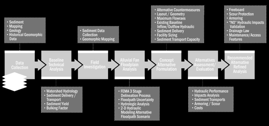
15 Basic Countermeasure Planning and Design Process


16 Baseline Technical Analysis Key Foundation for Engineering Design
17 Countermeasure Levees / Dikes / Diversions

18 Examples - Alluvial Fan Levee Characteristics

19 Examples - Alluvial Fan Levee Characteristics

20 Examples - Alluvial Fan Levee Characteristics

21 Examples - Alluvial Fan Levee Characteristics

22 Examples - Alluvial Fan Levee Characteristics


23 Example - Alluvial Fan Dike vs. Levee


24 Example - Alluvial Fan Dike vs. Levee


25 Critical Design Objectives for Levees on Alluvial Fan Minimize Potential for Overtopping Prevent failure of Embankment Slope Revetment Eliminate failure from Erosion Critical Design calculations: Levee Height Revetment Toedown Depth


26 Minimum Applicable FEMA Requirements Applicable NFIP Regulations Levees 44 CFR Ch Alluvial Fans 44 CFR Ch Minimum Riverine Levee Freeboard 3.0 feet and 4.0 feet at Bridge Structures Supercritical hydraulics Inspection and Maintenance program Settlement Interior drainage Embankment geotechnical requirements Embankment protection Upstream Termination Freeboard 3.5 feet

27 Critical Levee Design Features and Components
28 Additional Critical Levee Design Elements 1. Alignment Orientation Angle / Horizontal Alignment 2. Termination Points 3. Embankment Cross Section Geometry 4. Levee Height Levee Vertical Profile 5. Revetment or Armoring


29 Typical Levee Section Design Elements

30 Special Design Considerations for Levees on Alluvial Fans Variable Flow Paths Direct Flow Impingement from Alternate Flow Paths Sediment Ramping Debris Deposition Local Scour Channel Entrenchments High Velocity and Erosive Flows Water Surface Runup / Super-elevation on Upstream Side of Levee Impact Forces from High Velocity Flows
31 Step 1 - Levee Alignment Selection Levee Orientation Relative to Fan Geometry Optimum or Maximum Acceptable Divergence Angle Maximum Horizontal Limits of Levee Entire Fan Tie to Limits of Alluvial Fan Limited by Risk Assessment and Historical Flow Paths

32 Evaluating Effects of Alternate Flowpath Impingement Direct Impingement Would Result in Alternate flow Path Parallel to Levee Reduced Slope for Alternate Flow Path and Reduced Sediment Transport Capacity Aggradation Occurs Along Alternate Flow Path to Re-establish Sediment Equilibrium Area Between New Bed Profile and Existing Bed Profile Filled from the Differential Sediment Transport Rates
33 Evaluating Effects of Alternate Flow Path Impingement Calculate the Maximum Deposition Height at Levee: Calculate the deposition volume from the Sediment transport rates and hydrographs Deposition width from the self-forming channel width Applying geometrical relations maximum deposition depth computed at contact point Trial and Error Procedure Applied to Vary Contact Length along Levee for Maximum Depth
34 Upstream Levee Termination Points Extend to maximum limits of fan flooding Increase freeboard per FEMA Extend to hard-point for tie-in Potential for flanking if Levee cannot be extended to maximum fan flooding limits May not be economically feasible or environmental / jurisdictional limitations / property ownership Estimate the amount of flow that will flank upstream limits of levee Apply French s procedure or Flowpath Uncertainty Analysis
35 Step 2 - Alluvial of Alluvial Fan Hydraulics For Flood Protection Limited Procedures Available for Evaluation of Alluvial Fan Hydraulics Empirical Procedures to Evaluate Self-Forming Channel Hydraulics Dawdy (Critical depth stabilize where decrease in depth results in two-hundred fold increase in width) W = 9.5 Q 0.4 Edwards - Thielman (Application of Mannings Equation and Dawdy procedure) W = (Qn) 3/8 S 3/16 Fixed Bed Water Surface Profile Hydraulic Models (HEC-RAS) Cross Section Orientation 2 - dimensional Hydraulic Models (ie. FLO-2D, MIKE, HEC-RAS 2D)

36 Approximating Self-forming Channel Hydraulics of Alluvial Fan Dawdy Empirical Procedure Alluvial Fan Hydraulics Channel Width W = 9.5 Q 0.4 Procedure Assumes Critical Depth N F = 1.0 Can develop the following hydraulic relationships for self forming channel Velocity = 1.5 Q 0.2 Depth = 0.07 Q 0.4 Unit Flowrate = q = Q / W = Q 0.6 Shear Velocity = V * = (grs) 1/2

37 Alluvial Fan Water Surface Hydraulics for Flood Protection HEC-RAS Hydraulics Analysis with Levee System Mannings roughness value selection Strickler & Anderson Equations for mannings based on bed material size n = 0.04 d s 1/6 Cowan s procedure Orientation of HEC-RAS cross sections with Levee 1. Parallel to fan contours 2. Normal to Levee orientation Intent is to maximize the depth to prevent overtopping for worst case Compare analysis with empirical fan hydraulics 2-D analysis for validation only, NOT design

38 Multiple Orientations of HEC-RAS Cross Sections Normal to Contour Orientation Perpendicular Transverse Levee

39 Step 3 - Levee Revetment / Armoring Requirements Historically Unarmored Levees are Ineffective Armoring Selection Based Upon Tractive Force or Velocity Requirements Alternative Revetments Available Concrete Slope Lining Grouted Stone Soil Cement Rock Rip-Rap Evaluate Performance and Least Cost
40 Step 4 - Evaluation of Levee Height Requirements Levee Height Accounts for Moveable Bed and Rigid Boundary Conditions Calculate Height from Summation of Individual Components: Bedform Height Superelevation Flow Depth Compared to Critical Depth Deposition from Alternate Flow Path Height Levee = Depth flow + Z deposition + Y superelevation + 1/2 Antidune Height + F.B. (eqn.1) Height Levee = Critical Depth + F.B. (eqn.2) Compare Calculated Height to Total Specific Energy
41 Definition of Levee Design Variables
42 Levee Height Design Variables Antidune Height: V 2 (Kennedy) If Calculated Antidune Height Exceeds Flow Depth, Use Flow Depth and (2) Self- Calculate Hydraulics for (1) Actual Flow Depths forming Channel Superelvation: 1.3 V 2 (b+2zd) / (gr) Minimum Radius Calculated From Topwidth Equal to Curve Tangent Aggradation Potential (see Impingement Analysis) If Depth plus Superelevation Exceeds Specific Energy then Use Specific Energy
43 Step 5- Levee Toe-down Protection Requirements Primary Failure of Mechanism of Bank Protection is Scour Below Revetment Toe Depth Toe Depth Evaluated Through Empirical Design Charts / Tables Toe depth Calculated From Summation of Individual Components: Bedform Bend Scour Low flow Incisement Contraction Scour (Applied only at Channel Entrance for Training Levees)

44 Levee Toe-down Protection Requirements Hydraulics Evaluated for (1) Actual Flow Depths and (2) Selfforming Channel Hydraulics Z Toe Down = Z Bend + Z Contraction + Z Bedform + Z Low Flow Incisement Compare Calculated Maximum Bed change to Empirical Toedown Design Charts

45 Step 6 -Additional Levee Design Considerations Uncertainty of Levee Performance Levee Closures Long Term Maintenance Levee Crossings Vehicular Access for Flood-fighting Aesthetics Environmental Mitigation / Maintain Natural Flowpaths Freeboard Least cost-evaluation of Alternative Systems
46 Summary of Design Procedures for Levees on Alluvial Fans Evaluate both Rigid Boundary and Alluvial Channel Hydraulics Apply Simplified Alluvial Fan Hydraulics Development Horizontal Alignment to Minimize Impacts Levee Height Calculated to include Maximum Flow Depth and Aggradation Revetment Toe-down Depth Calculated Below Maximum Potential Scour Depth Slope Revetment Designed to Resist Maximum Tractive Force
47 Countermeasure - Channel / Conveyance Facility

48 Channelization Alternative Design Options


49 Alluvial Fan Rigid Channels Design Issues & Considerations Manning s Factor for Bed Load Sediment Deposition Bulking Factor Debris/Sediment Flow Regime CChange
 Geometry also dependent on providing similar sediment transport capacity as upstream delivery Lateral inflows to")
 initial streambed elevation, and (2) long term stabilized")
50 Channelization Hydraulic Sizing / Capacity Initial sizing/geometry flexible or earthen channel whole fan channel inflows utilize self-forming channel width (Dawdy equation) Geometry also dependent on providing similar sediment transport capacity as upstream delivery Lateral inflows to supercritical channel Side spillway entrance preferred limit surface wave disturbances Completely submerged lateral inflow pipes Analyze for high and low roughness coefficient for stability and capacity Analyze streambed at (1) initial streambed elevation, and (2) long term stabilized streambed


51 Channelization Sediment Transport Capacity Deposition / Degradation Fully armored channel should have sediment transport capacity that exceeds the upstream sediment inflow to avoid deposition Partially armored or earthen channel should have sediment transport that is in general equilibrium or stable so that the sediment transport capacity equals the sediment inflow or delivery from the upstream Calculate equilibrium slope based the hydraulics of the proposed channel, sediment characteristics, and sediment bedload inflow Adjust channel dimensions and slope until equilibrium achieved


52 Equilibrium Slope Analysis Sediment Continuity Analysis Sediment continuity analysis Calculate incoming sediment load from supply reach Worst case evaluate reduced sediment inflow for flatter slope Adjust slope of channel reach with revised hydraulics until sediment transport rate equals the supply

 Super elevation Aggradation Bedform (dune")
53 Channelization Armoring / Erosion Protection Bank Revetments Only (earthen bottom) Hydraulic shear resistance and abrasion resistance at invert Abrasion resistance Sacrificial wearing surface (additional concrete thickness) Wear cones (measures Stable channel slope Toe down elevation (similar to levee) Degradation Local scour Bedform Freeboard Top elevation revetment (similar to levee) Super elevation Aggradation Bedform (dune height)
54 Countermeasure - Grade Control Structures


55 Grade Control Design Background Two Basic Types of Grade Control Structures 1. Invert hard point to resist erosion/degradation 2. Hydraulic control generating water surface upstream Design Overview Optimizing Hydraulics & Economics Location Type of structure Locations Spacing and net drop height key design assessment Other factors

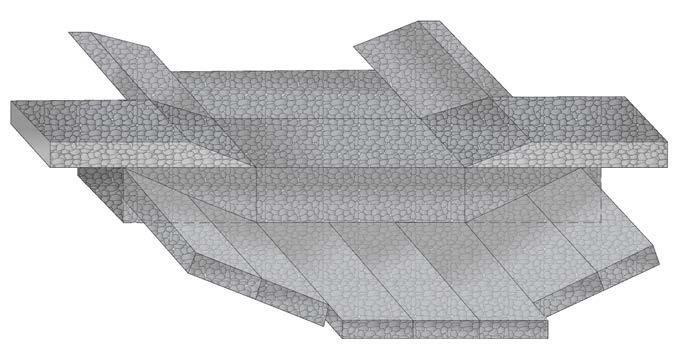
56 Grade Control Structure Alternative Design Variations


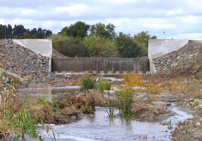
57 Grouted Rock Grade Control
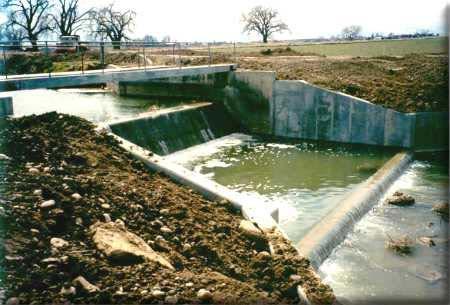
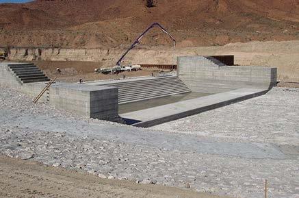
58 Reinforced Concrete Grade Control


59 Gabion Grade Control


60 Hydraulic Design of Grade Control
 and maximum allowable drop height (H max")

61 Horizontal Spacing / Siting Grade Control Structures Spacing limited by equilibrium slope (S eq ) and maximum allowable drop height (H max ) LL = SS 00 SS eeee HH H max governed by type of structure, hydraulic criteria, energy dissipation, structure stability/forces, costs, safety

62 Drop Structure Spacing - Channel Equilibrium Slope Analysis Upstream sediment supply is a controlling factor assessing channel response. Balance of incoming sediment supply and transport capacity Application of multiple procedures since most difficult to reliably define 1. Geomorphic Procedures Extrapolate historical trends 2. Sediment Transport - Empirical Equilibrium Equations Static equilibrium (incipient motion) Dynamic equilibrium 3. Sediment Balance/Continuity Analysis 4. Sediment Transport Modeling Long Term
 3/4 Meyer-Peter Muller S L = K mpm (Q/Q bf")
 0.75 Henderson S L = 0.44 D 90 1.15 Q 0.")
63 Channel Equilibrium Slope Analysis Empirical Equations Incipient Motion Shields diagram SS eeee = ττ cc γγ ww dd and Schoklitsch method S L = K s (D W bf /Q) 3/4 Meyer-Peter Muller S L = K mpm (Q/Q bf ) (n s /D 90 1/6 ) 3/2 D / d Regime / Sediment Transport Bray S L = Q D BUREC S L = ( D 50 W bf / Q) 0.75 Henderson S L = 0.44 D Q 0.46 ττ = ττ cc (γγ ss γγ ww )DD ss

64 Channel Equilibrium Slope Analysis Design Aids Guidance Design aid tools for equilibrium slope guidance Offers tentative guideline and brackets stable slope US ACOE EM Regional geomorphic based stability curves versus drainage area
 Many agencies limit to 5-feet maximum Drops without energy dissipating appurtenances")
 1 (V) (maximum slope) flatter slopes assists in")
 1 or 2 feet Difference between sequent")

65 General Suggested Guidelines / Criteria for Grade Structure Sizing Maximum Net Drop Height (H d ) Many agencies limit to 5-feet maximum Drops without energy dissipating appurtenances such as chute block/baffle blocks limit drop heights less than critical depth (y c ) low height drop Sloping Chute Slope 4(H) 1 (V) (maximum slope) flatter slopes assists in preventing reverse roller waves Stilling Basin Length 60% length of hydraulic jump Minimum End Sill Height 1/6 of sequent depth (1/6 y 2 ) 1 or 2 feet Difference between sequent depth and downstream tail-water Horizontal Siting Limitations Not within horizontal curved reaches, minimum 200-feet upstream or downstream of curve. Downstream/Upstream Flexible Armoring 10-feet
 yy ss = 11. 3333qq 00.5555 HH tt 00.")

66 Local Scour Analysis of Structure Vertical Drop Scour Veronese method (USBR) yy ss = qq HH tt TTTT Maximum scour depth occurs at distance downstream 6 x scour depth Scour hole extend a distance downstream approximately 12 time scour depth
67 Countermeasure - Detention Storage / Debris Basin


68 Debris Basin Design Features Basin Minimum Design Elements Basin storage volume Multiple storm events including 100-year and several smaller events Embankment or debris retaining structure Low-level outlet tower Upstream inlet / training facilities Downstream outlet Primary Spillway Temporary storage/drying area Storage volume access ramps / roadway


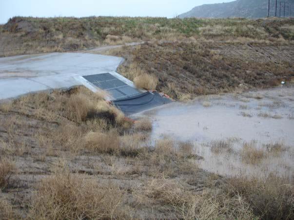
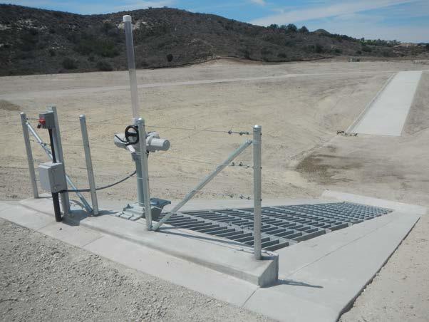
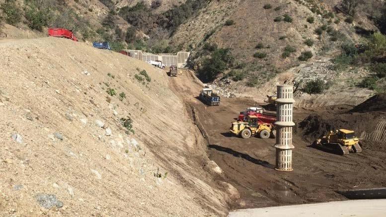
69 Low-Level Outlet Tower Configurations
 Sediment yield either supply limited or transport limited Alluvial fans generally")
")
 computed through the sediment transport capacity of upstream channel Calculate hydraulic rating curve")
")
70 Debris Basin Design Consideration Sediment Yield / Delivery Watershed sediment production vs. sediment delivery (yield) Sediment yield either supply limited or transport limited Alluvial fans generally transport limited which is why depositional feature Watershed sediment/debris production calculated standard empirical methods US Army Corps of Engineer, Los Angeles District Debris Method (regression equations) Modified Universal Soil Loss Equation (MUSLE) Fire and Resource Assessment program (FRAP) Sediment delivery (yield) computed through the sediment transport capacity of upstream channel Calculate hydraulic rating curve for upstream inflow channel Apply appropriate sediment transport bedload equation to hydraulic rating curve Apply calculate sediment transport rate to flood hydrograph discharge ordinates Calculate volume (yield) under the sediment hydrograph
71 Debris Basin Design Considerations Sediment Trap Efficiency Large reservoirs deposition (ACOE) Brune s curve (not recommended dry) Brown s curve Churchill s curve (sediment index method)
72 Debris Basin Design Considerations Sediment Trap Efficiency Small reservoir / basin Sediment theory for removal of sediment dynamic conditions (EPA, 1986) RR dd = nn VV ss = settling (fall) velocity of particles (Rubey s eqn. or Stokes Law) n = turbulence or short circuiting coefficient (n=1 poor, n=3 good, n>5 very good, and n= infinity, ideal performance) QQ = peak flowrate AA = surface area of the basin RR dd = fraction of solids removed under dynamic conditions VV ss QQ/AA nn


73 Debris Basin Design Considerations Sediment Storage / Deposition Patterns Top-set slope sediment delta ½ upstream streambed slope Fluvial sediment transport models (HEC-6 / FLUVIAL12)


74 Debris Basin Design Features Layout / Geometry Length to width ratios should always exceed 2:1 avoid short circuiting Triangular shaped basins locate inlet at narrow end of basin and expands to outlet Maximum Design Water Surface / Freeboard Water surface profile for design storm on the maximum sediment storage profile in basin. Typical criteria is 100-year sediment storage plus water surface profile for design storm such as 100-year Assumes cleanout of basin after loss of designated storage volume
75 Case Study Palm Creek Ranch (Thousand Palms, CA) Subdivision Protective Countermeasure Application


76 Thousands Palms, CA Proposed Residential Subdivision

77 Proposed Residential Subdivision Layout Interception Channel Conveyance Channel Dispersion Channel


78 Applied FEMA 3-Phase Approach Alluvial Fan Flood Hazards Geomorphic / 2D MIKE Modeling Alluvial Fan Geomorphic Assessment Flowpath Uncertainty Virtual Levees
79 2D MIKE Floodplain Modeling Four Scenarios Virtual Levees Existing Conditions No.1

80 2D MIKE Floodplain Modeling Four Scenarios Virtual Levees Existing Conditions No.2

81 2D MIKE Model Established Existing Flow In and Out Project Boundary Divide into Segments

82 HEC-RAS Modeling Used to Compute Detailed Water Surface and Lateral Outflows
83 Case Study Lowe Reserve (Palm Desert, CA) Whole Fan Structural Control Measures
84 Project Vicinity Map

85 The Reserve Development Project - Location & Description Location in both cities of Palm Desert and Indian Wells, CA High-End luxury residential golf course development 500 acres of land adjacent to Ironwood Country Club Situated entirely on the active Deep Canyon alluvial fan Proposed 18-hole championship golf course 250 residential sites Encompass portion of Living Desert regional debris basin

86 Existing Conditions Alluvial Fan - Desert Hydrology

87 Aerial View - Pre Construction 1996

88 Aerial View - Post Construction 2005 Project limits

89 Aerial Schematic of Development Area
90 Watershed Description & Hydrology 46.4 square mile deep Canyon Watershed Tributary to living desert debris basin Deep canyon is tributary to Whitewater River Two independent drainage basins tributary to project boundary (A & B) Extremely rugged mountains and steep rocky canyons of Santa Rosa mountains Elevation variation extremes from 8,716 feet to 460 feet at project 17.7 miles watershed length Average slope 9%
 Flood Control Channel 5,000 feet long Plunge-pool channel outlet structure (Net Drop 18 feet) Small entrenched sediment basin 1,400 feet golf")
91 Description of Channelization Facilities Twelve concrete grade control structures (Net Drop 6.5 feet) Flood Control Channel 5,000 feet long Plunge-pool channel outlet structure (Net Drop 18 feet) Small entrenched sediment basin 1,400 feet golf course channel Outlet water feature / plunge pool grade control
92 Proposed Reserve Development With Flood Control Improvements Transverse Levee Main Channel Existing Debris Basin Transverse Levee Outlet Structure Secondary Channel


93 Plunge Pool Channel Outlet With Aesthetic Treatment


94 Plunge Pool Channel Outlet With Aesthetic Treatment


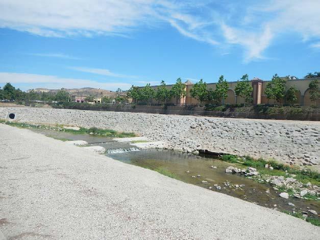
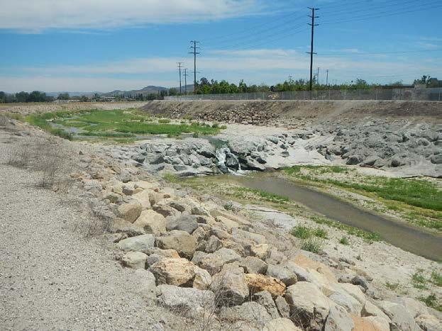
95 Flood Control Primary Channel / Grade Control

96 Levee & Grade Control Post Cosntruction Transverse Levee System Grade Control Structure

97 Channel / Grade Control Currently
98 Physical Model Study for Grade Control Structure Model Objectives Evaluate the modification to the Erosion patterns with alternative design of grade control structures Investigate the hydraulics of different grade control geometric configurations Determine the effect to the local scour from an artificial horizontal armor blanket
 Flume height 42 Sand bed material 60% medium to coarse sand, 20% pea")
99 Physical Model & Experiment Description Model construction and operated by PACE Experimental setup located outdoors under protected covered carport in Palm Desert 40-foot segment with plexiglass side Constructed ring-embankment storage reservoir 80-foot long and 24 wide flume 2-10 horsepower pumps (1,800 gpm at 16-ft head) Flume height 42 Sand bed material 60% medium to coarse sand, 20% pea gravel. 20% medium gravel

100 Hydraulic Model Scaling to Prototype Froude Law Scales selected to provide the minimum dimensions which erosion features could be adequately observed and measured Linear scale of Lr = 1:16 Discharge sable Qr = 1:1,024 Time scale Tr = 1:16 Velocity scale Vr = 1:16 Selection of model sand-bed material


101 Modeling Experiment Setup / Operation Model Setup With Drop Structure Before Water Grade Control Structure at Peak Flow / Scour Hole
102 Recommendation and Conclusions From Model Study Investigation Rip-rap armor blanket provided downstream from toe of grade control structure Length of armor blanket a minimum of 30-feet Blanket should be configured so it resembles shape of the scour hole Thickness of the armor blanket should be a minimum of 6.5-feet with 48 diameter rock Geometry of the rock blanket is important and should provide a 3-foot high thickened sill Minimum vertical height of the concrete lining for chute toedown is 16-feet compared to the original 24-feet from empirical equations. Cost Savings of $1M
103
LEVEE DESIGN FOR FLOOD PROTECTION ON ALLUVIAL FANS
 LEVEE DESIGN FOR FLOOD PROTECTION ON ALLUVIAL FANS BRUCE M. PHILLIPS 1 ABSTRACT The dynamic nature of alluvial fans in arid environments offers numerous floodplain management challenges primarily due to
INFLOW DESIGN FLOOD CONTROL SYSTEM PLAN 40 C.F.R. PART PLANT YATES ASH POND 2 (AP-2) GEORGIA POWER COMPANY
 GEORGIA POWER COMPANY") INFLOW DESIGN FLOOD CONTROL SYSTEM PLAN 40 C.F.R. PART 257.82 PLANT YATES ASH POND 2 (AP-2) GEORGIA POWER COMPANY EPA s Disposal of Coal Combustion Residuals from Electric Utilities Final Rule (40 C.F.R.
INFLOW DESIGN FLOOD CONTROL SYSTEM PLAN 40 C.F.R. PART 257.82 PLANT YATES ASH POND 2 (AP-2) GEORGIA POWER COMPANY EPA s Disposal of Coal Combustion Residuals from Electric Utilities Final Rule (40 C.F.R.
Technical Memorandum No
 Pajaro River Watershed Study in association with Technical Memorandum No. 1.2.10 Task: Evaluation of Four Watershed Conditions - Sediment To: PRWFPA Staff Working Group Prepared by: Gregory Morris and
Certification Process for North Indio East Side Dike in the Coachella Valley
 Certification Process for North Indio East Side Dike in the Coachella Valley September 7, 2016 Brady McDaniel (Northwest Hydraulic Consultants) Contributors Andrey Shvidchenko, Brent Wolfe and Jimmy Pan
Countermeasure Calculations and Design
 Countermeasure Calculations and Design Summarized from Bridge Scour and Stream Instability Countermeasures, Experience, Selection, and Design Guidance, Second Edition, Publication No. FHWA NHI 01-003,
Degradation Concerns related to Bridge Structures in Alberta
 Degradation Concerns related to Bridge Structures in Alberta Introduction There has been recent discussion regarding the identification and assessment of stream degradation in terms of how it relates to
Chapter 7 Mudflow Analysis
 Chapter 7 Mudflow Analysis 7.0 Introduction This chapter provides information on the potential and magnitude of mud floods and mudflows that may develop in Aspen due to rainfall events, snowmelt, or rain
[1] Performance of the sediment trap depends on the type of outlet structure and the settling pond surface area.
![[1] Performance of the sediment trap depends on the type of outlet structure and the settling pond surface area.](/thumbs/76/74245181.jpg "[1] Performance of the sediment trap depends on the type of outlet structure and the settling pond surface area.") Sediment Trench SEDIMENT CONTROL TECHNIQUE Type 1 System Sheet Flow Sandy Soils Type 2 System [1] Concentrated Flow Clayey Soils Type 3 System [1] Supplementary Trap Dispersive Soils [1] Performance of
Sediment Trench SEDIMENT CONTROL TECHNIQUE Type 1 System Sheet Flow Sandy Soils Type 2 System [1] Concentrated Flow Clayey Soils Type 3 System [1] Supplementary Trap Dispersive Soils [1] Performance of
Rock Sizing for Waterway & Gully Chutes
 Rock Sizing for Waterway & Gully Chutes WATERWAY MANAGEMENT PRACTICES Photo 1 Rock-lined waterway chute Photo 2 Rock-lined gully chute 1. Introduction A waterway chute is a stabilised section of channel
Stone Outlet Sediment Trap
 3.12 Sediment Control Description: A stone outlet sediment trap is a small detention area formed by placing a stone embankment with an integral stone filter outlet across a drainage swale for the purpose
Rock Sizing for Small Dam Spillways
 Rock Sizing for Small Dam Spillways STORMWATER MANAGEMENT PRACTICES Photo 1 Rock-lined spillway on a construction site sediment basin Photo 2 Rock-lined spillway on a small farm dam 1. Introduction A chute
Sediment Trap. A temporary runoff containment area, which promotes sedimentation prior to discharge of the runoff through a stabilized spillway.
 Sediment Trap SC-15 Source: Caltrans Construction Site Best Management Practices Manual, 2003. Description A temporary runoff containment area, which promotes sedimentation prior to discharge of the runoff
Summary of Hydraulic and Sediment-transport. Analysis of Residual Sediment: Alternatives for the San Clemente Dam Removal/Retrofit Project,
 Appendix N SUMMARY OF HYDRAULIC AND SEDIMENT-TRANSPORT ANALYSIS OF RESIDUAL SEDIMENT: ALTERNATIVES FOR THE SAN CLEMENTE DAM REMOVAL/RETROFIT PROJECT, CALIFORNIA the San Clemente Dam Removal/Retrofit Project,
Rock Sizing for Batter Chutes
 Rock Sizing for Batter Chutes STORMWATER MANAGEMENT PRACTICES Photo 1 Rock-lined batter chute Photo 2 Rock-lined batter chute 1. Introduction In the stormwater industry a chute is a steep drainage channel,
Appendix E Guidance for Shallow Flooding Analyses and Mapping
 Appendix E Guidance for Shallow Flooding Analyses and Mapping E.1 Introduction Different types of shallow flooding commonly occur throughout the United States. Types of flows that result in shallow flooding
Standards for Soil Erosion and Sediment Control in New Jersey May 2012
 STANDARD FOR SEDIMENT BASIN Definition A barrier, dam, excavated pit, or dugout constructed across a waterway or at other suitable locations to intercept and retain sediment. Basins created by construction
Chapter 7 Mudflow Analysis
 Chapter 7 Mudflow Analysis 7.0 Introduction This chapter provides information on the potential and magnitude of mud floods and mudflows that may develop in Aspen due to rainfall events, snowmelt, or rain
Tom Ballestero University of New Hampshire. 1 May 2013
 Tom Ballestero University of New Hampshire 1 May 2013 1 Hydrology 2 Basic Hydrology Low flows most common Flows that fill the stream to the banks and higher are much less common Filling the stream to the
5. ROADSIDE AND MEDIAN CHANNELS
 5. ROADSIDE AND MEDIAN CHANNELS Roadside and median channels are open-channel systems which collect and convey stormwater from the pavement surface, roadside, and median areas. These channels may outlet
Aquifer an underground zone or layer of sand, gravel, or porous rock that is saturated with water.
 Aggradation raising of the streambed by deposition that occurs when the energy of the water flowing through a stream reach is insufficient to transport sediment conveyed from upstream. Alluvium a general
APPENDIX B WORKSHEETS & EXHIBITS
 APPENDIX B WORKSHEETS & EXHIBITS A worksheet provides the designer a representation of a measure that allows for input of specific design criteria. The plan designer will be required to assess field conditions
Upper Mississippi River Basin Environmental Management Program Workshop
 Presentation to the Upper Mississippi River Basin Environmental Management Program Workshop by Michael Rodgers River Engineer US Army Corps of Engineers, St. Louis District August 17, 2007 Engineering
The last three sections of the main body of this report consist of:
 Threatened and Endangered Species Geological Hazards Floodplains Cultural Resources Hazardous Materials A Cost Analysis section that provides comparative conceptual-level costs follows the Environmental
CASE STUDIES. Introduction
 Introduction The City of Winston-Salem faces the challenge of maintaining public infrastructure (e.g., water and sewer lines, storm drains, roads, culverts and bridges) while minimizing the potential impacts
Technical Memorandum. To: From: Copies: Date: 10/19/2017. Subject: Project No.: Greg Laird, Courtney Moore. Kevin Pilgrim and Travis Stroth
 Technical Memorandum To: From: Greg Laird, Courtney Moore Kevin Pilgrim and Travis Stroth 5777 Central Avenue Suite 228 Boulder, CO 80301 www.otak.com Copies: [Electronic submittal] Date: 10/19/2017 Subject:
Hydraulics of bendway weirs
 River Basin Management IV 389 Hydraulics of bendway weirs C. Thornton 1, S. Abt 1, D. Baird 2 & R. Padilla 3 1 Colorado State University, Fort Collins, CO, USA 2 U.S. Bureau of Reclamation, Denver, CO,
Four Mile Run Levee Corridor Stream Restoration
 Four Mile Run Levee Corridor Stream Restoration 30% Design Summary U.S. Army Corps of Engineers, Baltimore District Presentation Outline Four Mile Run 1.) Historic Perspective 2.) Existing Conditions 3.)
Chutes Part 5: Rock linings
 Chutes Part 5: Rock linings DRAINAGE CONTROL TECHNIQUE Low Gradient Velocity Control Short-Term Steep Gradient Channel Lining Medium-Long Term Outlet Control [1] Soil Treatment Permanent [2] [1] Chutes
CONCEPTS Conservational Channel Evolution and Pollutant Transport System
 CONCEPTS Conservational Channel Evolution and Pollutant Transport System Eddy J. Langendoen Watershed Physical Processes Research Unit National Sedimentation Laboratory USDA Agricultural Research Service
APPENDIX B Hydraulic Considerations for Pipeline Crossings of Stream Channels
 APPENDIX B Hydraulic Considerations for Pipeline Crossings of Stream Channels B-1 B-2 APPENDIX B HYDRAULIC CONSIDERATIONS FOR PIPELINE CROSSINGS OF STREAM CHANNELS Pipeline crossings of perennial, intermittent,
APPENDIX G APPENDIX G SEDIMENT CONTAINMENT SYSTEM DESIGN RATIONALE
 APPENDIX G SEDIMENT CONTAINMENT SYSTEM DESIGN RATIONALE March 18, 2003 This page left blank intentionally. March 18, 2003 G-2 FIGURES Page # Figure G.1 Estimated Runoff from Precipitation Over Different
Fish Passage at Road Crossings
 Fish Passage at Road Crossings 1 Crossing Design Workshop Outline 1:00 to 2:00 Intro, Design Overview, Channel Width 2:00 to 2:15 Break 2:15 to 3:15 No-Slope, Stream Simulation Design 3:15 to 3:30 Break
SCOPE OF PRESENTATION STREAM DYNAMICS, CHANNEL RESTORATION PLANS, & SEDIMENT TRANSPORT ANALYSES IN RELATION TO RESTORATION PLANS
 DESIGN METHODS B: SEDIMENT TRANSPORT PROCESSES FOR STREAM RESTORATION DESIGN PETER KLINGEMAN OREGON STATE UNIVERSITY CIVIL ENGINEERING DEPT., CORVALLIS 2 ND ANNUAL NORTHWEST STREAM RESTORATION DESIGN SYMPOSIUM
Pirai river (Bolivia)
") Pirai river (Bolivia) Confluent of the Amazon river which average discharge is only 6 m3/s, but with peak discharge over 5000 m3/s, a challenge for river basin management and for flood control HYDROEUROPE
Pirai river (Bolivia) Confluent of the Amazon river which average discharge is only 6 m3/s, but with peak discharge over 5000 m3/s, a challenge for river basin management and for flood control HYDROEUROPE
Step 5: Channel Bed and Planform Changes
 Step 5: Channel Bed and Planform Changes When disturbed, streams go through a series of adjustments to regain equilibrium with the flow and sediment supply of their watersheds. These adjustments often
Why Geomorphology for Fish Passage
 Channel Morphology - Stream Crossing Interactions An Overview Michael Love Michael Love & Associates mlove@h2odesigns.com (707) 476-8938 Why Geomorphology for Fish Passage 1. Understand the Scale of the
Technical Review of Pak Beng Hydropower Project (1) Hydrology & Hydraulics and (2) Sediment Transport & River Morphology
 Hydrology & Hydraulics and (2) Sediment Transport & River Morphology") Technical Review of Pak Beng Hydropower Project (1) Hydrology & Hydraulics and (2) Sediment Transport & River Morphology The 2 nd Regional Stakeholder Forum The Pak Beng Hydropower Project 5 th May 2017
Technical Review of Pak Beng Hydropower Project (1) Hydrology & Hydraulics and (2) Sediment Transport & River Morphology The 2 nd Regional Stakeholder Forum The Pak Beng Hydropower Project 5 th May 2017
Materials. Use materials meeting the following.
 208.01 Section 208. SOIL EROSION AND SEDIMENTATION CONTROL 208.01 Description. Install and maintain erosion and sedimentation controls to minimize soil erosion and to control sedimentation from affecting
Technical Memorandum No Sediment Model
 Pajaro River Watershed Study in association with Technical Memorandum No. 1.2.9 Sediment Model Task: Development of Sediment Model To: PRWFPA Staff Working Group Prepared by: Gregory Morris and Elsie Parrilla
Section 4: Model Development and Application
 Section 4: Model Development and Application The hydrologic model for the Wissahickon Act 167 study was built using GIS layers of land use, hydrologic soil groups, terrain and orthophotography. Within
YELLOWSTONE RIVER FLOOD STUDY REPORT TEXT
 YELLOWSTONE RIVER FLOOD STUDY REPORT TEXT TECHNICAL REPORT Prepared for: City of Livingston 411 East Callender Livingston, MT 59047 Prepared by: Clear Creek Hydrology, Inc. 1627 West Main Street, #294
APPENDIX B DESIGN CRITERIA FOR TEMPORARY WATER QUALITY BMPS USED DURING CONSTRUCTION
 APPENDIX B DESIGN CRITERIA FOR TEMPORARY WATER QUALITY BMPS USED DURING CONSTRUCTION This Appendix presents design criteria and example calculations for the following temporary water quality BMPs for use
Rock & Aggregate Drop Inlet Protection
 Rock & Aggregate Drop Inlet Protection SEDIMENT CONTROL TECHNIQUE Type 1 System Sheet Flow Sandy Soils Type 2 System [1] Concentrated Flow Clayey Soils Type 3 System Supplementary Trap Dispersive Soils
Bank stabilization by redirective structures on the Santa Clara River, Ventura County, CA
 116 Alex Yescas Senior Water Resources Engineer Atkins North America Bank stabilization by redirective structures on the Santa Clara River, Ventura County, CA Abstract The Santa Clara River is one of the
Open Channel Flow Part 2. Ch 10 Young, notes, handouts
 Open Channel Flow Part 2 Ch 10 Young, notes, handouts Uniform Channel Flow Many situations have a good approximation d(v,y,q)/dx=0 Uniform flow Look at extended Bernoulli equation Friction slope exactly
7.3 Sediment Delivery Analysis
 7.3 Sediment Delivery Analysis In order to evaluate potential changes in sedimentation patterns that could occur due to impacts from the FCP and LPP alignments, sediment assessment models were constructed
PENNSYLVANIA DEPARTMENT OF TRANSPORTATION ENGINEERING DISTRICT 3-0
 PENNSYLVANIA DEPARTMENT OF TRANSPORTATION ENGINEERING DISTRICT 3-0 LYCOMING COUNTY S.R.15, SECTION C41 FINAL HYDROLOGIC AND HYDRAULIC REPORT STEAM VALLEY RUN STREAM RELOCATION DATE: June, 2006 REVISED:
Sediment Transport Analysis for Stream Restoration Design: The Good, the Bad, and the Ugly.
 Sediment Transport Analysis for Stream Restoration Design: The Good, the Bad, and the Ugly. Brett Jordan Phd, PE HydroGeo Designs LLC. Land and Water Services Inc. THE GOOD THE BAD THE UGLY THE GOOD THE
Project (Project No. US-CA-62-2) Maintenance Inspection and Reports (Subtask 14.1) Inspection Report No.2
 Maintenance Inspection and Reports (Subtask 14.1) Inspection Report No.2") MEMORANDUM TO: FROM: Jim Well, Ducks Unlimited Mike Harvey, PhD, PG SUBJECT: M&T/ Llano Seco Fish Screen Project (Project No. US-CA-62-2) Maintenance Inspection and Reports (Subtask 14.1) Inspection Report
MEMORANDUM TO: FROM: Jim Well, Ducks Unlimited Mike Harvey, PhD, PG SUBJECT: M&T/ Llano Seco Fish Screen Project (Project No. US-CA-62-2) Maintenance Inspection and Reports (Subtask 14.1) Inspection Report
Carmel River Bank Stabilization at Rancho San Carlos Road Project Description and Work Plan March 2018
 Carmel River Bank Stabilization at Rancho San Carlos Road Project Description and Work Plan March 2018 EXISTING CONDITION The proposed Carmel River Bank Stabilization at Rancho San Carlos Road Project
A STUDY OF LOCAL SCOUR AT BRIDGE PIERS OF EL-MINIA
 A STUDY OF LOCAL SCOUR AT BRIDGE PIERS OF EL-MINIA Dr. Gamal A. Sallam 1 and Dr. Medhat Aziz 2 ABSTRACT Bridges are critical structures that require a substantial investment to construct and serve an important
UPPER COSUMNES RIVER FLOOD MAPPING
 UPPER COSUMNES RIVER FLOOD MAPPING DRAFT BASIC DATA NARRATIVE FLOOD INSURANCE STUDY SACRAMENTO COUTY, CALIFORNIA Community No. 060262 November 2008 Prepared By: CIVIL ENGINEERING SOLUTIONS, INC. 1325 Howe
Estimating Scour. CIVE 510 October 21 st, 2008
 Estimating Scour CIVE 510 October 21 st, 2008 1 Causes of Scour 2 Site Stability 3 Mass Failure Downward movement of large and intact masses of soil and rock Occurs when weight on slope exceeds the shear
RESERVOIR DRAWDOWN RATES/RESERVOIR DRAWDOWN TEST Iron Gate, Copco (I & II), and JC Boyle Dams
, and JC Boyle Dams") TECHNICAL MEMORANDUM No. 1 TO: Michael Bowen California Coastal Conservancy Geotechnical & Earthquake Engineering Consultants CC: Eric Ginney Philip Williams & Associates PREPARED BY: Paul Grant SUBJECT:
TECHNICAL MEMORANDUM No. 1 TO: Michael Bowen California Coastal Conservancy Geotechnical & Earthquake Engineering Consultants CC: Eric Ginney Philip Williams & Associates PREPARED BY: Paul Grant SUBJECT:
Association of State Floodplain Managers, Inc.
 Association of State Floodplain Managers, Inc. 2809 Fish Hatchery Road, Suite 204, Madison, WI 53713 Phone: 608-274-0123 Fax: 608-274-0696 Email: asfpm@floods.org Website: www.floods.org Need for Updating
STABILIZATION OF THE H&CT RAILWAY STONE DAM WALTER E. SKIPWITH, PE, JOYCE CRUM, AIA AND JOHN BAUMGARTNER, PE. Introduction.
 STABILIZATION OF THE H&CT RAILWAY STONE DAM WALTER E. SKIPWITH, PE, JOYCE CRUM, AIA AND JOHN BAUMGARTNER, PE I. A. Introduction General The Old Stone Dam is located in the upper reach of Cottonwood Creek
B-1. Attachment B-1. Evaluation of AdH Model Simplifications in Conowingo Reservoir Sediment Transport Modeling
 Attachment B-1 Evaluation of AdH Model Simplifications in Conowingo Reservoir Sediment Transport Modeling 1 October 2012 Lower Susquehanna River Watershed Assessment Evaluation of AdH Model Simplifications
Dolores River Watershed Study
 CHAPTER 4: RIVER AND FLOODPLAIN ISSUES The Dolores River falls into a category of streams in Colorado that share some unique characteristics. Like some other mountain streams in the state, it has a steep
Appendix K.2: Sediment Management Excerpt from South Orange County Hydromodification Management Plan
 Appendix K.2: Sediment Management Excerpt from South Orange County Hydromodification Management Plan 4 Sediment Supply Management Requirements Permit Order R9-2013-0001 as amended by Order No. R9-2015-0001Section
GEOMORPHIC CHANGES IN LOWER CACHE CREEK 2012
 GEOMORPHIC CHANGES IN LOWER CACHE CREEK 2012 Eric W. Larsen Technical Memorandum Prepared for Cache Creek Technical Advisory Committee Natural Resources Program Yolo County Board of Supervisors 2012 Prepared
JACINTO. Sediment Transport and Scour Analysis San Jacinto River, Stage 4 North and South Levees SAN ENGINEERING STUDY. Prepared for: Prepared by:
 ENGINEERING STUDY Sediment Transport and Scour Analysis San Jacinto River, Stage 4 North and South Levees Prepared for: Prepared by: RIVERSIDE COUNTY FLOOD CONTROL & WATER CONSERVATION DISTRICT & SAN JACINTO
Probabilistic Evaluation of a Meandering Low-Flow Channel. February 24 th, UMSRS
 Probabilistic Evaluation of a Meandering Low-Flow Channel February 24 th, 2014 2014 UMSRS 1 2 acknowledgments Low- Flow Channel (LFC) overview Proposed Diversion Channel collects runoff from: The Rush
EXAMPLES (SEDIMENT TRANSPORT) AUTUMN 2018
 AUTUMN 2018") EXAMPLES (SEDIMENT TRANSPORT) AUTUMN 2018 Q1. Using Cheng s formula estimate the settling velocity of a sand particle of diameter 1 mm in: (a) air; (b) water. Q2. Find the critical Shields parameter diameter
EXAMPLES (SEDIMENT TRANSPORT) AUTUMN 2018 Q1. Using Cheng s formula estimate the settling velocity of a sand particle of diameter 1 mm in: (a) air; (b) water. Q2. Find the critical Shields parameter diameter
Stream Simulation: A Simple Example
 Stream Simulation: A Simple Example North Thompson Creek, CO Paul T. Anderson U.S.D.A. Forest Service Here s How We Started May 2011 2-1 USDA-Forest Service Here s How We Finished Forest Service Aquatic
Low Gradient Velocity Control Short Term Steep Gradient Channel Lining Medium-Long Term Outlet Control Soil Treatment Permanent [1]
![Low Gradient Velocity Control Short Term Steep Gradient Channel Lining Medium-Long Term Outlet Control Soil Treatment Permanent [1]](/thumbs/87/96478185.jpg "Low Gradient Velocity Control Short Term Steep Gradient Channel Lining Medium-Long Term Outlet Control Soil Treatment Permanent [1]") Rock Linings DRAINAGE CONTROL TECHNIQUE Low Gradient Velocity Control Short Term Steep Gradient Channel Lining Medium-Long Term Outlet Control Soil Treatment Permanent [1] [1] The design of permanent installations
Rock Linings DRAINAGE CONTROL TECHNIQUE Low Gradient Velocity Control Short Term Steep Gradient Channel Lining Medium-Long Term Outlet Control Soil Treatment Permanent [1] [1] The design of permanent installations
Case Study 2: Twenty-mile Creek Rock Fords
 Case Study : Twenty-mile Creek Rock Fords Location Crossing Description Washington. Okanagan National Forest. Methow Valley Ranger District. Chewuch river basin, East Chewuch Road. The Twenty-mile Creek
Stage Discharge Tabulation for Only Orifice Flow
 Stage Discharge Tabulation for Only Orifice Flow DEPTH STAGE DISCHARGE (meters) (feet) (meters) (feet) (m 3 /s) (ft 3 /s) 0 0.20 0.40 0.60 0.80 1.00 1.20 1.40 1.60 1.80 2.00 0.7 1.3 2.0 2.6 3.3 3.9 4.6
Chapter 3.8: Energy Dissipators. By Dr. Nuray Denli Tokyay
 Chapter 3.8: Energy Dissipators By Dr. Nuray Denli Tokyay 3.1 Introduction A stilling basin is a short length of paved channel placed at the foot of a spillway or any other source of supercritical flow
Stream Geomorphology. Leslie A. Morrissey UVM July 25, 2012
 Stream Geomorphology Leslie A. Morrissey UVM July 25, 2012 What Functions do Healthy Streams Provide? Flood mitigation Water supply Water quality Sediment storage and transport Habitat Recreation Transportation
MATHEMATICAL MODELING OF FLUVIAL SEDIMENT DELIVERY, NEKA RIVER, IRAN. S.E. Kermani H. Golmaee M.Z. Ahmadi
 JOURNAL OF ENVIRONMENTAL HYDROLOGY The Electronic Journal of the International Association for Environmental Hydrology On the World Wide Web at http://www.hydroweb.com VOLUME 16 2008 MATHEMATICAL MODELING
THE NEED FOR AN ADDITIONAL SPILLWAY AT THE SANFORD DAM BOILING SPRING LAKES, NC. Presentation for The Brunswick County Commissioners April 20, 2015
 THE NEED FOR AN ADDITIONAL SPILLWAY AT THE SANFORD DAM BOILING SPRING LAKES, NC Presentation for The Brunswick County Commissioners April 20, 2015 The Sanford Dam Earth Dam constructed in 1961 Drainage
Modeling Great Britain s Flood Defenses. Flood Defense in Great Britain. By Dr. Yizhong Qu
 Modeling Great Britain s Flood Defenses AIRCurrents Editor s note: AIR launched its Inland Flood Model for Great Britain in December 2008. The hazard module captures the physical processes of rainfall-runoff
Annual transport rates at two locations on the fore-slope.
 Sediment Transport by Currents Fore-slope Sediment transport rates and sediment concentrations were computed from the hydrodynamic model runs as well as from direct measurements of current velocities at
PART 2:! FLUVIAL HYDRAULICS" HYDROEUROPE
 PART 2:! FLUVIAL HYDRAULICS" HYDROEUROPE 2009 1 HYDROEUROPE 2009 2 About shear stress!! Extremely complex concept, can not be measured directly!! Computation is based on very primitive hypotheses that
1 INTRODUCTION AND MAJOR FINDINGS... 1
 Memorandum To: Lindsey Clark, Stillwater Valley Watershed Council Coordinator From: Chad Raisland, Pioneer Technical Services, Inc. and Karin Boyd, Applied Geomorphology, Inc. CC: Tanya Lester, Stillwater
STREAM RESTORATION AWRA Summer Specialty Conference, GIS and Water Resources IX
 STREAM RESTORATION 2016 AWRA Summer Specialty Conference, GIS and Water Resources IX Innovative Use of 2D Hydraulic Modeling in Stream Restoration Design Presented by: Li Gao, PE and Robert Scrafford,
The effectiveness of check dams in controlling upstream channel stability in northeastern Taiwan
 Erosion, Debris Mows and Environment in Mountain Regions (Proceedings of the Chengdu Symposium, July 1992). IAHS Publ. no. 209, 1992. 423 The effectiveness of check dams in controlling upstream channel
Coarse Sediment Traps
 Coarse Sediment Traps SEDIMENT CONTROL TECHNIQUE Type 1 System Sheet Flow Sandy Soils Type 2 System [1] Concentrated Flow Clayey Soils [2] Type 3 System Supplementary Trap Dispersive Soils [1] Though primarily
CCR Rule Annual Inspection Report (cont.) 2
 2") The inspection findings consisted of maintenance items and items that were not observed to be signs or potential signs of significant structural weakness. No deficiencies or disrupting conditions that
The inspection findings consisted of maintenance items and items that were not observed to be signs or potential signs of significant structural weakness. No deficiencies or disrupting conditions that
APPENDIX D HYDROLOGY AND HYDRAULICS. Micromodel Study Hydrology and Hydraulics Analysis
 APPENDIX D HYDROLOGY AND HYDRAULICS Micromodel Study Hydrology and Hydraulics Analysis Cache River 1135 Meander Restoration MicroModel Study Revision 2a 1/4/2011 1. Introduction The US Army Corps of Engineers,
Dam Removal Analysis Guidelines for Sediment
 A review of: Dam Removal Analysis Guidelines for Sediment Joe Rathbun (Retired) rathbunj@sbcglobal.net Some Potential Sediment Issues Reservoir restoration Downstream water quality Downstream deposition
Remaining Capacity in Great Lakes Reservoirs
 US Army Corps of Engineers Detroit District Remaining Capacity in Great Lakes Reservoirs Storage Capacity Behind Great Lakes Dams Field Data and Modeling Motivation for project Project overview Data and
Subject Name: SOIL AND WATER CONSERVATION ENGINEERING 3(2+1) COURSE OUTLINE
 COURSE OUTLINE") Subject Name: SOIL AND WATER CONSERVATION ENGINEERING 3(2+1) COURSE OUTLINE (Name of Course Developer: Prof. Ashok Mishra, AgFE Department, IIT Kharagpur, Kharagpur 721 302) Module 1: Introduction and
Subject Name: SOIL AND WATER CONSERVATION ENGINEERING 3(2+1) COURSE OUTLINE (Name of Course Developer: Prof. Ashok Mishra, AgFE Department, IIT Kharagpur, Kharagpur 721 302) Module 1: Introduction and
Evaluation of Public Safety at Run-of-River Dams
 Evaluation of Public Safety at Run-of-River Dams - An Illinois Statewide Program By G. Nicholas Textor, PE, CFM Daniel W. Tornil Lee Von Gynz-Guethle, CFM Authority Section 23a of the Rivers, Lakes and
CR AAO Bridge. Dead River Flood & Natural Channel Design. Mitch Koetje Water Resources Division UP District
 CR AAO Bridge Dead River Flood & Natural Channel Design Mitch Koetje Water Resources Division UP District Old County Road AAO Bridge Map courtesy of Marquette County Silver Lake Basin McClure Basin
Appendix F Channel Grade Control Structures
 Stream Simulation Appendix F Channel Grade Control Structures This appendix briefly describes permanent grade control structures that are sometimes needed in the upstream and/or downstream reaches adjacent
3.12 Geology and Topography Affected Environment
 3 Affected Environment and Environmental Consequences 3.12 Geology and Topography 3.12.1 Affected Environment 3.12.1.1 Earthquakes Sterling Highway MP 45 60 Project Draft SEIS The Kenai Peninsula is predisposed
FOR PROJECTS INITIATED AFTER NOVEMBER 1, 2008 ITEM 716 EMBANKMENT EARTH OUTLET SEDIMENT TRAP
 AFTER NOVEMBER 1, 2008 ITEM 716 EMBANKMENT EARTH OUTLET SEDIMENT TRAP 716.1 Description. This work shall consist of furnishing, installing, maintaining, and removing temporary erosion protection and sediment
HISTORY OF CONSTRUCTION FOR EXISTING CCR SURFACE IMPOUNDMENT PLANT GASTON ASH POND 40 CFR (c)(1)(i) (xii)
(1)(i) (xii)") HISTORY OF CONSTRUCTION FOR EXISTING CCR SURFACE IMPOUNDMENT PLANT GASTON ASH POND 40 CFR 257.73(c)(1)(i) (xii) (i) Site Name and Ownership Information: Site Name: E.C. Gaston Steam Plant Site Location:
HISTORY OF CONSTRUCTION FOR EXISTING CCR SURFACE IMPOUNDMENT PLANT GASTON ASH POND 40 CFR 257.73(c)(1)(i) (xii) (i) Site Name and Ownership Information: Site Name: E.C. Gaston Steam Plant Site Location:
TSEGI WASH 50% DESIGN REPORT
 TSEGI WASH 50% DESIGN REPORT 2/28/2014 Daniel Larson, Leticia Delgado, Jessica Carnes I Table of Contents Acknowledgements... IV 1.0 Project Description... 1 1.1 Purpose... 1 Figure 1. Erosion of a Headcut...
STRUCTURAL STABILITY ASSESSMENT
 STRUCTURAL STABILITY ASSESSMENT CFR 257.73(d) Bottom Ash Pond Complex Cardinal Plant Brilliant, Ohio October, 2016 Prepared for: Cardinal Operating Company Cardinal Plant Brilliant, Ohio Prepared by: Geotechnical
Hydraulic Design of Energy Dissipators for Culverts and Channels HEC 14 September 1983 Metric Version
 Hydraulic Design of Energy Dissipators for Culverts and Channels HEC 14 September 1983 Metric Version Welcome to HEC 14 - Hydraulic Design of Energy Dissipators for Culverts and Channels Table of Contents
U-Shaped Sediment Traps
 U-Shaped Sediment Traps SEDIMENT CONTROL TECHNIQUE Type 1 System Sheet Flow Sandy Soils Type 2 System Concentrated Flow Clayey Soils [1] Type 3 System Supplementary Trap Dispersive Soils [1] Generally
Highland Lake Bathymetric Survey
 Highland Lake Bathymetric Survey Final Report, Prepared For: The Town of Highland Lake 612 Lakeshore Drive Oneonta, AL 35121 Prepared By: Tetra Tech 2110 Powers Ferry Road SE Suite 202 Atlanta, GA 30339
Riparian Assessment. Steps in the right direction... Drainage Basin/Watershed: Start by Thinking Big. Riparian Assessment vs.
 Riparian Assessment vs. Monitoring Riparian Assessment What is a healthy stream? Determine stream/riparian health Determine change or trend, especially in response to mgmt Classification = designation
Numerical modeling of sediment flushing from Lewis and Clark Lake
 University of Nebraska - Lincoln DigitalCommons@University of Nebraska - Lincoln US Army Research U.S. Department of Defense 2013 Numerical modeling of sediment flushing from Lewis and Clark Lake Jungkyu
Emergency Action Plan (EAP) Tata Pond Dam
 Tata Pond Dam") For Official Use Only Not for Public Distribution 02/03/16 Emergency Action Plan (EAP) Tata Pond Dam State of Connecticut Dam ID: 0000 Town or City, County, Connecticut Name of Dam Owner Dam Hazard Classification
For Official Use Only Not for Public Distribution 02/03/16 Emergency Action Plan (EAP) Tata Pond Dam State of Connecticut Dam ID: 0000 Town or City, County, Connecticut Name of Dam Owner Dam Hazard Classification
Borrego Springs Alluvial Fan Active and Inactive Area Mapping, County of San Diego, California. Julianne J. Miller Steve N. Bacon Richard H.
 Borrego Springs Alluvial Fan Active and Inactive Area Mapping, County of San Diego, California Julianne J. Miller Steve N. Bacon Richard H. French Outline Where is Borrego Springs, California? History
A-JACKS CONCRETE ARMOR UNITS Channel Lining and Pier Scour Design Manual
 A-JACKS CONCRETE ARMOR UNITS Channel Lining and Pier Scour Design Manual Prepared for Armortec, Inc. Bowling Green, Kentucky P.O. Box 270460 Fort Collins, Colorado 80527 (970) 223-5556, FAX (970) 223-5578
SAN JACINTO RIVER / BAUTISTA CREEK LEVEE SYSTEM RIVERSIDE COUNTY, CALIFORNIA NLD ID #
 SAN JACINTO RIVER / BAUTISTA CREEK LEVEE SYSTEM RIVERSIDE COUNTY, CALIFORNIA NLD ID # 3805010019 PERIODIC INSPECTION REPORT NO 1 GENERALIZED EXECUTIVE SUMMARY FEBRUARY 2013 FINAL RATING: MINIMALLY ACCEPTABLE