Formation Design Systems' Maxsurf Stability Tank Table Generator: Verification and Validation Study
|
|
|
- Meredith Melton
- 6 years ago
- Views:
Transcription

1 Formation Design Systems' Maxsurf Stability Tank Table Generator: Verification and Validation Study Edward Dawson Maritime Division Defence Science and Technology Organisation DSTO-TR-2968 ABSTRACT A verification and validation analysis was undertaken to prove that the Maxsurf Stability software can be used to generate platform tank calibration data in a format and standard that meets, or exceeds, the requirements imposed by the Maritime Institute of the Netherlands (MARIN) and the Cooperative Research Navies (CRNAV) ship stability working group. The results of the analyses show that the Maxsurf Stability software program (Version ) generates tank calibration data and a tank table output file that meets the aforementioned requirements. RELEASE LIMITATION Approved for public release
2 Published by Maritime Division DSTO Defence Science and Technology Organisation 506 Lorimer St Fishermans Bend, Victoria 3207 Australia Telephone: 1300 DEFENCE ( ) Fax: (03) Commonwealth of Australia 2014 AR May 2014 APPROVED FOR PUBLIC RELEASE
3 Formation Design Systems' Maxsurf Stability Tank Table Generator: Verification and Validation Study Executive Summary The FREDYN semi-non-linear time domain ship motion and manoeuvring simulation program is currently used by the Defence Science and Technology Organisation (DSTO) to conduct platform motion predictions, analyses and evaluations. An important aspect of FREDYN s functionality is its ability to simulate the effects of internal flooding on the motion response of a ship, submarine or floating structure. This development has been achieved through the combined efforts of the Cooperative Research Navies (CRNAV) working group. The FREDYN flooding module requires a database of the platform s internal compartment and tank volumes to enable it to compute the instantaneous internal flooding water level, centre of mass, free-surface effect and other fluid volume specific parameters. This database is typically generated from a three-dimensional computer aided design (CAD) model of the platform and its internal volumes and is stored as an ASCII text data file. The file is referred to as a tank table or tank calibration file. To date, the database file is generated using third party software, in particular the Paramarine integrated naval architecture design and analysis program. There is currently no restriction on which program or method is used to generate tank table database files, although the file format and content must meet the requirements specified by the Maritime Research Institute of the Netherlands (MARIN), the developers of FREDYN. Despite this relatively relaxed constraint, the CRNAV working group dictates that all flooding analyses conducted using FREDYN must be completed using a tank table file generated by an endorsed software program. Furthermore, in order to be accepted as an endorsed software program, the program must be shown to perform equally as well as or better than Paramarine at generating a tank table file and meet the data interface requirements prescribed by MARIN. In 2010 the DSTO Maritime Platforms Division (now the Maritime Division) contracted Formation Design Systems Pty. Ltd. (FDS) to incorporate a tank table file generation capability within its ship stability and hydrostatics software program then known as Hydromax (now issued as Maxsurf Stability).
4 A study was conducted to determine if Maxsurf Stability is able, at a minimum, to meet the data content, format and quality requirements that will enable it to be endorsed by the CRNAV working group and used to support analyses conducted by DSTO. The scope of the verification and validation analysis was limited to the tank calibration output file (*.OUT) generated by Maxsurf Stability. A simple box shaped barge with four internal tanks was used as the test case in accordance with the requirement specified by MARIN. Tank data were computed for the test case for a series of bodyfixed rotations (heel and trim) in addition to the upright condition. The analysis was an objective evaluation of the tank calibration file s data content, format and quality against the data interface requirements specified by MARIN and a comparative tank table file generated by MARIN using Paramarine V7.1. The results of the verification analysis indicates that the data content and format of the tank calibration file generated using Maxsurf Stability V meets all of the requirements specified by MARIN in their two interface requirements documents. The validation of the tank calibration data quality was completed by making a direct comparison against the data generated using Paramarine V7.1. The comparison indicated that there are several instances where the two data do not compare well and there is a significant relative error. An independent data set was generated using the three dimensional CAD modelling program Rhinoceros 3D V4.0 to provide an objective comparison between it and the Paramarine and Maxsurf Stability data. A comparison between the Maxsurf Stability and Rhinoceros 3D data sets indicated that the data returned by Maxsurf Stability was predominantly (69%) accurate (with no relative error). There were limited instances (29%) where the data was found to be in error by less than one percent and only a few instances (2%) where the data was in error by more than one percent but less than five percent. These errors are attributed to both numerical rounding and the numerical discretization and integration method used by Maxsurf Stability. Based on the analyses conducted and the results of the verification and validation study, it is recommended that Maxsurf Stability V be considered for acceptance and endorsed by MARIN and the CRNAV as a method for generating tank table database files.
5 Author Edward Dawson Maritime Division Edward Dawson is a Research Scientist with the Australian Defence Science and Technology Organisation. After graduating from the University of Tasmania with a Bachelor of Engineering (Naval Architecture) Edward worked in the Australian commercial and defence maritime industry as a consulting engineer. In his current role, Edward is principally involved in the surface platform hydrodynamics research and technology domain
6 This page is intentionally blank
7 DSTO-TR-2968 Contents 1. INTRODUCTION Background Scope of the Verification and Validation Acceptance Criteria VERIFICATION AND VALIDATION METHOD Test Case Model Verification of Data Format Validation of Maxsurf Stability Generated Tank Calibration Data VALIDATION ANALYSIS Coordinate System Barge and Tank Model Tank Particulars Heel and Trim Validation Analysis Matrix Tank Capacity Tank Fluid Volume Properties Quantitative Analysis: Relative Error ANALYSIS OUTCOMES AND DISCUSSION Verification Analysis Validation Analyses RECOMMENDATIONS AND CONCLUDING REMARKS APPENDIX A: TANK TABLE OUTPUT FILE VERIFICATION MATRIX APPENDIX B: MAXSURF STABILITY TANK CALIBRATION OUTPUT FILE COMPARISON WITH PARAMARINE V7.1 DATA B.1. Comparison of Maxsurf Stability against Paramarine V7.1: Volume, Sounding, LCG, VCG and TCG B.2. Comparison of Maxsurf Stability against Paramarine V7.1: Free-Surface Moment and Free-Surface Area B.3. Comparison of Maxsurf Stability against Paramarine V7.1: Volume moments of inertia (Ixx, I yy and I zz) and Product moments of inertia (I xy, I yz and I xz) APPENDIX C: MAXSURF STABILITY TANK CALIBRATION OUTPUT FILE COMPARISON WITH RHINOCEROS 3D V4.0 DATA C.1. Comparison of Rhinoceros 3D V4.0 against Maxsurf Stability: Volume, Sounding, LCG, VCG and TCG... 21
8 DSTO-TR-2968 C.2. Comparison of Rhinoceros 3D V4.0 against Maxsurf Stability: Free-Surface Moment and Free-Surface Area C.3. Comparison of Rhinoceros 3D V4.0 against Maxsurf Stability: Volume moments of inertia (I xx, I yy and I zz) and Product moments of inertia (I xy, I yz and I xz) APPENDIX D: APPENDIX E: APPENDIX F: VERIFICATION REFERENCE MAXSURF STABILITY TANK CALIBRATION FILE D.1. Maxsurf Stability Tank Calibration output file (*.OUT): MARIN barge test case in an upright (zero heel and trim) condition TANK TABLE PROCESSOR PLOT OF MAXSURF STABILITY GENERATED FREE-SURFACE AREA DATA MAXSURF STABILITY CALCULATION METHOD: SECOND MOMENTS OF INERTIA... 30
9 DSTO-TR-2968 Acronyms and Abbreviations ASCII BL CI COMP CRNAV DSTO FDS FP FS GRC LCG MARIN PERM PS RE S SB SHCP STBD SYM TCG V&V VCG American Standard Code for Information Interchange Baseline Configuration Item Compartment Cooperative Research Navies Defence Science and Technology Organisation Formation Design Systems Pty. Ltd. Forward Perpendicular Free-Surface Moment Graphics Research Corporation Longitudinal Centre of Gravity Maritime Research Institute of the Netherlands Permeability Port Side Relative Error Free-Surface Area Starboard Side Ship Hull Characteristics Program Starboard Symmetry Transverse Centre of Gravity Verification and Validation Vertical Centre of Gravity
10 DSTO-TR-2968 This page is intentionally blank
11 DSTO-TR Introduction This report presents the methodology and results of the configuration item verification and validation (V&V) analysis of the Maxsurf Stability Advanced Version (Maxsurf Stability) [1] tank calibration file generator. The independent V&V analysis was conducted within the Defence Science and Technology Organisation s (DSTO) Maritime Division. The purpose of the V&V analysis was to provide objective evidence that the Maxsurf Stability software can generate a tank calibration output file that meets the buildto requirements and the prescribed interface requirements that will enable its use with the existing semi-non-linear time domain ship motion simulation code, FREDYN [2]. 1.1 Background In recent years the Cooperative Research Navies (CRNAV) membership group has worked to develop a flooding module within FREDYN to investigate the effects of hull damage and subsequent flooding on a platform s motion response, stability and survivability. To enable these analyses, a database of the tank fluid volume properties is used in calculating the flow of water and air within the platform s compartments. The database is referred to by the Maritime Research Institute of the Netherlands (MARIN) as a Tank Table and in the context of Maxsurf Stability as a Tank Calibration file. In 2010 DSTO contracted Formation Design Systems Pty. Ltd. (FDS), the developers of the Maxsurf suite of naval architectural modelling and analysis software, to develop a tank table database generator within their existing hydrostatics and stability analysis program (then known as Hydromax but recently renamed Maxsurf Stability). The functionality implemented by the developers allows the user to use the legacy tank and compartment modelling tools and tank calibration analysis routine to generate a set of tank data for a range of heel, trim and tank fill capacity conditions. This data is then able to be exported from Maxsurf Stability as a tank calibration file (tank table) for further processing using the MARIN Tank Table Processor. Once processed the output data is appropriate for use by the FREDYN flooding module. 1.2 Scope of the Verification and Validation The scope of the V&V analysis was limited to the Maxsurf Stability generated tank calibration file (*.OUT file) containing tank calibration and compartment definition data. In the context of the analysis a *.OUT file is considered to be a discrete configuration item (CI). The V&V process did not consider the configuration or performance of the Maxsurf Stability software or its associated input data or the additional two FREDYN related files generated by the Maxsurf Stability software. The boundary of this V&V analysis is presented in Figure 1. 1
12 DSTO-TR-2968 V&V Boundary Tank Calibration File: (*.OUT) User Input Data: Hull & Tank Geometry, Heel & Trim initial condition Maxsurf Stability Advanced Software Compartment Def File: (*.XML) Hull Mesh File: (*.MSH) Figure 1 Configuration Item Verification and Validation boundary 1.3 Acceptance Criteria The explicit acceptance criteria used in the V&V analysis was sourced from the following documents published by MARIN: Tank-Table Generation: Variable Definitions & Rotation Sequence Check [3] FREDYN-PARAMARINE Interface Requirements [4]. The requirement imposed by MARIN, as the developer of FREDYN, for accepting a method to generate tank table data files (including Maxsurf Stability) is that its performance is shown to be equal to or in excess of that currently provided by the GRC Paramarine software. In addition, the Maxsurf Stability data were compared against data generated using Rhinoceros 3D [5], a third-party computer aided design (CAD) modelling program. The results of the further comparison are provided as a means of co-validating the Maxsurf Stability data against an independent and objective data set. It is proposed that the acceptance criteria for the Maxsurf Stability generated tank calibration file, and hence the implicit methods used by Maxsurf Stability, be assessed on these two comparisons and based on the endorsed build-to requirements and objective data quality metrics. The abovementioned data artefacts were used to: verify the format of the data output by Maxsurf Stability in the tank calibration output file validate the correctness of the data output by Maxsurf Stability in the tank calibration output file. 2
13 DSTO-TR Test Case Model 2. Verification and Validation Method Tank calibration files were generated for the MARIN barge benchmark model for the purpose of the V&V analysis. The MARIN box-shaped barge and its four internal tanks published by Ypma [3] were modelled using the Maxsurf Modeller Advanced version [6] naval architecture and surface modelling software program (Figure 2). A series of tank calibration files were generated using Maxsurf Stability. The MARIN barge and tank configuration is comprised of a simple box shaped hull geometry with four internal, identically sized, cube shaped tanks. This geometry has been modelled using Paramarine by researchers and software developers at MARIN to yield, among other data, tank calibration files. Consequently, existing tank calibration data and output files are available for comparison and reference purposes. 2.2 Verification of Data Format The content and format of the Maxsurf Stability generated tank calibration file was verified against the requirements stated in the MARIN FREDYN-PARAMARINE Interface Requirements document [4]. The tank calibration file data was verified against the requirements set on a complies/does not comply basis. The common verification approach used was to inspect the tank calibration file and the Maxsurf Stability User Manual [7] and compare the observed data against the requirement set. The requirements verification matrix and results are presented in Appendix A. 2.3 Validation of Maxsurf Stability Generated Tank Calibration Data The validation analysis of the Maxsurf Stability tank calibration file was completed by quantitatively comparing the numerical values computed and output in the calibration file (*.OUT) against the corresponding values determined using Paramarine (provided by Ypma [8]) and the solid modelling and volume properties calculator within the Rhinoceros 3D computer aided design software program (the objective reference data set). The analysis considered the starboard forward (SB Fwd) tank only. This was done to maintain consistency with the analysis approach and data presented by Ypma [3]. The MARIN barge SB Fwd tank was modelled in Rhinoceros 3D as a solid polyhedral for a range of tank filling levels and a range of heel and trim angles. The filling levels and heel and trim angles analysed correspond to those used by Ypma [3] and are presented in Section 3 of this report. The relative error between the Paramarine and Maxsurf Stability data and the Rhinceros 3D and Maxsurf Stability data were calculated for each parameter and test condition. The results of the validation study are presented in Appendix B and Appendix C for the Paramarine and Rhinoceros 3D comparisons respectively. 3
14 DSTO-TR Coordinate System 3. Validation Analysis The coordinate system used in the modelling, data calculation and reporting corresponds to the Ship Hull Characteristics Program (SHCP) output system presented on page 28 of Ypma [3]. The coordinate system requirement imposed on the tank calibration file (CI) is as follows: the coordinate system origin is located amidships, on the centreline and on the baseline (keel). The x axis is orientated parallel to the length of the barge and is positive forward; the y axis is orientated in the transverse direction and is positive to starboard; the z axis is orientated in the vertical direction and is positive upwards. This system results in a positive heel angle to starboard and a positive trim angle for a trim by the stern. The coordinate system is shown in Figure 2. It is important to note that the barge s body-fixed coordinate system differs from the tank body fixed system described above. As presented by Ypma [3], the barge body-fixed coordinate system has the origin at the aft perpendicular, centreline and baseline. The directions of the principal axes are: x axis is positive forwards, the y axis is positive to port and the z axis is positive upwards. 3.2 Barge and Tank Model The geometry of the barge and tanks is identical to that described by Ypma [3]. The rectangular barge is fitted with four identical tanks. Pairs of tanks are located at each end of the barge. The forward starboard (SB Fwd) tank, used as the subject of the validation analysis, is shown in Figure 2. The principal dimensions of the barge are presented in Table 1. Table 1 MARIN Barge principal dimensions Particular Length Overall Beam Depth Draft Measurement m m 7.00 m 2.00 m The majority of the SB Fwd tank s fluid volume properties are measured relative to the body-fixed datum (origin of the coordinate system) in accordance with the coordinate system presented in Section 3.1 and the reference conventions presented by Ypma [3]. The tanks moments of inertia are calculated at the centre of volume of each tank using a coordinate system that is aligned with the tanks body-fixed system. 4

15 DSTO-TR-2968 z x SB Fwd y Figure 2 MARIN Barge model with four independent tanks. The body-fixed coordinate system shown corresponds to the tanks (SHCP tank data output system). 3.3 Tank Particulars The geometric particulars of the four tanks are listed below in Table 2. Table 2 Tank geometric particulars Particular Measurement Length 5.00 m Breadth 5.00 m Height 5.00 m Capacity 125 m 3 The location of the geometric centre of the SB Fwd tank with zero fluid content and in the upright condition (no heel or trim) is presented in Table 3. Table 3 SB Fwd tank geometric centre Coordinate x y z Distance from Body-Fixed Datum m 2.50 m 2.50 m 5
16 DSTO-TR Heel and Trim Validation Analysis Matrix A matrix of five heel and trim conditions corresponding to those presented by Ypma [3] was used to conduct the validation analysis of the tank fluid volume properties. The matrix is presented in Table 4. Table 4 Heel and trim angle matrix used to conduct the validation analysis Condition Heel [deg] Trim [deg] No heel or trim Heel to port only Heel to starboard only Trim by the Head only Trim by the Stern only Tank Capacity A data set of tank volume properties were calculated for the five heel and trim angle combinations at five discrete tank capacities. The tank capacities analysed are a sub-set of the required capacities calculated by a tank table generator as stated in Ypma [4]. The tank capacities analysed are listed in Table 5. The density of the fluid in the tanks is 1 tonne per cubic metre. Table 5 SB Fwd Tank partially filled conditions Condition Percentage Full [%] Volume [m 3 ] Tank Fluid Volume Properties The following tank fluid volume properties were calculated and compared for each of the analysis conditions: 1. Sounding 2. Volume 3. Longitudinal Centre of Gravity (LCG) 4. Vertical Centre of Gravity (VCG) 5. Transverse Centre of Gravity (TCG) 6. Free-Surface Moment (FS) 7. Free-Surface Area (S) 8. Volume moment of inertia in x-x (Ixx) 6
17 DSTO-TR Volume moment of inertia in y-y (Iyy) 10. Volume moment of inertia in z-z (Izz) 11. Product moment of inertia in x-y (Ixy) 12. Product moment of inertia in y-z (Iyz) 13. Product moment of inertia in x-z (Ixz). The Capacity parameter of the tank was not explicitly analysed as the 1 tonne per cubic metre fluid density results in a Capacity of equal numerical value to the Volume. The Capacity results returned by Maxsurf Stability were found to be of an identical numerical value to the corresponding Volume results for all heel, trim and fill conditions. 3.7 Quantitative Analysis: Relative Error The relative error (RE) of the Maxsurf Stability tank calibration data was calculated using the Paramarine and Rhinoceros 3D objective data set and Equation 1 shown below. In this instance, the Reference Data Set corresponds to either the Paramarine or Rhinoceros 3D data set, depending on the comparison. Reference Data Set Maxsurf Stability RE = 100 Equation 1 Reference Data Set A colour indicator system was used to distinguish the magnitude of the relative error of the Maxsurf Stability (and Paramarine) generated data. The indicator system and its prescribed relative error ranges are presented in Table 6. Table 6 Colour map indication of relative error Relative Error Range RE < ±1% ±1% RE ±5% ±5% RE ±25% RE > ±25% Colour Indicator 4. Analysis Outcomes and Discussion 4.1 Verification Analysis The results of the verification analysis presented in Appendix A show that the Maxsurf Stability program is successful in generating a tank calibration file (tank table) that complies with the build-to requirements prescribed by MARIN. In addition to this, the MARIN Tank Table Processor V1.1 was successful in importing, processing and exporting the Maxsurf Stability generated tank calibration files. 7
18 DSTO-TR Validation Analyses The results of the quantitative analysis and validation of the Maxsurf Stability generated tank calibration file has indicated a number of issues. The comparison between the Paramarine V7.1 and Maxsurf Stability data has shown significant relative errors in the following data: 1. Sounding data for the two trim conditions and all fill conditions 2. Longitudinal Centre of Gravity (LCG) data for both trim conditions and all fill conditions (this error is most noticeable for the 0.1 percent fill condition and becomes less significant as the fill level increases, nonetheless, the error is still apparent) 3. Transverse Centre of Gravity (TCG) data for all heel, trim and fill conditions 4. Free-surface data for all heel, trim and fill conditions 5. product moments of inertia (Iyz and Ixz) for the two heel conditions and all fill conditions. The cause of these issues has been identified as two discrepancies between the Paramarine data and the coordinate system requirements prescribed by Ypma [3]. The identified causes that explain the relative errors observed in the validation analysis are: 1. The tank body-fixed sign convention that underpins the Paramarine data does not comply with the system described by Ypma [3]. The sign (positive or negative) of the Paramarine data corresponds to a convention system where the transverse direction is positive to port and a trim by the bow is positive. The tank body-fixed coordinate system prescribed by Ypma [3] requires the transverse axis to be positive to starboard and the trim angle to be positive for a trim by the stern. These two discrepancies explain the significant relative errors observed for the Sounding, LCG, TCG, Iyz and Ixz data. It should be noted that if these two coordinate system discrepancies are corrected, the result is that the Paramarine and Maxsurf Stability data (Sounding, LCG, TCG, Iyz and Ixz) are in agreement and show minimal or no relative error. 2. Paramarine does not return a calculated value for the free-surface moment parameter whereas Maxsurf Stability does. Consequently, the comparison between Paramarine and Maxsurf Stability results in an infinite relative error and the meaningful validation of this data cannot be achieved. A result of Cannot Be Assessed has been recorded for these comparisons in Table B6 to Table B10 inclusive in Appendix B. In addition to these discrepancies, it was also observed that the Paramarine tank table file Input Compartment Definitions data did not match the corresponding example data presented by Ypma [3]. Details of these discrepancies are presented in Figure 3, Figure 4 and Figure 5. 8

19 DSTO-TR-2968 Figure 3 Coordinate system check: coordinate and rotation system description and reference example indicating heel and trim conditions and resultant sign convention of Sounding, LCG, TCG and VCG [3]. Refer to Table B1 to B5 inclusive to see Paramarine V7.1 results and the discrepancy in TCG tank data. 9
![DSTO-TR-2968 Figure 4 Tank Table compartment bounding box data description and example for the MARIN box barge [3]. Figure 5 Tank Table compartment bounding box data generated using Paramarine V7.](/docs-images/72/67514403/images/20-2.jpg "1 (validation data set) provided by Ypma [8]. Highlighted text entries indicate the discrepancy when compared to MARIN requirements document example (Figure 4).")
20 DSTO-TR-2968 Figure 4 Tank Table compartment bounding box data description and example for the MARIN box barge [3]. Figure 5 Tank Table compartment bounding box data generated using Paramarine V7.1 (validation data set) provided by Ypma [8]. Highlighted text entries indicate the discrepancy when compared to MARIN requirements document example (Figure 4). Notwithstanding the observed discrepancies, only minimal relative error (RE < ±1 percent) was observed for a minor number of the remaining tank parameters and test conditions. These instances constitute only 24% of the total comparisons made. The source of these differences can be attributed to the rounding (precision) and integration errors inherent in the routines used in these computer programs. The results of the comparison between Maxsurf Stability and Rhinoceros 3D data (Appendix C) indicate that Maxsurf Stability is successful in calculating and outputting accurate tank data. Of the thirteen parameters, five heel and trim conditions and five fill levels tested for the SB Fwd tank, the analysis indicated that: 69% were error free; 29% 10
21 DSTO-TR-2968 were in error by less than ±1 percent; and 2% were in error by less than ±5 percent but more than ±1 percent. Similar to the Paramarine and Maxsurf Stability comparison, the sources of these errors are most likely to be the numerical rounding of the results and the level of discretization used in the numerical integration technique programmed in Maxsurf Stability. In five of the six results that were in error by more than ±1 percent the error can be attributed to the numerical rounding. In these cases, the magnitude of the difference between the Maxsurf Stability data and the objective data is large relative to the absolute value of the result. This exacerbates the size of the error. Nonetheless, the result of the Maxsurf Stability Rhinoceros 3D validation analysis provides evidence that the Maxsurf Stability program can successfully generate accurate tank table data. 5. Recommendations and Concluding Remarks The results of the V&V analyses of the Maxsurf Stability generated test case tank calibration output file are that the output file, and therefore the file generation application within Maxsurf Stability: 1. has been shown to meet all of the verification requirements set out in the FREDYN developer s verification requirements documentation ([3, 4]) 2. was successfully processed using the MARIN Tank Table Processor V1.0, thereby verifying the file s data format 3. has been shown to not match all of the data output in the validation reference tank table file generated using Paramarine V has been shown to match, with minimal relative error, the tank parameter objective data set generated using Rhinoceros 3D. Based on the outcomes of the verification and validation analyses presented in this report and the related acceptance criteria imposed by MARIN, it is recommended that the Maxsurf Stability (Version ) software program be considered for acceptance by MARIN and the Cooperative Research Navies working group as a method for generating tank tables for use with FREDYN. 11
22 DSTO-TR-2968 References 1. Formation Design Systems, Maxsurf Stability Advanced. 2012, Bentley Systems: Fremantle, Australia. 2. MARIN, FREDYN Version 10.3 Computer Program for the Simulation of a Steered Ship in Extreme Seas and Wind. 2011, CRNAV, Maritime Research Institute Netherlands. 3. Ypma, E.L., Tank-table Generation: Variable Definitions & Rotation Sequence Check. 2011: Wageningen, The Netherlands. 4. Ypma, E., FREDYN-PARAMARINE Interface Requirements. 2010: Wageningen, The Netherlands. 5. Robert McNeel and Associates, Rhinoceros NURBS Modelling for Windows. 2011: Seattle, Washington. 6. Formation Design Systems, Maxsurf Modeler Advanced. 2012, Bentley Systems: Fremantle, Australia. 7. Formation Design Systems, Maxsurf Stability Windows Version 18 User Manual. 2012, Bentley Systems, Incorporated: Fremantle, Australia. 8. Ypma, E., SHCP format tank data, E. Dawson, Editor. 2013, MARIN. 9. Ypma, E., Confirming the required axis convention for tank tables, E. Dawson, Editor. 2013, MARIN. 10. Rosborough, J., SHCP Ship Hull Charcteristics Program User's Manual Version 4.3.6, 08 April : West Bethesda, MD. 12
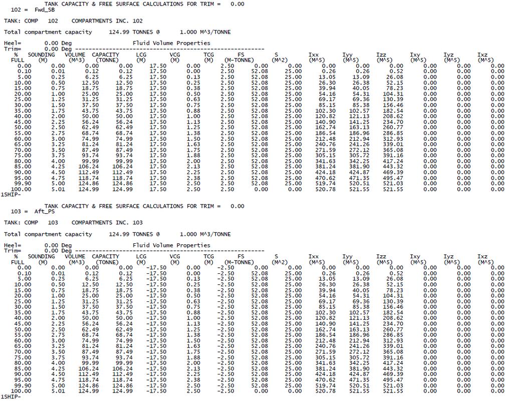
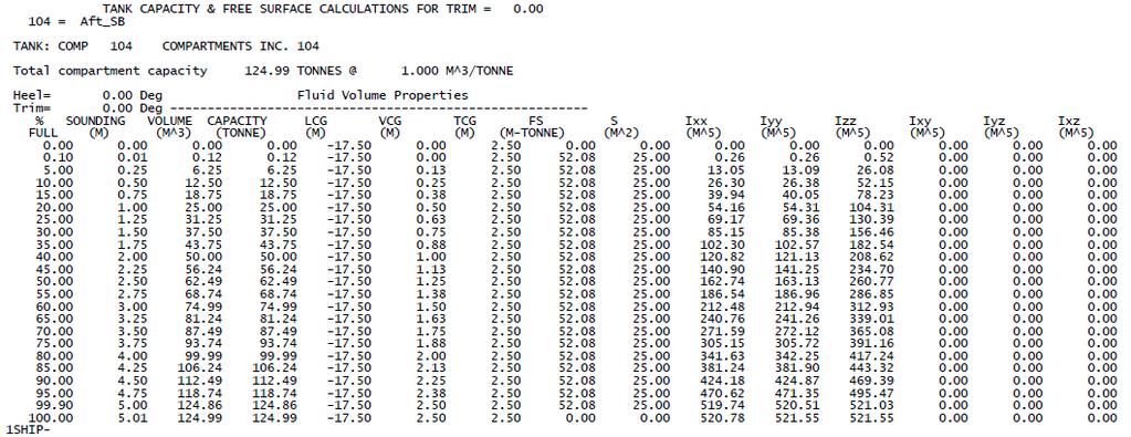
23 Appendix A: Tank Table Output File Verification Matrix DSTO-TR-2968 Table A1 Tank Calibration File data format verification matrix: requirements transposed from the FREDYN interface requirements document presented by Ypma [4] Req ID Document Section Document Section Title Document Sub-Section Document Sub- Section Title Tank Tables 2.1 Heel & Trim Values Tank Tables 2.1 Heel & Trim Values Requirement Verification Method Compliance Verification Evidence Comment The heel definition for each table is defined as positive for Port down The trim definition is defined as positive for stern down Tank Tables 2.2 Volume Range The contents of a single tank have to be described by a percentage ranging from 0% (empty tank) to 100% (full tank) Tank Tables 2.3 Free Surface Area Column Tank Tables 2.4 Tank Mass Moment of Inertia Columns Each tank-table shall have an additional column giving the free surface area as a function of the filling percentage. Each tank-table shall have an additional column giving the free surface moment of inertia as a function of the filling percentage. Not assessed Not assessed Not assessed This requirement is in conflict with requirement 2-2 (Table A2). Clarification was sought from MARIN and the outcome is that requirement 2-2 takes precedence [9]. Inspection Compliant For Maxsurf Stability generated output files: 1.00 deg trim [Filename: Maxsurf Stability Tank Table Verification 0 Heel 1 Trim.OUT] and deg trim [Filename: Maxsurf Stability Tank Table Verification 0 Heel -1 Trim.OUT]. With respect to Tank 102 Fwd SB: Where the trim angle is recorded in the output file as (positive) 1 deg, the tank sounding exceeds 5.00 m (the top of the tank) with respect to the sounding tube datum (midships, centreline, keel) indicating that the barge has trimmed upwards at the bow. Conversely, for the recorded trim angle of deg, the tank sounding does not exceed 5.00 m, thus indicating that the barge is trimmed downwards at the bow. Inspection Compliant For Maxsurf Stability generated output files: Observed for all generated files but for evidence 0.00 deg heel, 0.00 deg trim [Filename: Maxsurf Stability Tank Table Verification 0 Heel 0 Trim.OUT]. The tank data is recorded for each tank for varying contents ranging from 0% to 100% full inclusive. The % FULL data is the leading column in the output file for each tank. Inspection Compliant For Maxsurf Stability generated output files: Observed for all generated files but for evidence 0.00 deg heel, 0.00 deg trim [Filename: Maxsurf Stability Tank Table Verification 0 Heel 0 Trim.OUT]. The area of the free surface is recorded in the tank data table. The area of the free surface (denoted as S) is recorded for each tank for all % FULL. The free surface area data is recorded in the ninth (9th) column in the output file for each tank. Inspection Compliant For Maxsurf Stability generated output files: Observed for all generated files but for evidence 0.00 deg heel, 0.00 deg trim [Filename: Maxsurf Stability Tank Table Verification 0 Heel 0 Trim.OUT]. The free surface area moment of inertia is recorded in the tank data table. The free surface area moment of inertia (denoted as FS) is recorded for each tank for all % FULL. The free surface area moment of inertia data is recorded in the eighth (8th) column in the output file for each tank. This convention complies with the SHCP coordinate system reported in Rosborough [10]. No Comment. No Comment. No Comment. 13
24 DSTO-TR-2968 Req ID Document Section Document Section Title Document Sub-Section Document Sub- Section Title Tank Tables 2.4 Tank Mass Moment of Inertia Columns Requirement Verification Method Compliance Verification Evidence Comment The table format will be completed with 6 columns in the following order (left to right): 1. Ixx 2. Iyy 3. Izz 4. Ixy 5. Iyz 6. Ixz Tank Tables 2.5 Summary A single tank-table will have the following columns: FULL SOUNDING VOLUME CAPACITY LCG TCG VCG S Ixx Iyy Izz Ixy Iyz Ixz Tank Tables 2.5 Summary The unit of the mass moment of inertia is given in [m^5] Tank Tables 2.5 Summary The unit of the mass moment of inertia [m^5] has to be calculated as such Geometry Information 3.3 Tank Data For each tank in the XML file there has to be a corresponding tank-table in the tank table file Inspection Compliant For Maxsurf Stability generated output files: Observed for all generated files but for evidence 0.00 deg heel, 0.00 deg trim [Filename: Maxsurf Stability Tank Table Verification 0 Heel 0 Trim.OUT]. The tank mass moments of inertia (Ixx, Iyy, Izz, Ixy, Iyz, Ixz) are recorded in the tank data table in the aforementioned order. The tank mass moments of inertia are recorded for each tank for all % FULL. The tank mass moments of inertia data is recorded in the last six (6) columns in the output file for each tank (Column 10 through 15). Inspection Compliant For Maxsurf Stability generated output files: Observed for all generated files but for evidence 0.00 deg heel, 0.00 deg trim [Filename: Maxsurf Stability Tank Table Verification 0 Heel 0 Trim.OUT]. The tank table contains the following columns (listed in sequence): FULL, SOUNDING, VOLUME, CAPACITY, LCG, VCG, TCG, FS, S, Ixx, Iyy, Izz, Ixy, Iyz, Ixz. Inspection Compliant For Maxsurf Stability generated output files: Observed for all generated files but for evidence 0.00 deg heel, 0.00 deg trim [Filename: Maxsurf Stability Tank Table Verification 0 Heel 0 Trim.OUT]. The tank mass moments of inertia (Ixx, Iyy, Izz, Ixy, Iyz, Ixz) are recorded in the tank data table with the unit of [m^5]. Inspection Compliant Evidence of calculation methods and algorithms has been supplied by the Developer and is presented in Appendix F. The algorithms illustrate the use of the volume moments method for calculating the volume moment of inertia with the result being in the units of m^5. Noting that the 'mass moment of inertia' stated in the requirement is a pseudo-mass and is independent of fluid density, consequently resulting in a m^5 output. Inspection Compliant For Maxsurf Stability generated output files: Observed for all generated files but for evidence 0.00 deg heel, 0.00 deg trim [Filename: Maxsurf Stability Tank Table Verification 0 Heel 0 Trim.OUT]. For each tank in the *.XML file (generated for the Barge using Maxsurf Stability) there is a corresponding tank-table in the tank table (*.OUT) file. No Comment. Note that there is no FS column listed in the requirement [4]. This requirement is assumed to be an as a minimum type requirement. No Comment. No Comment. No Comment. 14
25 Table A2 Tank Calibration File data format verification matrix: requirements transposed from the FREDYN variable definitions and rotation sequence check document presented by Ypma [3] DSTO-TR-2968 Req ID Document Section Document Section Title Tank Table Format Tank Table Format Quality Definition Quality Definition Quality Definition Quality Definition Quality Definition Document Sub-Section Document Sub- Section Title Requirement Verification Method Compliance Verification Evidence Comment SHCP Original The tank tables are generated in Inspection Complies For Maxsurf Stability generated output files: 1.00 deg heel Additional verification the SHCP format. [Filename: Maxsurf Stability Tank Table Verification 1 Heel 0 evidence: the Maxsurf Trim.OUT] the data format contained in the file matches the Stability tank calibration SHCP format presented in Section Table 1 and Section 6.3 output file was Table 2 and the associated Extension described in Section [3] successfully read in, reviewed and processed using the MARIN Tank Table Processor Version SHCP Original Based on the information provided in [3], the following SHCP output body fixed coordinate system is required: The origin occurs at amidhsips, centreline and baseline (keel). The positive directions of the principal axes are: x is positive forward of amidships, y is positive to starboard, z is positive upwards. Table Item 1 Description The filling percentage has to be defined from 0% to 100% Table Item 2 Description Strictly ascending level with increasing volume Inspection Complies For Maxsurf Stability generated output files: 1.00 deg heel [Filename: Maxsurf Stability Tank Table Verification 1 Heel 0 Trim.OUT] and deg heel [Filename: Maxsurf Stability Tank Table Verification -1 Heel 0 Trim.OUT]. With respect to Tank 102 Fwd SB: The output centre of volume for an upright barge condition has positive values of LCG, TCG and VCG indicating that the point of the centre of volume is positive forward of amidships, positive to starboard and positive above the baseline. Inspection Complies For Maxsurf Stability generated output files: Observed for all generated files but for evidence 0.00 deg heel, 0.00 deg trim [Filename: Maxsurf Stability Tank Table Verification 0 Heel 0 Trim.OUT]. The tank data is recorded for each tank for varying contents ranging from 0% to 100% full inclusive. The % FULL data is the leading column in the output file for each tank. Inspection Complies For Maxsurf Stability generated output files: Observed for all generated files but for evidence 0.00 deg heel, 0.00 deg trim [Filename: Maxsurf Stability Tank Table Verification 0 Heel 0 Trim.OUT]. The tank data is recorded for each tank for varying contents ranging from 0% to 100% full inclusive in ascending order. Table Item 3 Description All tables have to be 100% filled Inspection Complies For Maxsurf Stability generated output files: Observed for all generated files but for evidence 0.00 deg heel, 0.00 deg trim [Filename: Maxsurf Stability Tank Table Verification 0 Heel 0 Trim.OUT]. The tank data is recorded for each tank for varying filling values ranging from 0% to 100% inclusive. Table Item 4 Description All tables have to be the same size Table Item 5 Description Compartment info shall be included Inspection Complies For Maxsurf Stability generated output files: Observed for all generated files but for evidence 0.00 deg heel, 0.00 deg trim [Filename: Maxsurf Stability Tank Table Verification 0 Heel 0 Trim.OUT]. The tank tables generated in the tank calibration output file are of identical size for all tanks/tables. Inspection Complies For Maxsurf Stability generated output files: Observed for all generated files but for evidence 0.00 deg heel, 0.00 deg trim [Filename: Maxsurf Stability Tank Table Verification 0 Heel 0 Trim.OUT]. The compartment information is contained in the output file under the header INPUT COMPARTMENT DESCRIPTIONS (starting at line 14). See Req 1-3 Refer to Appendix C to view the contents of the Maxsurf Stability Tank Table Verification 0 Heel 0 Trim.OUT file. Refer to Appendix C to view the input compartment description data and location within the output file. 15
26 DSTO-TR-2968 Req ID Document Section Document Section Title Quality Definition Quality Definition Document Sub-Section Document Sub- Section Title Requirement Verification Method Compliance Verification Evidence Comment Table Item 6 Description Reliable smooth free surface Analysis and Complies For Maxsurf Stability generated output files: Observed for all Refer to Appendix E for area inspection generated files but for evidence 1.00 deg heel, 0.00 deg trim and the plots of the SB Fwd deg heel, 0.00 deg trim. tank free-surface area The Maxsurf Stability tank calibration files were imported and versus filling percentage processed using the MARIN Tank Table Processor V1.1 and the for starboard heel angles of free-surface area (S) was plotted as a function of filling 1 degree and 60 degrees. percentage. The plotted data possessed a smooth form and the smoothness of the data was found to be reliable as it was observed for a range of heel and trim conditions. Table Item 7 Description tanktableprocessor application is the format checker Execution inspection and Complies For Maxsurf Stability generated output files: Observed for all generated files but for evidence 0.00 deg heel, 0.00 deg trim [Filename: Maxsurf Stability Tank Table Verification 0 Heel 0 Trim.OUT]. All MARIN barge tank calibration files generated using Maxsurf Stability were successfully opened, reviewed and processed using Tank Table Processor Version
27 Appendix B: Maxsurf Stability Tank Calibration Output File Comparison with Paramarine V7.1 Data DSTO-TR-2968 B.1. Comparison of Maxsurf Stability against Paramarine V7.1: Volume, Sounding, LCG, VCG and TCG Table B1 SB FWD Tank at 0.10% Full. Maxsurf Stability Advanced: V Paramarine V7.1 Relative Error Heel [deg] Trim [deg] [m 3 LCG [m] VCG [m] TCG [m] ] [m] [m 3 LCG [m] VCG [m] TCG [m] ] [m] [%] [%] LCG [%] VCG [%] TCG [%] Table B2 SB FWD Tank at 25% Full. Maxsurf Stability Advanced: V Paramarine V7.1 Relative Error Heel [deg] Trim [deg] [m 3 LCG [m] VCG [m] TCG [m] ] [m] [m 3 LCG [m] VCG [m] TCG [m] ] [m] [%] [%] LCG [%] VCG [%] TCG [%] Table B3 SB FWD Tank at 50% Full. Maxsurf Stability Advanced: V Paramarine V7.1 Relative Error Heel [deg] Trim [deg] [m 3 LCG [m] VCG [m] TCG [m] ] [m] [m 3 LCG [m] VCG [m] TCG [m] ] [m] [%] [%] LCG [%] VCG [%] TCG [%] Table B4 SB FWD Tank at 75% Full. Maxsurf Stability Advanced: V Paramarine V7.1 Relative Error Heel [deg] Trim [deg] [m 3 LCG [m] VCG [m] TCG [m] ] [m] [m 3 LCG [m] VCG [m] TCG [m] ] [m] [%] [%] LCG [%] VCG [%] TCG [%]
28 DSTO-TR-2968 Table B5 SB FWD Tank at 99.9% Full. Maxsurf Stability Advanced: V Paramarine V7.1 Relative Error Heel [deg] Trim [deg] [m 3 LCG [m] VCG [m] TCG [m] ] [m] [m 3 LCG [m] VCG [m] TCG [m] ] [m] [%] [%] LCG [%] VCG [%] TCG [%] B.2. Comparison of Maxsurf Stability against Paramarine V7.1: Free-Surface Moment and Free-Surface Area Table B6 Table B7 Table B8 SB FWD Tank at 0.10% Full. Maxsurf Stability Advanced: V Paramarine V7.1 Relative Error Heel [deg] Trim [deg] Free-Surface Moment [m-tonne] Free-Surface Area [m 2 Free-Surface Moment ] [m-tonne] Free-Surface Area [m 2 Free-Surface Moment [%] ] Free-Surface Area [%] Cannot Be Assessed Cannot Be Assessed Cannot Be Assessed Cannot Be Assessed Cannot Be Assessed 0.24 SB FWD Tank at 25% Full. Maxsurf Stability Advanced: V Paramarine V7.1 Relative Error Heel [deg] Trim [deg] Free-Surface Moment [m-tonne] Free-Surface Area [m 2 Free-Surface Moment ] [m-tonne] Free-Surface Area [m 2 Free-Surface Moment [%] ] Free-Surface Area [%] Cannot Be Assessed Cannot Be Assessed Cannot Be Assessed Cannot Be Assessed Cannot Be Assessed 0.00 SB FWD Tank at 50% Full. Maxsurf Stability Advanced: V Paramarine V7.1 Relative Error Heel [deg] Trim [deg] Free-Surface Moment [m-tonne] Free-Surface Area [m 2 Free-Surface Moment ] [m-tonne] Free-Surface Area [m 2 Free-Surface Moment [%] ] Free-Surface Area [%] Cannot Be Assessed Cannot Be Assessed Cannot Be Assessed Cannot Be Assessed Cannot Be Assessed
29 Table B9 SB FWD Tank at 75% Full. Maxsurf Stability Advanced: V Paramarine V7.1 Relative Error Heel [deg] Trim [deg] Free-Surface Moment [m-tonne] Free-Surface Area [m 2 Free-Surface Moment ] [m-tonne] Free-Surface Area [m 2 Free-Surface Moment [%] ] Free-Surface Area [%] Cannot Be Assessed Cannot Be Assessed Cannot Be Assessed Cannot Be Assessed Cannot Be Assessed 0.00 Table B10 SB FWD Tank at 99.9% Full. Maxsurf Stability Advanced: V Paramarine V7.1 Relative Error Heel [deg] Trim [deg] Free-Surface Moment [m-tonne] Free-Surface Area [m 2 Free-Surface Moment ] [m-tonne] Free-Surface Area [m 2 Free-Surface Moment [%] ] Free-Surface Area [%] Cannot Be Assessed Cannot Be Assessed Cannot Be Assessed Cannot Be Assessed Cannot Be Assessed DSTO-TR-2968 B.3. Comparison of Maxsurf Stability against Paramarine V7.1: Volume moments of inertia (Ixx, Iyy and Izz) and Product moments of inertia (Ixy, Iyz and Ixz) Table B11 SB FWD Tank at 0.10% Full. Maxsurf Stability Advanced: V Paramarine V7.1 Relative Error Heel Trim [deg] [deg] I xx [m 5 ] I yy [m 5 ] I zz [m 5 ] I xy [m 5 ] I yz [m 5 ] I xz [m 5 ] I xx [m 5 ] I yy [m 5 ] I zz [m 5 ] I xy [m 5 ] I yz [m 5 ] I xz [m 5 ] I xx [%] I yy [%] I zz [%] I xy [%] I yz [%] I xz [%] Table B12 SB FWD Tank at 25% Full. Maxsurf Stability Advanced: V Paramarine V7.1 Relative Error Heel Trim [deg] [deg] I xx [m 5 ] I yy [m 5 ] I zz [m 5 ] I xy [m 5 ] I yz [m 5 ] I xz [m 5 ] I xx [m 5 ] I yy [m 5 ] I zz [m 5 ] I xy [m 5 ] I yz [m 5 ] I xz [m 5 ] I xx [%] I yy [%] I zz [%] I xy [%] I yz [%] I xz [%] Table B13 SB FWD Tank at 50% Full. Maxsurf Stability Advanced: V Paramarine V7.1 Relative Error Heel Trim [deg] [deg] I xx [m 5 ] I yy [m 5 ] I zz [m 5 ] I xy [m 5 ] I yz [m 5 ] I xz [m 5 ] I xx [m 5 ] I yy [m 5 ] I zz [m 5 ] I xy [m 5 ] I yz [m 5 ] I xz [m 5 ] I xx [%] I yy [%] I zz [%] I xy [%] I yz [%] I xz [%]
30 DSTO-TR-2968 Table B14 SB FWD Tank at 75% Full. Maxsurf Stability Advanced: V Paramarine V7.1 Relative Error Heel Trim [deg] [deg] I xx [m 5 ] I yy [m 5 ] I zz [m 5 ] I xy [m 5 ] I yz [m 5 ] I xz [m 5 ] I xx [m 5 ] I yy [m 5 ] I zz [m 5 ] I xy [m 5 ] I yz [m 5 ] I xz [m 5 ] I xx [%] I yy [%] I zz [%] I xy [%] I yz [%] I xz [%] Table B15 SB FWD Tank at 99.9% Full. Maxsurf Stability Advanced: V Paramarine V7.1 Relative Error Heel Trim [deg] [deg] I xx [m 5 ] I yy [m 5 ] I zz [m 5 ] I xy [m 5 ] I yz [m 5 ] I xz [m 5 ] I xx [m 5 ] I yy [m 5 ] I zz [m 5 ] I xy [m 5 ] I yz [m 5 ] I xz [m 5 ] I xx [%] I yy [%] I zz [%] I xy [%] I yz [%] I xz [%]
31 Appendix C: Maxsurf Stability Tank Calibration Output File Comparison with Rhinoceros 3D V4.0 Data DSTO-TR-2968 C.1. Comparison of Rhinoceros 3D V4.0 against Maxsurf Stability: Volume, Sounding, LCG, VCG and TCG Table C1 SB FWD Tank at 0.10% Full. Rhinoceros V4.0 SR9 Maxsurf Stability Advanced: V Relative Error Heel [deg] Trim [deg] [m 3 LCG [m] VCG [m] TCG [m] ] [m] [m 3 LCG [m] VCG [m] TCG [m] ] [m] [%] [%] LCG [%] VCG [%] TCG [%] Table C2 SB FWD Tank at 25% Full. Rhinoceros V4.0 SR9 Maxsurf Stability Advanced: V Relative Error Heel [deg] Trim [deg] [m 3 LCG [m] VCG [m] TCG [m] ] [m] [m 3 LCG [m] VCG [m] TCG [m] ] [m] [%] [%] LCG [%] VCG [%] TCG [%] Table C3 SB FWD Tank at 50% Full. Rhinoceros V4.0 SR9 Maxsurf Stability Advanced: V Relative Error Heel [deg] Trim [deg] [m 3 LCG [m] VCG [m] TCG [m] ] [m] [m 3 LCG [m] VCG [m] TCG [m] ] [m] [%] [%] LCG [%] VCG [%] TCG [%] Table C4 SB FWD Tank at 75% Full. Rhinoceros V4.0 SR9 Maxsurf Stability Advanced: V Relative Error Heel [deg] Trim [deg] [m 3 LCG [m] VCG [m] TCG [m] ] [m] [m 3 LCG [m] VCG [m] TCG [m] ] [m] [%] [%] LCG [%] VCG [%] TCG [%]
32 DSTO-TR-2968 Table C5 SB FWD Tank at 99.9% Full. Rhinoceros V4.0 SR9 Maxsurf Stability Advanced: V Relative Error Heel [deg] Trim [deg] [m 3 LCG [m] VCG [m] TCG [m] ] [m] [m 3 LCG [m] VCG [m] TCG [m] ] [m] [%] [%] LCG [%] VCG [%] TCG [%] C.2. Comparison of Rhinoceros 3D V4.0 against Maxsurf Stability: Free-Surface Moment and Free-Surface Area Table C6 SB FWD Tank at 0.10% Full. Rhinoceros V4.0 SR9 Maxsurf Stability Advanced: V Relative Error Heel [deg] Trim [deg] Free-Surface Moment [m-tonne] Free-Surface Area [m 2 Free-Surface Moment ] [m-tonne] Free-Surface Area [m 2 Free-Surface Moment [%] ] Free-Surface Area [%] Table C7 SB FWD Tank at 25% Full. Rhinoceros V4.0 SR9 Maxsurf Stability Advanced: V Relative Error Heel [deg] Trim [deg] Free-Surface Moment [m-tonne] Free-Surface Area [m 2 Free-Surface Moment ] [m-tonne] Free-Surface Area [m 2 Free-Surface Moment [%] ] Free-Surface Area [%] Table C8 SB FWD Tank at 50% Full. Rhinoceros V4.0 SR9 Maxsurf Stability Advanced: V Relative Error Heel [deg] Trim [deg] Free-Surface Moment [m-tonne] Free-Surface Area [m 2 Free-Surface Moment ] [m-tonne] Free-Surface Area [m 2 Free-Surface Moment [%] ] Free-Surface Area [%] Table C9 22 SB FWD Tank at 75% Full. Rhinoceros V4.0 SR9 Maxsurf Stability Advanced: V Relative Error Heel [deg] Trim [deg] Free-Surface Moment [m-tonne] Free-Surface Area [m 2 Free-Surface Moment ] [m-tonne] Free-Surface Area [m 2 Free-Surface Moment [%] ] Free-Surface Area [%]
33 DSTO-TR-2968 Table C10 SB FWD Tank at 99.9% Full. Rhinoceros V4.0 SR9 Maxsurf Stability Advanced: V Relative Error Heel [deg] Trim [deg] Free-Surface Moment [m-tonne] Free-Surface Area [m 2 Free-Surface Moment ] [m-tonne] Free-Surface Area [m 2 Free-Surface Moment [%] ] Free-Surface Area [%] Note that the method of calculating the tank free-surface moment data presented under the Rhinoceros 3D column involved using the tank s free-surface width and length dimensions measured directly from the Rhinoceros 3D solid model and applying the standard formula: Free-Surface = fluid free-surface moment of inertia (m 4 ) x density of the fluid in the tank (t/m 3 ). As previously noted, the density of the fluid in the tanks is 1 t/m 3 (fresh water). C.3. Comparison of Rhinoceros 3D V4.0 against Maxsurf Stability: Volume moments of inertia (Ixx, Iyy and Izz) and Product moments of inertia (Ixy, Iyz and Ixz) Table C11 SB FWD Tank at 0.10% Full. Rhinoceros V4.0 SR9 Maxsurf Stability Advanced: V Relative Error Heel Trim [deg] [deg] I xx [m 5 ] I yy [m 5 ] I zz [m 5 ] I xy [m 5 ] I yz [m 5 ] I xz [m 5 ] I xx [m 5 ] I yy [m 5 ] I zz [m 5 ] I xy [m 5 ] I yz [m 5 ] I xz [m 5 ] I xx [%] I yy [%] I zz [%] I xy [%] I yz [%] I xz [%] Table C12 SB FWD Tank at 25% Full. Rhinoceros V4.0 SR9 Maxsurf Stability Advanced: V Relative Error Heel Trim [deg] [deg] I xx [m 5 ] I yy [m 5 ] I zz [m 5 ] I xy [m 5 ] I yz [m 5 ] I xz [m 5 ] I xx [m 5 ] I yy [m 5 ] I zz [m 5 ] I xy [m 5 ] I yz [m 5 ] I xz [m 5 ] I xx [%] I yy [%] I zz [%] I xy [%] I yz [%] I xz [%] Table C13 SB FWD Tank at 50% Full. Rhinoceros V4.0 SR9 Maxsurf Stability Advanced: V Relative Error Heel Trim [deg] [deg] I xx [m 5 ] I yy [m 5 ] I zz [m 5 ] I xy [m 5 ] I yz [m 5 ] I xz [m 5 ] I xx [m 5 ] I yy [m 5 ] I zz [m 5 ] I xy [m 5 ] I yz [m 5 ] I xz [m 5 ] I xx [%] I yy [%] I zz [%] I xy [%] I yz [%] I xz [%]
34 DSTO-TR-2968 Table C14 SB FWD Tank at 75% Full. Rhinoceros V4.0 SR9 Maxsurf Stability Advanced: V Relative Error Heel Trim [deg] [deg] I xx [m 5 ] I yy [m 5 ] I zz [m 5 ] I xy [m 5 ] I yz [m 5 ] I xz [m 5 ] I xx [m 5 ] I yy [m 5 ] I zz [m 5 ] I xy [m 5 ] I yz [m 5 ] I xz [m 5 ] I xx [%] I yy [%] I zz [%] I xy [%] I yz [%] I xz [%] Table C15 SB FWD Tank at 99.9% Full. Rhinoceros V4.0 SR9 Maxsurf Stability Advanced: V Relative Error Heel Trim [deg] [deg] I xx [m 5 ] I yy [m 5 ] I zz [m 5 ] I xy [m 5 ] I yz [m 5 ] I xz [m 5 ] I xx [m 5 ] I yy [m 5 ] I zz [m 5 ] I xy [m 5 ] I yz [m 5 ] I xz [m 5 ] I xx [%] I yy [%] I zz [%] I xy [%] I yz [%] I xz [%]
35 Appendix D: Verification Reference Maxsurf Stability Tank Calibration File DSTO-TR-2968 D.1. Maxsurf Stability Tank Calibration output file (*.OUT): MARIN barge test case in an upright (zero heel and trim) condition 25
36 DSTO-TR
37 DSTO-TR
38 DSTO-TR-2968 Appendix E: Tank Table Processor Plot of Maxsurf Stability Generated Free-Surface Area Data Figure E1 Tank Table Processor plot of SB Fwd tank free-surface area (S) as a function of filling percentage for a 1 degree heel to starboard condition. Figure E2 Tank Table Processor plot of SB Fwd tank free-surface area (S) as a function of filling percentage for a 60 degree heel to starboard condition. 28
 (Ypma [3]).")
39 DSTO-TR-2968 Figure E3 Tank Table Processor plot of tank free-surface area (S) as a function of filling percentage for a combined 8 degree heel to port and 2 degree trim by the bow condition. Plot indicates the undesirable and unacceptable lack of smoothness in the tank table data (shown as the blue line) (Ypma [3]). 29
40 DSTO-TR-2968 Appendix F: Maxsurf Stability Calculation Method: Second Moments of Inertia The following hand-written transcript was provided by the developers of Maxsurf Stability (Formation Design Systems) to DSTO on request. The transcript details the method programmed in Maxsurf Stability to calculate the tank second moments of inertia. 30
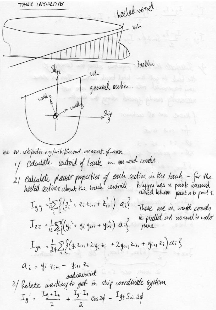
41 DSTO-TR
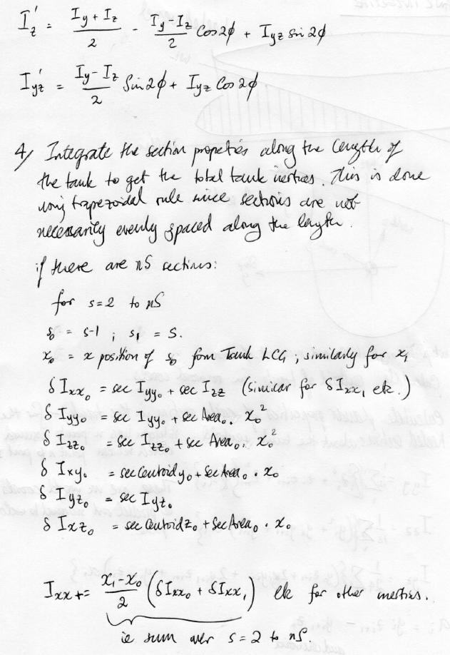
42 DSTO-TR
Manipulator Dynamics 2. Instructor: Jacob Rosen Advanced Robotic - MAE 263D - Department of Mechanical & Aerospace Engineering - UCLA
 Manipulator Dynamics 2 Forward Dynamics Problem Given: Joint torques and links geometry, mass, inertia, friction Compute: Angular acceleration of the links (solve differential equations) Solution Dynamic
Transport Analysis Report Full Stability Analysis. Project EXAMPLE PROJECT DEMO RUN FOR REVIEW. Client ORCA OFFSHORE
 ONLINE MARINE ENGINEERING Transport Analysis Report Full Stability Analysis Project EXAMPLE PROJECT DEMO RUN FOR REVIEW Client ORCA OFFSHORE Issue Date 18/11/2010 Report reference number: Herm-18-Nov-10-47718
PLEASURE VESSEL VIBRATION AND NOISE FINITE ELEMENT ANALYSIS
 PLEASURE VESSEL VIBRATION AND NOISE FINITE ELEMENT ANALYSIS 1 Macchiavello, Sergio *, 2 Tonelli, Angelo 1 D Appolonia S.p.A., Italy, 2 Rina Services S.p.A., Italy KEYWORDS pleasure vessel, vibration analysis,
SHIP BUOYANCY AND STABILITY. Lecture 02 Ship equilibrium and introduction to ship hydrostatics
 SHIP BUOYANCY AND STABILITY Lecture 02 Ship equilibrium and introduction to ship hydrostatics 1 Literature J. Matusiak: Laivan kelluvuus ja vakavuus Biran A. B., Ship Hydrostatics and Stability, 2003 J.
Calibration of Anemometers used in the Ship Survivability Enhancement Program
 Calibration of Anemometers used in the Ship Survivability Enhancement Program G.I. Gamble and F. Marian Maritime Platforms Division Aeronautical and Maritime Research Laboratory DSTO-TN-00 ABSTRACT Part
Hydrostatics and Stability Dr. Hari V Warrior Department of Ocean Engineering and Naval Architecture Indian Institute of Technology, Kharagpur
 Hydrostatics and Stability Dr. Hari V Warrior Department of Ocean Engineering and Naval Architecture Indian Institute of Technology, Kharagpur Module No. # 01 Lecture No. # 09 Free Surface Effect In the
Numerical Study of the Roll Decay of Intact and Damaged Ships by Q. Gao and D. Vassalos
 Session 7 Stability of Damaged Ships Numerical Simulation of Progressive Flooding and Capsize Numerical Study of the Roll Decay of Intact and Damaged Ships by Q. Gao and D. Vassalos Qiuxin Gao and Dracos
Hydrostatic and Stability IN A NUTSHELL. of Floating Structures. Compendium. Relevant to Questions in Exam. Robert Bronsart
 Hydrostatic and Stability of Floating Structures IN A NUTSHELL Compendium Relevant to Questions in Exam Robert Bronsart Version Date Comment 2.21 September 2015 minor corrections Author: Robert Bronsart
Capstan Design (Capstan Power) for Berthing
 for Berthing") What does this Excel Sheet do? Capstan Design (Capstan Power) for Berthing This Excel sheet helps the user obtain the required Capstan Line Pull and Capstan Power for berthing operations The Capstan can
What does this Excel Sheet do? Capstan Design (Capstan Power) for Berthing This Excel sheet helps the user obtain the required Capstan Line Pull and Capstan Power for berthing operations The Capstan can
S19 S19. (1997) (Rev ) (Rev. 2 Feb. 1998) (Rev.3 Jun. 1998) (Rev.4 Sept. 2000) (Rev.5 July 2004) S Application and definitions
 (Rev ) (Rev. 2 Feb. 1998) (Rev.3 Jun. 1998) (Rev.4 Sept. 2000) (Rev.5 July 2004) S Application and definitions") (1997) (Rev. 1 1997) (Rev. Feb. 1998) (Rev.3 Jun. 1998) (Rev.4 Sept. 000) (Rev.5 July 004) Evaluation of Scantlings of the Transverse Watertight Corrugated Bulkhead between Cargo Holds Nos. 1 and, with
(1997) (Rev. 1 1997) (Rev. Feb. 1998) (Rev.3 Jun. 1998) (Rev.4 Sept. 000) (Rev.5 July 004) Evaluation of Scantlings of the Transverse Watertight Corrugated Bulkhead between Cargo Holds Nos. 1 and, with
Optimal Design of FPSO Vessels
 November 2, 201 Optimal Design of FPSO Vessels Ezebuchi Akandu PhD, MTech, BTech, COREN, RINA, MNSE Department of Marine Engineering, Rivers State University, Port Harcourt, Nigeria akandu.ezebuchi@ust.edu.ng
Hong Kong Institute of Vocational Education (Tsing Yi) Higher Diploma in Civil Engineering Structural Mechanics. Chapter 2 SECTION PROPERTIES
 Higher Diploma in Civil Engineering Structural Mechanics. Chapter 2 SECTION PROPERTIES") Section Properties Centroid The centroid of an area is the point about which the area could be balanced if it was supported from that point. The word is derived from the word center, and it can be though
Section Properties Centroid The centroid of an area is the point about which the area could be balanced if it was supported from that point. The word is derived from the word center, and it can be though
Requirements for Computational Methods to be sed for the IMO Second Generation Intact Stability Criteria
 Proceedings of the 1 th International Conference on the Stability of Ships and Ocean Vehicles, 14-19 June 15, Glasgow, UK Requirements for Computational Methods to be sed for the IMO Second Generation
STABILITY AND TRIM OF MARINE VESSELS. Massachusetts Institute of Technology, Subject 2.017
 STABILITY AND TRIM OF MARINE VESSELS Concept of Mass Center for a Rigid Body Centroid the point about which moments due to gravity are zero: 6 g m i (x g x i )= 0 Æ x = 6m i x i / 6m i = 6m i x i / M g
Longitudinal strength standard
 (1989) (Rev. 1 199) (Rev. Nov. 001) Longitudinal strength standard.1 Application This requirement applies only to steel ships of length 90 m and greater in unrestricted service. For ships having one or
Department of Aerospace and Ocean Engineering Graduate Study Specialization in Ocean Engineering. Written Preliminary Examination Information
 Department of Aerospace and Ocean Engineering Graduate Study Specialization in Ocean Engineering Written Preliminary Examination Information Faculty: Professors W. Neu, O. Hughes, A. Brown, M. Allen Test
Dessi, D., D Orazio, D.
 CORRELATION OF MODEL-SCALE AND FULL-SCALE DATA: SENSOR VALIDATION AND ELASTIC SCALING EVALUATION Dessi, D., D Orazio, D. INSEAN-CNR Rome - Italy 1 Project structure hydroelastic side This work was funded
Determination of Locally Varying Directions through Mass Moment of Inertia Tensor
 Determination of Locally Varying Directions through Mass Moment of Inertia Tensor R. M. Hassanpour and C.V. Deutsch Centre for Computational Geostatistics Department of Civil and Environmental Engineering
SHIP BUOYANCY AND STABILITY. Lecture 03 Ship initial stability
 SHIP BUOYANCY AND STABILITY Lecture 3 Ship initial stability 1 Literature J. Matusiak: Laivan kelluvuus ja vakavuus Biran A. B., Ship Hydrostatics and Stability, 23 J. Matusiak: Short Introduction to Ship
RULES FOR THE CONSTRUCTION AND CLASSIFICATION OF SHIPS IDENTIFIED BY THEIR MISSIONS DREDGERS AND MUD BARGES CHAPTERS CHAPTERS SCOPE
 PARTE II RULES FOR THE CONSTRUCTION AND CLASSIFICATION OF SHIPS IDENTIFIED BY THEIR MISSIONS TÍTULO 43 DREDGERS AND MUD BARGES SECTION 2 STRUCTURE CHAPTERS SECTION 2 STRUCTURE CHAPTERS A B C SCOPE DOCUMENTS,
Reliability assessment of ship powering performance extrapolations using Monte Carlo methods
 Third International Symposium on Marine Propulsors smp 13, Launceston, Tasmania, Australia, May 2013 Reliability assessment of ship powering performance extrapolations using Monte Carlo methods Iwan M.
RULES FOR CLASSIFICATION. Ships. Part 3 Hull Chapter 4 Loads. Edition January 2017 DNV GL AS
 RULES FOR CLASSIFICATION Ships Edition January 2017 Part 3 Hull Chapter 4 The content of this service document is the subject of intellectual property rights reserved by ("DNV GL"). The user accepts that
Seakeeping characteristics of intact and damaged ship in the Adriatic Sea
 Towards Green Marine Technology and Transport Guedes Soares, Dejhalla & Pavleti (Eds) 2015 Taylor & Francis Group, London, ISBN 978-1-138-02887-6 Seakeeping characteristics of intact and damaged ship in
Safe Struck Ship (3S):Software Package for Structural analysis of collision between ships
:Software Package for Structural analysis of collision between ships") Port Said Engineering Research Journal Faculty of Engineering - Port Said University Volume 16 No. 2 pp.: 68:79 Safe Struck Ship (3S):Software Package for Structural analysis of collision between ships
Port Said Engineering Research Journal Faculty of Engineering - Port Said University Volume 16 No. 2 pp.: 68:79 Safe Struck Ship (3S):Software Package for Structural analysis of collision between ships
Space engineering. Structural finite element models. ECSS-E-ST-32-03C 31 July 2008
 ECSS-E-ST-32-03C Space engineering Structural finite element models ECSS Secretariat ESA-ESTEC Requirements & Standards Division Noordwijk, The Netherlands Foreword This Standard is one of the series of
Evaluation of Scantlings of Corrugated Transverse Watertight Bulkheads in Non-CSR Bulk Carriers Considering Hold Flooding
 (1997) (Rev.1 1997) (Rev.1.1 Mar 1998 /Corr.1) (Rev. Sept 000) (Rev.3 eb 001) (Rev.4 Nov 001) (Rev.5 July 003) (Rev.6 July 004) (Rev.7 eb 006) (Corr.1 Oct 009) (Rev.8 May 010) (Rev.9 Apr 014) Evaluation
Welcome to the Ship Resistance Predictor! The total calm water resistance is given by:
 Welcome to the Ship Resistance Predictor! What does this Excel Sheet do? This Excel sheet helps you calculate the Total Calm Water Resistance for a Ship at a given forward speed It also calculates from
Lecture 8. Stress Strain in Multi-dimension
 Lecture 8. Stress Strain in Multi-dimension Module. General Field Equations General Field Equations [] Equilibrium Equations in Elastic bodies xx x y z yx zx f x 0, etc [2] Kinematics xx u x x,etc. [3]
Development of formulas allowing to predict hydrodynamic responses of inland vessels operated within the range of navigation 0.6 Hs 2.
 Gian Carlo Matheus Torres 6 th EMship cycle: October 2015 February 2017 Master Thesis Development of formulas allowing to predict hydrodynamic responses of inland vessels operated within the range of navigation
Wuchang Shipbuilding Industry Co., Ltd. China Shipbuilding Industry Corporation
 Safety Assessments for Anchor Handling Conditions of Multi-purpose Platform Work Vessels Reporter:Yu Wang Wuchang Shipbuilding Industry Co., Ltd. China Shipbuilding Industry Corporation 2009.12.04 0 Outline
Tensor Transformations and the Maximum Shear Stress. (Draft 1, 1/28/07)
") Tensor Transformations and the Maximum Shear Stress (Draft 1, 1/28/07) Introduction The order of a tensor is the number of subscripts it has. For each subscript it is multiplied by a direction cosine array
Tensor Transformations and the Maximum Shear Stress (Draft 1, 1/28/07) Introduction The order of a tensor is the number of subscripts it has. For each subscript it is multiplied by a direction cosine array
SPECIAL CONDITION. Water Load Conditions. SPECIAL CONDITION Water Load Conditions
 Doc. No. : SC-CVLA.051-01 Issue : 1d Date : 04-Aug-009 Page : 1 of 13 SUBJECT : CERTIFICATION SPECIFICATION : VLA.51 PRIMARY GROUP / PANEL : 03 (Structure) SECONDARY GROUPE / PANEL : -- NATURE : SCN VLA.51
Urban Canopy Tool User Guide `bo`
 Urban Canopy Tool User Guide `bo` ADMS Urban Canopy Tool User Guide Version 2.0 June 2014 Cambridge Environmental Research Consultants Ltd. 3, King s Parade Cambridge CB2 1SJ UK Telephone: +44 (0)1223
SAFEHULL-DYNAMIC LOADING APPROACH FOR VESSELS
 Guide for SafeHull- Dynamic Loading Approach for Vessels GUIDE FOR SAFEHULL-DYNAMIC LOADING APPROACH FOR VESSELS DECEMBER 2006 (Updated February 2014 see next page) American Bureau of Shipping Incorporated
Sediment Acoustics LONG-TERM GOAL
 Sediment Acoustics Robert D. Stoll Lamont-Doherty Earth Observatory of Columbia University Palisades, New York 10964 phone: (914) 365 8392 fax: (914) 365 8179 email: rdstoll@worldnet.att.net Award #: N00014-94-1-0258
Hydraulic Processes Analysis System (HyPAS)
") Hydraulic Processes Analysis System (HyPAS) by Thad C. Pratt and Daryl S. Cook PURPOSE: This Coastal Engineering Technical Note (CETN) describes a PC-Windows-based system for analyzing, visualizing, and
Hydraulic Processes Analysis System (HyPAS) by Thad C. Pratt and Daryl S. Cook PURPOSE: This Coastal Engineering Technical Note (CETN) describes a PC-Windows-based system for analyzing, visualizing, and
Sailing Performance and Maneuverability of a Traditional Ryukyuan Tribute Ship
 sia Navigation Conference 009 ailing Performance and Maneuverability of a Traditional Ryukyuan Tribute hip by Yutaka MUYM (Kanazawa Institute of Technology) Hikaru YGI (Tokai University ) Yutaka TERO (Tokai
CFD Based Hull Hydrodynamic Forces for Simulation of Ship Manoeuvres
 International Journal on Marine avigation and Safety of Sea Transportation Volume 3 umber 1 March 9 Based Hull Hydrodynamic Forces for Simulation of Ship Manoeuvres T. Tabaczek, T. Gornicz & J. Kulczyk
MEASURING THE COMPLEXITY AND IMPACT OF DESIGN CHANGES
 Presentation Paper Bio Return to Main Menu P R E S E N T A T I O N W4 Wednesday, March 8, 2000 11:00AM MEASURING THE COMPLEXITY AND IMPACT OF DESIGN CHANGES Mike Libassi Intel Corporation International
Programming Project 2: Harmonic Vibrational Frequencies
 Programming Project 2: Harmonic Vibrational Frequencies Center for Computational Chemistry University of Georgia Athens, Georgia 30602 Summer 2012 1 Introduction This is the second programming project
CAPACITY ESTIMATES AND GENERAL ARRANGEMENT
 CAPACITY ESTIMATES AND GENERAL ARRANGEMENT This will verify that sufficient space is available for the amount of cargo to be carried. For capacity ships, it is a primary factor and may be a starting point
Characterization of Geoobjects Continuity using Moments of Inertia
 Characterization of Geoobjects Continuity using Moments of Inertia Saina Lajevardi, Olena Babak, and Clayton V. Deutsch Well-placement is one of the main challenges in reservoir engineering. The connectivity
ASSESSMENT OF STRESS CONCENTRATIONS IN LARGE CONTAINER SHIPS USING BEAM HYDROELASTIC MODEL
 ASSESSMENT OF STRESS CONCENTRATIONS IN LARGE CONTAINER SHIPS USING BEAM HYDROELASTIC MODEL Ivo Senjanović, Nikola Vladimir Faculty of Mechanical Engineering and Naval Architecture, University of Zagreb,
WAMIT-MOSES Hydrodynamic Analysis Comparison Study. JRME, July 2000
 - Hydrodynamic Analysis Comparison Study - Hydrodynamic Analysis Comparison Study JRME, Prepared by Hull Engineering Department J. Ray McDermott Engineering, LLC 1 - Hydrodynamic Analysis Comparison Study
2.1 Background of Piping Stresses
 2 Research Review One of the major additions to Tmin was the inclusion of analysis of a 2-Dimensional vertical piping span. The original plan from Dupont was to include several types of 2-D and 3-D vertical
RULES PUBLICATION NO. 17/P ZONE STRENGTH ANALYSIS OF HULL STRUCTURE OF ROLL ON/ROLL OFF SHIP
 RULES PUBLICATION NO. 17/P ZONE STRENGTH ANALYSIS OF HULL STRUCTURE OF ROLL ON/ROLL OFF SHIP 1995 Publications P (Additional Rule Requirements), issued by Polski Rejestr Statków, complete or extend the
Wave Resistance Prediction of Hard-Chine Catamarans through. Regression Analysis
 Wave Resistance Prediction of Hard-Chine Catamarans through Xuan P. Pham Research Student Dept. of Naval Architecture & Ocean Engineering Australian Maritime College PO Box 986, Launceston, TAS 7250, Australia.
Weighted Stability Index (WSI) Metric Model Mike Libassi Intel Corp 8/11/99
 Metric Model Mike Libassi Intel Corp 8/11/99") Weighted Stability Index (WSI) Metric Model Mike Libassi Intel Corp 8/11/99 Abstract Methods, such as McCabe's Cyclomatic Complexity, have proven that complexity is a reliable predictor of defects. Although
Weighted Stability Index (WSI) Metric Model Mike Libassi Intel Corp 8/11/99 Abstract Methods, such as McCabe's Cyclomatic Complexity, have proven that complexity is a reliable predictor of defects. Although
CARGO STOWAGE AND SECURING
 Resolutions from the 17th Session of the Assembly of IMO, November 1991, as amended CODE OF SAFE PRACTICE FOR CARGO STOWAGE AND SECURING CARGO STOWAGE AND SECURING ANNEX 13. Til bruk i maritime fagskoler
Procedure for Performing Stress Analysis by Means of Finite Element Method (FEM)
") Procedure for Performing Stress Analysis by Means of Finite Element Method (FEM) Colaboração dos engºs Patrício e Ediberto da Petrobras 1. Objective This Technical Specification sets forth the minimum
Procedure for Performing Stress Analysis by Means of Finite Element Method (FEM) Colaboração dos engºs Patrício e Ediberto da Petrobras 1. Objective This Technical Specification sets forth the minimum
The Cambridge Rocketry Simulator User Guide
 The Cambridge Rocketry Simulator User Guide Willem Eerland last updated: October 4, 2016 1 Contents 1 Introduction 3 2 Designing a rocket 3 2.1 Nose cone................................. 3 2.2 Body tube.................................
Sediment Acoustics. Award #: N Thrust Category: High-Frequency LONG-TERM GOAL
 Sediment Acoustics Robert D. Stoll Lamont-Doherty Earth Observatory of Columbia University Palisades, New York 10964 phone: (845) 365 8392 fax: (845) 365 8179 email: stoll@ldeo.columbia.edu Award #: N00014-94-1-0258
RESERVE THALES ALENIA SPACE CHANGE RECORDS ISSUE DATE DESCRIPTION OF CHANGES AUTHOR
 ISSUE : 1 Page : 2/35 CHANGE RECORDS ISSUE DATE DESCRIPTION OF CHANGES AUTHOR 1 03/10/07 Initial issue (MTG-TAF-SA-RS-39) J. VIEILLOT 1 20/09/10 Updated version for kick off : L.OUCHET New reference (MTG-TAF-SA-SS-0039)
An Evaluation and Comparison of Models for Maximum Deflection of Stiffened Plates Using Finite Element Analysis
 Marine Technology, Vol. 44, No. 4, October 2007, pp. 212 225 An Evaluation and Comparison of Models for Maximum Deflection of Stiffened Plates Using Finite Element Analysis Lior Banai 1 and Omri Pedatzur
Modelling stray current interference to shipboard cathodic protection system
 Paper No. 215-6631 Modelling stray current interference to shipboard cathodic protection system Yueping Wang Defence Research and Development Canada Atlantic Research Centre CFB Halifax, Bldg D-2 P.O.
Study of the hydrodynamic flow around a 70m sailing boat for powering, wave pattern and propeller efficiency prediction
 Study of the hydrodynamic flow around a 70m sailing boat for powering, wave pattern and propeller efficiency prediction Romain Baudson Supervisor: Prof. Dario Boote (UNIGE) External Reviewer: Prof. Pierre
I INCH- POUND j MIL-STD-1399(NAVY SECTION 302A 29 February 1988 SUPERSEDING DOD-STD-1399(NAVY) SECTION March 1972 (See 6.3) MILITARY STANDARD
 SECTION March 1972 (See 6.3) MILITARY STANDARD") I INCH- POUND j MIL-STD-1399(NAVY SUPERSEDING DOD-STD-1399(NAVY) SECTION 302 20 March 1972 (See 6.3) MILITARY STANDARD INTERFACE STANDARD FOR SHIPBOARD SYSTEMS SECTION 302 WEATHER ENVIRONMENT AMSC N/A
I INCH- POUND j MIL-STD-1399(NAVY SUPERSEDING DOD-STD-1399(NAVY) SECTION 302 20 March 1972 (See 6.3) MILITARY STANDARD INTERFACE STANDARD FOR SHIPBOARD SYSTEMS SECTION 302 WEATHER ENVIRONMENT AMSC N/A
Practical methodology for inclusion of uplift and pore pressures in analysis of concrete dams
 Practical methodology for inclusion of uplift and pore pressures in analysis of concrete dams Michael McKay 1 and Francisco Lopez 2 1 Dams Engineer, GHD Pty 2 Principal Dams/Structural Engineer, GHD Pty
AS Australian Standard
 AS 2850 1986 Australian Standard Chemical analysis Interlaboratory test programs For determining precision of analytical method(s) Guide to the planning and conduct This Australian standard was prepared
On an Advanced Shipboard Information and Decision-making System for Safe and Efficient Passage Planning
 International Journal on Marine Navigation and Safety of Sea Transportation Volume 2 Number 1 March 28 On an Advanced Shipboard Information and Decision-making System for Safe and Efficient Passage Planning
RULES FOR CLASSIFICATION. Ships. Part 3 Hull Chapter 6 Hull local scantling. Edition January 2017 DNV GL AS
 RULES FOR CLASSIFICATION Ships Edition January 2017 Part 3 Hull Chapter 6 The content of this service document is the subject of intellectual property rights reserved by ("DNV GL"). The user accepts that
NAVGEM Platform Support
 DISTRIBUTION STATEMENT A. Approved for public release; distribution is unlimited. NAVGEM Platform Support Mr. Timothy Whitcomb Naval Research Laboratory 7 Grace Hopper Ave, MS2 Monterey, CA 93943 phone:
Study on Motions of a Floating Body under Composite External Loads
 137 Study on Motions of a Floating Body under Composite External Loads by Kunihiro Ikegami*, Member Masami Matsuura*, Member Summary In the field of marine engineering, various types of floating bodies
Probabilistic Assessment of a Stiffened Carbon Fibre Composite Panel Operating in its Postbuckled Region Authors: Correspondence:
 Probabilistic Assessment of a Stiffened Carbon Fibre Composite Panel Operating in its Postbuckled Region Authors: D. Elder and R. Thomson Cooperative Research Centre for Advanced Composite Structures Limited
Composite Structural Mechanics using MATLAB
 Session 2520 Composite Structural Mechanics using MATLAB Oscar Barton, Jr., Jacob B. Wallace United States Naval Academy Annapolis, Md 21402 Abstract In this paper MATLAB is adopted as the programming
Calculation of hydrodynamic manoeuvring coefficients using viscous-flow calculations
 Calculation of hydrodynamic manoeuvring coefficients using viscous-flow calculations Serge Toxopeus Maritime Research Institute Netherlands (MARIN), Wageningen, The Netherlands Delft University of Technology,
Influence of the Transom-Hollow Length on Wave Resistance
 Summary Influence of the Transom-Hollow Length on Wave Resistance Lawrence J. Doctors The University of New South Wales, Sydney, NSW 2052, Australia Email: L.Doctors@UNSW.edu.au Previous experimental data
Mooring Model for Barge Tows in Lock Chamber
 Mooring Model for Barge Tows in Lock Chamber by Richard L. Stockstill BACKGROUND: Extensive research has been conducted in the area of modeling mooring systems in sea environments where the forcing function
Basic Information on Acceleration Measurements Using the MSR145 and MSR165 Data Loggers
 Basic Information on Acceleration Measurements Using the MSR145 and MSR165 Data Loggers 1 Introduction/Overview Measuring physical impacts is of great importance in many fields of application in order
Client RSK Environment Ltd Job No. J387 Date 19/11/2016. Project: Environmental Survey Location: Otranto Vessel: RV Atlante
 FUGRO OCEANSISMICA S.p.A. GEODETIC PARAMETERS Client RSK Environment Ltd Job No. J387 Date 19/11/216 Project: Environmental Survey Location: Otranto Vessel: RV Atlante WGS-84 Geodetic Parameters Datum
7.3 Design of members subjected to combined forces
 7.3 Design of members subjected to combined forces 7.3.1 General In the previous chapters of Draft IS: 800 LSM version, we have stipulated the codal provisions for determining the stress distribution in
REPORT TYPE Conference Proceedings. 2o xo;ui3s/
 REPORT DOCUMENTATION PAGE Form Approved OMB No. 0704-0188 The public reporting burden for this collection of information is estimated to average 1 hour per response, including the time for reviewing instructions,
VERIFICATION AND VALIDATION OF RESISTANCE AND PROPULSION COMPUTATION
 VERIFICATION AND VALIDATION OF RESISTANCE AND PROPULSION COMPUTATION G. Deng, A. Leroyer, E. Guilmineau, P. Queutey, M. Visonneau & J. Wackers (ECN-LHEEA,CNRS, France) A. del Toro Llorens (Spanish Institution
3GPP TS V ( )
") TS 23.032 V11.0.0 (2012-09) Technical Specification 3rd Generation Partnership Project; Technical Specification Group Services and System Aspects; Universal Geographical Area Description (GAD) (Release
TS 23.032 V11.0.0 (2012-09) Technical Specification 3rd Generation Partnership Project; Technical Specification Group Services and System Aspects; Universal Geographical Area Description (GAD) (Release
Obtaining the Center of Gravity, Volume, Weight and More
 C h a p t e r 10 Obtaining the Center of Gravity, Volume, Weight and More In this chapter, you will learn the following to World Class standards: The Importance of the Center of Gravity The Inquiry Toolbar
Research on Prediction of Ship Manoeuvrability
 Journal of Shipping and Ocean Engineering 8 (08 30-35 doi 0.765/59-5879/08.0.004 D DAVID PUBLISHING Research on Prediction of Ship Manoeuvrability CUI Jian, WU Zixin and CHEN Weimin Shanghai Ship and Shipping
Aviation Weather Routing Tool: A Decision Aid for Manned/Unmanned Aircraft Routing
 Aviation Weather Routing Tool: A Decision Aid for Manned/Unmanned Aircraft Routing Dr. Richard Shirkey Mr. Terry Jameson Battlefield Environment Division Army Research Laboratory, WSMR rshirkeyn@arl.army.mil
Coastal and Hydraulics Laboratory
 SAM Hydraulic Design Package for Channels Coastal and Hydraulics Laboratory William A. Thomas, Ronald R. Copeland, and Dinah N. McComas September 2002 Approved for public release; distribution is unlimited.
Preliminary Comparison of March May Radiosonde Soundings with March May Climatological Profiles for Yuma, Arizona
 ARL-TN-0812 FEB 2017 US Army Research Laboratory Preliminary Comparison of March May Radiosonde Soundings with March May Climatological Profiles for Yuma, Arizona by J Cogan and P Haines NOTICES Disclaimers
ETSI TS V7.0.0 ( )
") TS 101 109 V7.0.0 (1999-07) Technical Specification Digital cellular telecommunications system (Phase 2+); Universal Geographical Area Description (GAD) (GSM 03.32 version 7.0.0 Release 1998) GLOBAL SYSTEM
TS 101 109 V7.0.0 (1999-07) Technical Specification Digital cellular telecommunications system (Phase 2+); Universal Geographical Area Description (GAD) (GSM 03.32 version 7.0.0 Release 1998) GLOBAL SYSTEM
DYNAMIC RESPONSE OF BOX-TYPE SONAR STRUCTURE. Sameer Abdul Azeez and O.R.Nandagopan
 ICSV14 Cairns Australia 9-12 July, 2007 DYNAMIC RESPONSE OF BOX-TYPE SONAR STRUCTURE Sameer Abdul Azeez and O.R.Nandagopan Naval Physical & Oceanographic Laboratory, Kochi, India 682 021 tsonpol@vsnl.com
SWELL RATIO TESTER REPORT FY 2003
 Indian Head Division IHTR 2654 Naval Surface Warfare Center 24 September 2004 Indian Head, MD 20640-5035 SWELL RATIO TESTER REPORT FY 2003 Ralph Gamba Approved for public release; distribution is unlimited.
Experimental Uncertainty (Error) and Data Analysis
 and Data Analysis") E X P E R I M E N T 1 Experimental Uncertainty (Error) and Data Analysis INTRODUCTION AND OBJECTIVES Laboratory investigations involve taking measurements of physical quantities, and the process of taking
E X P E R I M E N T 1 Experimental Uncertainty (Error) and Data Analysis INTRODUCTION AND OBJECTIVES Laboratory investigations involve taking measurements of physical quantities, and the process of taking
Specific Accreditation Guidance
 Specific Accreditation Guidance Materials Characterisation of Metallic Items by X-Ray Fluorescence and Atomic (Arc/Spark) Emission Techniques August 2018 Copyright National Association of Testing Authorities,
NOVEL USES OF CATHODIC PROTECTION SYSTEMS FOR STRUCTURE CONDITION ASSESSMENT. James A. Ellor Elzly Technology Corporation Reston, VA
 NOVEL USES OF CATHODIC PROTECTION SYSTEMS FOR STRUCTURE CONDITION ASSESSMENT James A. Ellor Elzly Technology Corporation Reston, VA jellor@elzly.com And Andrew D. Seelinger Naval Sea Systems Command Washington,
ITTC Recommended Procedures Testing and Extrapolation Methods Resistance Resistance Test
 -0- Page 1 of 11 CONTENTS 1. PURPOSE OF PROCEDURE. PARAMETERS.1 Data Reduction Equations. Definition of ariables 3. DESCRIPTION OF PROCEDURE 3.1 Model and Installation 3.1.1 Model 3.1. Test condition 3.1.3
MARINE VESSEL FRONTIER ANGEL & MARINE VESSEL EL CONDOR PASA
 MARINE VESSEL FRONTIER ANGEL & MARINE VESSEL EL CONDOR PASA ANALYSIS OF AIR QUALITY MONITORING DATA ASSOCIATED WITH BULK NICKEL SULFIDE SHIP-LOADING ON 18 TH TO 20 TH FEBRUARY 2010 Revision Prepared Reviewed
Comparison of Thruster Axis Tilting versus Nozzle Tilting on the Propeller-Hull Interactions for a Drillship at DP-Conditions
 DYNAMIC POSITIONING CONFERENCE October 12-13, 2010 Thrusters Comparison of Thruster Axis Tilting versus Nozzle Tilting on the Propeller-Hull Interactions for a Drillship at DP-Conditions Michael Palm,
Omega Chemicals Emissions Testing Report
 Omega Chemicals 18-Feb-2015 Doc No. 60336610_1.1_RPT Omega Chemicals Emissions Testing Report February 2015 NATA ACCREDITATION No. 2778 (14391) Accredited for compliance with ISO/IEC 17025 This document
SEAKEEPING NUMERICAL ANALYSIS IN IRREGULAR WAVES OF A CONTAINERSHIP
 Mechanical Testing and Diagnosis ISSN 47 9635, 13 (III), Volume 1, pp. 19-31 SEAKEEPING NUMERICAL ANALYSIS IN IRREGULAR WAVES OF A CONTAINERSHIP Carmen GASPAROTTI, Eugen RUSU University of Galati, ROMANIA
Viscous Damping of Vessels Moored in Close Proximity of Another Object
 Proceedings of The Fifteenth (5) International Offshore and Polar Engineering Conference Seoul, Korea, June 9 4, 5 Copyright 5 by The International Society of Offshore and Polar Engineers ISBN -885-4-8
MEASUREMENTS OF SOUND ABSORPTION TIMBERCRETE
 A.B.N. 73 107 291 494 C O N S U L T I N G A C O U S T I C A L E N G I N E E R S MEASUREMENTS OF SOUND ABSORPTION TIMBERCRETE 100 mm ANCIENT STONE BRICK REPORT NUMBER: 4546-2 PREPARED FOR: Timbercrete Pty
Hydraulic Processes Analysis System (HyPAS)
") Hydraulic Processes Analysis System (HyPAS) by Thad C. Pratt and Daryl S. Cook PURPOSE: This Coastal Engineering Technical Note (CETN) describes a PC-Windows-based system for analyzing, visualizing, and
Hydraulic Processes Analysis System (HyPAS) by Thad C. Pratt and Daryl S. Cook PURPOSE: This Coastal Engineering Technical Note (CETN) describes a PC-Windows-based system for analyzing, visualizing, and
Chapter IV. (Ship Hydro-Statics & Dynamics) Floatation & Stability
 Floatation & Stability") Chapter V (Ship Hydro-Statics & Dynamics) Floatation & Stability 4.1 mportant Hydro-Static Curves or Relations (see Fig. 4.11 at p44 & handout) Displacement Curves (displacement [molded, total] vs. draft,
Chapter V (Ship Hydro-Statics & Dynamics) Floatation & Stability 4.1 mportant Hydro-Static Curves or Relations (see Fig. 4.11 at p44 & handout) Displacement Curves (displacement [molded, total] vs. draft,
Improved Parameterizations Of Nonlinear Four Wave Interactions For Application In Operational Wave Prediction Models
 Improved Parameterizations Of Nonlinear Four Wave Interactions For Application In Operational Wave Prediction Models Gerbrant Ph. van Vledder ALKYON Hydraulic Consultancy & Research P.O.Box 248, 8300 AD
Formulation of Equivalent Steel Section for Partially Encased Composite Column under Concentric Gravity Loading
 Formulation of Equivalent Steel Section for Partially Encased Composite Column under Concentric Gravity Loading Debaroti Ghosh & Mahbuba Begum Dept of Civil Engineering, Bangladesh University of Engineering
STEEPEST DESCENT METHOD. RESOLVING AN OLD PROBLEM
 1 th International Conference 87 STEEPEST DESCENT METHOD. RESOLVING AN OLD PROBLEM J. Andrew Breuer, ABS, ABreuer@eagle.org Karl-Gustav Sjölund, SeaSafe Marine Software AB, mail@seasafe.se ABSTRACT New
Dynamics of Machinery
 Dynamics of Machinery Two Mark Questions & Answers Varun B Page 1 Force Analysis 1. Define inertia force. Inertia force is an imaginary force, which when acts upon a rigid body, brings it to an equilibrium
AN AUTOMATED GONIOPHOTOMETER FOR LUMINAIRE CHARACTERIZATION
 Copyright 2002 IFAC 15th Triennial World Congress, Barcelona, Spain AN AUTOMATED GONIOPHOTOMETER FOR LUMINAIRE CHARACTERIZATION V. F. Muñoz, J. Gómez-de-Gabriel, J. Fernández-Lozano, R. Molina-Mesa, J.
Motions and Resistance of a Ship in Regular Following Waves
 Reprinted: 01-11-2000 Revised: 03-10-2007 Website: www.shipmotions.nl Report 440, September 1976, Delft University of Technology, Ship Hydromechanics Laboratory, Mekelweg 2, 2628 CD Delft, The Netherlands.