Transport Analysis Report Full Stability Analysis. Project EXAMPLE PROJECT DEMO RUN FOR REVIEW. Client ORCA OFFSHORE
|
|
|
- Chester Richard
- 5 years ago
- Views:
Transcription

1 ONLINE MARINE ENGINEERING Transport Analysis Report Full Stability Analysis Project EXAMPLE PROJECT DEMO RUN FOR REVIEW Client ORCA OFFSHORE Issue Date 18/11/2010 Report reference number: Herm-18-Nov Report Prepared by: Online Marine Engineering Report template revision: R.1.5
2 ONLINE MARINE ENGINEERING TRANSPORT ANALYSIS REPORT Full Stability Analysis EXAMPLE PROJECT Page: Date: 2 of 12 18/11/2010 TABLE OF CONTENTS 1.0 GENERAL Introduction Scope Design Criteria Bollard pull requirement Design Velocity Cargo characteristics Barge Characteristic Barge Longitudinal Loading SUMMARY OF RESULTS AND CONCLUSIONS Summary of Results Conclusions COMPUTER MODEL General Description of the barge model HYDROSTATIC ANALYSIS General Hydrostatic Results Intact Stability Check Damaged Stability Check Barge Longitudinal Loading Barge Longitudinal Loading Bollard Pull analysis Attachment 1: Computer Output
3 ONLINE MARINE ENGINEERING TRANSPORT ANALYSIS REPORT Full Stability Analysis EXAMPLE PROJECT Page: Date: 3 of 12 18/11/2010 References 1. General Guidelines for Marine Transportation. Noble Denton International Limited, Rep No. 0030/NDI/JR Rev. 4, March Code on Intact Stability. IMO Sales number IA874E2nd edition 2002, Resolution A.749(18) as amended by resolution MSC.75(69). 3. Online Moses Reference Manual, UltraMarine
4 ONLINE MARINE ENGINEERING TRANSPORT ANALYSIS REPORT Full Stability Analysis EXAMPLE PROJECT Page: Date: 4 of 12 18/11/ GENERAL 1.1 Introduction This report presents a full transport analysis on request of SPT Offshore b.v. for the EXAMPLE PROJECT Demo run for reviewproject. The report presents the used input data and a full report of the analysis. This box can be used to enter your project specific text in the introduction of the report. This report has been created online without any human interference. The client should carefully check the input and output before the results can be used. It is the sole responsibility of the client to assure that the results are correct. 1.2 Scope The scope of this report is to present the hydrostatic characteristics of this transport. The analysis includes: Floatation analysis Stability check according Noble Denton Bollard-pull calculation 1.3 Design Criteria This section presents the design criteria used for the transport Floating condition, - Static heel should be smaller than 0.5 degree. - Pitch should be between 0.0 to 0.2 degree aft down Stability requirements, The criteria as recommended by Noble Denton International (NDI), ref. 1, will be followed. The following criteria will be checked for intact and damaged condition: 1. Intact Stability Minimum range of intact static stability: 36 Degree Dynamic safety factor should be larger than 1.4 Furthermore the IMO intact stability requirements for pontoons, ref.2, need to be adhered to as well. Area under the righting lever curve up to the angle of maximum righting lever should not be less than 0.08 meter-radian ( = 4.58 m.degree) The static angle of heel due to wind with speed 30 m/s (=58.4 knot) should not exceed and heel angle corresponding to half the freeboard. For this transport the maximum wind heel should not exceed 7.2 Degree The minimum range of stability should be: For L =< 100 m PRS>20 degree For L= > 150 m PRS>15 degree For intermediate length PRS by interpolation For this pontoon minimum range = 20.0 Degree 2. Damaged Stability The transport will be checked for one compartment stability using the following criteria: Minimum range of damaged static stability: 15 Degree Dynamic safety factor should be larger than 1.4
5 ONLINE MARINE ENGINEERING TRANSPORT ANALYSIS REPORT Full Stability Analysis EXAMPLE PROJECT Page: Date: 5 of 12 18/11/ Environmental conditions Design Storm The design storm for the transport shall be the 10 year return period monthly extreme storm for the planned route, reduced as appropriate for exposure of less than 30 days. For this transport the following conditions has been used: Design Wind Intact The 1 minute mean wind velocity at 10 m above sealevel for the design storm shall be used for the overturning moment calculations. In the absence of appropriate wind data the following wind data shall be used: Intact condition: 100 kn Damaged condition 50 kn For this analysis the following wind data have been used: Intact Condition: 40.0 kn (1 min mean 10 m above sealevel) Damaged Condition: 40.0 kn (1 min mean 10 m above sealevel) Wind profile has been based on ABS. 1.4 Bollard pull requirement Minimum towline pull required (TPR) will be computed for zero forward speed against the following conditions acting simultaneously: 20 m/s (40 kn)wind Hs = 5.0 m seastate 0.5 m/s current The wave drift forces will not be calculated for this analysis. An estimate will be used based on the following empirical formula: Fwave = 1.5 x Barge Width (Ton). Minimum required static bollard pull of the tug(s) will be calculated as follows: BP = TPR / Te where Te = the tug efficiency factor. For this analysis a Te of 0.75 is used. 1.5 Design Velocity The design transport velocity will be 7 kn. This value will be used to estimate the tow resistance.
6 ONLINE MARINE ENGINEERING TRANSPORT ANALYSIS REPORT Full Stability Analysis EXAMPLE PROJECT Page: Date: 6 of 12 18/11/ Cargo characteristics The following table presents the characteristics of the cargo that has been used for this analysis. No Name Weight LCG TCG VCG Roll Radiu s Pitch Radiu s Lengt h Width - Ton m m m m m m m m Height 1 Accom S1-S Flare Table 1.2 Total Cargo characteristics Legend: LCG TCG VCG Roll Radius Pitch Radius Length Width = Longitudinal Centre of Gravity (From Midship to aft) = Transverse Centre of Gravity (From Barge centreline to Starboard) = Vertical Centre of Gravity (z) (From Barge deck upwards) = Roll Radius of Inertia = Pitch Radius of Inertia = Length of Cargo = Width of cargo 1.7 Barge Characteristic The following cargo barge have been used: Name Model name Length = 91.7 m Width = 30 m = Barge AMT Discoverer = amt_disc Depth = 7.6 m Lightship = Ton with VCG at 4.40 m above keel 1.8 Barge Longitudinal Loading The barge longitudinal loading has been calculated considering the weight distribution of the barge, cargo and ballastwater and the loading due to a hogging and sagging wave. The following wave has been used to calculate the longitudinal loading on the barge: Wave Length = 91.7 m Equal to the length of the barge Wave Height = 5.8 m Wave height has been based on the following empirical formula: 0.607*L^0.5 m
7 ONLINE MARINE ENGINEERING TRANSPORT ANALYSIS REPORT Full Stability Analysis EXAMPLE PROJECT Page: Date: 7 of 12 18/11/ SUMMARY OF RESULTS AND CONCLUSIONS 2.1 Summary of Results The transport with the barge Barge AMT Discoverer for project EXAMPLE PROJECT has been analysed with regard to intact and damaged stability and checked against the criteria as set by ref Conclusions The hydrostatic analysis revealed that all intact stability requirements as set by Noble Denton International (NDI), ref. 1, have been met. The hydrostatic analysis revealed that all intact stability requirements as set by the International Maritime Organisation (IMO), ref. 2, have been met. The hydrostatic analysis revealed that all damaged stability requirements as set by Noble Denton Association (NDA), ref. 1, have been met.
8 ONLINE MARINE ENGINEERING TRANSPORT ANALYSIS REPORT Full Stability Analysis EXAMPLE PROJECT Page: Date: 8 of 12 18/11/ COMPUTER MODEL 3.1 General This chapter presents the description of the model that has been used for the hydrostatic analysis of the transport. For the marine analysis, MOSES from Ultramarine, has been used. MOSES is a multipurpose marine and structural simulation computer program widely used for transport and installation design of offshore structures. See the ultramarine internet website for more information on MOSES, address is: The computer model used for this run has been developed by Online Marine Engineering and bears revision code M.1.5.A The definition of the co-ordinate system for the marine analysis is as follows: Origin at barge centre, keel level and centre line. X-axis : Positive from barge bow towards stern Y-axis : Positive towards Starboard side Z-axis : Positive is upwards See figure 3.1. z x x y z y x Figure 3.1 Definition of marine co-ordinate system 3.2 Description of the barge model To calculate stability a single body model is used. This model consists of one rigid body composed of several compartments with the following properties: Compartment Type Remark Barge Standard Strip theory model Barge Ballast Tanks Standard All tanks have been modelled Table 3.1 Compartment properties The weights of all items have been modelled as point loads with correct inertia properties.
9 ONLINE MARINE ENGINEERING TRANSPORT ANALYSIS REPORT Full Stability Analysis EXAMPLE PROJECT Page: Date: 9 of 12 18/11/ HYDROSTATIC ANALYSIS 4.1 General The scope of the hydrostatic analysis is to analyse the floating condition including intact and damaged stability of the transport. 4.2 Hydrostatic Results The following table presents the results of the hydrostatic analysis. Units Remarks Tow condition Intact Mean Draft 3.80 m Heel 0.00 Degree Trim 0.20 Degree Positive is Aft down Displacement Ton Barge Displacement Minimum GM m Based on barge displacement Positive range of stability Degree Including free surface correction Static wind angle 0.16 Degree For 40 knots wind Dynamic Safety Factor For 40 knots wind Area up to maximum lever m.degree Table 4.1 Tow condition Intact results Units Remarks Damaged tank WP6 Mean Draft 3.78 m Heel Degree Trim 0.12 Degree Positive is Aft down Displacement Ton Barge Displacement Minimum GM m Based on barge displacement Positive range of stability Degree Including free surface correction Static wind angle Degree For 40 knots wind Dynamic Safety Factor Minimum freeboard 3.66 m At barge corner Table 4.2 Tow condition Damaged tank WP6 Attachment 1 presents the detailed output of the MOSES hydrostatic analysis. 4.3 Intact Stability Check NDI Guidelines The hydrostatic analysis revealed that all intact stability requirements as set by Noble Denton International (NDI), ref. 1, have been met. The following checks have been performed: Range of Stability The range of intact static stability for the transport is degree. The minimum required range of stability is: degree It can be concluded that the range of stability is adequate for this transport. Wind overturning check The found area ratio for the intact condition is 58.94, which shows that the minimum requirement area
10 ONLINE MARINE ENGINEERING TRANSPORT ANALYSIS REPORT Full Stability Analysis EXAMPLE PROJECT Page: Date: 10 of 12 18/11/2010 ratio of 1.40 can be met IMO Criteria The hydrostatic analysis revealed that all intact stability requirements as set IMO ref. 2, have been met. The following checks have been performed: Range of Stability The range of intact static stability for the transport is degree. The minimum required range of stability is: degree It can be concluded that the range of stability is adequate for this transport. Stability Curve Area Check Area under the righting lever curve up to the angle of maximum righting lever is m.degree. The minimum required Area is: 4.58 m.degree It can be concluded that the Area under the righting lever curve is adequate for this transport. Wind Heel check The intact wind heel for the transport is 0.34 degree. The maximum allowed wind heel is: 7.22 degree It can be concluded that the wind heel criterion is met for this transport. 4.4 Damaged Stability Check Range of Stability The range of damaged static stability for the transport is degree. The minimum required range of stability is: 15 degree It can be concluded that the range of stability is adequate for this transport Wind overturning check The found area ratio for the damaged condition is 56.49, which shows that the minimum requirement area ratio of 1.4 can be met. 4.5 Barge Longitudinal Loading 4.6 Barge Longitudinal Loading The barge longitudinal loading has been calculated considering the weight distribution of the barge, cargo and ballast water and the loading due to a hogging and sagging wave. The following Stillwater loadings have been found: Maximum bending moment = E4 Ton.m Minimum bending moment = Ton.m Maximum Shear loading = Ton Minimum Shear loading = Ton The following governing loadings have been found for the Hogging and Sagging load condition:
11 ONLINE MARINE ENGINEERING TRANSPORT ANALYSIS REPORT Full Stability Analysis EXAMPLE PROJECT Page: Date: 11 of 12 18/11/2010 Maximum bending moment = E4 Ton.m Maximum Shear loading = Ton A detailed report and plots of the longitudinal loading calculations can be found in the MOSES output included in attachment Bollard Pull analysis Minimum towline pull required (TPR) has been computed for zero forward speed against the following conditions acting simultaneously: 20 m/s (40 kn)wind Hs = 5.0 m seastate 0.5 m/s current The wave drift forces have not be calculated for this analysis. An estimate has been used based on the following empirical formula: Fwave = 0.5 x Barge Width x Barge Draft = 57.0 Ton Found Minimum towline pull including estimated wave drift force is: TPR = 84.7 Ton Minimum required static bollard pull of the tug(s) will be calculated as follows: BP = TPR / Te where Te = the tug efficiency factor. For this analysis a Te of 0.75 is used. BP = 84.7/ 0.75 = Ton For the design speed of 7.0 kn, the drag at transport draft is: 73.6 Ton. The Froude number at this speed is FR = v/(g.l)^0.5 = For Froude numbers large than 0.11 wave resistance will start to dominate and should be added to the above reported drag resistance to find the total resistance during tow at the design speed.

12 ONLINE MARINE ENGINEERING TRANSPORT ANALYSIS REPORT Full Stability Analysis EXAMPLE PROJECT Page: Date: 12 of 12 18/11/2010 ATTACHMENT 1: COMPUTER OUTPUT
13 Page 1 Licensee - Online Marine Engineering Rev Ser643 * *** MOSES *** * * November, 2010 * * User: SPT Offshore b.v. NO.: 2 - EXAMPLE PROJECT * * Modeled weights * * * +++ B U O Y A N C Y A N D W E I G H T F O R M O D E L +++ ================================================================= Process is DEFAULT: Units Are Degrees, Meters, and M-Tons Unless Specified Results Are Reported In Body System Draft = 0.00 Roll Angle = 0.00 Pitch Angle = 0.00 Wet Radii Of Gyration About CG K-X = K-Y = K-Z = /-- Center of Gravity ---/ Sounding % Full Name Weight ---X Y Z Part AMT_DISC Part CARGO LOAD_GRO Part CARGO LOAD_GRO Part CARGO LOAD_GRO Part LIGHTSHI LOAD_GRO Part MODEL ======== ======== ======= ======= ======= Total Buoyancy
14 Page 2 Licensee - Online Marine Engineering Rev Ser643 * *** MOSES *** * * November, 2010 * * User: SPT Offshore b.v. NO.: 2 - EXAMPLE PROJECT * * Modeled weights * * * +++ C A T E G O R Y S T A T U S F O R S E L E C T E D P A R T S +++ =========================================================================== Process is DEFAULT: Units Are Degrees, Meters, and M-Tons Unless Specified Results Are Reported In The Part System Weight Buoyancy /--- Center of Gravity --/ Category Factor Factor Weight X Y Z Buoyancy ACCOM FLARE L_SHIP S1-S ======== ========= ========= ========= ========= TOTAL
15 Page 3 Licensee - Online Marine Engineering Rev Ser643 * *** MOSES *** * * November, 2010 * * User: SPT Offshore b.v. NO.: 2 - EXAMPLE PROJECT * * Barge Hydrostatic Model check * * * +++ H Y D R O S T A T I C P R O P E R T I E S +++ =================================================== For Body MODEL Process is DEFAULT: Units Are Degrees, Meters, and M-Tons Unless Specified /--- Condition ---//- Displac-/ /-- Center Of Buoyancy --// W.P. / /C. Flotation / /---- Metacentric Heights ----/ Draft Trim Roll M-Tons ---X Y Z--- Area ---X Y--- -KMT- -KML- -BMT- -BML
16 Page 4 Licensee - Online Marine Engineering Rev Ser643 * *** MOSES *** * * November, 2010 * * User: SPT Offshore b.v. NO.: 2 - EXAMPLE PROJECT * * Barge Hydrostatic Model check * * * +++ H Y D R O S T A T I C C O E F F I C I E N T S +++ ======================================================= For Body MODEL Process is DEFAULT: Units Are Degrees, Meters, and M-Tons Unless Specified Wetted Load To Change /----- For 0 KG -----/ /--- Condition ---/ Displacement Surface Draft 1 MM Moment To Change.01 Deg Draft Trim Roll Heel Trim
17 Page 5 Licensee - Online Marine Engineering Rev Ser643 * *** MOSES *** * * November, 2010 * * User: SPT Offshore b.v. NO.: 2 - EXAMPLE PROJECT * * Barge Compartments * * * +++ C O M P A R T M E N T P R O P E R T I E S +++ =================================================== Results Are Reported In Body System Process is DEFAULT: Units Are Degrees, Meters, and M-Tons Unless Specified Fill Specific /--- Ballast ---/ / % Full / Sounding Name Type Gravity Maximum Current Max. Min. Curr CP2 CORRECT CP3 CORRECT CP4 CORRECT CP5 CORRECT CS2 CORRECT CS3 CORRECT CS4 CORRECT CS5 CORRECT P1 CORRECT S1 CORRECT WP2 CORRECT WP3 CORRECT WP4 CORRECT WP5 CORRECT WP6 CORRECT WS2 CORRECT WS3 CORRECT WS4 CORRECT WS5 CORRECT WS6 CORRECT
18 Page 6 Licensee - Online Marine Engineering Rev Ser643 * *** MOSES *** * * November, 2010 * * User: SPT Offshore b.v. NO.: 2 - EXAMPLE PROJECT * * BALLAST TANKS * * * +++ B U O Y A N C Y A N D W E I G H T F O R M O D E L +++ ================================================================= Process is DEFAULT: Units Are Degrees, Meters, and M-Tons Unless Specified Results Are Reported In Body System Draft = 3.80 Roll Angle = 0.00 Pitch Angle = 0.20 Wet Radii Of Gyration About CG K-X = K-Y = K-Z = GMT = GML = /-- Center of Gravity ---/ Sounding % Full Name Weight ---X Y Z Part AMT_DISC Contents --- CP CP CP CP CS CS CS CS P S WP WP WP WP WP WS WS WS WS WS Part CARGO LOAD_GRO Part CARGO LOAD_GRO Part CARGO LOAD_GRO Part LIGHTSHI LOAD_GRO Part MODEL ======== ======== ======= ======= ======= Total Buoyancy
19 Page 7 Licensee - Online Marine Engineering Rev Ser643 * *** MOSES *** * * November, 2010 * * User: SPT Offshore b.v. NO.: 2 - EXAMPLE PROJECT * * BALLAST TANKS * * * +++ C O M P A R T M E N T P R O P E R T I E S +++ =================================================== Results Are Reported In Body System Process is DEFAULT: Units Are Degrees, Meters, and M-Tons Unless Specified Fill Specific /--- Ballast ---/ / % Full / Sounding Name Type Gravity Maximum Current Max. Min. Curr CP2 CORRECT CP3 CORRECT CP4 CORRECT CP5 CORRECT CS2 CORRECT CS3 CORRECT CS4 CORRECT CS5 CORRECT P1 CORRECT S1 CORRECT WP2 CORRECT WP3 CORRECT WP4 CORRECT WP5 CORRECT WP6 CORRECT WS2 CORRECT WS3 CORRECT WS4 CORRECT WS5 CORRECT WS6 CORRECT
20
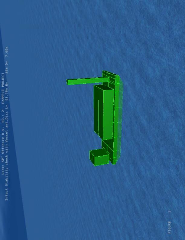
21 FIGURE 2 User: SPT Offshore b.v. NO.: 2 - EXAMPLE PROJECT Intact Stability check with Vessel amt_disc L= 91.70m B= 30m D= 7.60m
22 FIGURE 3 User: SPT Offshore b.v. NO.: 2 - EXAMPLE PROJECT Intact Stability check with Vessel amt_disc L= 91.70m B= 30m D= 7.60m
23 FIGURE 4 User: SPT Offshore b.v. NO.: 2 - EXAMPLE PROJECT Intact Stability check with Vessel amt_disc L= 91.70m B= 30m D= 7.60m
24 FIGURE 5 User: SPT Offshore b.v. NO.: 2 - EXAMPLE PROJECT Intact Stability check with Vessel amt_disc L= 91.70m B= 30m D= 7.60m
25 FIGURE 6 User: SPT Offshore b.v. NO.: 2 - EXAMPLE PROJECT BALLAST TANKS
26 FIGURE 7 WP6 WS6 User: SPT Offshore b.v. NO.: 2 - EXAMPLE PROJECT BALLAST TANKS WP5 WP4 WP3 CP5 CP4 CP3 CS5 CS4 CS3 WS5 WS4 WS3 WP2 CP2 CS2 WS2 P1 S1
27 FIGURE 8 WP6 48.9% WS6 48.4% User: SPT Offshore b.v. NO.: 2 - EXAMPLE PROJECT BALLAST PLAN VESSEL amt_disc L= 91.70m B= 30m D= 7.60m WP5 39.1% WP4 34.9% WP3 30.7% CP5 39.0% CP4 34.8% CP3 30.6% CS5 38.8% CS4 34.6% CS3 30.4% WS5 38.7% WS4 34.5% WS3 30.3% WP2 26.5% CP2 26.4% CS2 26.2% WS2 26.1% P1 26.2% S1 26.0%
28 Page 1 Licensee - Online Marine Engineering Rev Ser643 * *** MOSES *** * * November, 2010 * * User: SPT Offshore b.v. NO.: 2 - EXAMPLE PROJECT * * Barge Stillwater Longitudinal strength check * * * +++ L O N G I T U D I N A L S T R E N G T H R E S U L T S +++ ================================================================= Process is DEFAULT: Units Are Degrees, Meters, and M-Tons Unless Specified Allowable Stress = Allowable Deflection = 1.00 Mpa 1.00 MM Longitudinal Shear Bending B. Stress/ Deflection/ Location Force Moment Allowable Allowable
29 Page 2 Licensee - Online Marine Engineering Rev Ser643 * *** MOSES *** * * November, 2010 * * User: SPT Offshore b.v. NO.: 2 - EXAMPLE PROJECT * * Barge Longitudinal strength check - Hogging Wave * * * +++ L O N G I T U D I N A L S T R E N G T H R E S U L T S +++ ================================================================= Process is DEFAULT: Units Are Degrees, Meters, and M-Tons Unless Specified Static Wave Length = Steep = Crest Loc. = 45.8 Allowable Stress = Allowable Deflection = 1.00 Mpa 1.00 MM Longitudinal Shear Bending B. Stress/ Deflection/ Location Force Moment Allowable Allowable
30 Page 3 Licensee - Online Marine Engineering Rev Ser643 * *** MOSES *** * * November, 2010 * * User: SPT Offshore b.v. NO.: 2 - EXAMPLE PROJECT * * Barge Longitudinal strength check - Sagging Wave * * * +++ L O N G I T U D I N A L S T R E N G T H R E S U L T S +++ ================================================================= Process is DEFAULT: Units Are Degrees, Meters, and M-Tons Unless Specified Static Wave Length = Steep = Crest Loc. = 0.0 Allowable Stress = Allowable Deflection = 1.00 Mpa 1.00 MM Longitudinal Shear Bending B. Stress/ Deflection/ Location Force Moment Allowable Allowable
31 Page 4 Licensee - Online Marine Engineering Rev Ser643 * *** MOSES *** * * November, 2010 * * User: SPT Offshore b.v. NO.: 2 - EXAMPLE PROJECT * * BOLLARD PULL ANALYSIS - Wind 40 knots, Current 0.5 m/s and Hs = 5.0 m * * * +++ C U R R E N T E N V I R O N M E N T +++ ============================================= Process is DEFAULT: Units Are Degrees, Meters, and M-Tons Unless Specified Environment Name BOLLARD Observation Time = Time Increment = Time Offset = 0.0 Time Reinforce = S E A C O N D I T I O N Type = JONSWAP Hs = 5.00 Mean Period = 9.50 Gamma = 3.3 Dir = 0.0 S.Coe = 2 W I N D D A T A Hr. Wind Speed = 40.0 Knots, Direction = 0.0 Design Wind Based On ABS Rules Wind Height Variation Based on ABS Rules Wind is Static C U R R E N T D A T A DEPTH SPEED DIRECTION
32 Page 5 Licensee - Online Marine Engineering Rev Ser643 * *** MOSES *** * * November, 2010 * * User: SPT Offshore b.v. NO.: 2 - EXAMPLE PROJECT * * BOLLARD PULL ANALYSIS - Wind 40 knots, Current 0.5 m/s and Hs = 5.0 m * * * +++ B U O Y A N C Y A N D W E I G H T F O R M O D E L +++ ================================================================= Process is DEFAULT: Units Are Degrees, Meters, and M-Tons Unless Specified Results Are Reported In Body System Draft = 3.64 Roll Angle = 0.00 Pitch Angle = 0.20 Wet Radii Of Gyration About CG K-X = K-Y = K-Z = /-- Center of Gravity ---/ Sounding % Full Name Weight ---X Y Z Part AMT_DISC Contents --- CP CP CP CP CS CS CS CS P S WP WP WP WP WP WS WS WS WS WS Part CARGO LOAD_GRO Part CARGO LOAD_GRO Part CARGO LOAD_GRO Part LIGHTSHI LOAD_GRO Part MODEL ======== ======== ======= ======= ======= Total Buoyancy
33 Page 6 Licensee - Online Marine Engineering Rev Ser643 * *** MOSES *** * * November, 2010 * * User: SPT Offshore b.v. NO.: 2 - EXAMPLE PROJECT * * BOLLARD PULL ANALYSIS - Wind 40 knots, Current 0.5 m/s and Hs = 5.0 m * * * +++ F O R C E S A C T I N G O N M O D E L +++ =================================================== Process is DEFAULT: Units Are Degrees, Meters, and M-Tons Unless Specified Results Are Reported In Body System Type of Force X Y Z MX MY MZ Weight Contents Buoyancy Wind Drag ======= ======= ======= ======= ======= ======= Total
34 Page 7 Licensee - Online Marine Engineering Rev Ser643 * *** MOSES *** * * November, 2010 * * User: SPT Offshore b.v. NO.: 2 - EXAMPLE PROJECT * * DRAG ANALYSIS - Speed 7 kn * * * +++ C U R R E N T S Y S T E M C O N F I G U R A T I O N +++ =============================================================== Process is DEFAULT: Units Are Degrees, Meters, and M-Tons Unless Specified Location and Net Force at Body Origin Body X Y Z RX RY RZ MODEL Location N Force
35 Page 8 Licensee - Online Marine Engineering Rev Ser643 * *** MOSES *** * * November, 2010 * * User: SPT Offshore b.v. NO.: 2 - EXAMPLE PROJECT * * DRAG ANALYSIS - Speed 7 kn * * * +++ F O R C E S A C T I N G O N M O D E L +++ =================================================== Process is DEFAULT: Units Are Degrees, Meters, and M-Tons Unless Specified Results Are Reported In Body System Type of Force X Y Z MX MY MZ Weight Contents Buoyancy Drag ======= ======= ======= ======= ======= ======= Total
36 Page 9 Licensee - Online Marine Engineering Rev Ser643 * *** MOSES *** * * November, 2010 * * User: SPT Offshore b.v. NO.: 2 - EXAMPLE PROJECT * * Intact Stability check NDI Guidelines * * * +++ R I G H T I N G A R M R E S U L T S +++ =============================================== Process is DEFAULT: Units Are Degrees, Meters, and M-Tons Unless Specified Moment Scaled By , KG = 3.65, and Wind Speed = 40 Knots Initial: Roll = 0.00, Trim = 0.00 Deg. Arms About Axis Yawed 0.0 Deg From Vessel X /----- Condition -----/ /-- Min. Height --/ /--- Righting ---/ /--- Heeling ---/ Area Net Draft Roll Trim W Tight NW Tight Arm Area Arm Area Ratio Arm
37 Page 10 Licensee - Online Marine Engineering Rev Ser643 * *** MOSES *** * * November, 2010 * * User: SPT Offshore b.v. NO.: 2 - EXAMPLE PROJECT * * Intact Stability check NDI Guidelines * * * +++ S T A B I L I T Y S U M M A R Y +++ ========================================= The Following Intact Condition ============================== Draft = 3.80 M Roll = 0.00 Deg Pitch = 0.00 Deg VCG = 3.65 M Axis Angle = 0.00 Deg Wind Vel = Knots Passes All of The Stability Requirements: ========================================= Area Ratio >= 1.40 RA/HA Ratio >= 0.00 Dfld Equilibrium >= 0.00 M GM >= 0.00 M Arm Max Right. Arm >= 0.00 M*Deg Arm Dfld >= 0.00 M*Deg Arm 40 Degrees >= 0.00 M*Deg Area Under Righting Arm >= 0.00 M*Deg Static Heel w/o Wind <= Deg Static Heel Due to Wind <= Deg Range (Second Intercept) >= Deg 2nd - 1st Intercepts >= 0.00 Deg Dfld Angle - 1st Interc. >= 0.00 Deg Max Righting Arm >= 0.00 Deg Downflood Angle >= 0.00 Deg With The Stability Results: =========================== Area Ratio = Passes RA/HA Ratio = Passes Dfld Equilibrium = 0.00 M Passes GM = M Passes Arm Max Right Arm = M*Deg Passes Arm Dfld = M*Deg Passes Arm 40 Degrees = M*Deg Passes Area Under Righting Arm = M*Deg Passes Static Heel w/o Wind = 0.03 Deg Passes Static Heel Due to Wind = 0.16 Deg Passes Range = Deg Passes 2nd - 1st Intercepts = Deg Passes Dfld Angle - 1st Interc. = Deg Passes Max Right Arm = Deg Passes Downflood Angle = Deg Passes
38 Page 11 Licensee - Online Marine Engineering Rev Ser643 * *** MOSES *** * * November, 2010 * * User: SPT Offshore b.v. NO.: 2 - EXAMPLE PROJECT * * Intact Stability check IMO Guidelines * * * +++ R I G H T I N G A R M R E S U L T S +++ =============================================== Process is DEFAULT: Units Are Degrees, Meters, and M-Tons Unless Specified Moment Scaled By , KG = 3.65, and Wind Speed = 58 Knots Initial: Roll = 0.00, Trim = 0.00 Deg. Arms About Axis Yawed 0.0 Deg From Vessel X /----- Condition -----/ /-- Min. Height --/ /--- Righting ---/ /--- Heeling ---/ Area Net Draft Roll Trim W Tight NW Tight Arm Area Arm Area Ratio Arm
39 Page 12 Licensee - Online Marine Engineering Rev Ser643 * *** MOSES *** * * November, 2010 * * User: SPT Offshore b.v. NO.: 2 - EXAMPLE PROJECT * * Intact Stability check IMO Guidelines * * * +++ S T A B I L I T Y S U M M A R Y +++ ========================================= The Following Intact Condition ============================== Draft = 3.80 M Roll = 0.00 Deg Pitch = 0.00 Deg VCG = 3.65 M Axis Angle = 0.00 Deg Wind Vel = Knots Passes All of The Stability Requirements: ========================================= Area Ratio >= 0.00 RA/HA Ratio >= 0.00 Dfld Equilibrium >= 0.00 M GM >= 0.00 M Arm Max Right. Arm >= 4.58 M*Deg Arm Dfld >= 0.00 M*Deg Arm 40 Degrees >= 0.00 M*Deg Area Under Righting Arm >= 0.00 M*Deg Static Heel w/o Wind <= Deg Static Heel Due to Wind <= 7.22 Deg Range (Second Intercept) >= Deg 2nd - 1st Intercepts >= 0.00 Deg Dfld Angle - 1st Interc. >= 0.00 Deg Max Righting Arm >= 0.00 Deg Downflood Angle >= 0.00 Deg With The Stability Results: =========================== Area Ratio = Passes RA/HA Ratio = Passes Dfld Equilibrium = 0.00 M Passes GM = M Passes Arm Max Right Arm = M*Deg Passes Arm Dfld = M*Deg Passes Arm 40 Degrees = M*Deg Passes Area Under Righting Arm = M*Deg Passes Static Heel w/o Wind = 0.03 Deg Passes Static Heel Due to Wind = 0.34 Deg Passes Range = Deg Passes 2nd - 1st Intercepts = Deg Passes Dfld Angle - 1st Interc. = Deg Passes Max Right Arm = Deg Passes Downflood Angle = Deg Passes
40 User: SPT Offshore b.v. NO.: 2 - EXAMPLE PROJECT Barge Stillwater Longitudinal strength check Shear Moment Shear * 10** Moment * 10** Long Location FIGURE 9
41 User: SPT Offshore b.v. NO.: 2 - EXAMPLE PROJECT Barge Longitudinal strength check - Hogging Wave Shear Moment Shear * 10** Moment * 10** Long Location FIGURE 10
42 User: SPT Offshore b.v. NO.: 2 - EXAMPLE PROJECT Barge Longitudinal strength check - Sagging Wave Shear Moment Shear * 10** Moment * 10** Long Location FIGURE 11
43 User: SPT Offshore b.v. NO.: 2 - EXAMPLE PROJECT Intact Stability check NDI Guidelines Righting Arm Wind Arm Area Ratio Righting & Wind Heel Arms (Meters) Area Ratio Roll Angle (Deg) FIGURE 12
44 User: SPT Offshore b.v. NO.: 2 - EXAMPLE PROJECT Intact Stability check IMO Guidelines Righting Arm Wind Arm Area Ratio Righting & Wind Heel Arms (Meters) Area Ratio Roll Angle (Deg) FIGURE 13
45 Page 1 Licensee - Online Marine Engineering Rev Ser643 * *** MOSES *** * * November, 2010 * * User: SPT Offshore b.v. NO.: 2 - EXAMPLE PROJECT * * Damaged Stability check with Vessel amt_disc L= B= 30 D= 7.60 * * * +++ B U O Y A N C Y A N D W E I G H T F O R M O D E L +++ ================================================================= Process is DAMAGED: Units Are Degrees, Meters, and M-Tons Unless Specified Results Are Reported In Body System Draft = 3.78 Roll Angle = Pitch Angle = 0.12 Wet Radii Of Gyration About CG K-X = K-Y = K-Z = GMT = GML = /-- Center of Gravity ---/ Sounding % Full Name Weight ---X Y Z Part AMT_DISC Contents --- CP CP CP CP CS CS CS CS P S WP WP WP WP WP WS WS WS WS WS Part CARGO LOAD_GRO Part CARGO LOAD_GRO Part CARGO LOAD_GRO Part LIGHTSHI LOAD_GRO Part MODEL ======== ======== ======= ======= ======= Total Buoyancy
Hydrostatic and Stability IN A NUTSHELL. of Floating Structures. Compendium. Relevant to Questions in Exam. Robert Bronsart
 Hydrostatic and Stability of Floating Structures IN A NUTSHELL Compendium Relevant to Questions in Exam Robert Bronsart Version Date Comment 2.21 September 2015 minor corrections Author: Robert Bronsart
SPECIAL CONDITION. Water Load Conditions. SPECIAL CONDITION Water Load Conditions
 Doc. No. : SC-CVLA.051-01 Issue : 1d Date : 04-Aug-009 Page : 1 of 13 SUBJECT : CERTIFICATION SPECIFICATION : VLA.51 PRIMARY GROUP / PANEL : 03 (Structure) SECONDARY GROUPE / PANEL : -- NATURE : SCN VLA.51
Wuchang Shipbuilding Industry Co., Ltd. China Shipbuilding Industry Corporation
 Safety Assessments for Anchor Handling Conditions of Multi-purpose Platform Work Vessels Reporter:Yu Wang Wuchang Shipbuilding Industry Co., Ltd. China Shipbuilding Industry Corporation 2009.12.04 0 Outline
SHIP BUOYANCY AND STABILITY. Lecture 03 Ship initial stability
 SHIP BUOYANCY AND STABILITY Lecture 3 Ship initial stability 1 Literature J. Matusiak: Laivan kelluvuus ja vakavuus Biran A. B., Ship Hydrostatics and Stability, 23 J. Matusiak: Short Introduction to Ship
RULES PUBLICATION NO. 17/P ZONE STRENGTH ANALYSIS OF HULL STRUCTURE OF ROLL ON/ROLL OFF SHIP
 RULES PUBLICATION NO. 17/P ZONE STRENGTH ANALYSIS OF HULL STRUCTURE OF ROLL ON/ROLL OFF SHIP 1995 Publications P (Additional Rule Requirements), issued by Polski Rejestr Statków, complete or extend the
SAFEHULL-DYNAMIC LOADING APPROACH FOR VESSELS
 Guide for SafeHull- Dynamic Loading Approach for Vessels GUIDE FOR SAFEHULL-DYNAMIC LOADING APPROACH FOR VESSELS DECEMBER 2006 (Updated February 2014 see next page) American Bureau of Shipping Incorporated
RULES FOR CLASSIFICATION. Ships. Part 3 Hull Chapter 4 Loads. Edition January 2017 DNV GL AS
 RULES FOR CLASSIFICATION Ships Edition January 2017 Part 3 Hull Chapter 4 The content of this service document is the subject of intellectual property rights reserved by ("DNV GL"). The user accepts that
PAGE Ⅰ. INTENT 3 Ⅱ. PRINCIPAL PARTICULARS 4 Ⅳ. HOLD & TANK CAPACITY TABLE 6 Ⅴ. CURVES OF HEELING MOMENT, VOLUME AND KG 12
 1 GRAIN LOADING INDEX PAGE Ⅰ. INTENT 3 Ⅱ. PRINCIPAL PARTICULARS 4 Ⅲ. SYMBOLS 5 Ⅳ. HOLD & TANK CAPACITY TABLE 6 Ⅴ. CURVES OF HEELING MOMENT, VOLUME AND KG 12 Ⅵ. ALLOWABLE HEELING MOMENT EXPLANATION OF ALLOWABLE
Chapter IV. (Ship Hydro-Statics & Dynamics) Floatation & Stability
 Floatation & Stability") Chapter V (Ship Hydro-Statics & Dynamics) Floatation & Stability 4.1 mportant Hydro-Static Curves or Relations (see Fig. 4.11 at p44 & handout) Displacement Curves (displacement [molded, total] vs. draft,
Chapter V (Ship Hydro-Statics & Dynamics) Floatation & Stability 4.1 mportant Hydro-Static Curves or Relations (see Fig. 4.11 at p44 & handout) Displacement Curves (displacement [molded, total] vs. draft,
Department of Aerospace and Ocean Engineering Graduate Study Specialization in Ocean Engineering. Written Preliminary Examination Information
 Department of Aerospace and Ocean Engineering Graduate Study Specialization in Ocean Engineering Written Preliminary Examination Information Faculty: Professors W. Neu, O. Hughes, A. Brown, M. Allen Test
On an Advanced Shipboard Information and Decision-making System for Safe and Efficient Passage Planning
 International Journal on Marine Navigation and Safety of Sea Transportation Volume 2 Number 1 March 28 On an Advanced Shipboard Information and Decision-making System for Safe and Efficient Passage Planning
STABILITY AND TRIM OF MARINE VESSELS. Massachusetts Institute of Technology, Subject 2.017
 STABILITY AND TRIM OF MARINE VESSELS Concept of Mass Center for a Rigid Body Centroid the point about which moments due to gravity are zero: 6 g m i (x g x i )= 0 Æ x = 6m i x i / 6m i = 6m i x i / M g
RISK EVALUATION IN FLOATING OFFSHORE STRUCTURES. José M. Vasconcellos, COPPE/UFRJ, Nara Guimarães, COPPE/UFRJ,
 10 th International Conference 53 RISK EVALUATION IN FLOATING OFFSHORE STRUCTURES José M. Vasconcellos, COPPE/UFRJ, jmarcio@ufrj.br Nara Guimarães, COPPE/UFRJ, nara@peno.coppe.ufrj.br ABSTRACT During a
Hydrostatics and Stability Dr. Hari V Warrior Department of Ocean Engineering and Naval Architecture Indian Institute of Technology, Kharagpur
 Hydrostatics and Stability Dr. Hari V Warrior Department of Ocean Engineering and Naval Architecture Indian Institute of Technology, Kharagpur Module No. # 01 Lecture No. # 09 Free Surface Effect In the
SHIP BUOYANCY AND STABILITY
 SHIP BUOYANCY AND STABILITY Lecture 04 Ship stability-z curve 09/11/2017 Ship Buoyancy and Stability 1 Literature J. Matusiak: Laivan kelluvuus ja vakavuus Biran A. B., Ship Hydrostatics and Stability,
Formation Design Systems' Maxsurf Stability Tank Table Generator: Verification and Validation Study
 Formation Design Systems' Maxsurf Stability Tank Table Generator: Verification and Validation Study Edward Dawson Maritime Division Defence Science and Technology Organisation DSTO-TR-2968 ABSTRACT A verification
CARGO STOWAGE AND SECURING
 Resolutions from the 17th Session of the Assembly of IMO, November 1991, as amended CODE OF SAFE PRACTICE FOR CARGO STOWAGE AND SECURING CARGO STOWAGE AND SECURING ANNEX 13. Til bruk i maritime fagskoler
Final Exam TTK4190 Guidance and Control
 Trondheim Department of engineering Cybernetics Contact person: Professor Thor I. Fossen Phone: 73 59 43 61 Cell: 91 89 73 61 Email: tif@itk.ntnu.no Final Exam TTK4190 Guidance and Control Friday May 15,
Longitudinal strength standard
 (1989) (Rev. 1 199) (Rev. Nov. 001) Longitudinal strength standard.1 Application This requirement applies only to steel ships of length 90 m and greater in unrestricted service. For ships having one or
RULES FOR CLASSIFICATION Inland navigation vessels. Part 3 Structures, equipment Chapter 2 Design load principles. Edition December 2015 DNV GL AS
 RULES FOR CLASSIFICATION Inland navigation vessels Edition December 2015 Part 3 Structures, equipment Chapter 2 s The content of this service document is the subject of intellectual property rights reserved
RULES FOR THE CONSTRUCTION AND CLASSIFICATION OF SHIPS IDENTIFIED BY THEIR MISSIONS DREDGERS AND MUD BARGES CHAPTERS CHAPTERS SCOPE
 PARTE II RULES FOR THE CONSTRUCTION AND CLASSIFICATION OF SHIPS IDENTIFIED BY THEIR MISSIONS TÍTULO 43 DREDGERS AND MUD BARGES SECTION 2 STRUCTURE CHAPTERS SECTION 2 STRUCTURE CHAPTERS A B C SCOPE DOCUMENTS,
Requirements for Computational Methods to be sed for the IMO Second Generation Intact Stability Criteria
 Proceedings of the 1 th International Conference on the Stability of Ships and Ocean Vehicles, 14-19 June 15, Glasgow, UK Requirements for Computational Methods to be sed for the IMO Second Generation
ITTC Recommended Procedures and Guidelines
 Page 1 of 9 CONTENTS Model Test Experiments... 2 1. PURPOSE OF PROCEDURE... 2 2. PARAMETERS... 2 2.1 Model Parameters... 3 2.2 Environmental Parameters... 3 2.3 Operation of Thrusters... 3 2.3.1 Thruster-Current
Aalto University School of Engineering
 Aalto University School of Engineering Kul-24.4140 Ship Dynamics (P) Lecture 9 Loads Where is this lecture on the course? Design Framework Lecture 5: Equations of Motion Environment Lecture 6: Strip Theory
SHIP BUOYANCY AND STABILITY. Lecture 02 Ship equilibrium and introduction to ship hydrostatics
 SHIP BUOYANCY AND STABILITY Lecture 02 Ship equilibrium and introduction to ship hydrostatics 1 Literature J. Matusiak: Laivan kelluvuus ja vakavuus Biran A. B., Ship Hydrostatics and Stability, 2003 J.
Initial Stress Calculations
 Initial Stress Calculations The following are the initial hand stress calculations conducted during the early stages of the design process. Therefore, some of the material properties as well as dimensions
SLAMMING INDUCED DYNAMIC RESPONSE OF A FLOATING STRUCTURE
 Journal of Marine Science and Technology, Vol., No., pp. 1-9 (1) 1 SLAMMING INDUCED DYNAMIC RESPONSE OF A FLOATING STRUCTURE Mohammad Ali Lotfollahi-Yaghin 1, Mehdi Rastgar, and Hamid Ahmadi 1 Key words:
RULES FOR CLASSIFICATION Ships. Part 3 Hull Chapter 6 Hull local scantling. Edition October 2015 DNV GL AS
 RULES FOR CLASSIFICATION Ships Edition October 2015 Part 3 Hull Chapter 6 The content of this service document is the subject of intellectual property rights reserved by ("DNV GL"). The user accepts that
Welcome to the Ship Resistance Predictor! The total calm water resistance is given by:
 Welcome to the Ship Resistance Predictor! What does this Excel Sheet do? This Excel sheet helps you calculate the Total Calm Water Resistance for a Ship at a given forward speed It also calculates from
RULES FOR CLASSIFICATION. Ships. Part 3 Hull Chapter 6 Hull local scantling. Edition January 2017 DNV GL AS
 RULES FOR CLASSIFICATION Ships Edition January 2017 Part 3 Hull Chapter 6 The content of this service document is the subject of intellectual property rights reserved by ("DNV GL"). The user accepts that
API 4F, 4th Edition, Purchasing Guideline
 The following information should be provided by the purchaser when making an inquiry or placing an order: a) Reference to this standard; b) Reference to any requirement for third party certification, name
Sabah Shawkat Cabinet of Structural Engineering Walls carrying vertical loads should be designed as columns. Basically walls are designed in
 Sabah Shawkat Cabinet of Structural Engineering 17 3.6 Shear walls Walls carrying vertical loads should be designed as columns. Basically walls are designed in the same manner as columns, but there are
ITTC Recommended Procedures Testing and Extrapolation Methods Resistance Resistance Test
 -0- Page 1 of 11 CONTENTS 1. PURPOSE OF PROCEDURE. PARAMETERS.1 Data Reduction Equations. Definition of ariables 3. DESCRIPTION OF PROCEDURE 3.1 Model and Installation 3.1.1 Model 3.1. Test condition 3.1.3
MEMBRANE TANK LNG VESSELS
 Guide for Building and Classing Membrane Tank LNG Vessels GUIDE FOR BUILDING AND CLASSING MEMBRANE TANK LNG VESSELS (HULL STRUCTURAL DESIGN AND ANALYSIS BASED ON THE ABS SAFEHULL APPROACH) OCTOBER 2002
CAPACITY ESTIMATES AND GENERAL ARRANGEMENT
 CAPACITY ESTIMATES AND GENERAL ARRANGEMENT This will verify that sufficient space is available for the amount of cargo to be carried. For capacity ships, it is a primary factor and may be a starting point
Seakeeping characteristics of intact and damaged ship in the Adriatic Sea
 Towards Green Marine Technology and Transport Guedes Soares, Dejhalla & Pavleti (Eds) 2015 Taylor & Francis Group, London, ISBN 978-1-138-02887-6 Seakeeping characteristics of intact and damaged ship in
Conversion of an Oil Tanker into FPSO. Strength Analysis using ABS Rules
 National Technical University of Athens School of Naval Architecture & Marine Engineering Division of Marine Structures Conversion of an Oil Tanker into FPSO. Strength Analysis using ABS Rules Diploma
Safetrans Safe design and operation of marine transports
 Safetrans Safe design and operation of marine transports CONTENTS General Voyage Motion Climate Monte Carlo Simulations Calculation of Ship Motions Weather Databases User Group References 2 SAFETRANS Safetrans
RULES PUBLICATION NO. 18/P ZONE STRENGTH ANALYSIS OF BULK CARRIER HULL STRUCTURE
 RULES PUBLICATION NO. 18/P ZONE STRENGTH ANALYSIS OF BULK CARRIER HULL STRUCTURE 1995 Publications P (Additional Rule Requirements), issued by Polski Rejestr Statków, complete or extend the Rules and are
Final Exam Ship Structures Page 1 MEMORIAL UNIVERSITY OF NEWFOUNDLAND. Engineering Ship Structures
 Final Exam - 53 - Ship Structures - 16 Page 1 MEMORIA UNIVERSITY OF NEWFOUNDAND Faculty of Engineering and Applied Science Engineering 53 - Ship Structures FINA EXAMINATION SONS Date: Wednesday April 13,
SEAKEEPING AND MANEUVERING Prof. Dr. S. Beji 2
 SEAKEEPING AND MANEUVERING Prof. Dr. S. Beji 2 Ship Motions Ship motions in a seaway are very complicated but can be broken down into 6-degrees of freedom motions relative to 3 mutually perpendicular axes
Motions and Resistance of a Ship in Regular Following Waves
 Reprinted: 01-11-2000 Revised: 03-10-2007 Website: www.shipmotions.nl Report 440, September 1976, Delft University of Technology, Ship Hydromechanics Laboratory, Mekelweg 2, 2628 CD Delft, The Netherlands.
SCALE MODEL TESTS OF A FISHING VESSEL IN ROLL MOTION PARAMETRIC RESONANCE
 N. Perez Síntesis Tecnológica. V.3 Nº 1 (26) 33-37 SCALE MODEL TESTS OF A FISHING VESSEL IN ROLL MOTION PARAMETRIC RESONANCE NELSON A. PEREZ M. Instituto de Ciencias Navales y Marítimas, M.Sc, nperez@uach.cl,
Machinery Requirements for Polar Class Ships
 (August 2006) (Rev.1 Jan 2007) (Corr.1 Oct 2007) Machinery Requirements for Polar Class Ships.1 Application * The contents of this Chapter apply to main propulsion, steering gear, emergency and essential
HEAVE DAMPING EFFECTS DUE TO CIRCULAR PLATES ATTACHED AT KEEL TO SPAR HULL
 HEAVE DAMPING EFFECTS DUE TO CIRCULAR PLATES ATTACHED AT KEEL TO SPAR HULL P.Uma 1 1 M.TECH Civil Engineering Dadi Institute of Engineering and Technology College Abstract Single point Anchor Reservoir
RULES FOR CLASSIFICATION. Ships. Part 3 Hull Chapter 10 Special requirements. Edition January 2017 DNV GL AS
 RULES FOR CLASSIFICATION Ships Edition January 2017 Part 3 Hull Chapter 10 The content of this service document is the subject of intellectual property rights reserved by ("DNV GL"). The user accepts that
STEEPEST DESCENT METHOD. RESOLVING AN OLD PROBLEM
 1 th International Conference 87 STEEPEST DESCENT METHOD. RESOLVING AN OLD PROBLEM J. Andrew Breuer, ABS, ABreuer@eagle.org Karl-Gustav Sjölund, SeaSafe Marine Software AB, mail@seasafe.se ABSTRACT New
Numerical Study of the Roll Decay of Intact and Damaged Ships by Q. Gao and D. Vassalos
 Session 7 Stability of Damaged Ships Numerical Simulation of Progressive Flooding and Capsize Numerical Study of the Roll Decay of Intact and Damaged Ships by Q. Gao and D. Vassalos Qiuxin Gao and Dracos
Optimal Design of FPSO Vessels
 November 2, 201 Optimal Design of FPSO Vessels Ezebuchi Akandu PhD, MTech, BTech, COREN, RINA, MNSE Department of Marine Engineering, Rivers State University, Port Harcourt, Nigeria akandu.ezebuchi@ust.edu.ng
IMO REVISION OF THE INTACT STABILITY CODE. Report of the Working Group on Intact Stability at SLF 48 (part 2)
") INTERNATIONAL MARITIME ORGANIZATION E IMO SUB-COMMITTEE ON STABILITY AND LOAD LINES AND ON FISHING VESSELS SAFETY 49th session Agenda item 5 SLF 49/5/1 23 March 26 Original: ENGLISH REVISION OF THE INTACT
INTERNATIONAL MARITIME ORGANIZATION E IMO SUB-COMMITTEE ON STABILITY AND LOAD LINES AND ON FISHING VESSELS SAFETY 49th session Agenda item 5 SLF 49/5/1 23 March 26 Original: ENGLISH REVISION OF THE INTACT
DYNAMIC LOADING APPROACH FOR FLOATING PRODUCTION, STORAGE AND OFFLOADING (FPSO) INSTALLATIONS
 INSTALLATIONS") Guide for Dynamic Loading Approach for Floating Production, Storage and Offloading (FPSO) Installations GUIDE FOR DYNAMIC LOADING APPROACH FOR FLOATING PRODUCTION, STORAGE AND OFFLOADING (FPSO) INSTALLATIONS
Guide for Dynamic Loading Approach for Floating Production, Storage and Offloading (FPSO) Installations GUIDE FOR DYNAMIC LOADING APPROACH FOR FLOATING PRODUCTION, STORAGE AND OFFLOADING (FPSO) INSTALLATIONS
Sailing Performance and Maneuverability of a Traditional Ryukyuan Tribute Ship
 sia Navigation Conference 009 ailing Performance and Maneuverability of a Traditional Ryukyuan Tribute hip by Yutaka MUYM (Kanazawa Institute of Technology) Hikaru YGI (Tokai University ) Yutaka TERO (Tokai
Capstan Design (Capstan Power) for Berthing
 for Berthing") What does this Excel Sheet do? Capstan Design (Capstan Power) for Berthing This Excel sheet helps the user obtain the required Capstan Line Pull and Capstan Power for berthing operations The Capstan can
What does this Excel Sheet do? Capstan Design (Capstan Power) for Berthing This Excel sheet helps the user obtain the required Capstan Line Pull and Capstan Power for berthing operations The Capstan can
Ice Class Regulations and the Application Thereof
 1 (65) Date of issue: 14 Nov. 2017 Entry into force: 1 Dec. 2017 Validity: indefinitely Legal basis: Act on the Ice Classes of Ships and Icebreaker Assistance (1121/2005), section 4.1 Implemented EU legislation:
ROLL MOTION OF A RORO-SHIP IN IRREGULAR FOLLOWING WAVES
 38 Journal of Marine Science and Technology, Vol. 9, o. 1, pp. 38-44 (2001) ROLL MOTIO OF A RORO-SHIP I IRREGULAR FOLLOWIG WAVES Jianbo Hua* and Wei-Hui Wang** Keywords: roll motion, parametric excitation,
D y E y = E y. Legend:
 MODAL APPENDIX 1 ASME BPVC.XII-2017 Figure 1-1.4(a)-2 Maximum Range for Tensile Strength Properties, for Categories 406, 407, and 412 Class 3 Tanks Where Yield Strength Is the Determining Criterion for
Dynamics of Machinery
 Dynamics of Machinery Two Mark Questions & Answers Varun B Page 1 Force Analysis 1. Define inertia force. Inertia force is an imaginary force, which when acts upon a rigid body, brings it to an equilibrium
ADDED RESISTANCE IN WAVES OF INTACT AND DAMAGED SHIP IN THE ADRIATIC SEA
 Brodogradnja/Shipbilding Volume 66 Number, 15 Ivana Martić Nastia Degiuli ISSN 7-15X eissn 1845-5859 ADDED RESISTANCE IN WAVES OF INTACT AND DAMAGED SHIP IN THE ADRIATIC SEA Summary UDC 69.5.15.4(6.3)
Effect of Tethers Tension Force in the Behavior of a Tension Leg Platform Subjected to Hydrodynamic Force Amr R. El-Gamal, Ashraf Essa, Ayman Ismail
 Vol:7, No:1, 13 Effect of Tethers Tension Force in the Behavior of a Tension Leg Platform Subjected to Hydrodynamic Force Amr R. El-Gamal, Ashraf Essa, Ayman Ismail International Science Index, Bioengineering
Fluid Mechanics Prof. S. K. Som Department of Mechanical Engineering Indian Institute of Technology, Kharagpur. Lecture - 8 Fluid Statics Part V
 Fluid Mechanics Prof. S. K. Som Department of Mechanical Engineering Indian Institute of Technology, Kharagpur Lecture - 8 Fluid Statics Part V Good morning, I welcome you all to the session of fluid mechanics.
E & P SERV/US-SUB/ISBM INSTALLATION OF SUBSEA FACILITIES AREA: INDEX OF REVISIONS
 E&P-SERV US-SUB/ISBM TECHNICAL SPECIFICATION Nº: I-ET-3000.00-6600-941-PMU-002 1 de 48 PROJECT: INSTALLATION OF SUBSEA FACILITIES AREA: SUBSEA FACILITIES INDEX OF REVISIONS REV DESCRIPTION AND/OR AFFECTED
S19 S19. (1997) (Rev ) (Rev. 2 Feb. 1998) (Rev.3 Jun. 1998) (Rev.4 Sept. 2000) (Rev.5 July 2004) S Application and definitions
 (Rev ) (Rev. 2 Feb. 1998) (Rev.3 Jun. 1998) (Rev.4 Sept. 2000) (Rev.5 July 2004) S Application and definitions") (1997) (Rev. 1 1997) (Rev. Feb. 1998) (Rev.3 Jun. 1998) (Rev.4 Sept. 000) (Rev.5 July 004) Evaluation of Scantlings of the Transverse Watertight Corrugated Bulkhead between Cargo Holds Nos. 1 and, with
(1997) (Rev. 1 1997) (Rev. Feb. 1998) (Rev.3 Jun. 1998) (Rev.4 Sept. 000) (Rev.5 July 004) Evaluation of Scantlings of the Transverse Watertight Corrugated Bulkhead between Cargo Holds Nos. 1 and, with
 Balcony balustrades using the SG12 laminated glass system: PAGE 1 (SG12FF010717) Structural Calculations for SG12 System balustrades using 21.5mm laminated toughened glass without the need for a handrail
Comparison of Present Wave Induced Load Criteria with Loads Induced by an Abnormal Wave
 Rogue Waves 2004 1 Comparison of Present Wave Induced Load Criteria with Loads Induced by an Abnormal Wave C. Guedes Soares, N. Fonseca, R. Pascoal Unit of Marine Engineering and Technology, Technical
Corrigenda 1 to 01 January 2017 version
 Common Structural Rules for Bulk Carriers and Oil Tankers Corrigenda 1 to 01 January 2017 version Note: This Corrigenda enters into force on 1 st July 2017. Copyright in these Common Structural Rules is
Workshop 8. Lateral Buckling
 Workshop 8 Lateral Buckling cross section A transversely loaded member that is bent about its major axis may buckle sideways if its compression flange is not laterally supported. The reason buckling occurs
AB Engineering Manual
 AB Engineering Manual Allan Block Retaining Walls Excerptfrom theabengineeringmanualforretainingwals CHAPTER FIVE Seismic Analysis Introduction In seismic design we take a dynamic force and analyze it
The use of a floating quay for container terminals. 1. Introduction
 The use of a floating quay for container terminals. M. van der Wel M.vanderWel@student.tudelft.nl Ir. J.G. de Gijt J.G.deGijt@tudelft.nl Public Works Rotterdam/TU Delft Ir. D. Dudok van Heel D.DudokvanHeel@gw.rotterdam.nl
Static Forces on Surfaces-Buoyancy. Fluid Mechanics. The equilibrium of a body may be: Stable. Unstable. Neutral (could be considered stable)
") Equilibrium of Floating Bodies: To be the floating body in equilibrium, two conditions must be satisfied: The buoyant Force (F b ) must equal the weight of the floating body (W). F b and W must act in
Equilibrium of Floating Bodies: To be the floating body in equilibrium, two conditions must be satisfied: The buoyant Force (F b ) must equal the weight of the floating body (W). F b and W must act in
SPRINGING ASSESSMENT FOR CONTAINER CARRIERS
 Guidance Notes on Springing Assessment for Container Carriers GUIDANCE NOTES ON SPRINGING ASSESSMENT FOR CONTAINER CARRIERS FEBRUARY 2014 American Bureau of Shipping Incorporated by Act of Legislature
Additional Design Procedures
 ShipRight................................................ Design and construction Additional Design Procedures Procedure for Analysis of Pump Tower and Pump Tower Base September 008 ABCD Lloyd s Register
DESIGN AND DETAILING OF COUNTERFORT RETAINING WALL
 DESIGN AND DETAILING OF COUNTERFORT RETAINING WALL When the height of the retaining wall exceeds about 6 m, the thickness of the stem and heel slab works out to be sufficiently large and the design becomes
Safe Struck Ship (3S):Software Package for Structural analysis of collision between ships
:Software Package for Structural analysis of collision between ships") Port Said Engineering Research Journal Faculty of Engineering - Port Said University Volume 16 No. 2 pp.: 68:79 Safe Struck Ship (3S):Software Package for Structural analysis of collision between ships
Port Said Engineering Research Journal Faculty of Engineering - Port Said University Volume 16 No. 2 pp.: 68:79 Safe Struck Ship (3S):Software Package for Structural analysis of collision between ships
Development of formulas allowing to predict hydrodynamic responses of inland vessels operated within the range of navigation 0.6 Hs 2.
 Gian Carlo Matheus Torres 6 th EMship cycle: October 2015 February 2017 Master Thesis Development of formulas allowing to predict hydrodynamic responses of inland vessels operated within the range of navigation
Stability of free-floating ship
 Stability of free-floating ship Part II Maciej Paw³owski Gdañsk University of Technology ABSTRACT This is the second part of the paper published in Polish Maritime Research no. 2/2005, dealing with the
SLAMMING LOADS AND STRENGTH ASSESSMENT FOR VESSELS
 Guide for Slamming Loads and Strength Assessment for Vessels GUIDE FOR SLAMMING LOADS AND STRENGTH ASSESSMENT FOR VESSELS MARCH 2011 (Updated February 2016 see next page) American Bureau of Shipping Incorporated
Shear force and bending moment of beams 2.1 Beams 2.2 Classification of beams 1. Cantilever Beam Built-in encastre' Cantilever
 CHAPTER TWO Shear force and bending moment of beams 2.1 Beams A beam is a structural member resting on supports to carry vertical loads. Beams are generally placed horizontally; the amount and extent of
Ship structure dynamic analysis - effects of made assumptions on computation results
 Ship structure dynamic analysis - effects of made assumptions on computation results Lech Murawski Centrum Techniki Okrętowej S. A. (Ship Design and Research Centre) ABSTRACT The paper presents identification
TABLE OF CONTANINET 1. Design criteria. 2. Lateral loads. 3. 3D finite element model (SAP2000, Ver.16). 4. Design of vertical elements (CSI, Ver.9).
. 4. Design of vertical elements (CSI, Ver.9).") TABLE OF CONTANINET 1. Design criteria. 2. Lateral loads. 2-1. Wind loads calculation 2-2. Seismic loads 3. 3D finite element model (SAP2000, Ver.16). 4. Design of vertical elements (CSI, Ver.9). 4-1.
TABLE OF CONTANINET 1. Design criteria. 2. Lateral loads. 2-1. Wind loads calculation 2-2. Seismic loads 3. 3D finite element model (SAP2000, Ver.16). 4. Design of vertical elements (CSI, Ver.9). 4-1.
Selection Calculations For Linear & Rotary Actuators
 H-8 For Electric Linear Slides and Electric Cylinders First determine your series, then select your product. Select the actuator that you will use based on the following flow charts: Selection Procedure
The basic dynamic load rating C is a statistical number and it is based on 90% of the bearings surviving 50 km of travel carrying the full load.
 Technical data Load Rating & Life Under normal conditions, the linear rail system can be damaged by metal fatigue as the result of repeated stress. The repeated stress causes flaking of the raceways and
A numerical DP MODULE to help design and operation for projects including DP components
 DYNAMIC POSITIONING CONFERENCE November 15-16, 25 Control Systems I A numerical DP MODULE to help design and operation for projects including DP components C. Le Cunff PRINCIPIA (La Ciotat, France) Return
99/104 Large-Deflection Coupled Torsion/Bending
 99/104 Large-Deflection Coupled Torsion/Bending 1. Introduction Recent work of Reismann 1 considers numerical analysis of the large-deflection due to coupled torsion/bending of a weightless cantilever.
An accurate model for seaworthy container vessel stowage planning with ballast tanks
 Downloaded from orbit.dtu.dk on: Jul 23, 28 An accurate model for seaworthy container vessel stowage planning with ballast tanks Pacino, Dario; Delgado-Ortegon, Alberto; Jensen, Rune Møller; Bebbington,
Earthquake Loads According to IBC IBC Safety Concept
 Earthquake Loads According to IBC 2003 The process of determining earthquake loads according to IBC 2003 Spectral Design Method can be broken down into the following basic steps: Determination of the maimum
ASSESSMENT OF STRESS CONCENTRATIONS IN LARGE CONTAINER SHIPS USING BEAM HYDROELASTIC MODEL
 ASSESSMENT OF STRESS CONCENTRATIONS IN LARGE CONTAINER SHIPS USING BEAM HYDROELASTIC MODEL Ivo Senjanović, Nikola Vladimir Faculty of Mechanical Engineering and Naval Architecture, University of Zagreb,
A Preliminary Analysis on the Statistics of about One-Year Air Gap Measurement for a Semi-submersible in South China Sea
 Proceedings of the Twenty-sixth (2016) International Ocean and Polar Engineering Conference Rhodes, Greece, June 26-July 1, 2016 Copyright 2016 by the International Society of Offshore and Polar Engineers
Coastal and Hydraulics Laboratory
 ERDC/CHL TR-11-5 Vertical Ship Motion Study for Savannah, GA Entrance Channel Michael J. Briggs and William G. Henderson September 2011 Coastal and Hydraulics Laboratory Approved for public release; distribution
Proceedings of the ASME th International Conference on Ocean, Offshore and Arctic Engineering OMAE2013 June 9-14, 2013, Nantes, France
 Proceedings of the ASME 2011 32th International Conference on Ocean, Offshore and Arctic Engineering OMAE2013 June 9-14, 2013, Nantes, France OMAE2013-10124 APPLYING STRIP THEORY BASED LINEAR SEAKEEPING
Evaluation of Scantlings of Corrugated Transverse Watertight Bulkheads in Non-CSR Bulk Carriers Considering Hold Flooding
 (1997) (Rev.1 1997) (Rev.1.1 Mar 1998 /Corr.1) (Rev. Sept 000) (Rev.3 eb 001) (Rev.4 Nov 001) (Rev.5 July 003) (Rev.6 July 004) (Rev.7 eb 006) (Corr.1 Oct 009) (Rev.8 May 010) (Rev.9 Apr 014) Evaluation
H2 Stability of a Floating Body
 H2 Stability of a Floating Body TecQuipment Ltd 2015 Do not reproduce or transmit this document in any form or by any means, electronic or mechanical, including photocopy, recording or any information
AN EXPERIMENTAL STUDY OF HULL GIRDER LOADS ON AN INTACT AND DAMAGED NAVAL SHIP
 AN EXPERIMENTAL STUDY OF HULL GIRDER LOADS ON AN INTACT AND DAMAGED NAVAL SHIP E.Begovic 1, A.H. Day 2, A. Incecik 2 1 - Department of Industrial Engineering, University of Naples Federico II, Via Claudio
Rules for Classification and Construction Analysis Techniques
 V Rules for Classification and Construction Analysis Techniques 1 Hull Structural Design Analyses 2 Guidelines for Fatigue Strength Analyses of Ship Structures Edition 2004 The following Guidelines come
CFD Based Hull Hydrodynamic Forces for Simulation of Ship Manoeuvres
 International Journal on Marine avigation and Safety of Sea Transportation Volume 3 umber 1 March 9 Based Hull Hydrodynamic Forces for Simulation of Ship Manoeuvres T. Tabaczek, T. Gornicz & J. Kulczyk
Structural Calculations for Juliet balconies using BALCONY 2 System (Aerofoil) handrail. Our ref: JULB2NB Date of issue: March 2017
 handrail. Our ref: JULB2NB Date of issue: March 2017") Juliet balconies using BALCONY 2 System (Aerofoil) handrail PAGE 1 (ref: JULB2NB280317) Structural Calculations for Juliet balconies using BALCONY 2 System (Aerofoil) handrail Our ref: JULB2NB280317 Date
Juliet balconies using BALCONY 2 System (Aerofoil) handrail PAGE 1 (ref: JULB2NB280317) Structural Calculations for Juliet balconies using BALCONY 2 System (Aerofoil) handrail Our ref: JULB2NB280317 Date
ShipRight Design and Construction
 ShipRight Design and Construction Structural Design Assessment Global Design Loads of Container Ships and Other Ships Prone to Whipping and Springing January 2018 Working together for a safer world Document
Structural Rules for Container Ships
 Structural Rules for Container Ships NR 625 Consolidated edition for documentation only July 2016 with amendments November 2017 This document is an electronic consolidated edition of the Structural Rules
UNIT-I (FORCE ANALYSIS)
") DHANALAKSHMI SRINIVASAN INSTITUTE OF RESEACH AND TECHNOLOGY DEPARTMENT OF MECHANICAL ENGINEERING QUESTION BANK ME2302 DYNAMICS OF MACHINERY III YEAR/ V SEMESTER UNIT-I (FORCE ANALYSIS) PART-A (2 marks)
DHANALAKSHMI SRINIVASAN INSTITUTE OF RESEACH AND TECHNOLOGY DEPARTMENT OF MECHANICAL ENGINEERING QUESTION BANK ME2302 DYNAMICS OF MACHINERY III YEAR/ V SEMESTER UNIT-I (FORCE ANALYSIS) PART-A (2 marks)
Study on Strut Effect on Turning Characteristics of LNG Carrier
 Study on Strut Effect on Turning Characteristics of LNG Carrier Mohd Amirul Hamdi Bin Mohd Alwi, a Jaswar Koto, a, b,* and Zulkarnain, b a) Department of Aeronautics, Automotive and Ocean Engineering,Mechanical
Mechanics of Materials Primer
 Mechanics of Materials rimer Notation: A = area (net = with holes, bearing = in contact, etc...) b = total width of material at a horizontal section d = diameter of a hole D = symbol for diameter E = modulus