SHIP BUOYANCY AND STABILITY. Lecture 03 Ship initial stability
|
|
|
- Roxanne Lora Turner
- 6 years ago
- Views:
Transcription
1 SHIP BUOYANCY AND STABILITY Lecture 3 Ship initial stability 1
2 Literature J. Matusiak: Laivan kelluvuus ja vakavuus Biran A. B., Ship Hydrostatics and Stability, 23 J. Matusiak: Short Introduction to Ship Theory (Part 1) Rawson, K. J J. Basic Ship Theory Volume Buoyancy and Stability of a Ship, Finnish text book A Ship Stability book in English. Shorten version of the Finnish textbook, in English Check the library Available on KNOVEL as e-book 2
3 Center of Buoyancy curve Center of Flotation Wedge method Small angle assumption BEFORE THIS LECTURE Metacenter and metacentric radius Now, you should be able to: Describe qualitatively how the center of buoyancy varies, according to draft change or heeling angle Describe the ship inclination axes, defined by the center of flotation Use the wedge method results Describe the main outcomes of the small angle assumption Define the metacenter and its relation with the curve of the center of buoyancy 3
 Second generation of intact stability criteria Ship Damage Stability Stability special topics")
4 Introduction Preparation for the laboratory test Dynamic stability Following lecturers Ship equilibrium and introduction to hydrostatics Ship initial Stability Metacentric height GM Longitudinal metacentric height GM L The stability curve (GZ curve) Second generation of intact stability criteria Ship Damage Stability Stability special topics 4

5 Stability of the equilibrium Stability (in general): The property, quality, or characteristic of a body, which cause it, when its equilibrium is disturbed, to develop forces or moments acting to restore its original condition HOW DO WE ASSESS THE STABILITY OF A SHIP? 5

6 Definitions of Ship Stability Different approaches in investigating ship stability for different conditions INITIAL STABILITY (small angles): It represents the mechanical stability of the equilibrium to small perturbations. It is based on the Euler theorem thesis and assessed by analyzing the metacentric high; 6

. FINITE/LARGE ANGLES Static stability taking into account constant external moments.")
7 Definitions of Ship Stability Different approaches in investigating ship stability for different conditions STABILITY AT FINITE ANGLES : It represents the tendency of a ship to return to the initial equilibrium condition after a significant perturbation, and not capsize. It is a way to assess the stability of the ship subjected to external actions. The small angles assumptions are not valid anymore. It is asses by analyzing the GZ curves (righting arm). FINITE/LARGE ANGLES Static stability taking into account constant external moments. Dynamic stability (defined by the area under GZ curve) taking into account dynamic moments 7


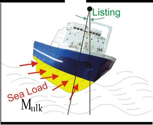
8 = B N sin Ship stability M ulk + M st = M st = GZ = h M st 8
9 Ship stability-in general Ship is stable, to small or large external actions, if the moment arising M st is of restoring type. Restoring means the moment works to bring the ship in the initial condition, against the external moment. The lever of this moment is the distance between the weight line and the buoyancy line. It varies according to the angle of inclination, i.e. at each equilibrium floating position related to the heel angle. Z G B 2 B B 4 B 16 K 9

10 CENTER of BUOYANCY curve 1

11 GZ curve 11
12 SHIP INITIAL STABILITY: SMALL PERTURBATION SMALL ANGLES 12

13 Initial Stability of a 6DoF Body DEFINITION: A generic body with 6 degree of freedom is stable in any direction if those conditions are satisfied: F x x x, F y y y, F z z z, M x, M y, M z Example with curvilinear abscissa The system is stable F s s s s s In the stability calculation the external actions causing the perturbations do not figure. 13
14 VERTICAL STABILITY OF A SHIP F x x x, F y y y, F z z z, M x, M y, M z 14
15 Ship stability in the vertical direction T z z, z' W G T W + W G y' T B y K B' T y T K a) b) c) z, z' W G y' B' y K W a: ship in equilibrium under weight and buoyancy force b: ship perturbed with a weight increment W that leads to a draft increment, in order to generate an increment of buoyancy equal to the weight increment: T = W g A W W = g A W T Cylindrical zones assumption! F z = Increasing the draft, means z = T When the perturbation W is removed, the restoring force Fz=, acting in the opposite direction of the perturbation, will bring the ship in the initial position Stable system F z z = g A W < 15
16 Ship stability in the vertical direction T z z, z' W G T W + W G y' T B y K B' T y T K a) b) c) z, z' W G y' B' y K W F z z = g A W < Regarding the vertical stability, only the floating body are affected by this phenomenon, that makes them vertically stable. The submerged body (like submarine of airship) will not experience the same phenomenon; their are characterized by neutral vertical stability. Cylindrical zones assumption :T << T. If T is small enought it possible to consider the hull portion in T cylindrical, that means the waterplan area is constant in T and so with z. dz T + T T z T = 1 g A W T z d 16
17 TRANSVERSAL STABILITY OF A SHIP x x x, F y y y, F z z z, M x, M y, M z 17
18 Euler Theorem The intersection of two very close floating planes is also very close to their centers. That means that the axis of inclination is baricentral for both the waterplanes. F is the geometrical center of the initial waterplane F belongs to the axis of inclination x: this axis is a central axis of inertia or baricetral. After a small inclination, the center the new waterplane is very close to F They are considered to be the same The x axis is baricentral also for the new waterplane 18
19 Euler Theorem applied to ship A ship that inclines of small angles, rotates around a constant central axis and the immersed volume remains constant!!! Z T K Y 19
20 Introduction to ship initial transversal stability K K In figure (a) the ship is in equilibrium. Let s incline the ship of an angle, perturbating the equilibrium position (figure b); Let s assume a small heeling angle and the IsoHull ipothesys - For the Isohull assumption, the buoyancy remains the same of the initial floating position; - For the small angle assumptions, the center of buoyancy of the perturbated positions belongs to the YZ plane - for small heeling angles, the respective centers of buoyancy belong to a circular arc with center in M M M and BM=B M =B M radius. - We define Metacenter M the intersection point between the perturbated buoyancy line with the Z axis; - The ship will react to the perturbation, with a moment around the X axis, Mx 2
21 Introduction to ship initial transversal stability dφ Mx will be equal to the product of the displacement and the distance between the weight and the buoyancy line; According to the figure, the moment dm x is opposite to dφ dm x GMsin dm x Where: sinφ dφ dφ dm x dφ dm x dm x dϕ = ΔGM < If the Metacenter is above the center of gravity: GM> the moment Mx arising is of stability for the system, as it tends to keep the ship into the initial equilibrium position; (upper and left figure) If the Metacenter is under the center of gravity: GM< the system is unstable, as the moment Mx will incline further the ship; (right figure) 21
22 Introduction to ship initial transversal stability M x is called restoring moment because after a perturbation it tends to restore the ship in her initial position M x GMsin ( r a) sin Small angle assumption sinφ dφ GM is called Metacentric height GM KM KG KM BM KB GM BM BG BM is called Metacentric radius. In nomenclature it can be also found as: r BG is the heigth of the center of gravity above the initial center of buoyancy; in nomenclature it can be also found as: a 22
23 Ship initial stability h = KM sin KG sin = B M sin B G sin = GM sin The first term is called shape lever The second one, dependent upon the vertical position of the centre of gravity (VCG or KG), is called weight lever. Higher shape lever, meaning higher position of metacenter, increases stability of the ship. Higher position of VCG has a detrimental effect on stability. If VCG is raised above the metacenter M, ship gets unstable. 23


24 Rocking chair representation Let s compare the curve of the center of buoyancy to the legs of a rocking chair. let s think to roll on it Broader leg Narrow leg D is the maximum angle for the stability i.e. the angle at which G and B have the same height; heeling angle over this value lead to instability. The narrow ship reach this condition before the broader ship The narrow ship has a Metacenter lower that the broader ship. At the same angle of inclination, the broader ship will have higher restoring moment 24
25 Metacentric radius M x GMsin GM BM BG r BM I xx The x axis is a symmetry axis for the waterplane; it is a central (or baricentral) axis of inertia I xx 2 Aw y 2 da The Metacentric radius depends on the shape of ship. In particular it depends on the immersed volume and on the distribution of the halfbread y along the ship length. 2 3 L y 3 ( x) dx 25
26 Metacentric radius zd VCB KB L vcb( x) A( x) dx r BM I xx I xx 26
27 Metacentric radius: summary Initial stability: we are studying the stability of the equilibrium condition for the ship for small angles; Small angle assumptions leads to the following consideration: The ship heels around the X axis that remains the same; The curve of the center of buoyancy for small heeling angles belong to the YZ plane. The curve of the center of buoyancy for small heeling angles belong to a circular arc with center in the metacenter M, and radius r=bm=ixx/. The moment arising from the perturbated system is Mx= - GMsin The system is stable if GM>, that means the Metacenter above the center of Gravity. 27
28 Submarine transversal stability alusta kallistava ulkoinen momentti a) vakaa b) epävakaa G B W z G G B z' B z' G z B W voimapari tasapainottaa alusta voimapari kallistaa alusta lisää Full submerged body does not modify the immersed volume; the center of buoyancy is the center of volume of the whole body. Heeling the body the center of buoyancy remains constantly in its initial position Metacenter and center of buoyancy for a full immersed body are the same point. In order to assess the static stability, the metacenter has to be over the center of gravity, i.e. z G < z B 28
29 LONGITUDINAL STABILITY OF A SHIP y y y, F z z z, M x, M y, M z 29
30 Variation of the center of buoyancy with the trim Let s assume fixed volume and fixed heel: = φ= Let s incline the ship B=B(, φ, θ)=b(,, θ) θ ϵ [, θ*] M L z The curve of the center of buoyancy is a curve that belongs only to the vertical plane XZ, and can be well approximated with a circumference: Ship usually does not experience great trim angles WL WL v 2 F B B v 1 K x * Where is the inclination axis? 3
31 Initial Longitudinal Stability The same concept seen for the transversal initial stability can be extended to the longitudinal problem. Small angle assumptions is made on the trim angle : The ship heels around the transversal axis that remains the same; The center of buoyancy curve for small heeling angles belong to the XZ plane. The center of buoyancy curve for small heeling angles belong to a circular arc with center in the longitudinal metacenter M L, and radius R=BM L =Iy / (please note y i.e the central axis!!!) The moment arising from the perturbated system is My= - GM L sin The system is stable if GM L >, that means the Longitudinal Metacenter above the center of Gravity. 31
32 Longitudinal Stability Trim angles of ship are usually so small that the initial stability approach is sufficient. For example, if the trim angles for a 1 m long ship is 1deg forward and aft drafts difference, i.e. trim in length or trim, is ΔT = 1.75 m. For trim angles 5 trim should be ΔT = 8.75 m This amount of trim is far from normal conditions As for the initial transverse stability, the initial longitudinal stability assumes the center of buoyancy moving longitudinally on a circular arc. That means that in longitudinal inclination, the effective metacenter remains very close to the initial one. B θ M θ B M L 32


33 Longitudinal metacentric height GM L Longitudinal metacentric radius BM L = I L Longitudinal stability moment that is opposite to the external moment M stl = B N B G sin B M L B G sin = GM L sin. 33
34 Metacentric radius approximate definition: box like shape y(x ) y(x ) X BM I T B M = B3 L 12 1 LBT = 1 12 B 2 T For a conventional ship =C B LBT and I L and I T depends on y(x) Where C B is the block coefficient B M = f C B,y(x) B2 T Y The function f(c B,y(x)) for a barge i.e. a hull of box like shape assumes the value of: f(1,b/2) = 1/12. B M L I L B M L = L3 B 12 1 LBT = 1 12 L 2 T 34
35 Metacenter comparison B M L = f' C B,y(x) L2 T M L z B M L B M = L B 2 B M = f C B,y(x) B2 T M L The longitudinal initial metacenter radius is definitely greater than the transversal one. Longitudinal stability is greater than the transversal stability for a conventional ship. WL WL v 2 F B B 35 K v 1 x
36 GM L Generally in intact case, the longitudinal metacentric height is always positive, and thus the ship is longitudinally stable. BM L is generally very high: (L/B) 2 times bigger than BM Only for the very high-speed boats and semisubmersibles, longitudinal stability may represent a problem. Therefore, for conventional displacement vessels the longitudinal stability analysis is limited to the ship trim, regarding the shift of a mass in x-direction. 36
37 Trim definition M L z x 2 Mulk x 1 m 2 W 1 m mg mgcos G T WL T' T A A rim F B T F L A el B K L L F T' F x WL tan = Ship trim can be defined by means of: Trim lenght: (difference of the aft and forward draft) t = T' A T' F = T F + T A Trim angle: (the tangent of the angle between the trim lenght and the m g eship L lenght. m g e L B M L B G = T F L F = tan T A = t L A L B M L B G = T F L F = T A L A = t L 37
38 Shift of a mass in longitudinal direction M L z x 2 Mulk x 1 m 2 W 1 m mg mgcos G T WL T' T A A rim F B T F L A el B K L L F T' F x WL m g e L cos = GM L sin T' F = T F T F, T' A = T A + T A t = T'A T' F = T F + T A Note that when ship immerses is plus (+) T A/F while is negative when emerges ( ) T A/F. The tangent of the trim angle is given by the following formula: tan = m g e L B M L B G = T F L F = T A L A = t L 38
39 Moment to trim one meter The moment required to trim the ship by 1 meter is called i.e. moment to trim one meter). The trim angle ', due to M TM will depend on the length of the ship L, recalling the tangent formula tan ' = 1 [m]/l[m]. The unitary moment is given by: M TM = m g e L 1 m = B M L B G L = GM L L Being B M L very huge compared to GB, then is possible to approximate the longitudinal metacentric height with the metacentric radius: GM L BM L BM L = I L / M TM g I L N m L m The moment to trim one meter depends only on ship shape and dimensions; anyway this moment varies with the ship draft. Using this moment it is possible to evaluate with approximate formula, the draft variation due to weight shifting longitudinally GM L = M TM L 39


40 Trim caused by loading and un-loading a ship. T' F = T F + T T F T' A = T A + T + T A When loading and un-loading a ship we are interested in the distance x m from the center of floatation x F in order to evaluate the arm for the longitudinal inclining moment: M ulk = -e L m g cos where e L = x m - x F x F in this case represent the indifferent or neutral point, meaning that if we load a weigth in x F the ship won t change her trim. 4
41 DRAFT VARIATION? T=. Exercise T=5.91m Initial draft, even-keel A wl =44 m 2 waterplane area g=1.25 tons/m 3 sea water Q=1 tons added weight L A = m (center of floatation longitudinal coordinate from AP) L G = m (center of gravity longitudinal coordinate from AP) L B = m (center of buoyancy longitudinal coordinate from AP) Z G =1. m (center of gravity vertical coordinate from BL) Z B =3.352 m (center of buoyancy vertical coordinate from BL) WEIGHT LONGITUDINAL COORDINATE, TO REMAIN EVEN-KEEL? L Q =.. 41
42 Introduction to stability at large angles Transversal stability 42
43 Ship stability at large (or finite) angles M ulk It is usually that a ship experiences heeling angles over than 1. In that case the initial stability approach does not work properly, as the centers of buoyancy do not belong to a circular arc anymore. Ship under wind and wave external loads will have high heeling angle, for which the initial stability approach is no more valid. The centers of buoyancy move on a curve that is not circular and do not belong to the YZ plan. The shape of this curve depends on the hull shape. From the equilibrium of the momentum of the forces W-, let s evaluate the righting moment arising at high or finite angle. M ulk + M st = f WL WL f B K W G M f M h N f Z B f D 43
44 Transverse stability at large heel angles M st = GZ = h = GN sin = B N sin B G sin. Prometacenter or false metacenter lim N M The B-curve is not any more a circular arc. Neither metacenter remains at the same position. For a normal ship forms (vertical sides), large inclination is followed by a shift of metacenter ship s plane off the symmetry plane and upwards. Only ships with circular sides will continue to have the B-curve as a precise circular arc 44
45 We defined the metacentric radius B M for the initial equilibrium condition with no trim and no heel as the radius of the circumference, with center in M, on which laid the center of buoyancy for small heeling angle. For finite heeling angles, the center of buoyancy usually do not belong to the YZ plan and do not laid on the circumference of the metacentric method. Is possible to evaluate for each heeled condition the relative metacenter (on the actual buoyancy line, not the z axix) and metacentric radius. Let s define metacentric evolute the locus of the metacenters at different heeling angles. Evolute in geometry is defined as the locus of the centers of curvature of another curve. Metacenter evolute For the metacenter evolute properties, the tangent to this curve in a generic point M is the buoyancy direction. On this direction the quantity B M define the current center of buoyancy B. The intersection of the buoyancy direction with the vertical axis, for large angles identifies the false prometacenter N Only for small angle prometacenter N and metacenter M coincides with the initial WL WL WL' g 1 M' M M F B B M = I T B B' g 2 metacenter M 45
46 46 SUMMARY Ship initial stability Small angle assumptions Metacentric height Transversal stability VS Longitudinal stability Now, you should be able to: Define the concept of ship stability and how to use it Define the metecentric height and why the metacenter has to be above the center of gravity Describe the metacenter evolute Motivate why generally transversal stability is more important than the longitudinal one. Calculate how the trim changes by moving/loading weights longitudinally 46
SHIP BUOYANCY AND STABILITY
 SHIP BUOYANCY AND STABILITY Lecture 04 Ship stability-z curve 09/11/2017 Ship Buoyancy and Stability 1 Literature J. Matusiak: Laivan kelluvuus ja vakavuus Biran A. B., Ship Hydrostatics and Stability,
SHIP BUOYANCY AND STABILITY. Lecture 02 Ship equilibrium and introduction to ship hydrostatics
 SHIP BUOYANCY AND STABILITY Lecture 02 Ship equilibrium and introduction to ship hydrostatics 1 Literature J. Matusiak: Laivan kelluvuus ja vakavuus Biran A. B., Ship Hydrostatics and Stability, 2003 J.
Chapter IV. (Ship Hydro-Statics & Dynamics) Floatation & Stability
 Floatation & Stability") Chapter V (Ship Hydro-Statics & Dynamics) Floatation & Stability 4.1 mportant Hydro-Static Curves or Relations (see Fig. 4.11 at p44 & handout) Displacement Curves (displacement [molded, total] vs. draft,
Chapter V (Ship Hydro-Statics & Dynamics) Floatation & Stability 4.1 mportant Hydro-Static Curves or Relations (see Fig. 4.11 at p44 & handout) Displacement Curves (displacement [molded, total] vs. draft,
Fluid Mechanics Prof. S. K. Som Department of Mechanical Engineering Indian Institute of Technology, Kharagpur. Lecture - 8 Fluid Statics Part V
 Fluid Mechanics Prof. S. K. Som Department of Mechanical Engineering Indian Institute of Technology, Kharagpur Lecture - 8 Fluid Statics Part V Good morning, I welcome you all to the session of fluid mechanics.
Offshore Hydromechanics Module 1
 Offshore Hydromechanics Module 1 Dr. ir. Pepijn de Jong 1. Intro, Hydrostatics and Stability Introduction OE4630d1 Offshore Hydromechanics Module 1 dr.ir. Pepijn de Jong Assistant Prof. at Ship Hydromechanics
Buoyancy and Stability of Immersed and Floating Bodies
 Buoyancy and Stability of Immersed and Floating Bodies 9. 12. 2016 Hyunse Yoon, Ph.D. Associate Research Scientist IIHR-Hydroscience & Engineering Review: Pressure Force on a Plane Surface The resultant
STABILITY AND TRIM OF MARINE VESSELS. Massachusetts Institute of Technology, Subject 2.017
 STABILITY AND TRIM OF MARINE VESSELS Concept of Mass Center for a Rigid Body Centroid the point about which moments due to gravity are zero: 6 g m i (x g x i )= 0 Æ x = 6m i x i / 6m i = 6m i x i / M g
Hydrostatics and Stability Dr. Hari V Warrior Department of Ocean Engineering and Naval Architecture Indian Institute of Technology, Kharagpur
 Hydrostatics and Stability Dr. Hari V Warrior Department of Ocean Engineering and Naval Architecture Indian Institute of Technology, Kharagpur Module No. # 01 Lecture No. # 09 Free Surface Effect In the
Static Forces on Surfaces-Buoyancy. Fluid Mechanics. The equilibrium of a body may be: Stable. Unstable. Neutral (could be considered stable)
") Equilibrium of Floating Bodies: To be the floating body in equilibrium, two conditions must be satisfied: The buoyant Force (F b ) must equal the weight of the floating body (W). F b and W must act in
Equilibrium of Floating Bodies: To be the floating body in equilibrium, two conditions must be satisfied: The buoyant Force (F b ) must equal the weight of the floating body (W). F b and W must act in
Hydrostatic and Stability IN A NUTSHELL. of Floating Structures. Compendium. Relevant to Questions in Exam. Robert Bronsart
 Hydrostatic and Stability of Floating Structures IN A NUTSHELL Compendium Relevant to Questions in Exam Robert Bronsart Version Date Comment 2.21 September 2015 minor corrections Author: Robert Bronsart
Transport Analysis Report Full Stability Analysis. Project EXAMPLE PROJECT DEMO RUN FOR REVIEW. Client ORCA OFFSHORE
 ONLINE MARINE ENGINEERING Transport Analysis Report Full Stability Analysis Project EXAMPLE PROJECT DEMO RUN FOR REVIEW Client ORCA OFFSHORE Issue Date 18/11/2010 Report reference number: Herm-18-Nov-10-47718
Fluid Mechanics. Forces on Fluid Elements. Fluid Elements - Definition:
 Fluid Mechanics Chapter 2: Fluid Statics Lecture 3 Forces on Fluid Elements Fluid Elements - Definition: Fluid element can be defined as an infinitesimal region of the fluid continuum in isolation from
Chapter 3 Fluid Statics
 Chapter 3 Fluid Statics 3.1 Pressure Pressure : The ratio of normal force to area at a point. Pressure often varies from point to point. Pressure is a scalar quantity; it has magnitude only It produces
Final Exam TTK4190 Guidance and Control
 Trondheim Department of engineering Cybernetics Contact person: Professor Thor I. Fossen Phone: 73 59 43 61 Cell: 91 89 73 61 Email: tif@itk.ntnu.no Final Exam TTK4190 Guidance and Control Friday May 15,
Chapter 1 INTRODUCTION
 Chapter 1 INTRODUCTION 1-1 The Fluid. 1-2 Dimensions. 1-3 Units. 1-4 Fluid Properties. 1 1-1 The Fluid: It is the substance that deforms continuously when subjected to a shear stress. Matter Solid Fluid
SEAKEEPING AND MANEUVERING Prof. Dr. S. Beji 2
 SEAKEEPING AND MANEUVERING Prof. Dr. S. Beji 2 Ship Motions Ship motions in a seaway are very complicated but can be broken down into 6-degrees of freedom motions relative to 3 mutually perpendicular axes
Chapter 2 Hydrostatics Buoyancy, Floatation and Stability
 Chapter 2 Hydrostatics uoyancy, Floatation and Stability Zerihun Alemayehu Rm. E119 AAiT Force of buoyancy an upward force exerted by a fluid pressure on fully or partially floating body Gravity Archimedes
Fluid Mechanics Prof. S. K. Som Department of Mechanical Engineering Indian Institute of Technology, Kharagpur. Lecture - 9 Fluid Statics Part VI
 Fluid Mechanics Prof. S. K. Som Department of Mechanical Engineering Indian Institute of Technology, Kharagpur Lecture - 9 Fluid Statics Part VI Good morning, I welcome you all to this session of Fluid
H2 Stability of a Floating Body
 H2 Stability of a Floating Body TecQuipment Ltd 2015 Do not reproduce or transmit this document in any form or by any means, electronic or mechanical, including photocopy, recording or any information
Wuchang Shipbuilding Industry Co., Ltd. China Shipbuilding Industry Corporation
 Safety Assessments for Anchor Handling Conditions of Multi-purpose Platform Work Vessels Reporter:Yu Wang Wuchang Shipbuilding Industry Co., Ltd. China Shipbuilding Industry Corporation 2009.12.04 0 Outline
Hydrostatics. ENGR 5961 Fluid Mechanics I: Dr. Y.S. Muzychka
 1 Hydrostatics 2 Introduction In Fluid Mechanics hydrostatics considers fluids at rest: typically fluid pressure on stationary bodies and surfaces, pressure measurements, buoyancy and flotation, and fluid
storage tank, or the hull of a ship at rest, is subjected to fluid pressure distributed over its surface.
 Hydrostatic Forces on Submerged Plane Surfaces Hydrostatic forces mean forces exerted by fluid at rest. - A plate exposed to a liquid, such as a gate valve in a dam, the wall of a liquid storage tank,
Static Forces on Surfaces-Buoyancy. Fluid Mechanics. There are two cases: Case I: if the fluid is above the curved surface:
 Force on a Curved Surface due to Hydrostatic Pressure If the surface is curved, the forces on each element of the surface will not be parallel (normal to the surface at each point) and must be combined
RISK EVALUATION IN FLOATING OFFSHORE STRUCTURES. José M. Vasconcellos, COPPE/UFRJ, Nara Guimarães, COPPE/UFRJ,
 10 th International Conference 53 RISK EVALUATION IN FLOATING OFFSHORE STRUCTURES José M. Vasconcellos, COPPE/UFRJ, jmarcio@ufrj.br Nara Guimarães, COPPE/UFRJ, nara@peno.coppe.ufrj.br ABSTRACT During a
Fluid Mechanics-61341
 An-Najah National University College of Engineering Fluid Mechanics-61341 Chapter [2] Fluid Statics 1 Fluid Mechanics-2nd Semester 2010- [2] Fluid Statics Fluid Statics Problems Fluid statics refers to
Fluid Statics. Pressure. Pressure
 Pressure Fluid Statics Variation of Pressure with Position in a Fluid Measurement of Pressure Hydrostatic Thrusts on Submerged Surfaces Plane Surfaces Curved Surfaces ddendum First and Second Moment of
Stability of free-floating ship
 Stability of free-floating ship Part II Maciej Paw³owski Gdañsk University of Technology ABSTRACT This is the second part of the paper published in Polish Maritime Research no. 2/2005, dealing with the
K.GNANASEKARAN. M.E.,M.B.A.,(Ph.D)
") DEPARTMENT OF MECHANICAL ENGG. Engineering Mechanics I YEAR 2th SEMESTER) Two Marks Question Bank UNIT-I Basics and statics of particles 1. Define Engineering Mechanics Engineering Mechanics is defined
DEPARTMENT OF MECHANICAL ENGG. Engineering Mechanics I YEAR 2th SEMESTER) Two Marks Question Bank UNIT-I Basics and statics of particles 1. Define Engineering Mechanics Engineering Mechanics is defined
five moments ELEMENTS OF ARCHITECTURAL STRUCTURES: FORM, BEHAVIOR, AND DESIGN DR. ANNE NICHOLS SPRING 2014 lecture ARCH 614
 ELEMENTS OF ARCHITECTURAL STRUCTURES: FORM, BEHAVIOR, AND DESIGN DR. ANNE NICHOLS SPRING 2014 lecture five moments Moments 1 Moments forces have the tendency to make a body rotate about an axis http://www.physics.umd.edu
Sub. Code:
 Important Instructions to examiners: ) The answers should be examined by key words and not as word-to-word as given in the model answer scheme. ) The model answer and the answer written by candidate may
Lecture 15 Strain and stress in beams
 Spring, 2019 ME 323 Mechanics of Materials Lecture 15 Strain and stress in beams Reading assignment: 6.1 6.2 News: Instructor: Prof. Marcial Gonzalez Last modified: 1/6/19 9:42:38 PM Beam theory (@ ME
STEEPEST DESCENT METHOD. RESOLVING AN OLD PROBLEM
 1 th International Conference 87 STEEPEST DESCENT METHOD. RESOLVING AN OLD PROBLEM J. Andrew Breuer, ABS, ABreuer@eagle.org Karl-Gustav Sjölund, SeaSafe Marine Software AB, mail@seasafe.se ABSTRACT New
Lecture 8. Torque. and Equilibrium. Pre-reading: KJF 8.1 and 8.2
 Lecture 8 Torque and Equilibrium Pre-reading: KJF 8.1 and 8.2 Archimedes Lever Rule At equilibrium (and with forces 90 to lever): r 1 F 1 = r 2 F 2 2 General Lever Rule For general angles r 1 F 1 sin θ
Rotational Kinematics
 Rotational Kinematics Rotational Coordinates Ridged objects require six numbers to describe their position and orientation: 3 coordinates 3 axes of rotation Rotational Coordinates Use an angle θ to describe
AP PHYSICS 1 Learning Objectives Arranged Topically
 AP PHYSICS 1 Learning Objectives Arranged Topically with o Big Ideas o Enduring Understandings o Essential Knowledges o Learning Objectives o Science Practices o Correlation to Knight Textbook Chapters
Chapter 8 Rotational Motion and Equilibrium. 1. Give explanation of torque in own words after doing balance-the-torques lab as an inquiry introduction
 Chapter 8 Rotational Motion and Equilibrium Name 1. Give explanation of torque in own words after doing balance-the-torques lab as an inquiry introduction 1. The distance between a turning axis and the
= y(x, t) =A cos (!t + kx)
 =A cos (!t + kx)") A harmonic wave propagates horizontally along a taut string of length L = 8.0 m and mass M = 0.23 kg. The vertical displacement of the string along its length is given by y(x, t) = 0. m cos(.5 t + 0.8
A harmonic wave propagates horizontally along a taut string of length L = 8.0 m and mass M = 0.23 kg. The vertical displacement of the string along its length is given by y(x, t) = 0. m cos(.5 t + 0.8
Phys 7221 Homework # 8
 Phys 71 Homework # 8 Gabriela González November 15, 6 Derivation 5-6: Torque free symmetric top In a torque free, symmetric top, with I x = I y = I, the angular velocity vector ω in body coordinates with
Chapter 8 Lecture. Pearson Physics. Rotational Motion and Equilibrium. Prepared by Chris Chiaverina Pearson Education, Inc.
 Chapter 8 Lecture Pearson Physics Rotational Motion and Equilibrium Prepared by Chris Chiaverina Chapter Contents Describing Angular Motion Rolling Motion and the Moment of Inertia Torque Static Equilibrium
Eric G. Paterson. Spring 2005
 Eric G. Paterson Department of Mechanical and Nuclear Engineering Pennsylvania State University Spring 2005 Reading and Homework Read Chapter 3. Homework Set #2 has been posted. Due date: Friday 21 January.
Lecture 8: Ch Sept 2018
 University of Alabama Department of Physics and Astronomy PH 301 / LeClair Fall 2018 Lecture 8: Ch. 4.5-7 12 Sept 2018 1 Time-dependent potential energy Sometimes we need to consider time-dependent forces,
2.6 Force reacts with planar object in fluid
 2.6 Force reacts with planar object in fluid Fluid surface Specific weight (γ) => Object sinks in fluid => C is center of gravity or Centroid => P is center of pressure (always under C) => x axis is cross
TTK4190 Guidance and Control Exam Suggested Solution Spring 2011
 TTK4190 Guidance and Control Exam Suggested Solution Spring 011 Problem 1 A) The weight and buoyancy of the vehicle can be found as follows: W = mg = 15 9.81 = 16.3 N (1) B = 106 4 ( ) 0.6 3 3 π 9.81 =
Hydrodynamic Modeling of Planing Boats with Asymmetry and Steady Condition.
 Hydrodynamic Modeling of Planing Boats with Asymmetry and Steady ondition. R. Algarín. & O. Tascón otecmar, artagena, olombia ABSTRAT: This paper shows a hydrodynamic study of planing crafts, monohull
CIRCULAR MOTION AND ROTATION
 1. UNIFORM CIRCULAR MOTION So far we have learned a great deal about linear motion. This section addresses rotational motion. The simplest kind of rotational motion is an object moving in a perfect circle
Part 8: Rigid Body Dynamics
 Document that contains homework problems. Comment out the solutions when printing off for students. Part 8: Rigid Body Dynamics Problem 1. Inertia review Find the moment of inertia for a thin uniform rod
JUSTIFYING THE STABILIZATION OF A MARGINALLY STABLE SHIP
 Proceedings of ASME 017 Dynamic Systems and Control Conference DSCC017 October 11-13, 017, Tysons, VA, USA DSCC017-5116 JUSTIFYING THE STABILIZATION OF A MARGINALLY STABLE SHIP David Shekhtman Department
Multiple Integrals and Vector Calculus (Oxford Physics) Synopsis and Problem Sets; Hilary 2015
 Synopsis and Problem Sets; Hilary 2015") Multiple Integrals and Vector Calculus (Oxford Physics) Ramin Golestanian Synopsis and Problem Sets; Hilary 215 The outline of the material, which will be covered in 14 lectures, is as follows: 1. Introduction
Multiple Integrals and Vector Calculus (Oxford Physics) Ramin Golestanian Synopsis and Problem Sets; Hilary 215 The outline of the material, which will be covered in 14 lectures, is as follows: 1. Introduction
ME 230 Kinematics and Dynamics
 ME 230 Kinematics and Dynamics Wei-Chih Wang Department of Mechanical Engineering University of Washington Lecture 6: Particle Kinetics Kinetics of a particle (Chapter 13) - 13.4-13.6 Chapter 13: Objectives
Chapter 15+ Revisit Oscillations and Simple Harmonic Motion
 Chapter 15+ Revisit Oscillations and Simple Harmonic Motion Revisit: Oscillations Simple harmonic motion To-Do: Pendulum oscillations Derive the parallel axis theorem for moments of inertia and apply it
Analysis of Dynamic Stability of a Fast Single Craft Being Chased
 Applied Engineering 017; 1(1): 37-43 http://www.sciencepublishinggroup.com/j/ae doi: 10.11648/j.ae.0170101.15 Analysis of Dynamic Stability of a Fast Single raft Being hased Mohammad Reza Moghoomi 1, *,
Lecture Pure Twist
 Lecture 4-2003 Pure Twist pure twist around center of rotation D => neither axial (σ) nor bending forces (Mx, My) act on section; as previously, D is fixed, but (for now) arbitrary point. as before: a)
Simulation of floating bodies with lattice Boltzmann
 Simulation of floating bodies with lattice Boltzmann by Simon Bogner, 17.11.2011, Lehrstuhl für Systemsimulation, Friedrich-Alexander Universität Erlangen 1 Simulation of floating bodies with lattice Boltzmann
3D Elasticity Theory
 3D lasticity Theory Many structural analysis problems are analysed using the theory of elasticity in which Hooke s law is used to enforce proportionality between stress and strain at any deformation level.
Parallel Forces. Forces acting in the same or in opposite directions at different points on an object.
 Parallel Forces Forces acting in the same or in opposite directions at different points on an object. Statics refers to the bodies in equilibrium. Equilibrium deals with the absence of a net force. When
Unit III Theory of columns. Dr.P.Venkateswara Rao, Associate Professor, Dept. of Civil Engg., SVCE, Sriperumbudir
 Unit III Theory of columns 1 Unit III Theory of Columns References: Punmia B.C.,"Theory of Structures" (SMTS) Vol II, Laxmi Publishing Pvt Ltd, New Delhi 2004. Rattan.S.S., "Strength of Materials", Tata
Artificial Intelligence & Neuro Cognitive Systems Fakultät für Informatik. Robot Dynamics. Dr.-Ing. John Nassour J.
 Artificial Intelligence & Neuro Cognitive Systems Fakultät für Informatik Robot Dynamics Dr.-Ing. John Nassour 25.1.218 J.Nassour 1 Introduction Dynamics concerns the motion of bodies Includes Kinematics
Fluid Mechanics. du dy
 FLUID MECHANICS Technical English - I 1 th week Fluid Mechanics FLUID STATICS FLUID DYNAMICS Fluid Statics or Hydrostatics is the study of fluids at rest. The main equation required for this is Newton's
 MOTION OF SYSTEM OF PARTICLES AND RIGID BODY CONCEPTS..Centre of mass of a body is a point where the entire mass of the body can be supposed to be concentrated For a system of n-particles, the centre of
Rotational Kinetic Energy
 Lecture 17, Chapter 10: Rotational Energy and Angular Momentum 1 Rotational Kinetic Energy Consider a rigid body rotating with an angular velocity ω about an axis. Clearly every point in the rigid body
FIXED BEAMS IN BENDING
 FIXED BEAMS IN BENDING INTRODUCTION Fixed or built-in beams are commonly used in building construction because they possess high rigidity in comparison to simply supported beams. When a simply supported
Requirements for Computational Methods to be sed for the IMO Second Generation Intact Stability Criteria
 Proceedings of the 1 th International Conference on the Stability of Ships and Ocean Vehicles, 14-19 June 15, Glasgow, UK Requirements for Computational Methods to be sed for the IMO Second Generation
36. Double Integration over Non-Rectangular Regions of Type II
 36. Double Integration over Non-Rectangular Regions of Type II When establishing the bounds of a double integral, visualize an arrow initially in the positive x direction or the positive y direction. A
Chapter 9- Static Equilibrium
 Chapter 9- Static Equilibrium Changes in Office-hours The following changes will take place until the end of the semester Office-hours: - Monday, 12:00-13:00h - Wednesday, 14:00-15:00h - Friday, 13:00-14:00h
Comb resonator design (2)
") Lecture 6: Comb resonator design () -Intro Intro. to Mechanics of Materials School of Electrical l Engineering i and Computer Science, Seoul National University Nano/Micro Systems & Controls Laboratory
Lecture 6: Comb resonator design () -Intro Intro. to Mechanics of Materials School of Electrical l Engineering i and Computer Science, Seoul National University Nano/Micro Systems & Controls Laboratory
4.0 m s 2. 2 A submarine descends vertically at constant velocity. The three forces acting on the submarine are viscous drag, upthrust and weight.
 1 1 wooden block of mass 0.60 kg is on a rough horizontal surface. force of 12 N is applied to the block and it accelerates at 4.0 m s 2. wooden block 4.0 m s 2 12 N hat is the magnitude of the frictional
11. (7 points: Choose up to 3 answers) What is the tension,!, in the string? a.! = 0.10 N b.! = 0.21 N c.! = 0.29 N d.! = N e.! = 0.
 What is the tension,!, in the string? a.! = 0.10 N b.! = 0.21 N c.! = 0.29 N d.! = N e.! = 0.") A harmonic wave propagates horizontally along a taut string of length! = 8.0 m and mass! = 0.23 kg. The vertical displacement of the string along its length is given by!!,! = 0.1!m cos 1.5!!! +!0.8!!,
A harmonic wave propagates horizontally along a taut string of length! = 8.0 m and mass! = 0.23 kg. The vertical displacement of the string along its length is given by!!,! = 0.1!m cos 1.5!!! +!0.8!!,
Effect of Tethers Tension Force in the Behavior of a Tension Leg Platform Subjected to Hydrodynamic Force Amr R. El-Gamal, Ashraf Essa, Ayman Ismail
 Vol:7, No:1, 13 Effect of Tethers Tension Force in the Behavior of a Tension Leg Platform Subjected to Hydrodynamic Force Amr R. El-Gamal, Ashraf Essa, Ayman Ismail International Science Index, Bioengineering
Fall 2007 RED Barcode Here Physics 105, sections 1 and 2 Please write your CID Colton
 Fall 007 RED Barcode Here Physics 105, sections 1 and Exam 3 Please write your CID Colton -3669 3 hour time limit. One 3 5 handwritten note card permitted (both sides). Calculators permitted. No books.
CHARACTERISTIC OF FLUIDS. A fluid is defined as a substance that deforms continuously when acted on by a shearing stress at any magnitude.
 CHARACTERISTIC OF FLUIDS A fluid is defined as a substance that deforms continuously when acted on by a shearing stress at any magnitude. In a fluid at rest, normal stress is called pressure. 1 Dimensions,
Advanced Strength of Materials Prof. S. K. Maiti Department of Mechanical Engineering Indian Institute of Technology, Bombay.
 Advanced Strength of Materials Prof. S. K. Maiti Department of Mechanical Engineering Indian Institute of Technology, Bombay Lecture 32 Today we will talk about un symmetric bending. We have already studied
Strength of Materials Prof. Dr. Suraj Prakash Harsha Mechanical and Industrial Engineering Department Indian Institute of Technology, Roorkee
 Strength of Materials Prof. Dr. Suraj Prakash Harsha Mechanical and Industrial Engineering Department Indian Institute of Technology, Roorkee Lecture - 28 Hi, this is Dr. S. P. Harsha from Mechanical and
1. Which of the following is the unit for angular displacement? A. Meters B. Seconds C. Radians D. Radian per second E. Inches
 AP Physics B Practice Questions: Rotational Motion Multiple-Choice Questions 1. Which of the following is the unit for angular displacement? A. Meters B. Seconds C. Radians D. Radian per second E. Inches
MEC-E2001 Ship Hydrodynamics. Prof. Z. Zong Room 213a, K3, Puumiehenkuja 5A, Espoo
 MEC-E2001 Ship Hydrodynamics Prof. Z. Zong zhi.zong@aalto.fi Room 213a, K3, Puumiehenkuja 5A, 02510 Espoo Teacher: Prof. Z. Zong, zhi.zong@aalto.fi Room 213a, K3, Puumiehenkuja 5A, 02510 Espoo Teaching
UNIT II. Buoyancy and Kinematics of Fluid Motion
 SIDDHARTH GROUP OF INSTITUTIONS :: PUTTUR Siddharth Nagar, Narayanavanam Road 517583 QUESTION BANK (DESCRIPTIVE) Subject with Code : FM(15A01305) Year & Sem: II-B.Tech & I-Sem Course & Branch: B.Tech -
Rotational & Rigid-Body Mechanics. Lectures 3+4
 Rotational & Rigid-Body Mechanics Lectures 3+4 Rotational Motion So far: point objects moving through a trajectory. Next: moving actual dimensional objects and rotating them. 2 Circular Motion - Definitions
General Definition of Torque, final. Lever Arm. General Definition of Torque 7/29/2010. Units of Chapter 10
 Units of Chapter 10 Determining Moments of Inertia Rotational Kinetic Energy Rotational Plus Translational Motion; Rolling Why Does a Rolling Sphere Slow Down? General Definition of Torque, final Taking
PHYS 1114, Lecture 33, April 10 Contents:
 PHYS 1114, Lecture 33, April 10 Contents: 1 This class is o cially cancelled, and has been replaced by the common exam Tuesday, April 11, 5:30 PM. A review and Q&A session is scheduled instead during class
Physics Curriculum Guide for High School SDP Science Teachers
 Physics Curriculum Guide for High School SDP Science Teachers Please note: Pennsylvania & Next Generation Science Standards as well as Instructional Resources are found on the SDP Curriculum Engine Prepared
Physics 53 Summer Final Exam. Solutions
 Final Exam Solutions In questions or problems not requiring numerical answers, express the answers in terms of the symbols given, and standard constants such as g. If numbers are required, use g = 10 m/s
Mechanical Design in Optical Engineering
 OPTI Buckling Buckling and Stability: As we learned in the previous lectures, structures may fail in a variety of ways, depending on the materials, load and support conditions. We had two primary concerns:
Introduction to Marine Hydrodynamics
 1896 1920 1987 2006 Introduction to Marine Hydrodynamics (NA235) Department of Naval Architecture and Ocean Engineering School of Naval Architecture, Ocean & Civil Engineering Shanghai Jiao Tong University
ENG2000 Chapter 7 Beams. ENG2000: R.I. Hornsey Beam: 1
 ENG2000 Chapter 7 Beams ENG2000: R.I. Hornsey Beam: 1 Overview In this chapter, we consider the stresses and moments present in loaded beams shear stress and bending moment diagrams We will also look at
PC 1141 : AY 2012 /13
 NUS Physics Society Past Year Paper Solutions PC 1141 : AY 2012 /13 Compiled by: NUS Physics Society Past Year Solution Team Yeo Zhen Yuan Ryan Goh Published on: November 17, 2015 1. An egg of mass 0.050
MATH20411 PDEs and Vector Calculus B
 MATH2411 PDEs and Vector Calculus B Dr Stefan Güttel Acknowledgement The lecture notes and other course materials are based on notes provided by Dr Catherine Powell. SECTION 1: Introctory Material MATH2411
Physics 170 Week 5, Lecture 2
 Physics 170 Week 5, Lecture 2 http://www.phas.ubc.ca/ gordonws/170 Physics 170 Week 5 Lecture 2 1 Textbook Chapter 5:Section 5.5-5.7 Physics 170 Week 5 Lecture 2 2 Learning Goals: Review the condition
CHAPTER 4: BENDING OF BEAMS
 (74) CHAPTER 4: BENDING OF BEAMS This chapter will be devoted to the analysis of prismatic members subjected to equal and opposite couples M and M' acting in the same longitudinal plane. Such members are
Wiley Plus. Final Assignment (5) Is Due Today: Before 11 pm!
 Is Due Today: Before 11 pm!") Wiley Plus Final Assignment (5) Is Due Today: Before 11 pm! Final Exam Review December 9, 009 3 What about vector subtraction? Suppose you are given the vector relation A B C RULE: The resultant vector
Wiley Plus Final Assignment (5) Is Due Today: Before 11 pm! Final Exam Review December 9, 009 3 What about vector subtraction? Suppose you are given the vector relation A B C RULE: The resultant vector
Chapter 8 Rotational Motion
 Chapter 8 Rotational Motion Chapter 8 Rotational Motion In this chapter you will: Learn how to describe and measure rotational motion. Learn how torque changes rotational velocity. Explore factors that
General Physical Science
 General Physical Science Chapter 3 Force and Motion Force and Net Force Quantity capable of producing a change in motion (acceleration). Key word = capable Tug of War Balanced forces Unbalanced forces
Lecture AC-1. Aircraft Dynamics. Copy right 2003 by Jon at h an H ow
 Lecture AC-1 Aircraft Dynamics Copy right 23 by Jon at h an H ow 1 Spring 23 16.61 AC 1 2 Aircraft Dynamics First note that it is possible to develop a very good approximation of a key motion of an aircraft
FALL TERM EXAM, PHYS 1211, INTRODUCTORY PHYSICS I Saturday, 14 December 2013, 1PM to 4 PM, AT 1003
 FALL TERM EXAM, PHYS 1211, INTRODUCTORY PHYSICS I Saturday, 14 December 2013, 1PM to 4 PM, AT 1003 NAME: STUDENT ID: INSTRUCTION 1. This exam booklet has 14 pages. Make sure none are missing 2. There is
CHAPTER 8: ROTATIONAL OF RIGID BODY PHYSICS. 1. Define Torque
 7 1. Define Torque 2. State the conditions for equilibrium of rigid body (Hint: 2 conditions) 3. Define angular displacement 4. Define average angular velocity 5. Define instantaneous angular velocity
Exam 1 Stats: Average: 60% Approximate letter grade? Add 10%-12% (This is not a curve) This takes into account the HW, Lab, and Grade Replacement.
 This takes into account the HW, Lab, and Grade Replacement.") Lec 11 Return Exam1 Intro Forces Tuesday, February 19, 2019 1:52 PM Exam 1 Stats: Average: 60% Approximate letter grade? Add 10%-12% (This is not a curve) This takes into account the HW, Lab, and Grade
Lec 11 Return Exam1 Intro Forces Tuesday, February 19, 2019 1:52 PM Exam 1 Stats: Average: 60% Approximate letter grade? Add 10%-12% (This is not a curve) This takes into account the HW, Lab, and Grade
Lecture 6 - Introduction to Electricity
 Lecture 6 - Introduction to Electricity A Puzzle... We are all familiar with visualizing an integral as the area under a curve. For example, a b f[x] dx equals the sum of the areas of the rectangles of
Chapter 10. Rotation of a Rigid Object about a Fixed Axis
 Chapter 10 Rotation of a Rigid Object about a Fixed Axis Angular Position Axis of rotation is the center of the disc Choose a fixed reference line. Point P is at a fixed distance r from the origin. A small
Balancing of Masses. 1. Balancing of a Single Rotating Mass By a Single Mass Rotating in the Same Plane
 lecture - 1 Balancing of Masses Theory of Machine Balancing of Masses A car assembly line. In this chapter we shall discuss the balancing of unbalanced forces caused by rotating masses, in order to minimize
Engineering Science OUTCOME 2 - TUTORIAL 3 FREE VIBRATIONS
 Unit 2: Unit code: QCF Level: 4 Credit value: 5 Engineering Science L/60/404 OUTCOME 2 - TUTORIAL 3 FREE VIBRATIONS UNIT CONTENT OUTCOME 2 Be able to determine the behavioural characteristics of elements
where G is called the universal gravitational constant.
 UNIT-I BASICS & STATICS OF PARTICLES 1. What are the different laws of mechanics? First law: A body does not change its state of motion unless acted upon by a force or Every object in a state of uniform
PLANAR KINETIC EQUATIONS OF MOTION (Section 17.2)
") PLANAR KINETIC EQUATIONS OF MOTION (Section 17.2) We will limit our study of planar kinetics to rigid bodies that are symmetric with respect to a fixed reference plane. As discussed in Chapter 16, when
PLANAR KINETIC EQUATIONS OF MOTION (Section 17.2) We will limit our study of planar kinetics to rigid bodies that are symmetric with respect to a fixed reference plane. As discussed in Chapter 16, when