Questions and Answers For the RFP for Bulk Material Bin Cover
|
|
|
- Ethan Barnett
- 5 years ago
- Views:
Transcription
1 Questions and Answers For the RFP for Bulk Material Bin Cover 1. Does the City have Record Drawings or Construction Drawings of the existing bins? a. Yes, please contact Joseph Bruzzone at for a copy. 2. Is there a recent Geotechnical Investigation and Report for the Site? a. A Geotechnical report for the recent water tank construction in the same yard is available for review. Please contact Joseph Bruzzone at jbruzzone@svpower.com for a copy. 3. Is the structural canopy to cover the bins and the proposed 50 cubic yard metal recycling dumpster or will it extend some distance in front of the existing bins? a. The City believes that this issue should be left to the selected proposer to determine if an extended overhang is appropriate to achieve the projects goals. 4. Are the walls at the rear and the sides next to the outside bins to be solid? a. The City believes that this issue should be left to the selected proposer to determine if solid walls are appropriate to achieve the projects goals. 5. Do you have specifications of the dump trucks and loaders to be used during the daily operation? a. The city is currently gathering this information. Unfortunately it was not ready by the time that this document was due to be posted. If any proposer is interested in this information they may request that an be sent to them by contacting Joseph Bruzzone at jbruzzone@svpower.com 6. Are site utility plans available? a. Yes, Please Contact Joseph Bruzzone at jbruzzone@svpower.com for a copy. 7. Can electrical power for the new structural canopy come from the existing power poles behind the bins? a. The electrical power will have to come from the existing service for the site. Please see the Utility plans for further information. 8. Do you want the runoff from the material bin area to go to the sanitary sewer or a storage tank? a. The City believes that this issue should be left to the selected proposer to determine how the runoff should be handled. Questions and Answer for Bulk Material Bin Covers November 18, 2016 Page 1 of 2
2 9. Is hazard waste or material to be temporally stored in the bin area? a. No. 10. May we have more time to submit the proposal? a. Yes, The Deadline has been extended to December 2, Questions and Answer for Bulk Material Bin Covers November 18, 2016 Page 2 of 2


3 City of Santa Clara GIS Map Legend City Parks Site Addresses Single Multiple Place Transit Streets Air Parcels Land Parcels Land Parcels Right of Ways Common Areas Official City Limit Sewer Manhole Label Sewer Manhole Sewer Main Abandoned City of Santa Clara Other Private 1: 1,000 Notes Sewer Service Lateral Sewer Tap Sewer Service Connection Sewer Casings Sewer Network Structure Lift Station NAD_1983_StatePlane_California_III_FIPS_0403_Feet City of Santa Clara Miles This map is a user generated static output from an Internet mapping site and is for reference only. Data layers that appear on this map may or may not be accurate, current, or otherwise reliable. THIS MAP IS NOT TO BE USED FOR NAVIGATION
4 I:\Water\CAD\AutoCad Drawings\Job Drawings\1651 Martin Ave (New Walsh Tank) (J30247W3206)\Drawing\As-Built\New Walsh Tank As-Built ( ).dwg Plot style: 14-W3206-BLK.ctb Plot date: 8/5/2015 MEHTA SHILPA BHAVESH C68699 WATER MAIN INSTALLATION


5
6 TABLE OF CONTENTS SECTION 1: INTRODUCTION Project Description Scope of Services Exploration Program Laboratory Testing Program Environmental Services SECTION 2: REGIONAL SETTING Geological Setting Regional Seismicity Table 1: Approximate Fault Distances... 3 SECTION 3: SITE CONDITIONS Surface Description Subsurface Conditions Plasticity/Expansion Potential In-Situ Moisture Contents Sulfate Contents Ground Water Corrosion Screening Table 2: Summary of Corrosion Test Results Preliminary Soil Corrosion Screening... 5 Table 3: Sulfate Soil Corrosion Design Values and Parameters... 5 SECTION 4: GEOLOGIC HAZARDS Fault Rupture Estimated Ground Shaking Liquefaction Potential Background... 6 Page i
7 4.3.2 Analysis Summary Ground Rupture Potential Lateral Spreading Seismic Settlement/Unsaturated Sand Shaking Flooding SECTION 5: CONCLUSIONS Summary Potential for Liquefaction-Induced Settlements Potential for Significant Static and Seismic Settlements Shallow Ground Water Expansive Soils Soil Corrosion Potential Plans and Specifications Review Construction Observation and Testing SECTION 6: EARTHWORK Site Demolition, Clearing and Preparation Demolition of Existing Slabs, Foundations and Pavements Abandonment of Existing Utilities Removal of Existing Fills Temporary Cut and Fill Slopes Subgrade Preparation Subgrade Stabilization Measures Scarification and Drying Removal and Replacement Chemical Treatment Material for Fill Re-Use of On-site Soils Re-Use of On-Site Site Improvements Potential Import Sources Non-Expansive Fill Using Lime Treatment Compaction Requirements Table 4: Compaction Requirements Page ii
8 6.7.1 Construction Moisture Conditioning Trench Backfill Site Drainage SECTION 7: FOUNDATIONS Summary of Recommendations Seismic Design Criteria Table 5: CBC Site Categorization and Site Coefficients Shallow Foundations Spread Footings Footing Settlement Table 6: Assumed Structural Loading Lateral Loading Spread Footing Construction Considerations Reinforced Concrete Mat Foundations Mat Foundation Settlement Lateral Loading Mat Foundation Construction Considerations Mat Modulus of Soil Subgrade Reaction Deep Foundations Driven Piles Table 7: Ultimate Lateral Load Capacity Driven Piles Augercast Piles Table 8: Ultimate Lateral Load Capacity APG Piles SECTION 8: CONCRETE SLABS AND PEDESTRIAN PAVEMENTS Interior Slabs-on-Grade Interior Slabs Moisture Protection Considerations Exterior Flatwork SECTION 9: VEHICULAR PAVEMENTS Asphalt Concrete Table 9: Asphalt Concrete Pavement Recommendations Portland Cement Concrete Table 10: PCC Pavement Recommendations Page iii
9 SECTION 10: LIMITATIONS SECTION 11: REFERENCES FIGURE 1: VICINITY MAP FIGURE 2: SITE PLAN FIGURE 3: REGIONAL FAULT MAP FIGURE 4A TO 4B: LIQUEFACTION ANALYSIS SUMMARY CPT-01 TO CPT-02 FIGURE 5: PILE CAPACITY CHART APPENDIX A: FIELD INVESTIGATION APPENDIX B: LABORATORY TEST PROGRAM APPENDIX C: LIQUEFACTION ANALYSES CALCULATIONS Page iv
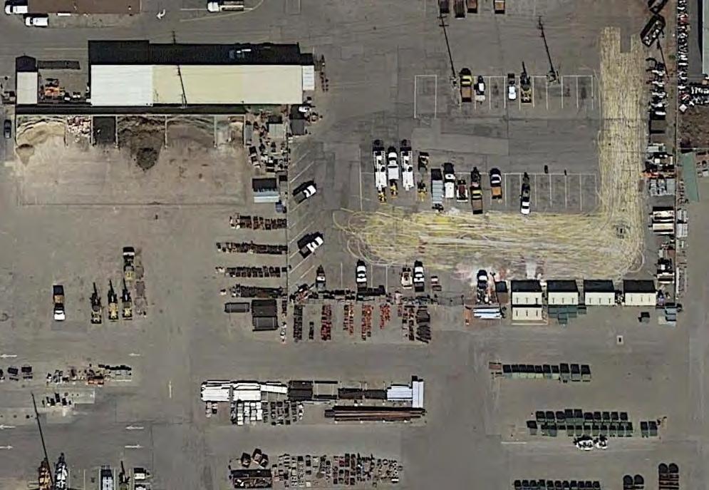
10 Type of Services Project Name Location Geotechnical Investigation City of Santa Clara Corp Yard Water Tank 1900 Walsh Avenue Santa Clara, California SECTION 1: INTRODUCTION This geotechnical report was prepared for the sole use of GHD for the City of Santa Clara Corp Yard Water Tank in Santa Clara, California. The location of the site is shown on the Vicinity Map, Figure 1. For our use, we were provided with the following documents: Portion of Aerial Photo with tank location superimposed, undated, untitled. Geotechnical Investigation, Proposed Pedestal Tower Water Tank, Walsh Road, Santa Clara, California, prepared by Bay Area Geotechnical Group, dated April 14, PROJECT DESCRIPTION The project will consist of construction of a 2-million-gallon water tank within the City of Santa Clara Corporation Yard surrounded by an access road. The water tank will be of welded steelframe construction. Additional piping and a small pump house building are also planned. Average areal loads are anticipated to be on the order of 2,200 psf under the tank footprint, while the pump building may have loads of up to 2 kips per lineal foot along a continuous perimeter footing. Grading is anticipated to be minor, with cuts and fills on the order of 1 to 3 feet. 1.2 SCOPE OF SERVICES Our scope of services was presented in our proposal dated June 19, 2014 and consisted of field and laboratory programs to evaluate physical and engineering properties of the subsurface soils, engineering analysis to prepare recommendations for site work and grading, building foundations, flatwork, retaining walls, and pavements, and preparation of this report. Brief descriptions of our exploration and laboratory programs are presented below. CITY OF SANTA CLARA CORP YARD WATER TANK Page 1
11 1.3 EXPLORATION PROGRAM Field exploration consisted of two borings drilled on July 2, 2014 with truck-mounted, hollowstem auger drilling equipment and two (2) Cone Penetration Tests (CPTs) advanced on June 27, The borings were drilled to depths of 15 to 45 feet; the CPTs were advanced to depths of 50 to 75 feet. One of the borings (Boring EB-1) was advanced adjacent to CPT-1 for direct evaluation of physical samples to correlated soil behavior. The borings and CPTs were backfilled with cement grout in accordance with local requirements; exploration permits were obtained as required by local jurisdictions. The approximate locations of our exploratory borings are shown on the Site Plan, Figure 2. Details regarding our field program are included in Appendix A. 1.4 LABORATORY TESTING PROGRAM In addition to visual classification of samples, the laboratory program focused on obtaining data for foundation design and seismic ground deformation estimates. Testing included moisture contents, dry densities, washed sieve analyses, Plasticity Index tests, and consolidation tests. Details regarding our laboratory program are included in Appendix B. 1.5 ENVIRONMENTAL SERVICES Environmental services were not requested for this project. If environmental concerns are determined to be present during future evaluations, the project environmental consultant should review our geotechnical recommendations for compatibility with the environmental concerns. SECTION 2: REGIONAL SETTING 2.1 GEOLOGICAL SETTING The site is located within the Santa Clara Valley, which is a broad alluvial plane between the Santa Cruz Mountains to the southwest and west, and the Diablo Range to the northeast. The San Andreas Fault system, including the Monte Vista-Shannon Fault, exists within the Santa Cruz Mountains and the Hayward and Calaveras Fault systems exist within the Diablo Range. Alluvial soil thicknesses in the area of Santa Clara and north San Jose range from about 300 to greater than 700 feet (Rogers & Williams, 1974). 2.2 REGIONAL SEISMICITY The San Francisco Bay area is one of the most seismically active areas in the Country. While seismologists cannot predict earthquake events, the U.S. Geological Survey s Working Group on California Earthquake Probabilities 2007 estimates there is a 63 percent chance of at least one magnitude 6.7 or greater earthquake occurring in the Bay Area region between 2007 and As seen with damage in San Francisco and Oakland due to the 1989 Loma Prieta earthquake that was centered about 50 miles south of San Francisco, significant damage can Page 2
12 occur at considerable distances. Higher levels of shaking and damage would be expected for earthquakes occurring at closer distances. The faults considered capable of generating significant earthquakes are generally associated with the well-defined areas of crustal movement, which trend northwesterly. The table below presents the State-considered active faults within 25 kilometers of the site. Table 1: Approximate Fault Distances Fault Name (miles) Distance (kilometers) Hayward (Southeast Extension) Monte Vista-Shannon Hayward (Total Length) Calaveras San Andreas (1906) A regional fault map is presented as Figure 3, illustrating the relative distances of the site to significant fault zones. SECTION 3: SITE CONDITIONS 3.1 SURFACE DESCRIPTION The site is located in the existing City of Santa Clara Corporation Yard. The area where the tank is proposed is relatively flat and paved with asphaltic concrete. From our site visit observations, most of the site is currently used as a storage area for extra materials and city maintenance vehicle parking. Surface pavements generally consisted of 2 inches of asphalt concrete over 6½ to 7½ inches of aggregate base. Based on visual observations, the existing pavements are in good condition. 3.2 SUBSURFACE CONDITIONS Below the surface pavements, our explorations generally encountered hard to very stiff, high plasticity clays to between 7 and 9 feet underlain by several feet of stiff to very stiff lean clay. In EB-1 we encountered 6 feet of medium dense sand with variable amounts of fines and gravels from 11 to 17 feet below grade. Below this, we encountered stiff to very stiff high plasticity clay to approximately 23 feet followed by stiff to very stiff lean clay with some thin layers of medium dense clayey sand to the terminal depth of the boring at 45 feet. Below the maximum depth of our borings, our CPT s encountered two dense layers of sand, ranging from about 6 to 7 feet thick, with correlated SPT blow counts of 40 to 50 per foot, beginning at 43 feet and 56 feet, respectively. These sands were underlain by stiff clays to 75 feet, the maximum depth explored. Page 3
13 3.2.1 Plasticity/Expansion Potential We performed one Plasticity Index (PI) tests on a representative sample of near-surface soil to evaluate the expansion potential of surficial soils. Results of the surficial PI test indicated a PI of 31, indicating high expansion potential to wetting and drying cycles In-Situ Moisture Contents Laboratory testing indicated that the in-situ moisture contents within the upper 10 feet range from 6 to 14 percent over the estimated laboratory optimum moisture Sulfate Contents Laboratory testing indicated that the soluble sulfate contents were 42 ppm, indicating negligible corrosion potential to buried concrete. 3.3 GROUND WATER Ground water was encountered in some of our explorations, including EB-1, EB-2, and also inferred by a pore pressure dissipation test in CPT-2, at depths ranging from 8½ to 10 feet below current grades. All measurements were taken at the time of drilling and may not represent the stabilized levels that can be higher than the initial levels encountered. CGS has mapped the historic high ground water in this area at approximately 10 feet; however, a previous geotechnical investigation at the site encountered high ground water at 8 feet below grade (BAGG, 2003). We utilized a high ground water level of 7 feet below grade for our liquefaction analysis. Fluctuations in ground water levels occur due to many factors including seasonal fluctuation, underground drainage patterns, regional fluctuations, and other factors. 3.4 CORROSION SCREENING We tested one sample collected at a depth of 3½ feet for resistivity, ph, soluble sulfates, and chlorides. The laboratory test results are summarized in Table 2. Table 2: Summary of Corrosion Test Results Sample/Test Location Number Depth (feet) Soil ph Minimum Resistivity (1) (ohm-cm) Chloride (mg/kg) Sulfate (% dry wt) EB-2/ 2A 3½ 7.9 2, Notes: (1) Laboratory resistivity measured at 100% saturation Many factors can affect the corrosion potential of soil including moisture content, resistivity, permeability, and ph, as well as chloride and sulfate concentration. Typically, soil resistivity, which is a measurement of how easily electrical current flows through a medium (soil and/or Page 4
14 water), is the most influential factor. In addition to soil resistivity, chloride and sulfate ion concentrations, and ph also contribute in affecting corrosion potential Preliminary Soil Corrosion Screening Based on the laboratory test results summarized in Table 2, the soils are considered moderately corrosive to buried metallic improvements (Palmer, 1989). Other corrosion parameters (ph and chloride content) do not indicate a significant contribution to corrosion potential to buried metallic structures. In accordance with the 2013 CBC, Chapter 19, Section , alternative cementitious materials for sulfate exposure shall be in accordance with the following: ACI Table 4.2.1, and Table Based on the laboratory test results, no cement type restriction is required, although, in our opinion, it is generally a good idea to include some sulfate resistance and to maintain a relatively low water-cement ratio. We have summarized applicable design values and parameters from ACI 318, Table below in Table 3 for your information. We recommend the structural engineer and a corrosion engineer be retained to confirm the information provided and for additional recommendations, as required. Table 3: Sulfate Soil Corrosion Design Values and Parameters (1) Category Water-Soluble Sulfate (SO4) in Soil (% by weight) Class Severity Cementitious Materials (2) S, Sulfate < 0.10 S0 not applicable no type restriction Notes: (1) above values and parameters are from on ACI , Table and Table (2) cementitious materials are in accordance with ASTM C150, ASTM C595 and ASTM C1157 SECTION 4: GEOLOGIC HAZARDS 4.1 FAULT RUPTURE As discussed above several significant faults are located within 25 kilometers of the site. The site is not located within a State-designated Alquist Priolo Earthquake Fault Zone, or a Santa Clara County Fault Hazard Zone. As shown in Figure 3, no known surface expression of fault traces is thought to cross the site; therefore, fault rupture hazard is not a significant geologic hazard at the site. 4.2 ESTIMATED GROUND SHAKING Moderate to severe (design-level) earthquakes can cause strong ground shaking, which is the case for most sites within the Bay Area. A peak ground acceleration (PGA) was estimated for analysis using a value equal to F PGA *PGA, as allowed in the 2013 edition of the California Building Code. For our liquefaction analysis we used a PGA of 0.5g. Page 5
15 4.3 LIQUEFACTION POTENTIAL The site is within a State-designated Liquefaction Hazard Zone (CGS, San Jose West Quadrangle, 2003) as well as a Santa Clara County Liquefaction Hazard Zone (Santa Clara County, 2003). Our field and laboratory programs addressed this issue by sampling potentially liquefiable layers to depths of at least 50 feet, performing visual classification on sampled materials, evaluating CPT correlations, and performing various tests to further classify the soil properties Background During strong seismic shaking, cyclically induced stresses can cause increased pore pressures within the soil matrix that can result in liquefaction triggering, soil softening due to shear stress loss, potentially significant ground deformation due to settlement within sandy liquefiable layers as pore pressures dissipate, and/or flow failures in sloping ground or where open faces are present (lateral spreading) (NCEER 1998). Limited field and laboratory data is available regarding ground deformation due to settlement; however, in clean sand layers settlement on the order of 2 to 4 percent of the liquefied layer thickness can occur. Soils most susceptible to liquefaction are loose, non-cohesive soils that are saturated and are bedded with poor drainage, such as sand and silt layers bedded with a cohesive cap Analysis As discussed in the Subsurface section above, several sand layers were encountered below the design ground water depth of 7 feet. Following the procedures in the 2008 monograph, Soil Liquefaction During Earthquakes (Idriss and Boulanger, 2008) and in accordance with CDMG Special Publication 117A guidelines (CDMG, 2008) for quantitative analysis, these layers were analyzed for liquefaction triggering and potential post-liquefaction settlement. These methods compare the ratio of the estimated cyclic shaking (Cyclic Stress Ratio - CSR) to the soil s estimated resistance to cyclic shaking (Cyclic Resistance Ratio - CRR), providing a factor of safety against liquefaction triggering. Factors of safety less than or equal to 1.3 are considered to be potentially liquefiable and capable of post-liquefaction re-consolidation. The CSR for each layer quantifies the stresses anticipated to be generated due to a designlevel seismic event, is based on the peak horizontal acceleration generated at the ground surface discussed in the Estimated Ground Shaking section above, and is corrected for overburden and stress reduction factors as discussed in the procedure developed by Seed and Idriss (1971) and updated in the 2008 Idriss and Boulanger monograph. The soil s CRR is estimated from the in-situ measurements from CPTs and laboratory testing on samples retrieved from our borings. SPT N values obtained from hollow-stem auger borings were not used in our analyses, as the N values obtained are unreliable in sands below ground water. The tip pressures are corrected for effective overburden stresses, taking into consideration both the ground water level at the time of exploration and the design ground water Page 6
16 level, and stress reduction versus depth factors. The CPT method utilizes the soil behavior type index (I C ) to estimate the plasticity of the layers. The results of our CPT analyses (CPT-1 and CPT-2) are presented on Figures 4A and 4B of this report. Calculations for these CPTs are attached as Appendix C Summary Our analyses indicate that several layers could potentially experience liquefaction triggering that could result in soil softening and post-liquefaction total settlement ranging from ½ to 1-inch based on the Yoshimine (2006) method. As discussed in SP 117A, differential movement for level ground sites over deep soil sites will be up to about two-thirds of the total settlement. In our opinion, differential settlements are anticipated to be on the order of ⅔-inch across the tank foundation Ground Rupture Potential The methods used to estimate liquefaction settlements assume that there is a sufficient cap of non-liquefiable material to prevent ground rupture or sand boils. For ground rupture to occur, the pore water pressure within the liquefiable soil layer will need to be great enough to break through the overlying non-liquefiable layer, which could cause significant ground deformation and settlement. The work of Youd and Garris (1995) indicates that the 10-foot thick layer of non-liquefiable cap is sufficient to prevent ground rupture; therefore, ground rupture is not expected and the above total settlement estimates are reasonable. 4.4 LATERAL SPREADING Lateral spreading is horizontal/lateral ground movement of relatively flat-lying soil deposits towards a free face such as an excavation, channel, or open body of water; typically lateral spreading is associated with liquefaction of one or more subsurface layers near the bottom of the exposed slope. As failure tends to propagate as block failures, it is difficult to analyze and estimate where the first tension crack will form. There are no open faces within a distance considered susceptible to lateral spreading; therefore, in our opinion, the potential for lateral spreading to affect the site is low. 4.5 SEISMIC SETTLEMENT/UNSATURATED SAND SHAKING Loose unsaturated sandy soils can settle during strong seismic shaking. As the unsaturated soils encountered at the site were predominantly very stiff clays, in our opinion, the potential for significant differential seismic settlement affecting the proposed improvements is low. Page 7
17 4.6 FLOODING Based on our internet search of the Federal Emergency Management Agency (FEMA) flood map public database, the site is located within Zone X, an area described as an area of 0.2% annual chance flood; area of 1% annual chance flood with average depth of less than 1 foot or with drainage areas less than 1 square mile; and areas protected by levees from 1% annual chance flood. We recommend the project civil engineer be retained to confirm this information and verify the base flood elevation, if appropriate. The Association of Bay Area Governments has compiled a database of Dam Failure Inundation Hazard Maps (ABAG, 1995). The generalized hazard maps were prepared by dam owners as required by the State Office of Emergency Services; they are intended for planning purposes only. Based on our review of these maps, the site is not located within a dam failure inundation area. SECTION 5: CONCLUSIONS 5.1 SUMMARY From a geotechnical viewpoint, the project is feasible provided the concerns listed below are addressed in the project design. Descriptions of each concern with brief outlines of our recommendations follow the listed concerns. Potential for liquefaction-induced settlements Potential for significant static and seismic settlements Shallow ground water Presence of moderately expansive soils Soil corrosion potential Potential for Liquefaction-Induced Settlements As discussed, our liquefaction analysis indicates that there is a potential for liquefaction of localized sand layers during a significant seismic event. Although the potential for liquefied sands to vent to the ground surface through cracks in the surficial soils is low, our analysis indicates that liquefaction-induced settlement on the order of ½- to 1-inch could occur, resulting in differential settlement up to ⅔-inch across the tank foundation. Based on our review and discussions with you of the preliminary foundation loads, it should be feasible to support the proposed buildings on shallow foundations; however, the building foundations will need to be designed to tolerate the total and differential settlement due to static loads and liquefactioninduced settlement. Detailed foundation recommendations are presented in the Foundations section. Page 8
18 5.1.2 Potential for Significant Static and Seismic Settlements As previously mentioned, the project will be a large water tank at a site with high ground water. As most of the subsurface soils were clayey, we anticipate there may be significant static settlements from the project loading over the project life-span. If shallow foundations are utilized, consolidation of the underlying saturated soil may result in static settlements on the order of 2 inches or more depending on the geometry of the tank layout. Further recommendations are presented in the foundations section of this report Shallow Ground Water Shallow ground water was measured at depths ranging from approximately 8½ to 10 feet below the existing ground surface. Our experience with similar sites in the vicinity indicates that shallow ground water could significantly impact grading and underground construction. These impacts typically consist of potentially wet and unstable pavement subgrade, difficulty achieving compaction, and difficult underground utility installation. Dewatering and shoring of utility trenches may be required in some isolated areas of the site where excavations exceed about 7 feet below existing grade. Detailed recommendations addressing this concern are presented in the Earthwork section of this report Expansive Soils Highly expansive surficial soils generally blanket the site. Expansive soils can undergo significant volume change with changes in moisture content. They shrink and harden when dried and expand and soften when wetted. To reduce the potential for damage to the planned structures, slabs-on-grade should have sufficient reinforcement and be supported on a layer of non-expansive fill; footings should extend below the zone of seasonal moisture fluctuation. In addition, it is important to limit moisture changes in the surficial soils by using positive drainage away from buildings as well as limiting landscaping watering. Detailed grading and foundation recommendations addressing this concern are presented in the following sections Soil Corrosion Potential A preliminary soil corrosion screening was performed based on the results of analytical tests on samples of the near-surface soil. In general, the results show that the corrosion potential for buried metallic structures, such as metal pipes, is considered corrosive. As the preliminary soil corrosion screening was based on the results of limited sampling, consideration may be given to collecting and testing additional samples from the upper 5 feet for sulfates and ph to confirm the classification of corrosive to mortar coated steel and concrete. Page 9
19 5.2 PLANS AND SPECIFICATIONS REVIEW We recommend that we be retained to review the geotechnical aspects of the project structural, civil, and landscape plans and specifications, allowing sufficient time to provide the design team with any comments prior to issuing the plans for construction. 5.3 CONSTRUCTION OBSERVATION AND TESTING As site conditions may vary significantly between the small-diameter borings performed during this investigation, we also recommend that a Cornerstone representative be present to provide geotechnical observation and testing during earthwork and foundation construction. This will allow us to form an opinion and prepare a letter at the end of construction regarding contractor compliance with project plans and specifications, and with the recommendations in our report. We will also be allowed to evaluate any conditions differing from those encountered during our investigation, and provide supplemental recommendations as necessary. For these reasons, the recommendations in this report are contingent of Cornerstone providing observation and testing during construction. Contractors should provide at least a 48-hour notice when scheduling our field personnel. SECTION 6: EARTHWORK 6.1 SITE DEMOLITION, CLEARING AND PREPARATION Demolition of Existing Slabs, Foundations and Pavements All slabs, foundations, and pavements should be completely removed from within planned building areas. A discussion of recycling existing improvements is provided later in this report Abandonment of Existing Utilities All utilities should be completely removed from within planned tank footprint. For any utility line to be considered acceptable to remain within the tank building area, the utility line must be completely backfilled with grout or sand-cement slurry (sand slurry is not acceptable), the ends outside the building area capped with concrete, and the trench fills either removed and replaced as engineered fill with the trench side slopes flattened to at least 1:1, or the trench fills are determined not to be a risk to the structure. The assessment of the level of risk posed by the particular utility line will determine whether the utility may be abandoned in place or needs to be completely removed. The contractor should assume that all utilities will be removed from within building areas unless provided written confirmation from both the owner and the geotechnical engineer. Utilities extending beyond the building area may be abandoned in place provided the ends are plugged with concrete, they do not conflict with planned improvements, and that the trench fills do not pose significant risk to the planned surface improvements. Page 10
20 The risks associated with abandoning utilities in place include the potential for future differential settlement of existing trench fills, and/or partial collapse and potential ground loss into utility lines that are not completely filled with grout. In general, the risk is relatively low for single utility lines less than 4 inches in diameter, and increases with increasing pipe diameter. 6.2 REMOVAL OF EXISTING FILLS While fills were not encountered in our borings, any fills encountered during site grading should be completely removed from within building areas and to a lateral distance of at least 5 feet beyond the tank footprint or to a lateral distance equal to fill depth below the perimeter footing, whichever is greater. Provided the fills meet the Material for Fill requirements below, the fills may be reused when backfilling the excavations. Based on review of the samples collected from our borings, it appears that the fill may be reused. If materials are encountered that do not meet the requirements, such as debris, wood, trash, those materials should screened out of the remaining material and be removed from the site. Backfill of excavations should be placed in lifts and compacted in accordance with the Compaction section below. Fills extending into planned pavement and flatwork areas may be left in place provided they are determined to be a low risk for future differential settlement and that the upper 12 to 18 inches of fill below pavement subgrade is re-worked and compacted as discussed in the Compaction section below. 6.3 TEMPORARY CUT AND FILL SLOPES The contractor is responsible for maintaining all temporary slopes and providing temporary shoring where required. Temporary shoring, bracing, and cuts/fills should be performed in accordance with the strictest government safety standards. On a preliminary basis, the upper 10 feet at the site may be classified as OSHA Soil Class B materials. Excavations performed during site demolition and fill removal should be sloped at 3:1 (horizontal:vertical) within the upper 5 feet below foundation subgrade. Excavations extending more than 5 feet below building subgrade and excavations in pavement and flatwork areas should be sloped or benched in accordance with OSHA regulations. 6.4 SUBGRADE PREPARATION After site clearing and demolition is complete, and prior to backfilling any excavations resulting from fill removal or demolition, the excavation subgrade and subgrade within areas to receive additional site fills, slabs-on-grade and/or pavements should be scarified to a depth of 6 inches, moisture conditioned, and compacted in accordance with the Compaction section below. 6.5 SUBGRADE STABILIZATION MEASURES Soil subgrade and fill materials, especially soils with high fines contents such as clays and silty soils, can become unstable due to high moisture content, whether from high in-situ moisture contents or from winter rains. As the moisture content increases over the laboratory optimum, it Page 11
21 becomes more likely the materials will be subject to softening and yielding (pumping) from construction loading or become unworkable during placement and compaction. As discussed in the Subsurface section in this report, the in-situ moisture contents are about 6 to 14 percent over the estimated laboratory optimum in the upper 10 of the soil profile. The contractor should anticipate drying the soils prior to reusing them as fill. In addition, repetitive rubber-tire loading will likely de-stabilize the soils. There are several methods to address potential unstable soil conditions and facilitate fill placement and trench backfill. Some of the methods are briefly discussed below. Implementation of the appropriate stabilization measures should be evaluated on a case-bycase basis according to the project construction goals and the particular site conditions Scarification and Drying The subgrade may be scarified to a depth of about 12 inches and allowed to dry to near optimum conditions, if sufficient dry weather is anticipated to allow sufficient drying. More than one round of scarification may be needed to break up the soil clods Removal and Replacement As an alternative to scarification, the contractor may choose to over-excavate the unstable soils and replace them with dry on-site or import materials. A Cornerstone representative should be present to provide recommendations regarding the appropriate depth of over-excavation, whether a geosynthethic (stabilization fabric or geogrid) is recommended, and what materials are recommended for backfill Chemical Treatment Where the unstable area exceeds about 5,000 to 10,000 square feet and/or site winterization is desired, chemical treatment with quicklime (CaO), kiln-dust, or cement may be more costeffective than removal and replacement. Recommended chemical treatment depths will typically range from 12 to 18 inches depending on the magnitude of the instability. 6.6 MATERIAL FOR FILL Re-Use of On-site Soils On-site soils with an organic content less than 3 percent by weight may be reused as general fill. General fill should not have lumps, clods or cobble pieces larger than 6 inches in diameter; 85 percent of the fill should be smaller than 2½ inches in diameter. Minor amounts of oversize material (smaller than 12 inches in diameter) may be allowed provided the oversized pieces are not allowed to nest together and the compaction method will allow for loosely placed lifts not exceeding 12 inches. Page 12
22 6.6.2 Re-Use of On-Site Site Improvements We anticipate that significant quantities of asphalt concrete (AC) grindings and aggregate base (AB) will be generated during site demolition. If the AC grindings are mixed with the underlying AB to meet Class 2 AB specifications, they may be reused within the new pavement and flatwork structural sections, including under the tank as part of a non-expansive layer. Laboratory testing will be required to confirm the grindings meet project specifications Potential Import Sources Imported and non-expansive material should be inorganic with a Plasticity Index (PI) of 15 or less. To prevent significant caving during trenching or foundation construction, imported material should have sufficient fines. Samples of potential import sources should be delivered to our office at least 10 days prior to the desired import start date. Information regarding the import source should be provided, such as any site geotechnical reports. If the material will be derived from an excavation rather than a stockpile, potholes will likely be required to collect samples from throughout the depth of the planned cut that will be imported. At a minimum, laboratory testing will include PI tests. Material data sheets for select fill materials (Class 2 aggregate base, ¾-inch crushed rock, quarry fines, etc.) listing current laboratory testing data (not older than 6 months from the import date) may be provided for our review without providing a sample. If current data is not available, specification testing will need to be completed prior to approval. Environmental and soil corrosion characterization should also be considered by the project team prior to acceptance. Suitable environmental laboratory data to the planned import quantity should be provided to the project environmental consultant; additional laboratory testing may be required based on the project environmental consultant s review. The potential import source should also not be more corrosive than the on-site soils, based on ph, saturated resistivity, and soluble sulfate and chloride testing Non-Expansive Fill Using Lime Treatment As discussed above, non-expansive fill should have a Plasticity Index (PI) of 15 or less. Due to the high clay content and PI of the on-site soil materials, it is not likely that sufficient quantities of non-expansive fill would be generated from onsite materials. As an alternative to importing non-expansive fill, chemical treatment can be considered to create non-expansive fill. It has been our experience that high PI clayey soil will likely need to be mixed with 3½ to 4 percent quicklime (CaO) or approved alternative to adequately reduce the PI of the on-site soils to 15 or less. If this option is considered, additional laboratory tests should be performed during initial site grading to further evaluate the optimum percentage of quicklime required. 6.7 COMPACTION REQUIREMENTS All fills, and subgrade areas where fill, slabs-on-grade, and pavements are planned, should be placed in loose lifts 8 inches thick or less and compacted in accordance with ASTM D1557 (latest version) requirements as shown in the table below. In general, clayey soils should be Page 13
23 compacted with sheepsfoot equipment and sandy/gravelly soils with vibratory equipment; opengraded materials such as crushed rock should be placed in lifts no thicker than 18 inches consolidated in place with vibratory equipment. Each lift of fill and all subgrade should be firm and unyielding under construction equipment loading in addition to meeting the compaction requirements to be approved. The contractor (with input from a Cornerstone representative) should evaluate the in-situ moisture conditions, as the use of vibratory equipment on soils with high moistures can cause unstable conditions. General recommendations for soil stabilization are provided in the Subgrade Stabilization Measures section of this report. Where the soil s PI is 20 or greater, the expansive soil criteria should be used. Table 4: Compaction Requirements Description Material Description Minimum Relative 1 Compaction (percent) Moisture 2 Content (percent) General Fill On-Site Expansive Soils >3 (within upper 5 feet) Low Expansion Soils 90 >1 Trench Backfill On-Site Expansive Soils >3 Trench Backfill Low Expansion Soils 90 >1 Crushed Rock Fill ¾-inch Clean Crushed Rock Consolidate In-Place NA Non-Expansive Fill Imported Non-Expansive Fill 90 Optimum Flatwork Subgrade On-Site Expansive Soils >3 Flatwork Subgrade Low Expansion Soils 90 >1 Flatwork Aggregate Base Class 2 Aggregate Base 3 90 Optimum Pavement Subgrade On-Site Expansive Soils >3 Pavement Subgrade Low Expansion Soils 95 >1 Pavement Aggregate Base Class 2 Aggregate Base 3 95 Optimum Asphalt Concrete Asphalt Concrete 95 (Marshall) NA 1 Relative compaction based on maximum density determined by ASTM D1557 (latest version) 2 Moisture content based on optimum moisture content determined by ASTM D1557 (latest version) 3 Class 2 aggregate base shall conform to Caltrans Standard Specifications, latest edition, except that the relative compaction should be determined by ASTM D1557 (latest version) Page 14
24 6.7.1 Construction Moisture Conditioning Expansive soils can undergo significant volume change when dried then wetted. The contractor should keep all exposed expansive soil subgrade (and also trench excavation side walls) moist until protected by overlying improvements (or trenches are backfilled). If expansive soils are allowed to dry out significantly, re-moisture conditioning may require several days of re-wetting (flooding is not recommended), or deep scarification, moisture conditioning, and re-compaction. 6.8 TRENCH BACKFILL Utility lines constructed within public right-of-way should be trenched, bedded and shaded, and backfilled in accordance with the local or governing jurisdictional requirements. Utility lines in private improvement areas should be constructed in accordance with the following requirements unless superseded by other governing requirements. All utility lines should be bedded and shaded to at least 6 inches over the top of the lines with crushed rock (⅜-inch-diameter or greater) or well-graded sand and gravel materials conforming to the pipe manufacturer s requirements. Open-graded shading materials should be consolidated in place with vibratory equipment and well-graded materials should be compacted to at least 90 percent relative compaction with vibratory equipment prior to placing subsequent backfill materials. General backfill over shading materials may consist of on-site native materials provided they meet the requirements in the Material for Fill section, and are moisture conditioned and compacted in accordance with the requirements in the Compaction section. Where utility lines will cross perpendicular to strip footings, the footing should be deepened to encase the utility line, providing sleeves or flexible cushions to protect the pipes from anticipated foundation settlement, or the utility lines should be backfilled to the bottom of footing with sandcement slurry or lean concrete. Where utility lines will parallel footings and will extend below the foundation plane of influence, an imaginary 1:1 plane projected down from the bottom edge of the footing, either the footing will need to be deepened so that the pipe is above the foundation plane of influence or the utility trench will need to be backfilled with sand-cement slurry or lean concrete within the influence zone. Sand-cement slurry used within foundation influence zones should have a minimum compressive strength of 75 psi. 6.9 SITE DRAINAGE Ponding should not be allowed adjacent to building foundations, slabs-on-grade, or pavements. Hardscape surfaces should slope at least 2 percent towards suitable discharge facilities; landscape areas should slope at least 3 percent towards suitable discharge facilities. Roof runoff should be directed away from building areas in closed conduits, to approved infiltration facilities, or on to hardscaped surfaces that drain to suitable facilities. Retention, detention or infiltration facilities should be spaced at least 10 feet from buildings, and preferably at least 5 feet from slabs-on-grade or pavements. However, if retention, detention or infiltration facilities Page 15
25 are located within these zones, we recommend that these treatment facilities meet the requirements in the Storm Water Treatment Design Considerations section of this report. SECTION 7: FOUNDATIONS 7.1 SUMMARY OF RECOMMENDATIONS In our opinion, the proposed water tank and pump house structures may be supported on shallow foundations provided the recommendations in the Earthwork section and the sections below are followed and the estimated total and differential settlement due to static loads and seismic hazards are tolerable. Shallow foundations would likely consist of spread footings or mat foundations. Spread footings for a tank may be a ring-type spread footing foundation; often this foundation type also includes an oiled-sand and rock base beneath the central portion of the tank. Deep foundation recommendations are also presented in this section. 7.2 SEISMIC DESIGN CRITERIA We understand that a welded steel water tank is likely; therefore, the project structural design will likely be based on ANSI/AWWA D The ground motion hazard analysis in D has been updated to include the requirements of ASCE 7-05; however, the 2013 California Building Code (CBC) has adopted the more recent ASCE Therefore, we anticipate that the project structural design will be based on the 2013 California Building Code (CBC), which provides criteria for the seismic design of structures in Chapter 16. The Seismic Coefficients used to design structures are established based on a series of tables and figures addressing different site factors, including the soil profile in the upper 100 feet below grade and mapped spectral acceleration parameters based on distance to the controlling seismic source/fault system. Based on our borings and review of local geology, the site is underlain by deep alluvial soils with typical SPT N values between 15 and 50 blows per foot. Therefore, we have classified the site as Soil Classification D. The mapped spectral acceleration parameters S S and S 1 were calculated using the USGS computer program Design Maps, based on the site coordinates presented below and the site classification. The table below lists the various factors used to determine the seismic coefficients and other parameters. Page 16
26 Table 5: CBC Site Categorization and Site Coefficients Classification/Coefficient Site Class Design Value Site Latitude Site Longitude second Period Mapped Spectral Acceleration 1, S S 1.500g 1-second Period Mapped Spectral Acceleration 1, S g Short-Period Site Coefficient Fa 1.0 Long-Period Site Coefficient Fv second Period, Maximum Considered Earthquake Spectral Response Acceleration Adjusted for Site Effects - S MS 1.500g 1-second Period, Maximum Considered Earthquake Spectral Response Acceleration Adjusted for Site Effects S M g 0.2-second Period, Design Earthquake Spectral Response Acceleration S DS 1.000g 1-second Period, Design Earthquake Spectral Response Acceleration S D g 1 For Site Class B, 5 percent damped. D 7.3 SHALLOW FOUNDATIONS Spread Footings Spread footings for the pump house and water tank structures should bear entirely on natural, undisturbed soil or engineered fill, be at least 15 and 18 inches wide, respectively, and extend at least 30 inches below the lowest adjacent grade. Lowest adjacent grade is defined as the deeper of the following: 1) bottom of the adjacent interior slab-on-grade, or 2) finished exterior grade, excluding landscaping topsoil. The deeper footing embedment is due to the presence of highly expansive soils, and is intended to embed the footing below the zone of significant seasonal moisture fluctuation, reducing the potential for differential movement. Footings constructed to the above dimensions and in accordance with the Earthwork recommendations of this report are capable of supporting maximum allowable bearing pressures of 2,000 psf for dead loads, 3,000 psf for combined dead plus live loads, and 4,000 psf for all loads including wind and seismic. These pressures are based on factors of safety of 3.0, 2.0, and 1.5 applied to the ultimate bearing pressure for dead, dead plus live, and all loads, respectively. These pressures are net values; the weight of the footing may be neglected for the portion of the footing extending below grade (typically, the full footing depth). Top and bottom mats of reinforcing steel should be included in continuous footings to help span irregularities and differential settlement. Page 17
27 7.3.2 Footing Settlement Structural loads were not provided to us at the time this report was prepared; therefore, we assumed the typical loading in the following table. Table 6: Assumed Structural Loading Foundation Area Ring Foundation (Water Tank) Perimeter Strip Footing (Pump House) Range of Assumed Loads 4 to 6 kips per lineal foot 1 kip per lineal foot Based on the above loading and the allowable bearing pressures presented above, we estimate that the total static footing settlement for the pump house will be on the order of ⅓-inch, with less than about ¼-inch of post-construction differential settlement between adjacent foundation elements. For the water tank, settlement will affect the entirety of the tank area. We estimate static settlement to be on the order of 3 inches, with about 1¾-inches of differential settlement. In addition we estimate that differential seismic movement will be on the order of ⅔-inch over a horizontal distance of 30 feet, resulting in a total estimated differential footing movement of ¾- inch between foundation elements for the pump house, and 2½-inches over the tank area. As our footing loads were assumed, we recommend we be retained to review the final footing layout and loading, and verify the settlement estimates above Lateral Loading Lateral loads may be resisted by friction between the bottom of footing and the supporting subgrade, and also by passive pressures generated against footing sidewalls. An ultimate frictional resistance of 0.4 applied to the footing dead load, and an ultimate passive pressure based on an equivalent fluid pressure of 400 pcf may be used in design. The structural engineer should apply an appropriate factor of safety (such as 1.5) to the ultimate values above. Where footings are adjacent to landscape areas without hardscape, the upper 12 inches of soil should be neglected when determining passive pressure capacity Spread Footing Construction Considerations Where utility lines will cross perpendicular to strip footings, the footing should be deepened to encase the utility line, providing sleeves or flexible cushions to protect the pipes from anticipated foundation settlement, or the utility lines should be backfilled to the bottom of footing with sandcement slurry or lean concrete. Where utility lines will parallel footings and will extend below the foundation plane of influence, an imaginary 1:1 plane projected down from the bottom edge of the footing, either the footing will need to be deepened so that the pipe is above the foundation plane of influence or the utility trench will need to be backfilled with sand-cement slurry or lean concrete within the influence zone. Sand-cement slurry used within foundation influence zones should have a minimum compressive strength of 75 psi. Page 18
28 Footing excavations should be filled as soon as possible or be kept moist until concrete placement by regular sprinkling to prevent desiccation. A Cornerstone representative should observe all footing excavations prior to placing reinforcing steel and concrete. If there is a significant schedule delay between our initial observation and concrete placement, we may need to re-observe the excavations Reinforced Concrete Mat Foundations The water tank may be supported on a mat foundations bearing on natural soil or engineered fill prepared in accordance with the Earthwork section of this report, and designed in accordance with the recommendations below. Due to the presence of highly expansive soils at the site, we recommend that the upper 18 inches below mat foundations consist of non-expansive fill. For design, we assumed average areal bearing pressures of 2200 psf for the water tank; we should be forwarded the final structural loading to check our settlement estimates. This bearing pressure is a net value; the weight of the mat may be neglected for the portion of the mat extending below grade. When evaluating wind and seismic conditions, allowable bearing pressures may be increased by one-third. Top and bottom mats of reinforcing steel should be included in the mat to help span irregularities and resist differential settlement Mat Foundation Settlement The estimated static settlement for the tank is 3inches over the footprint of the mat. In addition to the estimated differential static settlements of 1½-inches across the mat area for reinforced concrete mats, the mats should be designed to accommodate an estimated seismic differential movement of ⅔-inch across the mat for a total differential settlement of approximately 2¼inches Lateral Loading Lateral loads may be resisted by friction between the bottom of mat foundation and the supporting subgrade, and also by passive pressures generated against deepened mat edges. An ultimate frictional resistance of 0.4 applied to the mat dead load, and an ultimate passive pressure based on an equivalent fluid pressure of 400 pcf may be used in design. The structural engineer should apply an appropriate factor of safety (such as 1.5) to the ultimate values above. The upper 12 inches of soil should be neglected when determining passive pressure capacity Mat Foundation Construction Considerations Due to the presence of expansive soils, mat subgrade areas should be kept moist until concrete placement by regular sprinkling to prevent desiccation. If deep drying is allowed to occur, several days of moisture conditioning (flooding of the pads is not recommended) may be required to allow the moisture to re-penetrate the subgrade. If severe drying occurs, reworking and moisture conditioning of the pad may be required. Prior to mat construction, the subgrade should be proof-rolled and visually observed by a Cornerstone representative to confirm stable subgrade conditions. The pad moisture should also be checked at least 24 hours prior to vapor Page 19
29 barrier or mat reinforcement placement to confirm that the soil has a moisture content of at least 3 percent over optimum in the upper 12 inches Mat Modulus of Soil Subgrade Reaction The modulus value of soil subgrade reaction is a model element that represents the response to a specific loading condition, including the magnitude, rate, and shape of loading, given the subsurface conditions at that location. Based on an assumed diameter of 103 feet with contact pressures on the order of 2,200 psf, our analyses indicated a modulus of 10 pci to be appropriate for design. 7.4 DEEP FOUNDATIONS Driven Piles The proposed water tank may be supported on driven, pre-cast, pre-stressed (PCPS) concrete friction piles. Adjacent pile centers should be spaced at least three diameters apart, otherwise, a reduction for group effects may be required. Grade beams should span between piles in accordance with structural requirements. Conventional mat slab may be used to distribute the load across the piles provided the subgrade soils are prepared in accordance with the Earthwork section Vertical Capacity and Estimated Settlement As no significantly thick or continuous dense sand layer was encountered during our investigation that would provide adequate end bearing support, vertical capacity is based on frictional resistance. We evaluated the allowable vertical capacity for 12- and 14-inch-square concrete piles and presented the results in Figure 4. As shown in Figure 4, we have assumed that the top of pile/bottom of pile cap occurs at 2 feet below existing site grades. The allowable capacities are for dead plus live loads using a factor of safety of 2.0; dead loads should not exceed two-thirds of the allowable capacities. The allowable capacities may be increased by one-third for wind and seismic loads. Uplift loads should not exceed 75 percent of the allowable downward vertical capacity under seismic loading. Gross capacity of the piles should be less than the structural capacity, estimated to be 250 and 344 kips for typical 12- and 14-inch-square PCPS piles, respectively (Sante Fe-Pomery, Inc.) Total settlement of individual piles should not exceed ½-inch to mobilize static capacities and post-construction differential settlement over a horizontal distance of 30 feet should not exceed ½-inch due to static loads Lateral Capacity Lateral load resistance is developed by the soil s resistance to pile bending. The magnitude of the shear and bending moment developed within the pile are dependent on the pile stiffness, embedment length, the fixity of the pile into the pile cap (free or fixed-head conditions), the Page 20
30 surrounding soil properties, the tolerable lateral deflection, and yield moment capacity of the pile. We utilized the computer program L-Pile to model the load-deflection (p-y) curves representing the soil conditions surrounding the pile, and estimate the ultimate lateral load capacity of the pile. The following table presents the probable response of the piles under short-term loading conditions; the structural engineer should apply an appropriate factor of safety on the shears and moments presented. Pile stiffnesses (EI) of 7.34 x 10 9 lb-in 2 and 13.7 x 10 9 lb-in 2 have been assumed in our analysis for 12- and 14-inch piles, respectively. We assumed a concrete compressive strength of 6,000 psi for the concrete modulus calculations. If the pile stiffness varies by less than 20 percent of our assumed stiffness, the lateral load parameters below may be interpolated by multiplying the values by the ratio of the different pile stiffness values. We should be retained to re-evaluate the lateral load capacity for piles with a stiffness significantly different from what was assumed. Table 7: Ultimate Lateral Load Capacity Driven Piles Pile Type Fixity Condition Lateral Deflection (inches) Maximum Shear (kips) Maximum Moment (kip-feet) Depth to Maximum Moment (feet) Depth to Zero Moment (feet) 12-inch Fixed-Head Square inch Fixed-Head Square The above lateral capacities are for single piles and may not be representative of piles in groups. Group effects, including the layout of the piles within a group, can significantly reduce the overall lateral capacity. For pile groups we should be retained to evaluate what appropriate group efficiency reduction factors should be applied to the different group conditions Passive Resistance against Pile Caps and Grade Beams Passive resistance against pile caps and grade beams poured neat against native or engineered fill may also be considered; however, as the allowable lateral deflections of the piles are limited, full allowable passive will not be developed. We should be retained to work with the structural engineer to evaluate appropriate allowable passive pressures that maintain strain compatibility between the piles and pile caps Pre-Production Test Program Prior to construction of production piles, a pre-production test program should be undertaken, including a WEAP analysis, developing an indicator pile program, and performance of PDA monitoring during indicator pile construction. Page 21
31 WEAP Analysis We recommend that the pile contractor have a wave equation analysis of piles (WEAP) performed. A WEAP analysis will evaluate the drivability of different pile driving systems taking into consideration the desired pile types, typical pile driving hammers and cushions, and the site soil conditions, especially any relatively thick sand layers. We should be retained to review the WEAP analysis results prior to the start of indicator or production pile construction Indicator Pile Program Due to the variability of the site soil conditions, we recommend that we be retained to review the structural plans and develop an indicator pile program based on the proposed pile locations. This program will target both the areas where the weakest soil conditions were encountered, as well as where sand layers were encountered that are likely to induce high driving stresses within the piles. The indicator pile program will be used to more accurately estimate final pile lengths and determine whether piles can be driven through the sand layers encountered. We recommend that at least 2 indicator piles be installed prior to finalizing pile cast lengths. The indicator piles should be cast to lengths estimated to meet the desired capacity plus an extra 5 feet in case the desired capacity is not met at the design length. It is anticipated that the indicator piles will not be driven to their full length; the contractor should plan on cutting some piles to the desired pile butt elevation. The piles should be driven with the same pile driving equipment/hammers that will be used to drive the production piles. Indicator piles are anticipated to meet or exceed the design capacity and so may be used as production piles; therefore, the indicator piles locations should be surveyed in place PDA Monitoring We also recommend that a pile driving analyzer (PDA) be used during the indicator pile program to evaluate the as-driven pile capacity through dynamic testing. PDA data may indicate that a reduction in production pile lengths is appropriate, providing project cost savings. PDA monitoring should be performed during driving the indicator pile in the weakest soil profile, during driving on all piles selected for re-strikes, and during the re-strikes; piles should be allowed to set up at least seven days prior to re-strike to better define the estimated pile capacity set up curve. PDA monitoring is especially useful during driving piles through significant sand layers to monitor driving stresses and for evaluating pile integrity on any piles suspected of damage. As stand-by costs will be accrued while the pile contractor waits the set-up time for re-strikes, the project structural plans and specifications should clearly indicate the location and number of re-strikes, to avoid unexpected contractor change orders. Page 22
32 Construction Considerations The installation of all indicator and production piles should be observed on a full-time basis by a Cornerstone representative to confirm that the piles are constructed in accordance with our recommendations and project requirements. Since the piles will derive their capacity from skin friction, the production piles should be driven to the design tip elevation. The geotechnical project engineer should review the driving records where any difficult driving and/or refusal conditions are encountered with our field engineer, and evaluate whether there is sufficient tip capacity to allow a length reduction and/or the potential for pile damage. We may recommend performing PDA on any required re-strikes to confirm pile capacity or to evaluate potentially damaged piles during production driving Augercast Piles As an alternative to pre-cast driven concrete piles, drilled, cast-in-place displacement augercast piles may be used. Augercast piles are concrete piles that are cast in place using a hollow-stem auger that drills to the design depth and then the sand-cement grout (4,000 to 6,000 psi grout) is pumped through the hollow-stem as the drill stem is extracted. Two types of augercast piles are available: APG piles, which like piers, remove the soil column and replace it with grout; and APGD piles, which displace the soil column as the drill stem is advanced, similar to driven piles, prior to pumping the grout. We anticipate that displacement augercast piles are feasible so that drilling spoils will be minor. Augercast piles are a low noise and vibration installation compared to driven piles. Various types of steel reinforcing, including rebar cages or H-piles may be installed into the still-wet grout after drilling to satisfy bending moment requirements. Vertical and lateral load capacities will be similar to driven piles based on the pile surface area. For example, a 12-inch square pre-cast pile has a similar surface area as a 16-inch round augercast pile, and a 14-inch square pile will be similar to an 18-inch round pile. See Table 8 below for lateral capacities and Figure 5 for the vertical capacities for APG piles. As an alternative, APGD piles will have slightly higher vertical capacities and will have virtually no spoils. We utilized the computer program L-Pile to model the load-deflection (p-y) curves representing the soil conditions surrounding the pile, and estimate the ultimate lateral load capacity of the pile. The following table presents the probable response of the piles under short-term loading conditions; the structural engineer should apply an appropriate factor of safety on the shears and moments presented. Pile stiffness (EI) of 14.2 x 10 9 lb-in 2 have been assumed in our analysis for 16-inch piles, while we assumed a concrete compressive strength of 6,000 psi for the concrete modulus calculations. We should be retained to re-evaluate the lateral load capacity for piles with a stiffness significantly different from what was assumed. Page 23
33 Table 8: Ultimate Lateral Load Capacity APG Piles Pile Type Fixity Condition Lateral Deflection (inches) Maximum Shear (kips) Maximum Moment (kip-feet) Depth to Maximum Moment (feet) Depth to Zero Moment (feet) 16-inch Fixed-Head Round One field pile load test should be performed at a location recommended by the geotechnical engineer. Static load tests include installing a test pile, which can either be in a production pile location or not, with four surrounding piles that serve as anchor piles to resist the jacking pressure. During test pile installation, the contractor should allow for monitoring of the top of pile 10 feet below top of pile, middle, and pile tip. This can be accomplished either with provisions for telltales or strain gauges. This monitoring will allow for observation of the skin friction as it is mobilized. A member of our staff should be present during test pile installation and testing. SECTION 8: CONCRETE SLABS AND PEDESTRIAN PAVEMENTS 8.1 INTERIOR SLABS-ON-GRADE As the Plasticity Index (PI) of the surficial soils ranges up to 31, the proposed slabs-on-grade should be supported on at least 12 inches of non-expansive fill (NEF) to reduce the potential for slab damage due to soil heave. The NEF layer should be constructed over subgrade prepared in accordance with the recommendations in the Earthwork section of this report. If moisturesensitive floor coverings are planned, the recommendations in the Interior Slabs Moisture Protection Considerations section below may be incorporated in the project design if desired. If significant time elapses between initial subgrade preparation and NEF construction, the subgrade should be proof-rolled to confirm subgrade stability, and if the soil has been allowed to dry out, the subgrade should be re-moisture conditioned to at least 3 percent over the optimum moisture content. The structural engineer should determine the appropriate slab reinforcement for the loading requirements and considering the expansion potential of the underlying soils. Consideration should be given to limiting the control joint spacing to a maximum of about 2 feet in each direction for each inch of concrete thickness. 8.2 INTERIOR SLABS MOISTURE PROTECTION CONSIDERATIONS The following general guidelines for concrete slab-on-grade construction where floor coverings are planned are presented for the consideration by the developer, design team, and contractor. These guidelines are based on information obtained from a variety of sources, including the American Concrete Institute (ACI) and are intended to reduce the potential for moisture-related problems causing floor covering failures, and may be supplemented as necessary based on Page 24
34 project-specific requirements. The application of these guidelines or not will not affect the geotechnical aspects of the slab-on-grade performance. Place a minimum 10-mil vapor retarder conforming to ASTM E 1745, Class C requirements or better directly below the concrete slab; the vapor retarder should extend to the slab edges and be sealed at all seams and penetrations in accordance with manufacturer s recommendations and ASTM E 1643 requirements. A 4-inch-thick capillary break, consisting of ½- to ¾-inch crushed rock with less than 5 percent passing the No. 200 sieve, should be placed below the vapor retarder and consolidated in place with vibratory equipment. The capillary break rock may be considered as the upper 4 inches of the non-expansive fill previously recommended. The concrete water:cement ratio should be 0.45 or less. Mid-range plasticizers may be used to increase concrete workability and facilitate pumping and placement. Water should not be added after initial batching unless the slump is less than specified and/or the resulting water:cement ratio will not exceed Polishing the concrete surface with metal trowels is not recommended. Where floor coverings are planned, all concrete surfaces should be properly cured. Water vapor emission levels and concrete ph should be determined in accordance with ASTM F and F requirements and evaluated against the floor covering manufacturer s requirements prior to installation. 8.3 EXTERIOR FLATWORK Exterior concrete flatwork subject to pedestrian and/or occasional light pick up loading should be at least 4 inches thick and supported 6 inches of non-expansive fill overlying subgrade prepared in accordance with the Earthwork recommendations of this report. Flatwork that will be subject to heavier or frequent vehicular loading should be designed in accordance with the recommendations in the Vehicular Pavements section below. To help reduce the potential for uncontrolled shrinkage cracking, adequate expansion and control joints should be included. Consideration should be given to limiting the control joint spacing to a maximum of about 2 feet in each direction for each inch of concrete thickness. Flatwork should be isolated from adjacent foundations or retaining walls except where limited sections of structural slabs are included to help span irregularities in retaining wall backfill at the transitions between at-grade and onstructure flatwork. SECTION 9: VEHICULAR PAVEMENTS 9.1 ASPHALT CONCRETE The following asphalt concrete pavement recommendations tabulated below are based on the Procedure 608 of the Caltrans Highway Design Manual, estimated traffic indices for various Page 25
35 pavement-loading conditions, and on a design R-value of 5. The design R-value was chosen based on engineering judgment considering the variable surface conditions. Table 9: Asphalt Concrete Pavement Recommendations Design Traffic Index (TI) Asphalt Concrete (inches) Class 2 Aggregate Base* (inches) Total Pavement Section Thickness (inches) *Caltrans Class 2 aggregate base; minimum R-value of 78 Frequently, the full asphalt concrete section is not constructed prior to construction traffic loading. This can result in significant loss of asphalt concrete layer life, rutting, or other pavement failures. To improve the pavement life and reduce the potential for pavement distress through construction, we recommend the full design asphalt concrete section be constructed prior to construction traffic loading. Alternatively, a higher traffic index may be chosen for the areas where construction traffic will be use the pavements. 9.2 PORTLAND CEMENT CONCRETE The exterior Portland Cement Concrete (PCC) pavement recommendations tabulated below are based on methods presented in the Portland Cement Association (PCA) design manual (PCA, 1984). Recommendations for garage slabs-on-grade were provided in the Concrete Slabs and Pedestrian Pavements section above. We have provided a few pavement alternatives as an anticipated Average Daily Truck Traffic (ADTT) was not provided. An allowable ADTT should be chosen that is greater than what is expected for the development. Table 10: PCC Pavement Recommendations Minimum PCC Allowable ADTT Thickness (inches) 13 5½ The PCC thicknesses above are based on a concrete compressive strength of at least 3,500 psi, supporting the PCC on at least 6 inches of Class 2 aggregate base compacted as recommended in the Earthwork section, and laterally restraining the PCC with curbs or Page 26
36 concrete shoulders. Adequate expansion and control joints should be included. Consideration should be given to limiting the control joint spacing to a maximum of about 2 feet in each direction for each inch of concrete thickness. Due to the expansive surficial soils present, we recommend that the construction and expansion joints be dowelled. SECTION 10: LIMITATIONS This report, an instrument of professional service, has been prepared for the sole use of GHD specifically to support the design of the City of Santa Clara Corp Yard Water Tank project in Santa Clara, California. The opinions, conclusions, and recommendations presented in this report have been formulated in accordance with accepted geotechnical engineering practices that exist in Northern California at the time this report was prepared. No warranty, expressed or implied, is made or should be inferred. Recommendations in this report are based upon the soil and ground water conditions encountered during our subsurface exploration. If variations or unsuitable conditions are encountered during construction, Cornerstone must be contacted to provide supplemental recommendations, as needed. GHD may have provided Cornerstone with plans, reports and other documents prepared by others. GHD understands that Cornerstone reviewed and relied on the information presented in these documents and cannot be responsible for their accuracy. Cornerstone prepared this report with the understanding that it is the responsibility of the owner or his representatives to see that the recommendations contained in this report are presented to other members of the design team and incorporated into the project plans and specifications, and that appropriate actions are taken to implement the geotechnical recommendations during construction. Conclusions and recommendations presented in this report are valid as of the present time for the development as currently planned. Changes in the condition of the property or adjacent properties may occur with the passage of time, whether by natural processes or the acts of other persons. In addition, changes in applicable or appropriate standards may occur through legislation or the broadening of knowledge. Therefore, the conclusions and recommendations presented in this report may be invalidated, wholly or in part, by changes beyond Cornerstone s control. This report should be reviewed by Cornerstone after a period of three (3) years has elapsed from the date of this report. In addition, if the current project design is changed, then Cornerstone must review the proposed changes and provide supplemental recommendations, as needed. An electronic transmission of this report may also have been issued. While Cornerstone has taken precautions to produce a complete and secure electronic transmission, please check the electronic transmission against the hard copy version for conformity. Recommendations provided in this report are based on the assumption that Cornerstone will be retained to provide observation and testing services during construction to confirm that Page 27
37 conditions are similar to that assumed for design, and to form an opinion as to whether the work has been performed in accordance with the project plans and specifications. If we are not retained for these services, Cornerstone cannot assume any responsibility for any potential claims that may arise during or after construction as a result of misuse or misinterpretation of Cornerstone s report by others. Furthermore, Cornerstone will cease to be the Geotechnical- Engineer-of-Record if we are not retained for these services. SECTION 11: REFERENCES Association of Bay Area Governments (ABAG), 2005, Dam Innudation Map: Boulanger, R.W. and Idriss, I.M., 2004, Evaluating the Potential for Liquefaction or Cyclic Failure of Silts and Clays, Department of Civil & Environmental Engineering, College of Engineering, University of California at Davis. California Building Code, 2013, Structural Engineering Design Provisions, Vol. 2. California Department of Conservation Division of Mines and Geology, 1998, Maps of Known Active Fault Near-Source Zones in California and Adjacent Portions of Nevada, International Conference of Building Officials, February, California Division of Mines and Geology (2008), Guidelines for Evaluating and Mitigating Seismic Hazards in California, Special Publication 117A, September. California Geological Survey, 2003, State of California Seismic Hazard Zones, San Jose West 7.5-Minute Quadrangle, California: Seismic Hazard Zone Report 091. Federal Emergency Management Administration (FEMA), 2009, FIRM City of Santa Clara California, Community Panel #06085C0227H. Idriss, I.M., and Boulanger, R.W., 2008, Soil Liquefaction During Earthquakes, Earthquake Engineering Research Institute, Oakland, CA, 237 p. Portland Cement Association, 1984, Thickness Design for Concrete Highway and Street Pavements: report. Rogers, T.H., and J.W. Williams, 1974 Potential Seismic Hazards in Santa Clara County, California, Special Report No. 107: California Division of Mines and Geology. Seed, H.B. and I.M. Idriss, 1982, Ground Motions and Soil Liquefaction During Earthquakes: Earthquake Engineering Research Institute. State of California Department of Transportation, 2006, Highway Design Manual, Latest Edition. Page 28
38 USGS, 2013, U.S. Seismic Design Maps, revision date April 2, A Computer Program for determining mapped ground motion parameters for use with IBC available at Working Group on California Earthquake Probabilities, 2007, The Uniform Earthquake Rupture Forecast, Version 2 (UCRF 2), U.S.G.S. Open File Report Youd, T.L. and C.T. Garris, 1995, Liquefaction-Induced Ground-Surface Disruption: Journal of Geotechnical Engineering, Vol. 121, No. 11, pp Youd, T.L. and Idriss, I.M., et al, 1997, Proceedings of the NCEER Workshop on Evaluation of Liquefaction Resistance of Soils: National Center for Earthquake Engineering Research, Technical Report NCEER , January 5, 6, Page 29

39
40

41
42 FIGURE 4A CPT NO Cornerstone Earth Group, Inc. PROJECT/CPT DATA CPT ANALYSIS RESULTS Project Title Santa Clara Water Tank DRY SAND SETTLEMENT FROM 7 FEET Project No (Inches) Project Manager PNC LIQUEFACTION SETTLEMENT FROM 50 FEET SEISMIC S PARAMETERS (Inches) Controlling o Fault San Andreas TOTAL SEISMIC SETTLEMENT INCHES Earthquake Magnitude (Mw) 7.9 PGA (Amax) 0.5 (g) POTENTIAL LATERAL DISPLACEMENT SITE SPECIFIC PARAMETERS LDI L/H 0.0 Ground Water Depthp at Time of Drilling g (feet)) 8.5 LDI 1 Corrected for Distance 0.00 (4<L/H<40)( ) Design g Water Depth p (feet)) 7 EXPECTED RANGE OF DISPLACEMENT Ave. Unit Weight Above GW (pcf) to 0.0 feet Ave. Unit Weight Below GW (pcf) Not Valid for L/H Values < 4 and > LDI Values Only Summed to 2H Below Grade. qcn CSR CRR Factor of Safety Cumulative (Liquefaction) Settlement No Liquefaction (fee et) Dep D pth 25 et) ) (fe th De ept 25 (fee et) Dep pth 25 (fe eet) pth Dep D
43 FIGURE 4B CPT NO Cornerstone Earth Group, Inc. PROJECT/CPT DATA CPT ANALYSIS RESULTS Project Title Santa Clara Water Tank DRY SAND SETTLEMENT FROM 7 FEET Project No (Inches) Project Manager PNC LIQUEFACTION SETTLEMENT FROM 50 FEET SEISMIC S PARAMETERS (Inches) Controlling o Fault San Andreas TOTAL SEISMIC SETTLEMENT INCHES Earthquake Magnitude (Mw) 7.9 PGA (Amax) 0.5 (g) POTENTIAL LATERAL DISPLACEMENT SITE SPECIFIC PARAMETERS LDI L/H 0.0 Ground Water Depthp at Time of Drilling g (feet)) 8.5 LDI 1 Corrected for Distance 0.00 (4<L/H<40)( ) Design g Water Depth p (feet)) 7 EXPECTED RANGE OF DISPLACEMENT Ave. Unit Weight Above GW (pcf) to 0.0 feet Ave. Unit Weight Below GW (pcf) Not Valid for L/H Values < 4 and > LDI Values Only Summed to 2H Below Grade. qcn CSR CRR Factor of Safety Cumulative (Liquefaction) Settlement No Liquefaction (fee et) Dep D pth 25 et) ) (fe th De ept 25 (fee et) Dep pth 25 (fe eet) pth Dep D
44
45 APPENDIX A: FIELD INVESTIGATION The field investigation consisted of a surface reconnaissance and a subsurface exploration program using truck-mounted, hollow-stem, auger drilling equipment and 20-ton truck-mounted Cone Penetration Test equipment. Two 8-inch-diameter exploratory borings were drilled on (date) to depths of 15 to 45 feet. Two CPT soundings were also performed in accordance with ASTM D (revised, 2002) on (date), to depths ranging from 50 to 75 feet. The approximate locations of exploratory borings and CPTs are shown on the Site Plan, Figure 2. The soils encountered were continuously logged in the field by our representative and described in accordance with the Unified Soil Classification System (ASTM D2488). Boring logs, as well as a key to the classification of the soil and bedrock, are included as part of this appendix. Boring and CPT locations were approximated using existing site boundaries, and other site features as references. Boring and CPT elevations were not determined. The locations of the borings and CPTs should be considered accurate only to the degree implied by the method used. Representative soil samples were obtained from the borings at selected depths. All samples were returned to our laboratory for evaluation and appropriate testing. The standard penetration resistance blow counts were obtained by dropping a 140-pound hammer through a 30-inch free fall. The 2-inch O.D. split-spoon sampler was driven 18 inches and the number of blows was recorded for each 6 inches of penetration (ASTM D1586). 2.5-inch I.D. samples were obtained using a Modified California Sampler driven into the soil with the 140-pound hammer previously described. Relatively undisturbed samples were also obtained with inch I.D. Shelby Tube sampler which were hydraulically pushed. Unless otherwise indicated, the blows per foot recorded on the boring log represent the accumulated number of blows required to drive the last 12 inches. The various samplers are denoted at the appropriate depth on the boring logs. The CPT involved advancing an instrumented cone-tipped probe into the ground while simultaneously recording the resistance at the cone tip (q c ) and along the friction sleeve (f s ) at approximately 5-centimeter intervals. Based on the tip resistance and tip to sleeve ratio (R f ), the CPT classified the soil behavior type and estimated engineering properties of the soil, such as equivalent Standard Penetration Test (SPT) blow count, internal friction angle within sand layers, and undrained shear strength in silts and clays. A pressure transducer behind the tip of the CPT cone measured pore water pressure (u 2 ). Graphical logs of the CPT data is included as part of this appendix. Field tests included an evaluation of the unconfined compressive strength of the soil samples using a pocket penetrometer device. The results of these tests are presented on the individual boring logs at the appropriate sample depths. Attached boring and CPT logs and related information depict subsurface conditions at the locations indicated and on the date designated on the logs. Subsurface conditions at other locations may differ from conditions occurring at these boring and CPT locations. The passage of time may result in altered subsurface conditions due to environmental changes. In addition, Page A-1
46 any stratification lines on the logs represent the approximate boundary between soil types and the transition may be gradual. Page A-2
47 DRILLING CONTRACTOR DRILLING METHOD LOGGED BY NOTES PKM Exploration Geoservices, Inc. Mobile B-56, 8 inch Hollow-Stem Auger PROJECT NAME PROJECT NUMBER PROJECT LOCATION DATE STARTED 7/2/14 DATE COMPLETED 7/2/14 GROUND ELEVATION BORING DEPTH 45 ft. LATITUDE GROUND WATER LEVELS: AT TIME OF DRILLING AT END OF DRILLING BORING NUMBER EB-1 PAGE 1 OF 2 City of Santa Clara Corporate Yard Water Tank 1900 Walsh Avenue, Santa Clara, CA 10 ft. 10 ft. LONGITUDE ELEVATION (ft) DEPTH (ft) 0 SYMBOL This log is a part of a report by Cornerstone Earth Group, and should not be used as a stand-alone document. This description applies only to the location of the exploration at the time of drilling. Subsurface conditions may differ at other locations and may change at this location with time. The description presented is a simplification of actual conditions encountered. Transitions between soil types may be gradual. DESCRIPTION 2 inches asphalt concrete over 7½ inches aggregate base Fat Clay (CH) hard to very stiff, moist, gray and brown mottled, some fine to medium sand, high plasticity Liquid Limit = 54, Plastic Limit = 23 N-Value (uncorrected) blows per foot SAMPLES TYPE AND NUMBER MC-1B MC-2B DRY UNIT WEIGHT PCF NATURAL MOISTURE CONTENT, % PLASTICITY INDEX, % 31 PERCENT PASSING No. 200 SIEVE UNDRAINED SHEAR STRENGTH, ksf HAND PENETROMETER TORVANE UNCONFINED COMPRESSION UNCONSOLIDATED-UNDRAINED TRIAXIAL CORNERSTONE EARTH GROUP2 - CORNERSTONE 0812.GDT - 7/18/14 09:38 - P:\DRAFTING\GINT FILES\P4285 SANTA CLARA TANK.GPJ Fat Clay (CH) very stiff, moist, dark gray brown, trace fine sand, high plasticity Lean Clay with Sand (CL) very stiff, moist, gray with brown mottles, fine sand, moderate plasticity Clayey Sand (SC) medium dense, moist, gray, fine to medium sand, some fine subangular to subrounded gravel Poorly Graded Sand with Silt (SP-SM) medium dense, moist, gray and brown, fine to medium sand, some fine subangular to subrounded gravel Clayey Sand (SC) medium dense, moist, gray, fine to medium sand, some fine subangular to subrounded gravel Fat Clay (CH) stiff, moist, gray, some fine sand, high plasticity Lean Clay with Sand (CL) stiff, moist, gray with brown mottles, fine sand, moderate plasticity Continued Next Page MC-3B ST-4 SPT-5B 6A SPT 6B MC-7B MC-8B 98 consol
48 PROJECT NAME PROJECT NUMBER PROJECT LOCATION BORING NUMBER EB-1 PAGE 2 OF 2 City of Santa Clara Corporate Yard Water Tank 1900 Walsh Avenue, Santa Clara, CA ELEVATION (ft) DEPTH (ft) 30 SYMBOL This log is a part of a report by Cornerstone Earth Group, and should not be used as a stand-alone document. This description applies only to the location of the exploration at the time of drilling. Subsurface conditions may differ at other locations and may change at this location with time. The description presented is a simplification of actual conditions encountered. Transitions between soil types may be gradual. DESCRIPTION Clayey Sand (SC) medium dense, moist, gray with olive brown mottles, fine to medium sand, some fine to coarse subangular to subrounded gravel Lean Clay with Sand (CL) very stiff, moist, gray with olive brown mottles, fine sand, moderate plasticity N-Value (uncorrected) blows per foot 26 SAMPLES TYPE AND NUMBER MC-9B DRY UNIT WEIGHT PCF 103 NATURAL MOISTURE CONTENT, % 24 PLASTICITY INDEX, % PERCENT PASSING No. 200 SIEVE UNDRAINED SHEAR STRENGTH, ksf HAND PENETROMETER TORVANE UNCONFINED COMPRESSION UNCONSOLIDATED-UNDRAINED TRIAXIAL Sandy Lean Clay (CL) very stiff, moist, gray with olive brown mottles, fine sand, low to moderate plasticity 35 Sandy Lean Clay (CL) very stiff, moist, gray with olive brown mottles, fine sand, low to moderate plasticity 36 MC-10C CORNERSTONE EARTH GROUP2 - CORNERSTONE 0812.GDT - 7/18/14 09:38 - P:\DRAFTING\GINT FILES\P4285 SANTA CLARA TANK.GPJ Lean Clay with Sand (CL) very stiff, moist, gray with olive brown mottles, fine sand, moderate plasticity Clayey Sand (SC) medium dense, moist, brown, fine to medium sand, some fine subangular to subrounded gravel Bottom of Boring at 45.0 feet MC-11B MC-12B
49 DRILLING CONTRACTOR DRILLING METHOD LOGGED BY NOTES PKM Exploration Geoservices, Inc. Mobile B-56, 8 inch Hollow-Stem Auger PROJECT NAME PROJECT NUMBER PROJECT LOCATION DATE STARTED 7/2/14 DATE COMPLETED 7/2/14 GROUND ELEVATION BORING DEPTH 15 ft. LATITUDE GROUND WATER LEVELS: AT TIME OF DRILLING AT END OF DRILLING BORING NUMBER EB-2 PAGE 1 OF 1 City of Santa Clara Corporate Yard Water Tank 1900 Walsh Avenue, Santa Clara, CA 8.5 ft. 8.5 ft. LONGITUDE ELEVATION (ft) DEPTH (ft) 0 SYMBOL This log is a part of a report by Cornerstone Earth Group, and should not be used as a stand-alone document. This description applies only to the location of the exploration at the time of drilling. Subsurface conditions may differ at other locations and may change at this location with time. The description presented is a simplification of actual conditions encountered. Transitions between soil types may be gradual. DESCRIPTION 2 inches asphalt concrete over 6½ inches aggregate base Fat Clay (CH) very stiff, moist, gray and brown mottled, some fine to medium sand, high plasticity N-Value (uncorrected) blows per foot 23 SAMPLES TYPE AND NUMBER MC-1B DRY UNIT WEIGHT PCF 95 NATURAL MOISTURE CONTENT, % 28 PLASTICITY INDEX, % PERCENT PASSING No. 200 SIEVE UNDRAINED SHEAR STRENGTH, ksf HAND PENETROMETER TORVANE UNCONFINED COMPRESSION UNCONSOLIDATED-UNDRAINED TRIAXIAL MC-2B CORNERSTONE EARTH GROUP2 - CORNERSTONE 0812.GDT - 7/18/14 09:38 - P:\DRAFTING\GINT FILES\P4285 SANTA CLARA TANK.GPJ Fat Clay (CH) very stiff, moist, dark gray brown, trace fine sand, high plasticity Lean Clay with Sand (CL) stiff, moist, gray with olive brown mottles, fine sand, trace fine gravel, moderate plasticity Fat Clay (CH) very stiff, moist, gray brown, some fine sand, high plasticity Bottom of Boring at 15.0 feet MC-3B MC-4B MC-5B
50 Cornerstone Earth Group Project City of Santa Clara Water Tank Operator CB/MM Filename SDF (536).cpt Job Number P4285 Cone Number DDG1268 GPS Hole Number CPT-02 Date and Time 6/27/ :04:52 AM Maximum Depth ft EST GW Depth During Test 8.00 ft Net Area Ratio.8 DEPTH (ft) 0 CPT DATA TIP FRICTION Fs/Qt SPT N 0 TSF TSF 5 0 % SOIL BEHAVIOR TYPE sensitive fine grained 4 - silty clay to clay 7 - silty sand to sandy silt 10 - gravelly sand to sand 2 - organic material 5 - clayey silt to silty clay 8 - sand to silty sand 11 - very stiff fine grained (*) 3 - clay 6 - sandy silt to clayey silt 9 - sand 12 - sand to clayey sand (*) Cone Size 10cm squared *Soil Behavior behavior Referance type and SPT based on data from UBC-1983
51 Cornerstone Earth Group Project City of Santa Clara Water Tank Operator CB/MM Filename SDF (534).cpt Job Number P4285 Cone Number DDG1268 GPS Hole Number CPT-01 Date and Time 6/27/2014 8:37:20 AM Maximum Depth ft EST GW Depth During Test 8.00 ft Net Area Ratio.8 DEPTH (ft) 0 CPT DATA TIP FRICTION Fs/Qt SPT N 0 TSF TSF 5 0 % SOIL BEHAVIOR TYPE sensitive fine grained 4 - silty clay to clay 7 - silty sand to sandy silt 10 - gravelly sand to sand 2 - organic material 5 - clayey silt to silty clay 8 - sand to silty sand 11 - very stiff fine grained (*) 3 - clay 6 - sandy silt to clayey silt 9 - sand 12 - sand to clayey sand (*) Cone Size 10cm squared *Soil Behavior behavior Referance type and SPT based on data from UBC-1983
52 Cornerstone Earth Group Location City of Santa Clara Water Tank Operator CB/MM Job Number P4285 Cone Number DDG1268 GPS Hole Number CPT-02 Date and Time 6/27/ :04:52 AM Equilized Pressure 10.7 EST GW Depth During Test ft PRESSURE U2 PSI Time (Sec) Page 1 of 1
53 APPENDIX B: LABORATORY TEST PROGRAM The laboratory testing program was performed to evaluate the physical and mechanical properties of the soils retrieved from the site to aid in verifying soil classification. Moisture Content: The natural water content was determined (ASTM D2216) on 18 samples of the materials recovered from the borings. These water contents are recorded on the boring logs at the appropriate sample depths. Dry Densities: In place dry density determinations (ASTM D2937) were performed on 14 samples to measure the unit weight of the subsurface soils. Results of these tests are shown on the boring logs at the appropriate sample depths. Washed Sieve Analyses: The percent soil fraction passing the No. 200 sieve (ASTM D1140) was determined on (3) three samples of the subsurface soils to aid in the classification of these soils. Results of these tests are shown on the boring logs at the appropriate sample depths. Plasticity Index: One Plasticity Index determination (ASTM D4318) was performed on a sample of the subsurface soil to measure the range of water contents over which this material exhibits plasticity. The Plasticity Index was used to classify the soil in accordance with the Unified Soil Classification System and to evaluate the soil expansion potential. Results of this test are shown on the boring log at the appropriate sample depth. Consolidation: One consolidation test (ASTM D2435) was performed on a relatively undisturbed sample of the subsurface clayey soils to assist in evaluating the compressibility property of this soil. Results of the consolidation test are presented graphically in this appendix. Corrosivity Tests: One soluble sulfate determination (ASTM D4327), saturated resistivity (ASTM G57), chloride (ASTM D4327) and ph (ASTM G51) was performed on a sample of the subsurface soil to measure the corrosivity potential of the soil. Results of this test are attached is this appendix. Page B-1
54 Plasticity Index (ASTM D4318) Testing Summary Plasticity Index (%) CL CH A line OH or MH 10 CL-ML OL or ML Liquid Limit (%) Symbol Boring No. Depth (ft) Natural Water Content (%) Liquid Limit (%) Plastic Limit (%) Plasticity Index Passing No. 200 (%) EB Group Name (USCS - ASTM D2487) Fat Clay (CH) Plasticity Index Testing Summary City of Santa Clara Corporate Yard Water Tank Santa Clara, CA Project Number Figure Number Date July 2014 Figure B1 Drawn By FLL
55 Consolidation Test ASTM D2435 Job No.: Boring: EB-1 Run By: MD Client: Cornerstone Earth Group Sample: 4 Reduced: PJ Project: P4285 Depth, ft.: 8.0(Tip-4") Checked: PJ/DC Soil Type: Greenish Gray CLAY w/ CaCO3 Date: 7/29/2014 Strain-Log-P Curve % Strain, Effective Stress, psf Assumed Gs 2.75 Initial Final Moisture %: Dry Density, pcf: Void Ratio: % Saturation: Remarks: This sample exhibited a tendency to swell.
 Chloride Sulfate ph ORP Sulfide Moisture As Rec. Min Sat. mg/kg mg/kg % (Redox) Qualitative At Test Dry Wt.")
56 Corrosivity Tests Summary CTL # Date: 7/22/2014 Tested By: PJ Checked: PJ Client: Cornerstone Earth Group Project: Santa Clara Yard Tank Proj. No: P4285 Remarks: Sample Location or ID 15.5 C (Ohm-cm) Chloride Sulfate ph ORP Sulfide Moisture As Rec. Min Sat. mg/kg mg/kg % (Redox) Qualitative At Test Dry Wt. Dry Wt. Dry Wt. E H (mv) At Test by Lead % Boring Sample, No. Depth, ft. ASTM G57 Cal 643 ASTM G57 ASTM D4327 ASTM D4327 ASTM D4327 ASTM G51 ASTM G200 Temp C Acetate Paper ASTM D2216 Soil Visual Description EB-2 2A , Olive Brown Sandy CLAY
Date: April 2, 2014 Project No.: Prepared For: Mr. Adam Kates CLASSIC COMMUNITIES 1068 E. Meadow Circle Palo Alto, California 94303
 City of Newark - 36120 Ruschin Drive Project Draft Initial Study/Mitigated Negative Declaration Appendix C: Geologic Information FirstCarbon Solutions H:\Client (PN-JN)\4554\45540001\ISMND\45540001 36120
DRAFT. Proposed 303 Baldwin Avenue Retail, Office, and Residential Building Prelim
 Type of Services Project Name Location Client Geotechnical Preliminary Investigation Proposed 303 Baldwin Avenue Retail, Office, and Residential Building Prelim 303 Baldwin Avenue San Mateo, California
GEOLOGY AND SOILS. This chapter summarizes geologic and geotechnical aspects of the site as they relate to the Project.
 9 GEOLOGY AND SOILS INTRODUCTION This chapter summarizes geologic and geotechnical aspects of the site as they relate to the Project. This chapter utilizes information from the following reports prepared
GEOLOGY, SOILS, AND SEISMICITY
 4.9 GEOLOGY, SOILS, AND SEISMICITY 4.9.1 Introduction Information about the geological conditions and seismic hazards in the study area was summarized in the FEIR, and was based on the Geotechnical Exploration
IV. ENVIRONMENTAL IMPACT ANALYSIS G. GEOLOGY AND SOILS
 IV. ENVIRONMENTAL IMPACT ANALYSIS G. GEOLOGY AND SOILS The following section is a summary of the geotechnical report conducted for the proposed project. The Report of Geotechnical Investigation Proposed
(THIS IS ONLY A SAMPLE REPORT OR APPENDIX OFFERED TO THE USERS OF THE COMPUTER PROGRAM
 C A U T I O N!! (THIS IS ONLY A SAMPLE REPORT OR APPENDIX OFFERED TO THE USERS OF THE COMPUTER PROGRAM EQLique&Settle2. THE AUTHOR IS HEREBY RELEASED OF ANY LIABILITY FOR ANY INCORRECT USE OF THIS SAMPLE
Mitigation of Liquefaction Potential Using Rammed Aggregate Piers
 ASCE 2011 557 Mitigation of Liquefaction Potential Using Rammed Aggregate Piers R.W. Rudolph, M. ASCE, G.E. 1, B. Serna, M. ASCE, P.E. 2, and T. Farrell, M. ASCE, G.E. 3 1 Principal Consultant, ENGEO,
ATTACHMENT A PRELIMINARY GEOTECHNICAL SUMMARY
 ATTACHMENT A PRELIMINARY GEOTECHNICAL SUMMARY Kevin M. Martin, P.E. KMM Geotechnical Consultants, LLC 7 Marshall Road Hampstead, NH 0384 603-489-6 (p)/ 603-489-8 (f)/78-78-4084(m) kevinmartinpe@aol.com
Liquefaction and Foundations
 Liquefaction and Foundations Amit Prashant Indian Institute of Technology Gandhinagar Short Course on Seismic Design of Reinforced Concrete Buildings 26 30 November, 2012 What is Liquefaction? Liquefaction
Converse Consultants Geotechnical Engineering, Environmental & Groundwater Science, Inspection & Testing Services
 Converse Consultants Geotechnical Engineering, Environmental & Groundwater Science, Inspection & Testing Services Ms. Rebecca Mitchell Mt. San Antonio College Facilities Planning & Management 1100 North
Impact : Changes to Existing Topography (Less than Significant)
") 4.2 Land Resources 4.2.1 Alternative A Proposed Action Impact 4.2.1-1: Changes to Existing Topography (Less than Significant) Development of the project site would involve grading and other earthwork as
4.2 Land Resources 4.2.1 Alternative A Proposed Action Impact 4.2.1-1: Changes to Existing Topography (Less than Significant) Development of the project site would involve grading and other earthwork as
Geology, Soils, and Seismicity
 Section 3.8 Geology, Soils, and Seismicity Introduction This section generally evaluates the effects of the alternatives analyzed in this Supplemental DEIS with regard to geology, soils and seismicity.
IV. ENVIRONMENTAL IMPACT ANALYSIS E. GEOLOGY AND SOILS
 IV. ENVIRONMENTAL IMPACT ANALYSIS E. GEOLOGY AND SOILS The following section is a summary of the geotechnical report conducted for the Proposed Project. The Geotechnical Engineering Investigation (the
 R-1 Conveyor Relocation Project Legend 0 500 1000 1500 ft. This map is a user generated static output from an Internet mapping site and is for general reference only. Data layers that appear on this map
Pierce County Department of Planning and Land Services Development Engineering Section
 Page 1 of 7 Pierce County Department of Planning and Land Services Development Engineering Section PROJECT NAME: DATE: APPLICATION NO.: PCDE NO.: LANDSLIDE HAZARD AREA (LHA) GEOLOGICAL ASSESSMENT REPORT
Liquefaction induced ground damage in the Canterbury earthquakes: predictions vs. reality
 Bowen, H. J. & Jacka, M. E. () Proc. th NZGS Geotechnical Symposium. Ed. CY Chin, Queenstown Liquefaction induced ground damage in the Canterbury earthquakes: predictions vs. reality H J Bowen & M E Jacka
Case History of Observed Liquefaction-Induced Settlement Versus Predicted Settlement
 Case History of Observed Liquefaction-Induced Settlement Versus Predicted Settlement M. Lew and L. Tran AMEC Environment & Infrastructure, Inc., Los Angeles, CA USA SUMMARY: A comparison of the predicted
Background. Valley fills Sites in the Area. Construction over Mine Spoil Fills
 Construction over Mine Spoil Fills Wayne A. Karem, PhD, PE, PG, D.GE 2014 KSPE Annual Conference Background Strip mining; mountaintop and contour mining Creates huge quantities of mine spoil The mine spoil
Should you have any questions regarding this clarification, please contact the undersigned at or (925)
") October 8, 2015 Revised October 13, 2015 Contra Costa Community College District 500 Court Street Martinez, CA 94553 Attention: Ron Johnson Subject: Clarification of Grading Requirements Diablo Valley
October 8, 2015 Revised October 13, 2015 Contra Costa Community College District 500 Court Street Martinez, CA 94553 Attention: Ron Johnson Subject: Clarification of Grading Requirements Diablo Valley
SLOPE STABILITY EVALUATION AND ACCEPTANCE STANDARDS
 INFORMATION BULLETIN / PUBLIC - BUILDING CODE REFERENCE NO.: LABC 7006.3, 7014.1 Effective: 01-01-2017 DOCUMENT NO.: P/BC 2017-049 Revised: 12-21-2016 Previously Issued As: P/BC 2014-049 SLOPE STABILITY
3.0 SUMMARY OF POTENTIAL GEOTECHNICAL IMPACTS AND MITIGATION MEASURES
 3.0 SUMMARY OF POTENTIAL GEOTECHNICAL IMPACTS AND MITIGATION MEASURES This section summarizes the principal geotechnical conditions that occur in the project area. The potential impact that each condition
Setting MOUNTAIN HOUSE NEIGHBORHOODS I AND J INITIAL STUDY 5. ENVIRONMENTAL CHECKLIST 6. GEOLOGY AND SOILS. Issue
 Issue Less Than Significant or No Impact Potential Significant Impact Adequately Addressed in MEIR MEIR Required Additional Review: No Significant Impact Less Than Significant Impact Due to Mitigation
IV. ENVIRONMENTAL IMPACT ANALYSIS E. GEOLOGY AND SOILS
 IV. ENVIRONMENTAL IMPACT ANALYSIS E. GEOLOGY AND SOILS The following analysis is based on the Geotechnical Investigation Report, Proposed Mid-Rise Multi- Family Residential Development Project Wetherly
GEOTECHNICAL STUDY REPORT PROPOSED WATER STORAGE TANK WATER SYSTEM IMPROVEMENT WALNUT GROVE, CALIFORNIA. Prepared for: MWH AMERICAS INC.
 GEOTECHNICAL STUDY REPORT PROPOSED WATER STORAGE TANK WATER SYSTEM IMPROVEMENT WALNUT GROVE, CALIFORNIA Prepared for: MWH AMERICAS INC Prepared by: NOVEMBER 2012 GEOTECHNICAL STUDY REPORT PROPOSED WATER
IV. ENVIRONMENTAL IMPACT ANALYSIS E. GEOLOGY/SOILS
 IV. ENVIRONMENTAL IMPACT ANALYSIS E. GEOLOGY/SOILS Except where otherwise noted, the following Section is based on the Preliminary Geotechnical Investigation, Proposed Medical Office Buildings and Mixed-Use
Geotechnical Engineering Study, Conifer Senior High School Football Field Improvements, Conifer, Colorado
 2390 South Lipan Street Denver, CO 80223 phone: (303) 742-9700 fax: (303) 742-9666 email: kadenver@kumarusa.com www.kumarusa.com Office Locations: Denver (HQ), Colorado Springs, Fort Collins, and Frisco,
ENVIRONMENTAL IMPACT ANALYSIS C. GEOLOGY AND SOILS
 IV. ENVIRONMENTAL IMPACT ANALYSIS The following analysis of geology, soils and seismic hazards is based primarily upon the technical report Geotechnical Engineering Investigation Proposed Fashion Square
SLOPE STABILITY EVALUATION AND ACCEPTANCE STANDARDS
 INFORMATION BULLETIN / PUBLIC - BUILDING CODE REFERENCE NO.: LAMC 98.0508 Effective: 1-26-84 DOCUMENT NO. P/BC 2002-049 Revised: 11-1-02 Previously Issued As: RGA #1-84 SLOPE STABILITY EVALUATION AND ACCEPTANCE
LIQUEFACTION OF EARTH EMBANKMENT DAMS TWO CASE HISTORIES: (1) LIQUEFACTION OF THE EMBANKMENT SOILS, AND (2) LIQUEFACTION OF THE FOUNDATIONS SOILS
 LIQUEFACTION OF THE EMBANKMENT SOILS, AND (2) LIQUEFACTION OF THE FOUNDATIONS SOILS") LIQUEFACTION OF EARTH EMBANKMENT DAMS TWO CASE HISTORIES: (1) LIQUEFACTION OF THE EMBANKMENT SOILS, AND (2) LIQUEFACTION OF THE FOUNDATIONS SOILS Antonio Fernandez, Ph.D. 1 ABSTRACT Paul C. Rizzo Associates,
LIQUEFACTION OF EARTH EMBANKMENT DAMS TWO CASE HISTORIES: (1) LIQUEFACTION OF THE EMBANKMENT SOILS, AND (2) LIQUEFACTION OF THE FOUNDATIONS SOILS Antonio Fernandez, Ph.D. 1 ABSTRACT Paul C. Rizzo Associates,
Guidelines for Site-Specific Seismic Hazard Reports for Essential and Hazardous Facilities and Major and Special-Occupancy Structures in Oregon
 Guidelines for Site-Specific Seismic Hazard Reports for Essential and Hazardous Facilities and Major and Special-Occupancy Structures in Oregon By the Oregon Board of Geologist Examiners and the Oregon
Earth Mechanics, Inc. Geotechnical & Earthquake Engineering
 TECHNICAL MEMORANDUM EMI PROJECT NO: 13-116 DATE: October 29, 2013 PREPARED FOR: Mr. Todd W. Dudley / AECOM PREPARED BY: SUBJECT: (Raja) S. Pirathiviraj and Lino Cheang / (EMI) Preliminary Foundation Report
DRAFT GEOTECHNICAL ENGINEERING STUDY. Mixed-Use Development 4 th Street and University Avenue Berkeley, California
 GEOTECHNICAL ENGINEERING STUDY Mixed-Use Development 4 th Street and University Avenue Berkeley, California 94710 Prepared for: BHV CenterStreet Properties, LLC 500 La Gonda Way, Suite 295 Danville, California
Preliminary Geotechnical Evaluation Gooseberry Point Pedestrian Improvements Whatcom County, Washington SITE AND PROJECT DESCRIPTION
 File No. 12-100 Geotechnical & Earthquake Engineering Consultants Mr. Kevin Brown, P.E. Gray & Osborne, Inc. 3710 168 th Street NE, Suite B210 Arlington, Washington 98223 Subject: Draft Report Preliminary
9. GEOLOGY, SOILS, AND MINERALS
 June 28, 2018 Page 9-1 9. GEOLOGY, SOILS, AND MINERALS This EIR chapter describes the existing geological, soil, and mineral conditions in the planning area. The chapter includes the regulatory framework
CHAPTER GEOLOGICALLY HAZARDOUS AREAS Applicability Regulations.
 CHAPTER 19.07 GEOLOGICALLY HAZARDOUS AREAS 19.07.010 Applicability. Geologically hazardous areas may pose a threat to the health and safety of citizens when incompatible development is sited in areas of
ENGINEER S CERTIFICATION OF FAULT AREA DEMONSTRATION (40 CFR )
") PLATTE RIVER POWER AUTHORITY RAWHIDE ENERGY STATION BOTTOM ASH TRANSFER (BAT) IMPOUNDMENTS LARIMER COUNTY, CO ENGINEER S CERTIFICATION OF FAULT AREA DEMONSTRATION (40 CFR 257.62) FOR COAL COMBUSTION RESIDUALS
PLATTE RIVER POWER AUTHORITY RAWHIDE ENERGY STATION BOTTOM ASH TRANSFER (BAT) IMPOUNDMENTS LARIMER COUNTY, CO ENGINEER S CERTIFICATION OF FAULT AREA DEMONSTRATION (40 CFR 257.62) FOR COAL COMBUSTION RESIDUALS
Geotechnical Evaluation
 Geotechnical Evaluation Neighborhood No. 1 Sewer Pump Station Replacement 16106 4S Ranch Parkway San Diego, California Infrastructure Engineering Corporation 14271 Danielson Street San Diego, California
December 5, Junction Gateway, LLC 7551 W. Sunset Boulevard #203 Los Angeles, CA Mr. James Frost P: Dear Mr.
 December 5, 2014 Junction Gateway, LLC 7551 W. Sunset Boulevard #203 90046 Attn: Re: Mr. James Frost P: 323.883.1800 Geotechnical Update Letter Sunset & Effie Mixed Use Development 4301 to 4311 Sunset
B-1 BORE LOCATION PLAN. EXHIBIT Drawn By: 115G BROOKS VETERINARY CLINIC CITY BASE LANDING AND GOLIAD ROAD SAN ANTONIO, TEXAS.
 N B-1 SYMBOLS: Exploratory Boring Location Project Mngr: BORE LOCATION PLAN Project No. GK EXHIBIT Drawn By: 115G1063.02 GK Scale: Checked By: 1045 Central Parkway North, Suite 103 San Antonio, Texas 78232
14 Geotechnical Hazards
 Volume 2: Assessment of Environmental Effects 296 14 Geotechnical Hazards Overview This Chapter provides an assessment of the underlying geotechnical conditions to identify: any potential liquefaction
STRUCTURAL STABILITY ASSESSMENT
 STRUCTURAL STABILITY ASSESSMENT CFR 257.73(d) Bottom Ash Pond Complex Cardinal Plant Brilliant, Ohio October, 2016 Prepared for: Cardinal Operating Company Cardinal Plant Brilliant, Ohio Prepared by: Geotechnical
ENCE 3610 Soil Mechanics. Site Exploration and Characterisation Field Exploration Methods
 ENCE 3610 Soil Mechanics Site Exploration and Characterisation Field Exploration Methods Geotechnical Involvement in Project Phases Planning Design Alternatives Preparation of Detailed Plans Final Design
4.5 GEOLOGY AND SOILS
 4.5 GEOLOGY AND SOILS This section discusses the Project s potential impacts relating to geologic hazards. This section is partially based on the Geotechnical Engineering Report included in Appendix E.
GEOTECHNICAL INVESTIGATION VEHICLE WASH FACILITY OCEANO DUNES STATE VEHICLE RECREATION AREA
 GEOTECHNICAL INVESTIGATION VEHICLE WASH FACILITY OCEANO DUNES STATE VEHICLE RECREATION AREA PREPARED FOR CALIFORNIA NORTHERN SERVICE CENTER ONE CAPITOL MALL SUITE 500 SACRAMENTO, CALIFORNIA 95814 GEOCON
COMMUNITY DEVELOPMENT DEPARTMENT POLICY & PROCEDURE
 COMMUNITY DEVELOPMENT DEPARTMENT POLICY & PROCEDURE Policy No: DSP-OO3 Release Date: January 1, 2014 Effective Date: January 1, 2014 Revision Date: March 1, 2018 TITLE: The City Policy for Site Specific
Materials. Use materials meeting the following.
 208.01 Section 208. SOIL EROSION AND SEDIMENTATION CONTROL 208.01 Description. Install and maintain erosion and sedimentation controls to minimize soil erosion and to control sedimentation from affecting
September 7, 2017 (Revised November 1, 2017)
") September 7, 2017 (Revised November 1, 2017) Project No. 10113.002 Environmental Advisors 2400 East Katella Avenue, Suite 800 Anaheim, California 92806 Attention: Subject: Mr. Greg McCafferty Response
September 7, 2017 (Revised November 1, 2017) Project No. 10113.002 Environmental Advisors 2400 East Katella Avenue, Suite 800 Anaheim, California 92806 Attention: Subject: Mr. Greg McCafferty Response
Important Concepts. Earthquake hazards can be categorized as:
 Lecture 1 Page 1 Important Concepts Monday, August 17, 2009 1:05 PM Earthquake Engineering is a branch of Civil Engineering that requires expertise in geology, seismology, civil engineering and risk assessment.
GEOLOGIC HAZARDS ASSESSMENT AND GEOTECHNICAL EVALUATION NEW ACADEMIC BUILDING LAS POSITAS COLLEGE LIVERMORE, CALIFORNIA
 GEOLOGIC HAZARDS ASSESSMENT AND GEOTECHNICAL EVALUATION NEW ACADEMIC BUILDING LAS POSITAS COLLEGE LIVERMORE, CALIFORNIA PREPARED FOR: Chabot-Las Positas Community College District 5020 Franklin Drive Pleasanton,
Appendix B. Geotechnical Investigation
 Appendix B Geotechnical Investigation PRELIMINARY GEOTECHNICAL INVESTIGATION PROPOSED REGAL CINEMAS WESTFIELD NORTH COUNTY SHOPPING CENTER ESCONDIDO, CALIFORNIA Prepared for: WESTFIELD, LLC 2049 Century
IAEA SAFETY STANDARDS Geotechnical Aspects of Site Evaluation and Foundations in NPPs, NS-G-3.6
 IAEA SAFETY STANDARDS Geotechnical Aspects of Site Evaluation and Foundations in NPPs, NS-G-3.6 Regional Workshop on Volcanic, Seismic, and Tsunami Hazard Assessment Related to NPP Siting Activities and
Northern Colorado Geotech
 PRELIMINARY GEOTECHNICAL ENGINEERING REPORT PROPOSED CECIL FARMS DEVELOPMENT WELD COUNTY ROAD 7, BETWEEN ROADS 7 AND 7 SEVERANCE, COLORADO NORTHERN COLORADO GEOTECH PROJECT NO. 0-6 APRIL 0, 06 Prepared
Sacramento Modesto Roseville Pleasanton September 19, 2013 Marcia Medina GHD Inc. 417 Montgomery Street, Suite 700 San Francisco, CA Subject: GE
 Sacramento Modesto Roseville Pleasanton September 19, 2013 Marcia Medina GHD Inc. 417 Montgomery Street, Suite 700 San Francisco, CA 94104 Subject: GEOTECHNICAL REPORT AMENDMENT Stonybrook Creek Crossings
SITE INVESTIGATION 1
 SITE INVESTIGATION 1 Definition The process of determining the layers of natural soil deposits that will underlie a proposed structure and their physical properties is generally referred to as site investigation.
REPORT OF SUBSURFACE INVESTIGATION AND GEOTECHNICAL EVALUATION POTABLE WATER STORAGE TANK REPLACEMENT EL CAPITAN STATE PARK, CALIFORNIA.
 REPORT OF SUBSURFACE INVESTIGATION AND GEOTECHNICAL EVALUATION POTABLE WATER STORAGE TANK REPLACEMENT EL CAPITAN STATE PARK, CALIFORNIA prepared for Winzler & Kelly Consulting Engineers 4180 Ruffin Road,
Stone Outlet Sediment Trap
 3.12 Sediment Control Description: A stone outlet sediment trap is a small detention area formed by placing a stone embankment with an integral stone filter outlet across a drainage swale for the purpose
An Introduction to Field Explorations for Foundations
 An Introduction to Field Explorations for Foundations J. Paul Guyer, P.E., R.A. Paul Guyer is a registered mechanical engineer, civil engineer, fire protection engineer and architect with over 35 years
APPENDIX E SOILS TEST REPORTS
 Otsego County, NY Site Work Specifications APPENDIX E SOILS TEST REPORTS Blue Wing Services, Inc. July 1, 2010 Blue Wing Services May 20, 2010 Page 2 the site, was not made available to Empire at this
Geotechnical issues in seismic assessments: When do I need a geotechnical specialist?
 Geotechnical issues in seismic assessments: When do I need a geotechnical specialist? B.H. Rama & S.J. Palmer Tonkin & Taylor Ltd (T+T), Wellington, New Zealand. 2016 NZSEE Conference ABSTRACT: The Canterbury
Liquefaction assessments of tailings facilities in low-seismic areas
 Page 1 Liquefaction assessments of tailings facilities in low-seismic areas Holly Rourke SRK Consulting, Perth, WA, Australia Caroline Holmes SRK Consulting, Perth, WA, Australia This paper was first presented
TABLE OF CONTENTS /FLD7R Kleinfelder
 TABLE OF CONTENTS CHAPTER PAGE 1 INTRODUCTION 1 1.1 Proposed Construction 1 1.2 Purpose and Scope of Services 2 1.2.1 Geologic and Seismic Hazards 2 1.2.2 Geotechnical Engineering Exploration 3 2 SITE
Appendix E Guidance for Shallow Flooding Analyses and Mapping
 Appendix E Guidance for Shallow Flooding Analyses and Mapping E.1 Introduction Different types of shallow flooding commonly occur throughout the United States. Types of flows that result in shallow flooding
Civil Engineering, Surveying and Environmental Consulting WASP0059.ltr.JLS.Mich Ave Bridge Geotech.docx
 2365 Haggerty Road South * Canton, Michigan 48188 P: 734-397-3100 * F: 734-397-3131 * www.manniksmithgroup.com August 29, 2012 Mr. Richard Kent Washtenaw County Parks and Recreation Commission 2330 Platt
Limited Geotechnical Engineering Evaluation Classroom Additions Albany County Campus Laramie, Wyoming
 Limited Geotechnical Engineering Evaluation Classroom Additions Albany County Campus 2300 Missile Drive, Cheyenne, Wyoming 82001 Phone 307-635-0222 www.stratageotech.com Limited Geotechnical Engineering
4.5 GEOLOGY AND SOILS
 4.5 GEOLOGY AND SOILS This section discusses the proposed project s potential impacts relating to geologic hazards. This section is partially based on the Preliminary Soil Engineering and Geologic Hazards
Evaluation of soil liquefaction using the CPT Part 2
 Evaluation of soil liquefaction using the CPT Part 2 P.K. Robertson 2013 Definitions of Liquefaction Cyclic (seismic) Liquefaction Zero effective stress (during cyclic loading) Flow (static) Liquefaction
UNAUTHORIZED USE OR COPYING OF THIS DOCUMENT IS STRICTLY PROHIBITED BY ANYONE OTHER THAN THE CLIENT FOR THE SPECIFIC PROJECT
 Prepared for Peter Walker Partners GEOTECHNICAL INVESTIGATION ALLSTON WAY LOFTS ALLSTON & FIFTH STREETS BERKELEY, CALIFORNIA UNAUTHORIZED USE OR COPYING OF THIS DOCUMENT IS STRICTLY PROHIBITED BY ANYONE
Evaluation of Geotechnical Hazards
 Evaluation of Geotechnical Hazards by Geoffrey R. Martin Appendix B: Evaluation of Geotechnical Hazards Describes Evaluation Procedures Soil Liquefaction Soil Settlement Surface Fault Rupture Flooding
J.H. Campbell Generating Facility Pond A - Location Restriction Certification Report
 J.H. Campbell Generating Facility Pond A - Location Restriction Certification Report Pursuant to: 40 CFR 257.60 40 CFR 257.61 40 CFR 257.62 40 CFR 257.63 40 CFR 257.64 Submitted to: Consumers Energy Company
 Photo 1 - Southerly view across 2700 parking lot toward existing building. Multi-residential building borders western side of property in upper right of view. Photo 2 - Southerly view across 2750 parking
GEOTECHNICAL ENGINEERING STUDY. Proposed Stadium Improvements James Logan High School 1800 H Street Union City, California.
 GEOTECHNICAL ENGINEERING STUDY Proposed Stadium Improvements James Logan High School 1800 H Street Union City, California Prepared for: New Haven Unified School District 3636 Smith Street Union City, California
Roy Pyle March 24, 2017 Chief Facilities Planner Contra Costa Community College District 500 North Court Street Martinez, CA 94533
 State of California Natural Resources Agency Edmund G. Brown Jr., Governor Department of Conservation John G. Parrish, Ph.D., State Geologist California Geological Survey 801 K Street MS 12-31 Sacramento,
Redwood City Harbor, California, Navigation Improvement Feasibility Study. Appendix D. Geotechnical Engineering. DRAFT April 2015
 1 Redwood City Harbor, California, Navigation Improvement Feasibility Study Appendix D Geotechnical Engineering DRAFT April 2015 2 Contents 1 Purposes of Report... 3 2 Background... 3 3 References and
February 22, 2016 AG File No
 Ainley Graham & Associates Limited 1-50 Grant Timmins Drive, Kingston, Ontario, K7M 8N2 Tel: (343) 266-0002 Fax: (343) 266-0028 E-mail Kingston@ainleygroup.com February 22, 2016 AG File No. 15062-1 Ministry
IV. ENVIRONMENTAL IMPACT ANALYSIS E. GEOLOGY AND SOILS
 IV. ENVIRONMENTAL IMPACT ANALYSIS E. GEOLOGY AND SOILS INTRODUCTION This section evaluates potential impacts related to geology, including seismicity, and soils associated with development of the proposed
GEOTECHNICAL INVESTIGATION BASIN STREET PROPERTIES MARINA APARTMENTS PETALUMA, CALIFORNIA. Project
 GEOTECHNICAL INVESTIGATION BASIN STREET PROPERTIES MARINA APARTMENTS PETALUMA, CALIFORNIA May 5, 2015 Project 1130.112 Prepared For: Basin Street Properties 119 C Street Petaluma, California 94952 Attn:
June 9, R. D. Cook, P.Eng. Soils Engineer Special Services Western Region PUBLIC WORKS CANADA WESTERN REGION REPORT ON
 PUBLIC WORKS CANADA WESTERN REGION REPORT ON GEOTECHNICAL INVESTIGATION PROPOSED MARTIN RIVER BRIDGE MILE 306.7 MACKENZIE HIGHWAY Submitted by : R. D. Cook, P.Eng. Soils Engineer Special Services Western
USE OF GEOPHYSICAL SURVEYS FOR FILL CHARACTERIZATION AND QUANTITY ESTIMATION AT BROWNFIELD SITES A CASE HISTORY. Abstract
 USE OF GEOPHYSICAL SURVEYS FOR FILL CHARACTERIZATION AND QUANTITY ESTIMATION AT BROWNFIELD SITES A CASE HISTORY John A. Mundell, Mundell & Associates, Inc., Indianapolis, IN Gregory B. Byer, Mundell &
CPT Applications - Liquefaction 2
 CPT Applications - Liquefaction 2 Peter K. Robertson CPT in Geotechnical Practice Santiago, Chile July, 2014 Definitions of Liquefaction Cyclic (seismic) Liquefaction Zero effective stress (during cyclic
M E M O R A N D U M. Mr. Jonathan K. Thrasher, P.E., Mr. Ian Kinnear, P.E. (FL) PSI
 PSI") M E M O R A N D U M TO: FROM: Mr. Mark Schilling Gulf Interstate Engineering Mr. Jonathan K. Thrasher, P.E., Mr. Ian Kinnear, P.E. (FL) PSI DATE: November 11, 2014 RE: Summary of Findings Geotechnical
M E M O R A N D U M TO: FROM: Mr. Mark Schilling Gulf Interstate Engineering Mr. Jonathan K. Thrasher, P.E., Mr. Ian Kinnear, P.E. (FL) PSI DATE: November 11, 2014 RE: Summary of Findings Geotechnical
Slope Stability Evaluation Ground Anchor Construction Area White Point Landslide San Pedro District Los Angeles, California.
 Slope Stability Evaluation Ground Anchor Construction Area White Point Landslide San Pedro District Los Angeles, California Submitted To: Mr. Gene Edwards City of Los Angeles Department of Public Works
Appendix D: Geotechnical Investigation
 Solano Community College District Library/Learning Resource Center Project (Building 1 Replacement) Initial Study/Mitigated Negative Declaration Appendix D: Geotechnical Investigation FirstCarbon Solutions
How & Where does infiltration work? Summary of Geologic History Constraints/benefits for different geologic units
 June 26, 2007: Low Impact Development 1 Associated Earth Sciences, Inc. Associated Earth Sciences, Inc. Presented by: Matthew A. Miller, PE April 24, 2012 How & Where does infiltration work? Summary of
KDOT Geotechnical Manual Edition. Table of Contents
 KDOT Geotechnical Manual 2007 Edition The KDOT Geotechnical Manual is available two volumes. Both volumes are very large electronic (pdf) files which may take several minutes to download. The table of
CITY OF CAPE CORAL NORTH 2 UTILITIES EXTENSION PROJECT CONTRACT 3
 GEOTECHNICAL REPORT CITY OF CAPE CORAL NORTH UTILITIES EXTENSION PROJECT CONTRACT City of Cape Coral Procurement Division Cultural Park Boulevard, nd Floor Cape Coral, FL ISSUED FOR BID VOLUME of GEOTECHNICAL
4.9 GEOLOGY AND SOILS
 4.9 GEOLOGY AND SOILS 4.9.1 EXISTING CONDITIONS TOPOGRAPHY AND RELIEF Zone 40 is located in the central portion of Sacramento County. The topography of the county is represented by three physiographic
General. DATE December 10, 2013 PROJECT No TO Mary Jarvis Urbandale/Riverside South Development Corporation
 DATE December 10, 201 PROJECT No. 10-1121-0260- TO Mary Jarvis Urbandale/Riverside South Development Corporation CC Justin Robitaille, Urbandale Jonathan Párraga, J.L. Richards & Associates Limited FROM
Construction Exits Rock pads
 Construction Exits Rock pads SEDIMENT CONTROL TECHNIQUE Type 1 System Sheet Flow Sandy Soils Type 2 System Concentrated Flow [1] Clayey Soils Type 3 System Supplementary Trap Dispersive Soils [1] Minor
IV. ENVIRONMENTAL IMPACT ANALYSIS C. GEOLOGY/SOILS
 IV. ENVIRONMENTAL IMPACT ANALYSIS C. GEOLOGY/SOILS The following section is a summary of the preliminary geotechnical consultation conducted for the Proposed Project. The Report of Geotechnical Engineering
appendix e: geologic and seismic hazards
 appendix e: geologic and seismic hazards CONTENTS: E-2 Fault Rupture E-3 Ground Shaking E-5 Seismic Ground Deformation E-5 Liquification E-6 Seismically Induces Landslide E-6 Landslide Hazard E The following
IV. ENVIRONMENTAL IMPACT ANALYSIS E. GEOLOGY/SOILS
 IV. ENVIRONMENTAL IMPACT ANALYSIS E. GEOLOGY/SOILS The following discussion is based upon information contained in the Hollywood Redevelopment Plan Amendment EIR and a letter prepared by Geotechnologies,
Liquefaction. Ajanta Sachan. Assistant Professor Civil Engineering IIT Gandhinagar. Why does the Liquefaction occur?
 Liquefaction Ajanta Sachan Assistant Professor Civil Engineering IIT Gandhinagar Liquefaction What is Liquefaction? Why does the Liquefaction occur? When has Liquefaction occurred in the past? Where does
4.5 GEOLOGY AND SOILS
 4.5 GEOLOGY AND SOILS This section addresses the project site geology and soils and analyzes potential changes that would result from development of the Wye Specific Plan project. 4.5.1 Environmental Setting
Geotechnical Aspects of the Seismic Update to the ODOT Bridge Design Manual. Stuart Edwards, P.E Geotechnical Consultant Workshop
 Geotechnical Aspects of the Seismic Update to the ODOT Bridge Design Manual Stuart Edwards, P.E. 2017 Geotechnical Consultant Workshop Changes Role of Geotechnical Engineer Background Methodology Worked
DRILLED DISPLACMENT PILE PERFORMANCE IN COASTAL PLAIN AND RESIDUAL SOILS
 DRILLED DISPLACMENT PILE PERFORMANCE IN COASTAL PLAIN AND RESIDUAL SOILS Presented by: W. Morgan NeSmith, P.E. Berkel & Company Contractors Inc. 770.941.5100 mnesmith@berkelapg.com SC Engineering Conference
4.4 GEOLOGY AND SOILS
 4.4 GEOLOGY AND SOILS This section analyzes potential geotechnical hazards that may adversely affect the project site or that may be exacerbated by implementation of the proposed project. Information presented
Comparison between predicted liquefaction induced settlement and ground damage observed from the Canterbury earthquake sequence
 Power, P.M. & Jacka, M. (2013) the Canterbury earthquake sequence Proc. 19 th NZGS Geotechnical Symposium. Ed. CY Chin, Queenstown Comparison between predicted liquefaction induced settlement and ground
Boreholes. Implementation. Boring. Boreholes may be excavated by one of these methods: 1. Auger Boring 2. Wash Boring 3.
 Implementation Boreholes 1. Auger Boring 2. Wash Boring 3. Rotary Drilling Boring Boreholes may be excavated by one of these methods: 4. Percussion Drilling The right choice of method depends on: Ground
 Rock Slope Analysis Small and Large Scale Failures Mode of Failure Marklands Test To establish the possibility of wedge failure. Plane failure is a special case of wedge failure. Sliding along
SURFACE GEOLOGY AND LIQUEFACTION SUSCEPTIBILITY IN THE INNER RIO GRANDE VALLEY NEAR ALBUQUERQUE, NEW MEXICO
 SURFACE GEOLOGY AND LIQUEFACTION SUSCEPTIBILITY IN THE INNER RIO GRANDE VALLEY NEAR ALBUQUERQUE, NEW MEXICO Keith I. Kelson, Christopher S. Hitchcock, and Carolyn E. Randolph William Lettis & Associates,