Mechanical properties of graphene
|
|
|
- Allen Anthony
- 5 years ago
- Views:
Transcription
1 Costas GALIOTIS Mechanical properties of graphene BSc in Chemistry University of Athens PhD in Materials Science- University of London, Director of the Institute of Chemical Engineering and High Temperature Chemical Processes (ICE-HT), Professor of Materials Science at the University of Patras and member of the Board of Directors of the Foundation of Research and Technology-Hellas FORTH. Editor-in-Chief of two international journals in the field of composites, nanostructures polymers and nanocomposites. Current research Interests: Graphene and Carbon Nanotubes, Composites, Polymers,and Non-Destructive Testing of Materials.
2 Mechanical Properties of Graphene Costas Galiotis Foundation for Research and Technology (FORTH) Institute of Chemical Engineering and High Temperature Chemical Processes, Patras, (ICE-HT) Greece & Department of Materials Science, University of Patras, Patras, Greece


3 Thessaloniki Ioannina Larissa Patras Athens Rethymno Heraklion
4 Thessaloniki Patras ICE-HT: : Physico-mechanical IESL: : Devices IACM: : Modelling Heraklion

5 FORTH/ ICE-HT Rio, Patras
6 Aims/ background Graphene s predicted mechanical behaviour: High stiffness, high strength, high ductility (toughness) Progress towards verification: A great deal of modeling work (ab initio & other) confirms the above. Relative little experimental work (mainly bending) for freely-suspended flakes Axial deformation in tension (up to 1.5%) and compression (up to failure) has been accomplished on flexed beams in combination with simultaneous Raman measurements
7 Bending Experiments
8 Plate vs Membrane Analysis How should we treat graphene? Membranes exhibit zero bending stiffness (NB. graphene exhibits a finite value of κ). They can only sustain tensile loads; their inability to sustain compressive loads leads to wrinkling. Plates have finite thicknesses that normally give rise to internal stress/ strain distribution during bending. The deflection of the mid-plane is small compared to thickness.

9 The question of graphene thickness [AFM vs. Raman : Graphene height over substrate] Gupta et al, Nano Lett., 2006, 6 (12),
 to the experimental data.")
10 Graphene as a membrane: bending experiments (1/2) For large deformations there are no closed form solutions that allow us to convert to stress-strain curves and to extract Young s moduli, E, values and the UTS. In Lee et al s paper a value of E=340 N/m is derived from fitting an approximate function F=f(δ) to the experimental data. For a clamped freestanding elastic thin circular membrane under point load, when the bending stiffness is negligible the maximum stress is given by: F : applied force, R: indenter tip radius Lee et al, Science, 2008
11 Graphene as a membrane: bending experiments (2/2) An axial tensile stress-strain curve is derived assuming h= nm and: σ =Eε +Dε 2 σ and ε: the uniaxial stress & strain, respectively D : third-order elastic constant (estimated through σ max =-E 2 /4D) (2007) Lee et al, (2008) ab initio
12 Theoretical methods to predict mechanical parameters Ab initio calculations Molecular Dynamics (Empirical potentials) Tight binding molecular dynamics Structural mechanics (FE method) Large diversity of values for the thickness and elastic properties of graphene depending on the simulation method and type of loading


13 Open questions: fracture processes Carbynes??? Ni et al. Physica B 2010 Gao and Hao, Physica E 2009
14 Axial Loading (tension & compression combined with Raman measurements)

 Materials & Geometry SU8 photo resist")
 mm 3 x= 10.")
 2 x L δ:")

15 Experimental set-up for application of uniaxial strain Simply-supported flake F1 Embedded flake or S1805 (785 nm (514.5 nm) Materials & Geometry SU8 photo resist epoxy-based polymer PMMA beam substrate (2.9x12.0x70) mm 3 x= 10.4 mm and L = 70 mm Mechanical strain at the top of the beam ε 3tδ = 1 2L ( x) 2 x L δ: deflection of the beam neutral axis L: span of the beam t : beam thickness Operating limits: L>> 10δ max -1.5% < ε < 1.5% 14
16 Raman Spectra of embedded layer graphene inside PMMA 100 nm 200 nm t Graphene flake PMMA 495 SU8 Graphene + PMMA Intensity (arb. units) PMMA b PMMA Raman Shift (cm -1 )
17 Raman spectra of 2D-peak from embedded graphene flakes and bulk graphite 2D 1 2D 2 PMMA PMMA 495 SU8 2D Tsoukleri et al. Small 2009, 5, 2397]
18 2700 Simply-supported ( bare ) flake λ exc =514.5nm 80 Pos(2D) (cm -1 ) ω = ε 17.3ε 2 PMMA Graphene flake Compression ω = ε 27.8ε 2 Tension Strain (%) ù 2D/ å (cm -1 /%) Tsoukleri et al. Small 2009, 5, 2397] 17
19 Fully embedded flake 2700 λ exc =514.5nm 80 Pos(2D) (cm -1 ) ω = ε 55.1ε 2 PMMA PMMA 495 SU8 Compression ω = ε 13.7ε 2 Tension Strain (%) ù 2D / å (cm -1 /%) Tsoukleri et al. Small 2009, 5, 2397]


20 G mode vs. strain The eigenvectors of G + and G - modes are perpendicular to each other with G - polarized along the strain axis The degeneracy is lifted under uniaxial strain and the E 2g splits into distinct components. Mohiudin et al, PRB, 2009 Frank et al, ACS-Nano, 2010
21 Measurements at no residual strain- predictions in air 0.0% 1.0% Mohiudin et al, PRB, 2009 Frank et al, ACS-Nano, 2010 / ε = 36.0 cm ω G 1 /% ω G + / ε = 17.5 cm 1 /%
22 Compression (Measurements & Analysis)
23 Compression of embedded graphene flakes - 2D band F2 F1 F3


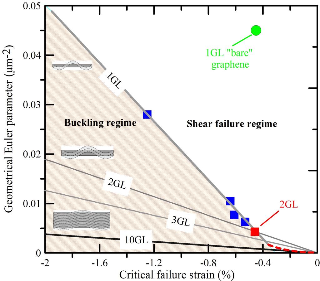
24 Graphene as a thin plate: critical buckling strain (1/2) The critical strain, ε c, for the buckling of a rectangular thin plate under uniaxial compression is given by the classical Euler formula: ε c π k κ w C 2 = 2 l: length (dimension parallel to strain) w: width m: number of half-waves to appear at the critical load κ: flexural rigidity, 3.18 GPa nm 3 =20 ev 1 C: tension rigidity, 340 GPa nm 1 k = mw l + 2 l mw k For a layer of atomic thickness in air, ε c 10-9 (1 nanostrain) l/w


25 Graphene as a thin plate: critical buckling strain (2/2) k w 2 = a ε + c b slope a = 0.03 μm -2 Euler regime applies for k> 0.05 μm -2 For freely suspended flake in air: For embedded flake: κ = ε κ GPa n m ~ 20 ev embedded c embedded k κ = 2 w = embedded C π GPa nm ~ 70 MeV,
26
27 Bending Stiffness, κ, for h=0.335 nm Specimen κ (ev) κ (Joules) Free-standing ~20 1 ~3*10-18 Embedded ~7 * 10 7 ~1*10-11 (70 MeV) 2 (10 pj) Simply-supported ~2 * 10 7 ~3*10-12 (20 MeV) 2 (3 pj) 3 1 Lee et al, Science, Frank et al, ACS Nano, Unpublished Data
28 Estimation of compression strength SLG Flake ε c (%) 1 σ c (GPa) 2 l (μm) w (μm) k k / w 2 (μm -2 ) F F F F ε c determined from the 2nd order polynomials as maxima 2 Assuming a modulus of 1 TPa and a linear relationship Typical compression strength of carbon fibres (microscale): 2-3 GPa
29 Moving across the length scales (the development of a universal stress sensor)


30 Graphite Carbon fibres are turbostratic : no regular stacking order Interplanar distance significantly larger than that in graphite Guigon & Oberlin, FST, 20, (1984)


31 Evolution of structure in CF
 that signed a 16-year in 2006 with Boeing")

32 BOEING 787 Dreamliner 80% CFC by volume and contains ~35 tons of carbon composite (23 tons of carbon fibre) Fuel consumption will be reduced by 20% than the comparable midsize 767 or Airbus A330 Toray industries (Japan) that signed a 16-year in 2006 with Boeing worth US $6 billion Demand for PAN (polyacrylonitrile)-based carbon fibre is growing 15 percent a year, driven now by the 787 At the end of 2003, Toray had capacity to produce 7,300 metric tons of carbon fiber products. By 2010, capacity has reached 13,900 metric tons

33 Europe s response: AIRBUS A350


34 TORAY Carbon Fibres

35
36 Carbon fibres vs. graphene (1/2) [tensile strength vs. modulus]
37 Carbon fibres vs. graphene (2/2) [strain-to-failure vs. modulus]
38 Carbon fibre: G peak strain sensitivity (1/2) 1580 G line HMS 0.0 fibres % 1.0% Pos(G) (cm -1 ) last fibre fracture Strain (%) Raman shift (cm -1 )
39 HM carbon fibre: G peak strain sensitivity (2/2) compression experimental data polynomial fit Wavenumber Shift (cm -1 ) tension Strain (%)

40 Flexible Raman Systems for Mechanical Measurements analyser λ/2 MTS To Portable spectrometer Confocal pinhole DPSS 532 nm (Internal laser source)
41 Strain distribution along a short fibre at +0.3% Strain (%) tension: 0.3% compression: -0.3% Norm. position along the fibre (-) Goutianos et al, Composites-Part A, 35/4, (2004) Goutianos, Int. J. Solids & Structures, 40/21, (2003)
 Goutianos et al, Composites-Part A, 35/4, 461-475 (2004) Goutianos, Int. J.")
42 Strain (%) Detection of failure processes tension: 0.8% compression: -0.8% Norm. position along the fibre (-) Goutianos et al, Composites-Part A, 35/4, (2004) Goutianos, Int. J. Solids & Structures, 40/21, (2003)


43 Master plot of ω ε vs. E for graphene and CF G G + line average θ in =0 θ out =0 (our experiments) G - line Frank et al, Nature Comms, 2011
 Graphene: The ultimate molecular")
 Frank et al, Nature Comms, DOI 10.")
44 Carbon fibres (microscale) Stress/ strain sensors Graphene (nanoscale) Graphene: The ultimate molecular strain/ stress sensor G σ T = ω0 (cm MPa ) Bennet (1976) Frank et al, Nature Comms, DOI , 2011
45 Applications Stress and/or strain sensors (non-destructive) Reinforcing agents (particularly for thin films) Nano-mechanical resonators
46 Conclusions Graphene: the stiffest, strongest and toughest material ever made (experiments on purely axial loading yet to be performed) The fundamental studies on graphene pave the way for understanding and improving other graphitic materials such as carbon fibres. A universal value for the rate of waveno shift per stress can be established for graphene: the invisible stress/ strain sensor.
47 Acknowledgements/ Collaborations Asst. Prof. K. Papagelis, Dr J. Parthenios, Dr D. Tassis, Ms. G. Tsoukleri (FORTH/ICE-HT, Univ. Patras, Greece) Dr O. Frank (J. Heyrovský Institute, Czech Republic) Dr. A. Ferrari (Univ. Cambridge, UK) Prof. A. Geim, Prof. K. Novoselov (Univ. Manchester, UK)
Deforming Single and Multilayer Graphenes in Tension and Compression
 Deforming Single and Multilayer Graphenes in Tension and Compression Costas Galio*s*, Georgia Tsoukleri, Konstan*nos Papagelis, John Parthenios Otakar Frank Kostya Novoselov FORTH/ICE- HT & Univ. Patras,
Supporting Information
 Supporting Information Failure Processes in Embedded Monolayer Graphene under Axial Compression Charalampos Androulidakis, Emmanuel N. Koukaras, Otakar Frank, Georgia Tsoukleri, Dimitris Sfyris, John Parthenios,
Subjecting a graphene monolayer to tension and compression
 Subjecting a graphene monolayer to tension and compression Georgia Tsoukleri 1,2, John Parthenios 1,2, Konstantinos Papagelis 3, Rashid Jalil 4, Andrea C. Ferrari 5, A. K. Geim 4, Kostya S. Novoselov 4
Experimentally derived axial stress- strain relations for twodimensional materials such as monolayer graphene
 Experimentally derived axial stress- strain relations for twodimensional materials such as monolayer graphene Ch. Androulidakis 1,2, G. Tsoukleri 2, N. Koutroumanis 2, G. Gkikas 2, P. Pappas 2, J. Parthenios
Intensity (a.u.) Intensity (a.u.) Raman Shift (cm -1 ) Oxygen plasma. 6 cm. 9 cm. 1mm. Single-layer graphene sheet. 10mm. 14 cm
 Intensity (a.u.) Raman Shift (cm -1 ) Oxygen plasma. 6 cm. 9 cm. 1mm. Single-layer graphene sheet. 10mm. 14 cm") Intensity (a.u.) Intensity (a.u.) a Oxygen plasma b 6 cm 1mm 10mm Single-layer graphene sheet 14 cm 9 cm Flipped Si/SiO 2 Patterned chip Plasma-cleaned glass slides c d After 1 sec normal Oxygen plasma
Intensity (a.u.) Intensity (a.u.) a Oxygen plasma b 6 cm 1mm 10mm Single-layer graphene sheet 14 cm 9 cm Flipped Si/SiO 2 Patterned chip Plasma-cleaned glass slides c d After 1 sec normal Oxygen plasma
Graphene-reinforced elastomers for demanding environments
 Graphene-reinforced elastomers for demanding environments Robert J Young, Ian A. Kinloch, Dimitrios G. Papageorgiou, J. Robert Innes and Suhao Li School of Materials and National Graphene Institute The
height trace of a 2L BN mechanically exfoliated on SiO 2 /Si with pre-fabricated micro-wells. Scale bar 2 µm.
 Supplementary Figure 1. Few-layer BN nanosheets. AFM image and the corresponding height trace of a 2L BN mechanically exfoliated on SiO 2 /Si with pre-fabricated micro-wells. Scale bar 2 µm. Supplementary
Supporting Information
 Supporting Information Thickness of suspended epitaxial graphene (SEG) resonators: Graphene thickness was estimated using an atomic force microscope (AFM) by going over the step edge from SiC to graphene.
Introduction to Engineering Materials ENGR2000. Dr. Coates
 Introduction to Engineering Materials ENGR2 Chapter 6: Mechanical Properties of Metals Dr. Coates 6.2 Concepts of Stress and Strain tension compression shear torsion Tension Tests The specimen is deformed
D : SOLID MECHANICS. Q. 1 Q. 9 carry one mark each. Q.1 Find the force (in kn) in the member BH of the truss shown.
 in the member BH of the truss shown.") D : SOLID MECHANICS Q. 1 Q. 9 carry one mark each. Q.1 Find the force (in kn) in the member BH of the truss shown. Q.2 Consider the forces of magnitude F acting on the sides of the regular hexagon having
D : SOLID MECHANICS Q. 1 Q. 9 carry one mark each. Q.1 Find the force (in kn) in the member BH of the truss shown. Q.2 Consider the forces of magnitude F acting on the sides of the regular hexagon having
PES Institute of Technology
 PES Institute of Technology Bangalore south campus, Bangalore-5460100 Department of Mechanical Engineering Faculty name : Madhu M Date: 29/06/2012 SEM : 3 rd A SEC Subject : MECHANICS OF MATERIALS Subject
MECHANICS OF 2D MATERIALS
 MECHANICS OF 2D MATERIALS Nicola Pugno Cambridge February 23 rd, 2015 2 Outline Stretching Stress Strain Stress-Strain curve Mechanical Properties Young s modulus Strength Ultimate strain Toughness modulus
QUESTION BANK SEMESTER: III SUBJECT NAME: MECHANICS OF SOLIDS
 QUESTION BANK SEMESTER: III SUBJECT NAME: MECHANICS OF SOLIDS UNIT 1- STRESS AND STRAIN PART A (2 Marks) 1. Define longitudinal strain and lateral strain. 2. State Hooke s law. 3. Define modular ratio,
Flexural properties of polymers
 A2 _EN BUDAPEST UNIVERSITY OF TECHNOLOGY AND ECONOMICS FACULTY OF MECHANICAL ENGINEERING DEPARTMENT OF POLYMER ENGINEERING Flexural properties of polymers BENDING TEST OF CHECK THE VALIDITY OF NOTE ON
ME 2570 MECHANICS OF MATERIALS
 ME 2570 MECHANICS OF MATERIALS Chapter III. Mechanical Properties of Materials 1 Tension and Compression Test The strength of a material depends on its ability to sustain a load without undue deformation
Massachusetts Institute of Technology Department of Aeronautics and Astronautics Cambridge, MA Problem Set 14
 Massachusetts Institute of Technology Department of Aeronautics and Astronautics Cambridge, MA 02139 16.01/16.02 Unified Engineering I, II Fall 2003 Problem Set 14 Name: Due Date: 12/9/03 F18 F19 F20 M19
ME 243. Mechanics of Solids
 ME 243 Mechanics of Solids Lecture 2: Stress and Strain Ahmad Shahedi Shakil Lecturer, Dept. of Mechanical Engg, BUET E-mail: sshakil@me.buet.ac.bd, shakil6791@gmail.com Website: teacher.buet.ac.bd/sshakil
PURE BENDING. If a simply supported beam carries two point loads of 10 kn as shown in the following figure, pure bending occurs at segment BC.
 BENDING STRESS The effect of a bending moment applied to a cross-section of a beam is to induce a state of stress across that section. These stresses are known as bending stresses and they act normally
EE C247B / ME C218 INTRODUCTION TO MEMS DESIGN SPRING 2014 C. Nguyen PROBLEM SET #4
 Issued: Wednesday, Mar. 5, 2014 PROBLEM SET #4 Due (at 9 a.m.): Tuesday Mar. 18, 2014, in the EE C247B HW box near 125 Cory. 1. Suppose you would like to fabricate the suspended cross beam structure below
EE C245 ME C218 Introduction to MEMS Design
 EE C245 ME C218 Introduction to MEMS Design Fall 2007 Prof. Clark T.-C. Nguyen Dept. of Electrical Engineering & Computer Sciences University of California at Berkeley Berkeley, CA 94720 Lecture 16: Energy
QUESTION BANK DEPARTMENT: CIVIL SEMESTER: III SUBJECT CODE: CE2201 SUBJECT NAME: MECHANICS OF SOLIDS UNIT 1- STRESS AND STRAIN PART A
 DEPARTMENT: CIVIL SUBJECT CODE: CE2201 QUESTION BANK SEMESTER: III SUBJECT NAME: MECHANICS OF SOLIDS UNIT 1- STRESS AND STRAIN PART A (2 Marks) 1. Define longitudinal strain and lateral strain. 2. State
Name :. Roll No. :... Invigilator s Signature :.. CS/B.TECH (CE-NEW)/SEM-3/CE-301/ SOLID MECHANICS
/SEM-3/CE-301/ SOLID MECHANICS") Name :. Roll No. :..... Invigilator s Signature :.. 2011 SOLID MECHANICS Time Allotted : 3 Hours Full Marks : 70 The figures in the margin indicate full marks. Candidates are required to give their answers
Name :. Roll No. :..... Invigilator s Signature :.. 2011 SOLID MECHANICS Time Allotted : 3 Hours Full Marks : 70 The figures in the margin indicate full marks. Candidates are required to give their answers
The science of elasticity
 The science of elasticity In 1676 Hooke realized that 1.Every kind of solid changes shape when a mechanical force acts on it. 2.It is this change of shape which enables the solid to supply the reaction
Stress-Strain Behavior
 Stress-Strain Behavior 6.3 A specimen of aluminum having a rectangular cross section 10 mm 1.7 mm (0.4 in. 0.5 in.) is pulled in tension with 35,500 N (8000 lb f ) force, producing only elastic deformation.
THE DETERMINATION OF FRACTURE STRENGTH FROM ULTIMATE TENSILE AND TRANSVERSE RUPTURE STRESSES
 Powder Metallurgy Progress, Vol.3 (003), No 3 119 THE DETERMINATION OF FRACTURE STRENGTH FROM ULTIMATE TENSILE AND TRANSVERSE RUPTURE STRESSES A.S. Wronski, A.Cias Abstract It is well-recognized that the
GEOSYNTHETICS ENGINEERING: IN THEORY AND PRACTICE
 GEOSYNTHETICS ENGINEERING: IN THEORY AND PRACTICE Prof. J. N. Mandal Department of Civil Engineering, IIT Bombay, Powai, Mumbai 400076, India. Tel.022-25767328 email: cejnm@civil.iitb.ac.in Module-13 LECTURE-
CIVIL DEPARTMENT MECHANICS OF STRUCTURES- ASSIGNMENT NO 1. Brach: CE YEAR:
 MECHANICS OF STRUCTURES- ASSIGNMENT NO 1 SEMESTER: V 1) Find the least moment of Inertia about the centroidal axes X-X and Y-Y of an unequal angle section 125 mm 75 mm 10 mm as shown in figure 2) Determine
Chapter 7. Highlights:
 Chapter 7 Highlights: 1. Understand the basic concepts of engineering stress and strain, yield strength, tensile strength, Young's(elastic) modulus, ductility, toughness, resilience, true stress and true
Mechanical Properties of Materials
 Mechanical Properties of Materials Strains Material Model Stresses Learning objectives Understand the qualitative and quantitative description of mechanical properties of materials. Learn the logic of
NORMAL STRESS. The simplest form of stress is normal stress/direct stress, which is the stress perpendicular to the surface on which it acts.
 NORMAL STRESS The simplest form of stress is normal stress/direct stress, which is the stress perpendicular to the surface on which it acts. σ = force/area = P/A where σ = the normal stress P = the centric
Tensile stress strain curves for different materials. Shows in figure below
 Tensile stress strain curves for different materials. Shows in figure below Furthermore, the modulus of elasticity of several materials effected by increasing temperature, as is shown in Figure Asst. Lecturer
Laboratory 4 Bending Test of Materials
 Department of Materials and Metallurgical Engineering Bangladesh University of Engineering Technology, Dhaka MME 222 Materials Testing Sessional.50 Credits Laboratory 4 Bending Test of Materials. Objective
Prediction of Young s Modulus of Graphene Sheets by the Finite Element Method
 American Journal of Mechanical Engineering, 15, Vol. 3, No. 6, 5-9 Available online at http://pubs.sciepub.com/ajme/3/6/14 Science and Education Publishing DOI:1.1691/ajme-3-6-14 Prediction of Young s
STRENGTH OF MATERIALS-I. Unit-1. Simple stresses and strains
 STRENGTH OF MATERIALS-I Unit-1 Simple stresses and strains 1. What is the Principle of surveying 2. Define Magnetic, True & Arbitrary Meridians. 3. Mention different types of chains 4. Differentiate between
arxiv: v1 [cond-mat.mtrl-sci] 21 Nov 2012
![arxiv: v1 [cond-mat.mtrl-sci] 21 Nov 2012](/thumbs/93/113836047.jpg "arxiv: v1 [cond-mat.mtrl-sci] 21 Nov 2012") In-plane force fields and elastic properties of graphene G. Kalosakas,, N. N. Lathiotakis, C. Galiotis,, and K. Papagelis, Materials Science Department, University of Patras, Rio GR-654, Greece ICE-HT/FORTH,
In-plane force fields and elastic properties of graphene G. Kalosakas,, N. N. Lathiotakis, C. Galiotis,, and K. Papagelis, Materials Science Department, University of Patras, Rio GR-654, Greece ICE-HT/FORTH,
Bending Load & Calibration Module
 Bending Load & Calibration Module Objectives After completing this module, students shall be able to: 1) Conduct laboratory work to validate beam bending stress equations. 2) Develop an understanding of
CHAPTER 3 THE EFFECTS OF FORCES ON MATERIALS
 CHAPTER THE EFFECTS OF FORCES ON MATERIALS EXERCISE 1, Page 50 1. A rectangular bar having a cross-sectional area of 80 mm has a tensile force of 0 kn applied to it. Determine the stress in the bar. Stress
Large scale growth and characterization of atomic hexagonal boron. nitride layers
 Supporting on-line material Large scale growth and characterization of atomic hexagonal boron nitride layers Li Song, Lijie Ci, Hao Lu, Pavel B. Sorokin, Chuanhong Jin, Jie Ni, Alexander G. Kvashnin, Dmitry
MECE 3321 MECHANICS OF SOLIDS CHAPTER 3
 MECE 3321 MECHANICS OF SOLIDS CHAPTER 3 Samantha Ramirez TENSION AND COMPRESSION TESTS Tension and compression tests are used primarily to determine the relationship between σ avg and ε avg in any material.
POST-PEAK BEHAVIOR OF FRP-JACKETED REINFORCED CONCRETE COLUMNS
 POST-PEAK BEHAVIOR OF FRP-JACKETED REINFORCED CONCRETE COLUMNS - Technical Paper - Tidarut JIRAWATTANASOMKUL *1, Dawei ZHANG *2 and Tamon UEDA *3 ABSTRACT The objective of this study is to propose a new
UNIVERSITY OF SASKATCHEWAN ME MECHANICS OF MATERIALS I FINAL EXAM DECEMBER 13, 2008 Professor A. Dolovich
 UNIVERSITY OF SASKATCHEWAN ME 313.3 MECHANICS OF MATERIALS I FINAL EXAM DECEMBER 13, 2008 Professor A. Dolovich A CLOSED BOOK EXAMINATION TIME: 3 HOURS For Marker s Use Only LAST NAME (printed): FIRST
2012 MECHANICS OF SOLIDS
 R10 SET - 1 II B.Tech II Semester, Regular Examinations, April 2012 MECHANICS OF SOLIDS (Com. to ME, AME, MM) Time: 3 hours Max. Marks: 75 Answer any FIVE Questions All Questions carry Equal Marks ~~~~~~~~~~~~~~~~~~~~~~
Outline. 4 Mechanical Sensors Introduction General Mechanical properties Piezoresistivity Piezoresistive Sensors Capacitive sensors Applications
 Sensor devices Outline 4 Mechanical Sensors Introduction General Mechanical properties Piezoresistivity Piezoresistive Sensors Capacitive sensors Applications Introduction Two Major classes of mechanical
Influence of residual stresses in the structural behavior of. tubular columns and arches. Nuno Rocha Cima Gomes
 October 2014 Influence of residual stresses in the structural behavior of Abstract tubular columns and arches Nuno Rocha Cima Gomes Instituto Superior Técnico, Universidade de Lisboa, Portugal Contact:
Supplementary Figures
 Fracture Strength (GPa) Supplementary Figures a b 10 R=0.88 mm 1 0.1 Gordon et al Zhu et al Tang et al im et al 5 7 6 4 This work 5 50 500 Si Nanowire Diameter (nm) Supplementary Figure 1: (a) TEM image
UNIT I SIMPLE STRESSES AND STRAINS
 Subject with Code : SM-1(15A01303) Year & Sem: II-B.Tech & I-Sem SIDDHARTH GROUP OF INSTITUTIONS :: PUTTUR Siddharth Nagar, Narayanavanam Road 517583 QUESTION BANK (DESCRIPTIVE) UNIT I SIMPLE STRESSES
December 10, PROBLEM NO points max.
 PROBLEM NO. 1 25 points max. PROBLEM NO. 2 25 points max. B 3A A C D A H k P L 2L Given: Consider the structure above that is made up of rod segments BC and DH, a spring of stiffness k and rigid connectors
MAAE 2202 A. Come to the PASS workshop with your mock exam complete. During the workshop you can work with other students to review your work.
 It is most beneficial to you to write this mock final exam UNDER EXAM CONDITIONS. This means: Complete the exam in 3 hours. Work on your own. Keep your textbook closed. Attempt every question. After the
CHAPTER 6: ULTIMATE LIMIT STATE
 CHAPTER 6: ULTIMATE LIMIT STATE 6.1 GENERAL It shall be in accordance with JSCE Standard Specification (Design), 6.1. The collapse mechanism in statically indeterminate structures shall not be considered.
Molecular Dynamics Simulation of Fracture of Graphene
 Molecular Dynamics Simulation of Fracture of Graphene Dewapriya M. A. N. 1, Rajapakse R. K. N. D. 1,*, Srikantha Phani A. 2 1 School of Engineering Science, Simon Fraser University, Burnaby, BC, Canada
MECHANICS LAB AM 317 EXP 3 BENDING STRESS IN A BEAM
 MECHANICS LAB AM 37 EXP 3 BENDING STRESS IN A BEAM I. OBJECTIVES I. To compare the experimentally determined stresses in a beam with those predicted from the simple beam theory (a.k.a. Euler-Bernoull beam
ME Final Exam. PROBLEM NO. 4 Part A (2 points max.) M (x) y. z (neutral axis) beam cross-sec+on. 20 kip ft. 0.2 ft. 10 ft. 0.1 ft.
 M (x) y. z (neutral axis) beam cross-sec+on. 20 kip ft. 0.2 ft. 10 ft. 0.1 ft.") ME 323 - Final Exam Name December 15, 2015 Instructor (circle) PROEM NO. 4 Part A (2 points max.) Krousgrill 11:30AM-12:20PM Ghosh 2:30-3:20PM Gonzalez 12:30-1:20PM Zhao 4:30-5:20PM M (x) y 20 kip ft 0.2
ME 323 - Final Exam Name December 15, 2015 Instructor (circle) PROEM NO. 4 Part A (2 points max.) Krousgrill 11:30AM-12:20PM Ghosh 2:30-3:20PM Gonzalez 12:30-1:20PM Zhao 4:30-5:20PM M (x) y 20 kip ft 0.2
Presented by: Civil Engineering Academy
 Presented by: Civil Engineering Academy Structural Design and Material Properties of Steel Presented by: Civil Engineering Academy Advantages 1. High strength per unit length resulting in smaller dead
CHAPTER THREE SYMMETRIC BENDING OF CIRCLE PLATES
 CHAPTER THREE SYMMETRIC BENDING OF CIRCLE PLATES * Governing equations in beam and plate bending ** Solution by superposition 1.1 From Beam Bending to Plate Bending 1.2 Governing Equations For Symmetric
MODELLING NON-LINEAR BEHAVIOUR OF STEEL FIBRE REINFORCED CONCRETE
 6th RILEM Symposium on Fibre-Reinforced Concretes (FRC) - BEFIB - September, Varenna, Italy MODELLING NON-LINEAR BEHAVIOUR OF STEEL FIBRE REINFORCED CONCRETE W. A. Elsaigh, J. M. Robberts and E.P. Kearsley
Mechanical Properties
 Mechanical Properties Elastic deformation Plastic deformation Fracture I. Elastic Deformation S s u s y e u e T I II III e For a typical ductile metal: I. Elastic deformation II. Stable plastic deformation
An orthotropic damage model for crash simulation of composites
 High Performance Structures and Materials III 511 An orthotropic damage model for crash simulation of composites W. Wang 1, F. H. M. Swartjes 1 & M. D. Gan 1 BU Automotive Centre of Lightweight Structures
Effect of Specimen Dimensions on Flexural Modulus in a 3-Point Bending Test
 Effect of Specimen Dimensions on Flexural Modulus in a 3-Point Bending Test M. Praveen Kumar 1 and V. Balakrishna Murthy 2* 1 Mechanical Engineering Department, P.V.P. Siddhartha Institute of Technology,
Mechanics of Solids. Mechanics Of Solids. Suraj kr. Ray Department of Civil Engineering
 Mechanics Of Solids Suraj kr. Ray (surajjj2445@gmail.com) Department of Civil Engineering 1 Mechanics of Solids is a branch of applied mechanics that deals with the behaviour of solid bodies subjected
Modelling the nonlinear shear stress-strain response of glass fibrereinforced composites. Part II: Model development and finite element simulations
 Modelling the nonlinear shear stress-strain response of glass fibrereinforced composites. Part II: Model development and finite element simulations W. Van Paepegem *, I. De Baere and J. Degrieck Ghent
Engineering Design for Ocean and Ice Environments Engineering Sea Ice Engineering
 Engineering 867 - Design for Ocean and Ice Environments Engineering 9096 - Sea Ice Engineering MID-TERM EXAMINATION With Solutions Date: Fri., Feb. 6, 009 Time: 1:00-1:50 pm Professor: Dr. C. Daley Answer
FLEXURAL MODELLING OF STRAIN SOFTENING AND STRAIN HARDENING FIBER REINFORCED CONCRETE
 Proceedings, Pro. 53, S.A.R.L., Cachan, France, pp.55-6, 7. FLEXURAL MODELLING OF STRAIN SOFTENING AND STRAIN HARDENING FIBER REINFORCED CONCRETE Chote Soranakom and Barzin Mobasher Department of Civil
Chapter 6: Mechanical Properties of Metals. Dr. Feras Fraige
 Chapter 6: Mechanical Properties of Metals Dr. Feras Fraige Stress and Strain Tension Compression Shear Torsion Elastic deformation Plastic Deformation Yield Strength Tensile Strength Ductility Toughness
Finite element modelling of infinitely wide Angle-ply FRP. laminates
 www.ijaser.com 2012 by the authors Licensee IJASER- Under Creative Commons License 3.0 editorial@ijaser.com Research article ISSN 2277 9442 Finite element modelling of infinitely wide Angle-ply FRP laminates
CHEM-C2410: Materials Science from Microstructures to Properties Composites: basic principles
 CHEM-C2410: Materials Science from Microstructures to Properties Composites: basic principles Mark Hughes 14 th March 2017 Today s learning outcomes To understand the role of reinforcement, matrix and
Module III - Macro-mechanics of Lamina. Lecture 23. Macro-Mechanics of Lamina
 Module III - Macro-mechanics of Lamina Lecture 23 Macro-Mechanics of Lamina For better understanding of the macromechanics of lamina, the knowledge of the material properties in essential. Therefore, the
Civil Engineering Design (1) Design of Reinforced Concrete Columns 2006/7
 Design of Reinforced Concrete Columns 2006/7") Civil Engineering Design (1) Design of Reinforced Concrete Columns 2006/7 Dr. Colin Caprani, Chartered Engineer 1 Contents 1. Introduction... 3 1.1 Background... 3 1.2 Failure Modes... 5 1.3 Design Aspects...
Civil Engineering Design (1) Design of Reinforced Concrete Columns 2006/7 Dr. Colin Caprani, Chartered Engineer 1 Contents 1. Introduction... 3 1.1 Background... 3 1.2 Failure Modes... 5 1.3 Design Aspects...
MOLECULAR SIMULATION FOR PREDICTING MECHANICAL STRENGTH OF 3-D JUNCTIONED CARBON NANOSTRUCTURES
 ECCM16-16 TH EUROPEAN CONFERENCE ON COMPOSITE MATERIALS, Seville, Spain, 22-26 June 214 MOLECULAR SIMULATION FOR PREDICTING MECHANICAL STRENGTH OF 3-D JUNCTIONED CARBON NANOSTRUCTURES S. Sihn a,b*, V.
3. BEAMS: STRAIN, STRESS, DEFLECTIONS
 3. BEAMS: STRAIN, STRESS, DEFLECTIONS The beam, or flexural member, is frequently encountered in structures and machines, and its elementary stress analysis constitutes one of the more interesting facets
20. Rheology & Linear Elasticity
 I Main Topics A Rheology: Macroscopic deformation behavior B Linear elasticity for homogeneous isotropic materials 10/29/18 GG303 1 Viscous (fluid) Behavior http://manoa.hawaii.edu/graduate/content/slide-lava
INFLUENCE OF FLANGE STIFFNESS ON DUCTILITY BEHAVIOUR OF PLATE GIRDER
 International Journal of Civil Structural 6 Environmental And Infrastructure Engineering Research Vol.1, Issue.1 (2011) 1-15 TJPRC Pvt. Ltd.,. INFLUENCE OF FLANGE STIFFNESS ON DUCTILITY BEHAVIOUR OF PLATE
Lecture 15 Strain and stress in beams
 Spring, 2019 ME 323 Mechanics of Materials Lecture 15 Strain and stress in beams Reading assignment: 6.1 6.2 News: Instructor: Prof. Marcial Gonzalez Last modified: 1/6/19 9:42:38 PM Beam theory (@ ME
Experiment Five (5) Principal of Stress and Strain
 Principal of Stress and Strain") Experiment Five (5) Principal of Stress and Strain Introduction Objective: To determine principal stresses and strains in a beam made of aluminum and loaded as a cantilever, and compare them with theoretical
Experiment Five (5) Principal of Stress and Strain Introduction Objective: To determine principal stresses and strains in a beam made of aluminum and loaded as a cantilever, and compare them with theoretical
Strain Measurement. Prof. Yu Qiao. Department of Structural Engineering, UCSD. Strain Measurement
 Strain Measurement Prof. Yu Qiao Department of Structural Engineering, UCSD Strain Measurement The design of load-carrying components for machines and structures requires information about the distribution
Revealing bending and force in a soft body through a plant root inspired. approach. Lucia Beccai 1* Piaggio 34, Pontedera (Italy)
") Revealing bending and force in a soft body through a plant root inspired approach Chiara Lucarotti 1,2, Massimo Totaro 1, Ali Sadeghi 1, Barbara Mazzolai 1, Lucia Beccai 1* 1 Center for Micro-BioRobotics
Revealing bending and force in a soft body through a plant root inspired approach Chiara Lucarotti 1,2, Massimo Totaro 1, Ali Sadeghi 1, Barbara Mazzolai 1, Lucia Beccai 1* 1 Center for Micro-BioRobotics
Open-hole compressive strength prediction of CFRP composite laminates
 Open-hole compressive strength prediction of CFRP composite laminates O. İnal 1, A. Ataş 2,* 1 Department of Mechanical Engineering, Balikesir University, Balikesir, 10145, Turkey, inal@balikesir.edu.tr
Mechanical Behavior of Circular Composite Springs with Extended Flat Contact Surfaces
 Mechanical Behavior of Circular Composite Springs with Extended Flat Contact Surfaces Ping-Cheung Tse epartment of Mechanical Engineering, The Hong Kong Polytechnic University, Hunghom, Kowloon, Hong Kong
Experimental investigation on monotonic performance of steel curved knee braces for weld-free beam-to-column connections
 Experimental investigation on monotonic performance of steel curved knee braces for weld-free beam-to-column connections *Zeyu Zhou 1) Bo Ye 2) and Yiyi Chen 3) 1), 2), 3) State Key Laboratory of Disaster
DAMAGE MECHANICS MODEL FOR OFF-AXIS FATIGUE BEHAVIOR OF UNIDIRECTIONAL CARBON FIBER-REINFORCED COMPOSITES AT ROOM AND HIGH TEMPERATURES
 DAMAGE MECHANICS MODEL FOR OFF-AXIS FATIGUE BEHAVIOR OF UNIDIRECTIONAL CARBON FIBER-REINFORCED COMPOSITES AT ROOM AND HIGH TEMPERATURES M. Kawai Institute of Engineering Mechanics University of Tsukuba,
Outline. Tensile-Test Specimen and Machine. Stress-Strain Curve. Review of Mechanical Properties. Mechanical Behaviour
 Tensile-Test Specimen and Machine Review of Mechanical Properties Outline Tensile test True stress - true strain (flow curve) mechanical properties: - Resilience - Ductility - Toughness - Hardness A standard
Multi Disciplinary Delamination Studies In Frp Composites Using 3d Finite Element Analysis Mohan Rentala
 Multi Disciplinary Delamination Studies In Frp Composites Using 3d Finite Element Analysis Mohan Rentala Abstract: FRP laminated composites have been extensively used in Aerospace and allied industries
FIS Specifications for Flex Poles (Edition May 2008) Original Text: German
 Original Text: German") FIS Specifications for Flex Poles (Edition May 2008) Original Text: German 1 Field of Application and Basic Information The following FIS specifications for flex poles are intended to ensure that flex
FIS Specifications for Flex Poles (Edition May 2008) Original Text: German 1 Field of Application and Basic Information The following FIS specifications for flex poles are intended to ensure that flex
MECHANICS OF MATERIALS
 CHATR Stress MCHANICS OF MATRIALS and Strain Axial Loading Stress & Strain: Axial Loading Suitability of a structure or machine may depend on the deformations in the structure as well as the stresses induced
Fig. 1. Different locus of failure and crack trajectories observed in mode I testing of adhesively bonded double cantilever beam (DCB) specimens.
 specimens.") a). Cohesive Failure b). Interfacial Failure c). Oscillatory Failure d). Alternating Failure Fig. 1. Different locus of failure and crack trajectories observed in mode I testing of adhesively bonded double
a). Cohesive Failure b). Interfacial Failure c). Oscillatory Failure d). Alternating Failure Fig. 1. Different locus of failure and crack trajectories observed in mode I testing of adhesively bonded double
KINGS COLLEGE OF ENGINEERING DEPARTMENT OF MECHANICAL ENGINEERING QUESTION BANK. Subject code/name: ME2254/STRENGTH OF MATERIALS Year/Sem:II / IV
 KINGS COLLEGE OF ENGINEERING DEPARTMENT OF MECHANICAL ENGINEERING QUESTION BANK Subject code/name: ME2254/STRENGTH OF MATERIALS Year/Sem:II / IV UNIT I STRESS, STRAIN DEFORMATION OF SOLIDS PART A (2 MARKS)
An integrated approach to the design of high performance carbon fibre reinforced risers - from micro to macro - scale
 An integrated approach to the design of high performance carbon fibre reinforced risers - from micro to macro - scale Angelos Mintzas 1, Steve Hatton 1, Sarinova Simandjuntak 2, Andrew Little 2, Zhongyi
COURSE TITLE : APPLIED MECHANICS & STRENGTH OF MATERIALS COURSE CODE : 4017 COURSE CATEGORY : A PERIODS/WEEK : 6 PERIODS/ SEMESTER : 108 CREDITS : 5
 COURSE TITLE : APPLIED MECHANICS & STRENGTH OF MATERIALS COURSE CODE : 4017 COURSE CATEGORY : A PERIODS/WEEK : 6 PERIODS/ SEMESTER : 108 CREDITS : 5 TIME SCHEDULE MODULE TOPICS PERIODS 1 Simple stresses
FLEXURAL DESIGN OF STRAIN HARDENING CEMENT COMPOSITES
 BEFIB01 Fibre reinforced conete Joaquim Barros et al. (Eds) UM, Guimarães, 01 FLEXURAL DESIGN OF STRAIN HARDENING CEMENT COMPOSITES Barzin Mobasher*, Christopher Barsby* * School of Sustainable Engineering
Deflections and Strains in Cracked Shafts due to Rotating Loads: A Numerical and Experimental Analysis
 Rotating Machinery, 10(4): 283 291, 2004 Copyright c Taylor & Francis Inc. ISSN: 1023-621X print / 1542-3034 online DOI: 10.1080/10236210490447728 Deflections and Strains in Cracked Shafts due to Rotating
The objective of this experiment is to investigate the behavior of steel specimen under a tensile test and to determine it's properties.
 Objective: The objective of this experiment is to investigate the behavior of steel specimen under a tensile test and to determine it's properties. Introduction: Mechanical testing plays an important role
SHEAR CAPACITY OF REINFORCED CONCRETE COLUMNS RETROFITTED WITH VERY FLEXIBLE FIBER REINFORCED POLYMER WITH VERY LOW YOUNG S MODULUS
 SHEAR CAPACITY OF REINFORCED CONCRETE COLUMNS RETROFITTED WITH VERY FLEXILE FIER REINFORCED POLYMER WITH VERY LOW YOUNG S MODULUS Hu Shaoqing Supervisor: Susumu KONO ** MEE8165 ASTRACT FRP with low Young
ANALYSIS OF YARN BENDING BEHAVIOUR
 ANALYSIS OF YARN BENDING BEHAVIOUR B. Cornelissen, R. Akkerman Faculty of Engineering Technology, University of Twente Drienerlolaan 5, P.O. Box 217; 7500 AE Enschede, the Netherlands b.cornelissen@utwente.nl
ε t increases from the compressioncontrolled Figure 9.15: Adjusted interaction diagram
 CHAPTER NINE COLUMNS 4 b. The modified axial strength in compression is reduced to account for accidental eccentricity. The magnitude of axial force evaluated in step (a) is multiplied by 0.80 in case
Shear Properties and Wrinkling Behaviors of Finite Sized Graphene
 Shear Properties and Wrinkling Behaviors of Finite Sized Graphene Kyoungmin Min, Namjung Kim and Ravi Bhadauria May 10, 2010 Abstract In this project, we investigate the shear properties of finite sized
Free Vibrations of Carbon Nanotubes with Defects
 Mechanics and Mechanical Engineering Vol. 17, No. 2 (2013) 157 166 c Lodz University of Technology Free Vibrations of Carbon Nanotubes with Defects Aleksander Muc Aleksander Banaś Ma lgorzata Chwa l Institute
3.032 Problem Set 2 Solutions Fall 2007 Due: Start of Lecture,
 3.032 Problem Set 2 Solutions Fall 2007 Due: Start of Lecture, 09.21.07 1. In the beam considered in PS1, steel beams carried the distributed weight of the rooms above. To reduce stress on the beam, it
Chapter 5 Structural Elements: The truss & beam elements
 Institute of Structural Engineering Page 1 Chapter 5 Structural Elements: The truss & beam elements Institute of Structural Engineering Page 2 Chapter Goals Learn how to formulate the Finite Element Equations
IDENTIFICATION OF THE ELASTIC PROPERTIES ON COMPOSITE MATERIALS AS A FUNCTION OF TEMPERATURE
 IDENTIFICATION OF THE ELASTIC PROPERTIES ON COMPOSITE MATERIALS AS A FUNCTION OF TEMPERATURE Hugo Sol, hugos@vub.ac.be Massimo Bottiglieri, Massimo.Bottiglieri@vub.ac.be Department Mechanics of Materials
A HIGHER-ORDER BEAM THEORY FOR COMPOSITE BOX BEAMS
 A HIGHER-ORDER BEAM THEORY FOR COMPOSITE BOX BEAMS A. Kroker, W. Becker TU Darmstadt, Department of Mechanical Engineering, Chair of Structural Mechanics Hochschulstr. 1, D-64289 Darmstadt, Germany kroker@mechanik.tu-darmstadt.de,
In Situ Ultrasonic NDT of Fracture and Fatigue in Composites
 ECNDT 26 - Mo.2.6.5 In Situ Ultrasonic NDT of Fracture and Fatigue in Composites I. SOLODOV, K. PFLEIDERER, and G. BUSSE Institute for Polymer Testing and Polymer Science (IKP), Non-destructive Testing