Parameter Study and Coupled S-Parameter Calculations of Superconducting RF Cavities
|
|
|
- Leona Jennings
- 6 years ago
- Views:
Transcription


1 Parameter Study and Coupled S-Parameter Calculations of Superconducting RF Cavities Tomasz Galek, Thomas Flisgen, Korinna Brackebusch, Kai Papke and Ursula van Rienen CST European User Conference , Mannheim, Germany
2 Outline Introduction Motivation Simulation approach Parameter studies on HOM geometrical dependencies Geometrical Perturbation of Cavities Methods for computation of beam excited HOM port signals Acknowledgments 2
3 Introduction RF-Cavities, HOMs and Wakefields 3
. *R.")
4 RF-Fields and Cavities to accelerate Charged Particles Superconducting TESLA 1.3 GHz 9-cell cavity.* Input coupler to excite pimode in cavity Electric field of resonant pi mode of 3.9 GHz cavity (phase shift of π from cell to cell). *R. Wanzenberg: Monopole, Dipole and Quadrupole Passbands of the TESLA 9-cell Cavity, TESLA-Report
5 Flip Book: Interaction Pi mode and Charged Particle* Negative test charge sees a force in longitudinal (+z) - direction due to and gains energy. *qualitative consideration 5
6 Flip Book: Interaction Pi mode and Charged Particle* Negative test charge sees a force in longitudinal (+z) - direction due to and gains energy. *qualitative consideration 6
7 Flip Book: Interaction Pi mode and Charged Particle* Negative test charge sees a force in longitudinal (+z) - direction due to and gains energy. *qualitative consideration 7
8 Flip Book: Interaction Pi mode and Charged Particle* Negative test charge sees a force in longitudinal (+z) - direction due to and gains energy. *qualitative consideration 8
9 Flip Book: Interaction Pi mode and Charged Particle* Negative test charge sees a force in longitudinal (+z) - direction due to and gains energy. *qualitative consideration 9
10 Flip Book: Interaction Pi mode and Charged Particle* Negative test charge sees a force in longitudinal (+z) - direction due to and gains energy. *qualitative consideration 10
11 Flip Book: Interaction Pi mode and Charged Particle* Negative test charge sees a force in longitudinal (+z) - direction due to and gains energy. *qualitative consideration 11
12 Flip Book: Interaction Pi mode and Charged Particle* Negative test charge sees a force in longitudinal (+z) - direction due to and gains energy. *qualitative consideration 12
13 Flip Book: Interaction Pi mode and Charged Particle* Negative test charge sees a force in longitudinal (+z) - direction due to and gains energy. *qualitative consideration 13
14 Flip Book: Interaction Pi mode and Charged Particle* Negative test charge sees a force in longitudinal (+z) - direction due to and gains energy. *qualitative consideration 14
15 Flip Book: Interaction Pi mode and Charged Particle* Negative test charge sees a force in longitudinal (+z) - direction due to and gains energy. *qualitative consideration 15
16 Flip Book: Interaction Pi mode and Charged Particle* Negative test charge sees a force in longitudinal (+z) - direction due to and gains energy. *qualitative consideration 16
17 Flip Book: Interaction Pi mode and Charged Particle* Negative test charge sees a force in longitudinal (+z) - direction due to and gains energy. *qualitative consideration 17
18 Flip Book: Interaction Pi mode and Charged Particle* Negative test charge sees a force in longitudinal (+z) - direction due to and gains energy. *qualitative consideration 18
19 Flip Book: Interaction Pi mode and Charged Particle* Negative test charge sees a force in longitudinal (+z) - direction due to and gains energy. *qualitative consideration 19
20 Flip Book: Interaction Pi mode and Charged Particle* Negative test charge sees a force in longitudinal (+z) - direction due to and gains energy. *qualitative consideration 20
21 Flip Book: Interaction Pi mode and Charged Particle* Negative test charge sees a force in longitudinal (+z) - direction due to and gains energy. *qualitative consideration 21
22 Flip Book: Interaction Pi mode and Charged Particle* Negative test charge sees a force in longitudinal (+z) - direction due to and gains energy. *qualitative consideration 22
23 Flip Book: Interaction Pi mode and Charged Particle* Negative test charge sees a force in longitudinal (+z) - direction due to and gains energy. *qualitative consideration 23
24 Flip Book: Interaction Pi mode and Charged Particle* Negative test charge sees a force in longitudinal (+z) - direction due to and gains energy. *qualitative consideration 24
25 Flip Book: Interaction Pi mode and Charged Particle* Negative test charge sees a force in longitudinal (+z) - direction due to and gains energy. *qualitative consideration 25
26 Flip Book: Interaction Pi mode and Charged Particle* Negative test charge sees a force in longitudinal (+z) - direction due to and gains energy. *qualitative consideration 26
27 Flip Book: Interaction Pi mode and Charged Particle* Negative test charge sees a force in longitudinal (+z) - direction due to and gains energy. *qualitative consideration 27
28 Flip Book: Interaction Pi mode and Charged Particle* Negative test charge sees a force in longitudinal (+z) - direction due to and gains energy. *qualitative consideration 28
29 Flip Book: Interaction Pi mode and Charged Particle* Negative test charge sees a force in longitudinal (+z) - direction due to and gains energy. *qualitative consideration 29
30 Flip Book: Interaction Pi mode and Charged Particle* Negative test charge sees a force in longitudinal (+z) - direction due to and gains energy. *qualitative consideration 30
31 Flip Book: Interaction Pi mode and Charged Particle* Negative test charge sees a force in longitudinal (+z) - direction due to and gains energy. *qualitative consideration 31
32 Flip Book: Interaction Pi mode and Charged Particle* Negative test charge sees a force in longitudinal (+z) - direction due to and gains energy. *qualitative consideration 32
33 Flip Book: Interaction Pi mode and Charged Particle* Negative test charge sees a force in longitudinal (+z) - direction due to and gains energy. *qualitative consideration 33
34 Flip Book: Interaction Pi mode and Charged Particle* Negative test charge sees a force in longitudinal (+z) - direction due to and gains energy. *qualitative consideration 34
 - direction due to and gains energy.")
35 Flip Book: Interaction Pi mode and Charged Particle* Negative test charge sees a force in longitudinal (+z) - direction due to and gains energy. *qualitative consideration 35
36 Flip Book: Interaction Pi mode and Charged Particle* Negative test charge sees a force in longitudinal (+z) - direction due to and gains energy. *qualitative consideration 36
37 Flip Book: Interaction Pi mode and Charged Particle* Negative test charge sees a force in longitudinal (+z) - direction due to and gains energy. *qualitative consideration 37
38 Flip Book: Interaction Pi mode and Charged Particle* Negative test charge sees a force in longitudinal (+z) - direction due to and gains energy. *qualitative consideration 38
39 Flip Book: Interaction Pi mode and Charged Particle* Negative test charge sees a force in longitudinal (+z) - direction due to and gains energy. *qualitative consideration 39
40 Flip Book: Interaction Pi mode and Charged Particle* Negative test charge sees a force in longitudinal (+z) - direction due to and gains energy. *qualitative consideration 40
41 Flip Book: Interaction Pi mode and Charged Particle* Negative test charge sees a force in longitudinal (+z) - direction due to and gains energy. *qualitative consideration 41


42 Total Energy gained by Charged Particle passing Cavity, where is the energy gained by particle, is the charge of particle and the electric field, seen by particle. 42

43 Modes of Cavity Beside π mode the cavity has an infinite set of other resonant Higher Order Modes: of arbritary chosen HOMs Charged particles travelling through cavity are able to excite Higher Order Modes! 43
: It is possible to decompose the wakefields as HOMs*, where is the wakefield distribution, a time dependent weighting factor and E-field distribution of HOM. *T. Weiland, R.")
44 Beam Excited Fields or Wakefields and HOMs Bunch of charged particles exciting wakefields (abs. value of E-Field): It is possible to decompose the wakefields as HOMs*, where is the wakefield distribution, a time dependent weighting factor and E-field distribution of HOM. *T. Weiland, R. Wanzenberg, "Wakefields and Impedances", Proceedings of the CAT-CERN Accelerator School (CCAS), pp ,
45 How long do the Fields stay in Resonator? Once the charged particle(s) have left the structure, the HOMs decay exponentially:, with for, where is time particles need to pass cavity, a constant amplitude, a constant phase shift, resonant frequency of mode and the quality factor of mode. Due to small losses in cavity, Q-factor is large and HOMs decay slowly. HOMs interact with following particles passing structure and need to be damped. 45
. HOM couplers connected to matched loads on high temperature level. Ideally they do not couple to π mode.")
46 Couplers to damp HOMs HOM couplers power coupler HOM couplers dissipate energy of HOMs (in fact they lower Q-factor of HOMs). HOM couplers connected to matched loads on high temperature level. Ideally they do not couple to π mode. 46
47 Motivation 47
48 Motivation: Parasitical use of HOM couplers: Diagnostic System based on HOM port signals* of ACC39 mounted in FLASH String of cavities in ACC39** Information about e.g.: EDP Transversal momentum and offset of bunch Perturbances of cavity Total charge of bunch *Principle according to S. Molloy et al.: High precision superconducting cavity diagnostics with higher order mode measurements", Phys. Rev. Spec. Top. Accel. Beams 9 (2006) , **Picture taken from: E. Vogel et al.: Status of the 3rd harmonic systems for FLASH and XFEL in summer 2008, Proc. LINAC


49 Motivation: Parasitical use of HOM couplers: Diagnostic System based on HOM port signals* of ACC39 mounted in FLASH String of cavities in ACC39** Information about e.g.: Beside of measurements simulations are needed for a Transversal momentum and offset of bunch better understanding of the beam excited HOM port signals EDP Perturbances of cavity Total charge of bunch *Principle according to S. Molloy et al.: High precision superconducting cavity diagnostics with higher order mode measurements", Phys. Rev. Spec. Top. Accel. Beams 9 (2006) , **Picture taken from: E. Vogel et al.: Status of the 3rd harmonic systems for FLASH and XFEL in summer 2008, Proc. LINAC
50 Simulation Approach 50
51 Numerical Treatment of RF Structure Structure * Elements of Structure Numerical Treatment of Elements Concatenation Some advantages of decomposition: Numerical treatment of sections is less demanding than treatment of entire structure. Identical sections need to be treated only once. Efficient to simulate influence of pertubation of a segment on full structure. *Picture taken from: E. Vogel et al.: Status of the 3rd harmonic systems for FLASH and XFEL in summer 2008, Proc. LINAC

52 20 log S12(ω) Sampled S-matrices Topology information Example Coupled S-Parameter Calculation* Calculation of Segment s S-matrices using CST MWS Direct Computation CSC CSC frequency / GHz *H.-W. Glock, K. Rothemund, U. van Rienen: "CSC - A System for Coupled S-Parameter Calculations", TESLA-Report

53 Model Validation ACC39 C1 C2 C3 C4 Measurement Simulation frequency / Hz Need to consider the whole string instead of individual cavities since HOMs can propagate through entire string 53
54 Parameter Studies on HOM Geometrical Dependencies using CSC 54


55 Third Harmonic Cavity composed of Single Cells midcell inverse length endcell Endcell Midcell 3,090,528 hexahedral cells 8 modes excited on port P1 20 modes excited on port P2 computing time*: 3h 5 min 3,130,608 hexahedral cells 20 modes excited on both ports computing time*: 6h 18 min *using CST MWS FR solver 55

56 S21(TE11) / db Comparison: Direct vs. Coupling Direct computation with N=8,12 Mio hexahedral mesh cells, computing time FR solver: T=11h CSC coupling of mid- and end cell elements (only TE11 mode is considered), computing time CSC: couple of seconds Parasitarical TM01 passband of direct computation frequency / Hz 56
57 Perturbation of a Single Cell in the Resonator Length of mid cup is mm instead of mm! Source: T. Khabibouline et al.: Higher Order Modes of a 3rd Harmonic Cavity with an Increased End-cup Iris. TESLA-FEL , May
58 S21(TE11) / db Influence of Pertubed Cell Position on HOM (1/4) perturbed cell frequency / Hz 58
59 S21(TE11) / db Influence of Pertubed Cell Position on HOM (2/4) perturbed cell frequency / Hz 59
60 S21(TE11) / db Influence of Pertubed Cell Position on HOM (3/4) perturbed cell frequency / Hz 60
61 S21(TE11) / db Influence of Pertubed Cell Position on HOM (4/4) perturbed cell frequency / Hz 61
62 S21(TE11) / db Influence of Pertubed Cell Position on HOM (4/4) perturbed cell No straight forward determinism to allocate perturbed cell in the chain based on HOM spectrum Strong dependency of second dipole passband on position of perturbed cell frequency / Hz 62
63 20 log S12(ω) Influence Input Coupler Reflection on HOM Spectrum Complex Reflection Factor at Input Coupler Im Transmission from left to right HOM coupler Re Reference Sweep frequency / Hz 63
64 20 log S12(ω) Influence Input Coupler Reflection on HOM Spectrum Complex Reflection Factor at Input Coupler Im Transmission from left to right HOM coupler Re Strong dependency of second dipole passband on reflection factor at input coupler Reference Sweep frequency / Hz 64

65 Cornell Design HOM damping design for BERLINPRO HOM waveguide couplers Input coupler 65
66 BERLINPRO : Design of the waveguide HOM couplers Identifying of HOMs propagating in 3 cavities chains HOMs Q loaded estimation using pole fitting * * H.-W. Glock, T. Galek, G. Pöplau, U. van Rienen, HOM Spectrum and Q-Factor estimations of the High-Beta CERN-SPL-Cavities, Proceedings of 1st International Particle Accelerator Con-ference (IPAC 2010), Kyoto, Japan, May 23 28, 2010 (2010): pp
67 Geometrical Perturbation of Cavities 67
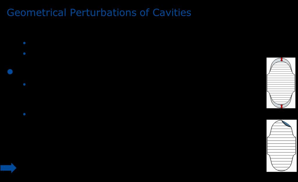
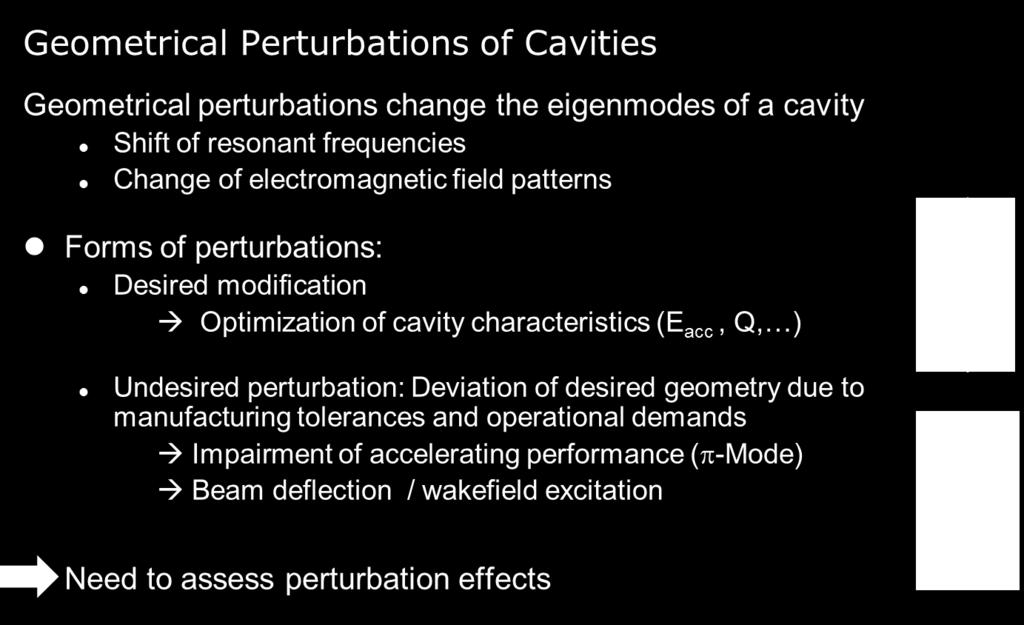
68 68
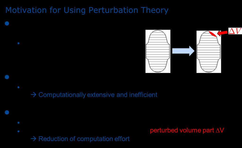
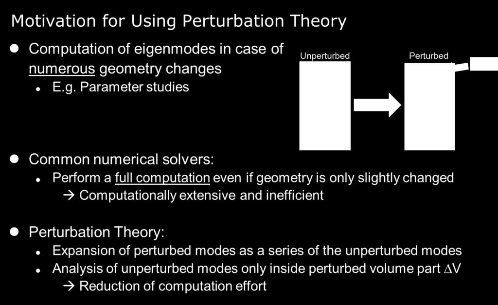
69 69
70 70
71 Development of Methods to Compute Beam Excited HOM Port Signals at ACC39 71
72 Beam Excited Fields in ACC39 For computation of HOM port signals of ACC39 the entire chain of cavities needs to be considered. Costly to discretize entire structure, but ACC39 is made of identical sub-structures (at least in ideal case). Efficient to compute (HOM) port signal contributions of substructures and concatenate those. Additional feature: sections with constant cross section can be described analytically (if lossless). Generalized CSC: Coupled Time Domain Computations* *T. Flisgen, H.-W. Glock and U. van Rienen: A Concatenation Scheme for the Computation of Beam Excited Higher Order Mode Port Signals, Proceedings of IPAC2011, San Sebastián, Spain 72

73 Decomposition of Structure and Concatenation Direct computation of transient beam excited port signals* using CST Particle Studio Elementwise computation of transient beam excited port signals* using CST Particle Studio Obj. 1 Obj. 2? CTC *scattered in TM01 mode 73
74 CTC - Proof of Principle Direct computation CTC (S-parameter computed in an interval f = 1GHz...8GHz) Direct computation * *signals filtered with low pass filter fc = 10 GHz Bunch properties: 74


75 CTC - Proof of Principle Direct computation CTC (S-parameter computed in an interval f = 1GHz...8GHz) Direct computation * Good agreement between direct computation and element-wise computation *signals filtered with low pass filter fc = 10 GHz Bunch properties: 75

 Solver *Bachelor project of")
76 Topology information Workflow for State Space Coupling* Solve real eigenproblem for each segment Coupling Scattering formulation of full structure in time domain* Impedance formulation of full structure in time domain *transient response available using Ordinary Differential Equations (ODE) Solver *Bachelor project of Johann Heller 76


77 Validation Example for State Space Coupling* Section I and III: Beampipe with antenna tip 50 3-D eigenmodes computed for modal expansion Section II: Simplified third harmonic cavity with three cells 50 3-D eigenmodes computed for modal expansion *Bachelor project of Johann Heller 77
78 Comparison Direct vs. State Space Coupling* *Plot courtesy of Johann Heller Considered pipe modes for expansion: 1. TE11 Pol. 1 fco = GHz 2. TE11 Pol. 2 fco = GHz 3. TM01 fco = GHz 4. TE21 Pol. 1 fco = GHz 5. TE21 Pol. 2 fco = GHz 6. TE01 fco = GHz 7. TM11 Pol. 1 fco = GHz 8. TM11 Pol. 2 fco = GHz frequency / GHz 78


79 Comparison Direct vs. State Space Coupling* frequency / GHz Considered pipe modes for expansion: 1. TE11 Pol. 1 fco = GHz 2. TE11 Pol. 2 fco = GHz 3. TM01 fco = GHz 4. TE21 Pol. 1 fco = GHz 5. TE21 Pol. 2 fco = GHz 6. TE01 fco = GHz 7. TM11 Pol. 1 fco = GHz 8. TM11 Pol. 2 fco = GHz Good agreement between direct computation and element-wise computation *Plot courtesy of Johann Heller 79
80 Acknowledgments EuCARD : European Coordination for Accelerator Research & Development, EU FP7 Research Infrastructure Grant No DoHRo: Dortmund-HZB-Rostock Innovative Technologien und Komponenten zukünftiger Teilchenbeschleuniger in Strahlungsquellen, funding approved by German Federal Ministry of Research & Education, Project: 05K10HRC 80
Accelerator Theory and Simulation at Rostock University
 Accelerator Theory and Simulation at Rostock University Hans-Walter Glock, Thomas Flisgen Gisela Pöplau Linear Collider Forum, 1st Meeting, June 14-15, 2010 DESY, Hamburg 15.06.2010 2010 UNIVERSITÄT ROSTOCK
CERN Accelerator School Wakefields. Prof. Dr. Ursula van Rienen, Franziska Reimann University of Rostock
 CERN Accelerator School Wakefields Prof. Dr. Ursula van Rienen, Franziska Reimann University of Rostock Contents The Term Wakefield and Some First Examples Basic Concept of Wakefields Basic Definitions
LUMPED EQUIVALENT MODELS OF COMPLEX RF STRUCTURES
 LUMPED EQUIVALENT MODELS O COMPLEX R STRUCTURES T lisgen, J Heller, U van Rienen, Universität Rostock, IAE, IE, 1859 Rostock, Germany Abstract The prediction of R properties of complex accelerating structures
Implementational Aspects of Eigenmode Computation based on Perturbation Theory
 Implementational Aspects of Eigenmode Computation based on Perturbation Theory Korinna Brackebusch Prof. Ursula van Rienen University of Rostock 11th International Computational Accelerator Physics Conference
Higher Order Mode and Cavity Studies at the University of Rostock since HOMSC16
 Higher Order Mode and Cavity Studies at the University of Rostock since HOMSC16 Ursula van Rienen Thomas Flisgen* Gowrishankar Hallilingaiah Johann Heller* Shahnam Gorgi Zadeh meanwhile at other places
Laboratory Report Rostock University
 Laboratory Report Rostock University TESLA Collaboration Meeting DESY, September 15-17, 2003 Karsten Rothemund, Jelena Maksimovic, Viktor Maksimovic, Gisela Pöplau, Dirk Hecht, Ulla van Rienen Partly supported
Frequency and time domain analysis of trapped modes in the CERN Proton Synchrotron
 Frequency and time domain analysis of trapped modes in the CERN Proton Synchrotron Serena Persichelli CERN Impedance and collective effects BE-ABP-ICE Abstract The term trapped mode refers to a resonance
Review of proposals of ERL injector cryomodules. S. Belomestnykh
 Review of proposals of ERL injector cryomodules S. Belomestnykh ERL 2005 JLab, March 22, 2005 Introduction In this presentation we will review injector cryomodule designs either already existing or under
ANALYSIS OF HIGH ORDER MODES IN 1.3 GHZ CW SRF ELECTRON LINAC FOR A LIGHT SOURCE
 ANALYSIS OF HIGH ORDER MODES IN 1.3 GHZ CW SRF ELECTRON LINAC FOR A LIGHT SOURCE A. Sukhanov, A. Vostrikov, V. Yakovlev, Fermilab, Batavia, IL 60510, USA Abstract Design of a Light Source (LS) based on
Impedance & Instabilities
 Impedance & Instabilities The concept of wakefields and impedance Wakefield effects and their relation to important beam parameters Beam-pipe geometry and materials and their impact on impedance An introduction
Wakefield induced Losses in the Manual Valves of the TESLA Cryomodule
 Wakefield induced Losses in the Manual Valves of the TESLA Cryomodule Abstract M. Dohlus, H.-P. Wedekind, K. Zapfe Deutsches Elektronen Synchrotron Notkestr. 85, D-22603 Hamburg, Germany The beam pipe
Methods and Simulation Tools for Cavity Design
 Methods and Simulation Tools for Cavity Design Prof. Dr. Ursula van Rienen, Dr. Hans-Walter Glock SRF09 Berlin - Dresden Dresden 18.9.09 Overview Introduction Methods in Computational Electromagnetics
From the Wideröe gap to the linac cell
 Module 3 Coupled resonator chains Stability and stabilization Acceleration in periodic structures Special accelerating structures Superconducting linac structures From the Wideröe gap to the linac cell
Evaluation of In-Vacuum Wiggler Wakefield Impedances for SOLEIL and MAX IV
 26/11/2014 European Synchrotron Light Source Workshop XXII 1 Evaluation of In-Vacuum Wiggler Wakefield Impedances for SOLEIL and MAX IV F. Cullinan, R. Nagaoka (SOLEIL, St. Aubin, France) D. Olsson, G.
Studies of trapped modes in the new extraction septum of the CERN Proton Synchrotron
 Studies of trapped modes in the new extraction septum of the CERN Proton Synchrotron Serena Persichelli CERN Impedance and collective effects (BE-ABP-ICE) LIU LHC Injectors Upgrade project Università di
Optimization of the End Cells in SRF Cavities
 Optimization of the End Cells in SRF Cavities Jonathan Luk Universtity of California, San Diego, La Jolla, CA 92093 (Dated: August 12, 2005) The shape of the end cells of the RF superconducting cavities
Throughout their installation at the Advanced
 Perturbational Simulation and Experimentation for Calibrated RF Cavity Measurements Alex Pizzuto Loyola University Chicago Argonne National Laboratory apizzuto@luc.edu August 12, 2016 Abstract Field strength
Accelerator Physics. Tip World Scientific NEW JERSEY LONDON SINGAPORE BEIJING SHANGHAI HONG KONG TAIPEI BANGALORE. Second Edition. S. Y.
 Accelerator Physics Second Edition S. Y. Lee Department of Physics, Indiana University Tip World Scientific NEW JERSEY LONDON SINGAPORE BEIJING SHANGHAI HONG KONG TAIPEI BANGALORE Contents Preface Preface
Status of linear collider designs:
 Status of linear collider designs: Main linacs Design overview, principal open issues G. Dugan March 11, 2002 Linear colliders: main linacs The main linac is the heart of the linear collider TESLA, NLC/JLC,
Resonant Excitation of High Order Modes in Superconducting RF Cavities of LCLS II Linac
 Resonant Excitation of High Order Modes in Superconducting RF Cavities of LCLS II Linac LCLS-II TN-4-XX 3/2/5 Alexander Sukhanov, Alexander Vostrikov, Timergali Khabiboulline, Andrei Lunin, Nikolay Solyak,
Calculation of Wakefields and Higher Order Modes for the New Design of the Vacuum Chamber of the ALICE Experiment for the HL-LHC
 CERN-ACC-NOTE-2017-0033 23rd May 2017 rainer.wanzenberg@desy.de Calculation of Wakefields and Higher Order Modes for the New Design of the Vacuum Chamber of the ALICE Experiment for the HL-LHC R. Wanzenberg
LCLS S-band Structure Coupler
 LCLS S-band Structure Coupler Zenghai Li Advanced Computations Department Stanford Linear Accelerator Center LCLS S-band L01/L02 Coupler Review Nov. 03, 2004 Overview Motivation Modeling tools Multipole
Tracking. Particle In Cell. Wakefield
 CST PARTICLE STUDIO STUDIO SOLVERS & APPLICATIONS 1 www.cst.com Mar-09 CST PARTICLE STUDIO Solvers Tracking Simulation of DC Particle Guns, Collectors, Magnets Tracking in static E/H fields (incl. space
BERLinPro. An ERL Demonstration facility at the HELMHOLTZ ZENTRUM BERLIN
 BERLinPro An ERL Demonstration facility at the HELMHOLTZ ZENTRUM BERLIN BERLinPro: ERL demonstration facility to prepare the ground for a few GeV ERL @ Berlin-Adlershof Goal: 100MeV, 100mA beam Small emittance,
ELECTROMAGNETIC SIMULATION CODES FOR DESIGNING CAVITIES -1
 INDIAN INSTITUTE OF TECHNOLOGY ROORKEE ELECTROMAGNETIC SIMULATION CODES FOR DESIGNING CAVITIES -1 Puneet Jain IIT ROORKEE SRFSAT Workshop, IUAC N. Delhi September 21, 2017 2 OUTLINE 1. Overview of Electromagnetic
Coupling Impedance of Ferrite Devices Description of Simulation Approach
 Coupling Impedance of Ferrite Devices Description of Simulation Approach 09 May 2012 TU Darmstadt Fachbereich 18 Institut Theorie Elektromagnetischer Felder Uwe Niedermayer 1 Content Coupling Impedance
High-Gradient, Millimeter Wave Accelerating Structure
 DPF2015-337 August 31, 2015 High-Gradient, Millimeter Wave Accelerating Structure S.V. Kuzikov 1,2, A.A. Vikharev 1,3, N.Yu. Peskov 1 1 Institute of Applied Physics, 46 Ulyanova Str., Nizhny Novgorod,
Beam heat load due to geometrical and resistive wall impedance in COLDDIAG
 Beam heat load due to geometrical and resistive wall impedance in COLDDIAG Sara Casalbuoni, Mauro Migliorati, Andrea Mostacci, Luigi Palumbo, Bruno Spataro 2012 JINST 7 P11008, http://iopscience.iop.org/17480221/7/11/p11008
SRF GUN CHARACTERIZATION - PHASE SPACE AND DARK CURRENT MEASUREMENTS AT ELBE*
 SRF GUN CHARACTERIZATION - PHASE SPACE AND DARK CURRENT MEASUREMENTS AT ELBE* E. Panofski #, A. Jankowiak, T. Kamps, Helmholtz-Zentrum Berlin, Berlin, Germany P.N. Lu, J. Teichert, Helmholtz-Zentrum Dresden-Rossendorf,
Novel Features of Computational EM and Particle-in-Cell Simulations. Shahid Ahmed. Illinois Institute of Technology
 Novel Features of Computational EM and Particle-in-Cell Simulations Shahid Ahmed Illinois Institute of Technology Outline Part-I EM Structure Motivation Method Modes, Radiation Leakage and HOM Damper Conclusions
Design of a Double Spoke Cavity for C-ADS
 Design of a Double Spoke Cavity for C-ADS JIANG Tian-Cai ( 蒋天才 ) 1,2 Huang Yu-Lu ( 黄玉璐 ) 1,2 HE Yuan( 何源 ) 1 LU Xiang-Yang ( 鲁向阳 ) 1,3 Zhang Sheng-Hu ( 张生虎 ) 1 1 Institute of Modern Physics, Chinese Academy
CERN Accelerator School. RF Cavities. Erk Jensen CERN BE-RF
 CERN Accelerator School RF Cavities Erk Jensen CERN BE-RF CERN Accelerator School, Varna 010 - "Introduction to Accelerator Physics" What is a cavity? 3-Sept-010 CAS Varna/Bulgaria 010- RF Cavities Lorentz
INSTABILITIES IN LINACS. Massimo Ferrario INFN-LNF
 INSTABILITIES IN LINACS Massimo Ferrario INFN-LNF Trondheim, 4 August, 13 SELF FIELDS AND WAKE FIELDS Direct self fields Image self fields Space Charge Wake fields γ = 1 1 β E = q 4πε o ( 1 β ) ( 1 β sin
Measurement of lower hybrid waves using microwave scattering technique in Alcator C-Mod
 Measurement of lower hybrid waves using microwave scattering technique in Alcator C-Mod S. Baek, R. Parker, S. Shiraiwa, A. Dominguez, E. Marmar, G. Wallace, G. J. Kramer* Plasma Science and Fusion Center,
Fast Simulation of FEL Linacs with Collective Effects. M. Dohlus FLS 2018
 Fast Simulation of FEL Linacs with Collective Effects M. Dohlus FLS 2018 A typical X-FEL gun environment photo cathode cavity, solenoid, drift straight cavity, quadrupole, drift dispersive bend, quadrupole,
A 6 GeV Compact X-ray FEL (CXFEL) Driven by an X-Band Linac
 Driven by an X-Band Linac") A 6 GeV Compact X-ray FEL (CXFEL) Driven by an X-Band Linac Zhirong Huang, Faya Wang, Karl Bane and Chris Adolphsen SLAC Compact X-Ray (1.5 Å) FEL Parameter symbol LCLS CXFEL unit Bunch Charge Q 250 250
A 6 GeV Compact X-ray FEL (CXFEL) Driven by an X-Band Linac Zhirong Huang, Faya Wang, Karl Bane and Chris Adolphsen SLAC Compact X-Ray (1.5 Å) FEL Parameter symbol LCLS CXFEL unit Bunch Charge Q 250 250
Impedance Minimization by Nonlinear Tapering
 Impedance Minimization by Nonlinear Tapering Boris Podobedov Brookhaven National Lab Igor Zagorodnov DESY PAC-7, Albuquerque, NM June 7, 7 BROOKHAVEN SCIENCE ASSOCIATES Outline Motivation Review of theoretical
FEL R&D goals and potential in UK Institutes
 FEL R&D goals and potential in UK Institutes Brian McNeil, Department of Physics, University of Strathclyde For: Peter Ratoff, Director, Cockcroft Institute, Daresbury Laboratory UK-XFEL R&D goals Critically
New Electron Source for Energy Recovery Linacs
 New Electron Source for Energy Recovery Linacs Ivan Bazarov 20m Cornell s photoinjector: world s brightest electron source 1 Outline Uses of high brightness electron beams Physics of brightness High brightness
COMSOL Design Tool: Simulations of Optical Components Week 6: Waveguides and propagation S matrix
 COMSOL Design Tool: Simulations of Optical Components Week 6: Waveguides and propagation S matrix Nikola Dordevic and Yannick Salamin 30.10.2017 1 Content Revision Wave Propagation Losses Wave Propagation
Beam instabilities (I)
") Beam instabilities (I) Giovanni Rumolo in CERN Accelerator School, Advanced Level, Trondheim Wednesday 21.08.2013 Big thanks to H. Bartosik, G. Iadarola, K. Li, N. Mounet, B. Salvant, R. Tomás, C. Zannini
Beam instabilities (I) Giovanni Rumolo in CERN Accelerator School, Advanced Level, Trondheim Wednesday 21.08.2013 Big thanks to H. Bartosik, G. Iadarola, K. Li, N. Mounet, B. Salvant, R. Tomás, C. Zannini
Emittance preservation in TESLA
 Emittance preservation in TESLA R.Brinkmann Deutsches Elektronen-Synchrotron DESY,Hamburg, Germany V.Tsakanov Yerevan Physics Institute/CANDLE, Yerevan, Armenia The main approaches to the emittance preservation
Investigation of a Constant Gradient + Structure with Constant Iris Size
 - SLAC/AP-86 July 1991 Investigation of a Constant Gradient + Structure with Constant Iris Size (API Norbert Holtkamp Stanford Linear Accelemtor Center Stanford University, Stanford, California 94309 Abstract
Thorsten Hellert intra-bunch-train orbit distortion at FLASH FEL Seminar,
 Thorsten Hellert intra-bunch-train orbit distortion at FLASH FEL Seminar, 23.6.215 table of contents > motivation > analysis of multi-bunch data recorded from DAQ > RF dynamics > data modeling > plan for
Diagnostic Systems for Characterizing Electron Sources at the Photo Injector Test Facility at DESY, Zeuthen site
 1 Diagnostic Systems for Characterizing Electron Sources at the Photo Injector Test Facility at DESY, Zeuthen site Sakhorn Rimjaem (on behalf of the PITZ team) Motivation Photo Injector Test Facility at
Lab Report TEMF, TU Darmstadt
 Fachgebiet Theorie Elektromagnetischer Felder Lab Report Wolfgang F.O. Müller Thomas Weiland TESLA Collaboration Meeting Daresbury, 09/23/02 Technische Universität Darmstadt, Fachbereich Elektrotechnik
High-gradient X-band RF technology for CLIC and beyond
 High-gradient X-band RF technology for CLIC and beyond Philip Burrows 1 Oxford University Oxford, UK E-mail: Philip.Burrows@physics.ox.ac.uk Walter Wuensch CERN Geneva, Switzerland E-mail: Walter.Wuensch@cern.ch
Superconducting Superstructure for the TESLA Collider
 Date: 14-04-1998 Superconducting Superstructure for the TESLA Collider J. Sekutowicz*, M. Ferrario#, C. Tang* physics/9804015 14 Apr 1998 * DESY, MHF-SL, Hamburg, (Germany) - # INFN, Frascati, (Italy)
Machine Protection. Lars Fröhlich DESY. CERN Accelerator School on FELs and ERLs June 9, 2016
 Machine Protection Lars Fröhlich DESY CERN Accelerator School on FELs and ERLs June 9, 2016 Overview What & Why? Interaction of Beams with Matter Damage to Permanent Magnets Photo: Wikimedia Commons, CC
ILC Crab Cavity Wakefield Analysis
 ILC Crab Cavity Wakefield Analysis Yesterday, Peter McIntosh discussed the overall requirements for the ILC crab cavities, the system-level design, and the team that is working on it. Here, I will discuss
Measurement and Modeling of Electron Cloud Trapping in the CESR Storage Ring
 45th ICFA Beam Dynamic Workshop June 8 12, 2009, Cornell University, Ithaca New York Measurement and Modeling of Electron Cloud Trapping in the CESR Storage Ring Jim Crittenden Cornell Laboratory for Accelerator-Based
Statusreport. Status of the GSI accelerators for FRS operation. Jens Stadlmann (FAIR Synchrotrons)
") Statusreport Status of the GSI accelerators for FRS operation Jens Stadlmann (FAIR Synchrotrons) Overview Intensities reached and "candidates" for experiments. Uranium? Upgrade program New developments:
Statusreport Status of the GSI accelerators for FRS operation Jens Stadlmann (FAIR Synchrotrons) Overview Intensities reached and "candidates" for experiments. Uranium? Upgrade program New developments:
FIELD FLATNESS AND NON-STATIONARY BEHAVIOUR OF THE 4*7-CELL-TESLA-SUPERSTRUCTURE
 FIELD FLATNESS AND NON-STATIONAY BEHAVIOU OF THE 4*-CELL-TESLA-SUPESTUCTUE H.-W. Glock, D. Hecht, U. van ienen Institut für Allgemeine Elektrotechnik,Universität ostock Albert Einstein-Straße, D-1851 ostock,
Cavity basics. 1 Introduction. 2 From plane waves to cavities. E. Jensen CERN, Geneva, Switzerland
 Cavity basics E. Jensen CERN, Geneva, Switerland Abstract The fields in rectangular and circular waveguides are derived from Maxwell s equations by superposition of plane waves. Subsequently the results
Longitudinal Beam Dynamics
 Longitudinal Beam Dynamics Shahin Sanaye Hajari School of Particles and Accelerators, Institute For Research in Fundamental Science (IPM), Tehran, Iran IPM Linac workshop, Bahman 28-30, 1396 Contents 1.
Supplementary Information
 S1 Supplementary Information S2 Forward Backward Forward Backward Normalized to Normalized to Supplementary Figure 1 Maximum local field ratio and transmission coefficient. Maximum local field ratio (green
Dielectric Accelerators at CLARA. G. Burt, Lancaster University On behalf of ASTeC, Lancaster U., Liverpool U., U. Manchester, and Oxford U.
 Dielectric Accelerators at CLARA G. Burt, Lancaster University On behalf of ASTeC, Lancaster U., Liverpool U., U. Manchester, and Oxford U. Dielectric Accelerators Types Photonic structures Dielectric
Lab Report TEMF - TU Darmstadt
 Institut für Theorie Elektromagnetischer Felder Lab Report TEMF - TU Darmstadt W. Ackermann, R. Hampel, M. Kunze T. Lau, W.F.O. Müller, S. Setzer, T. Weiland, I. Zagorodnov TESLA Collaboration Meeting
X-band Experience at FEL
 X-band Experience at FERMI@Elettra FEL Gerardo D Auria Elettra - Sincrotrone Trieste GdA_TIARA Workshop, Ångström Laboratory, June 17-19, 2013 1 Outline The FERMI@Elettra FEL project Machine layout and
Photo Injector Test facility at DESY, Zeuthen site
 Photo Injector Test facility at DESY, Zeuthen site PITZ EXPERIENCE ON THE EXPERIMENTAL OPTIMIZATION OF THE RF PHOTO INJECTOR FOR THE EUROPEAN XFEL Mikhail Krasilnikov (DESY) for the PITZ Team FEL 2013
High Gradient Tests of Dielectric Wakefield Accelerating Structures
 High Gradient Tests of Dielectric Wakefield Accelerating Structures John G. Power, Sergey Antipov, Manoel Conde, Felipe Franchini, Wei Gai, Feng Gao, Chunguang Jing, Richard Konecny, Wanming Liu, Jidong
Tutorial: High-b cavity design
 Tutorial: High-b cavity design Sergey Belomestnykh, Valery Shemelin SRF2005 Workshop Cornell University, July 10,2005 1 Outline of the Tutorial Introduction: applications for high-b SC cavities and machine
Traveling Wave Undulators for FELs and Synchrotron Radiation Sources
 LCLS-TN-05-8 Traveling Wave Undulators for FELs and Synchrotron Radiation Sources 1. Introduction C. Pellegrini, Department of Physics and Astronomy, UCLA 1 February 4, 2005 We study the use of a traveling
Wakefield Suppression for CLIC A Manifold Damped and Detuned Structure
 Wakefield Suppression for CLIC A Manifold Damped and Detuned Structure Roger M. Jones Cockcroft Institute and The University of Manchester 1 Wake 2. Function FP420 RF Suppression Staff for CLIC -Staff
RF LINACS. Alessandra Lombardi BE/ ABP CERN
 1 RF LINACS Alessandra Lombardi BE/ ABP CERN Contents PART 1 (yesterday) : Introduction : why?,what?, how?, when? Building bloc I (1/) : Radio Frequency cavity From an RF cavity to an accelerator PART
Microwave-Based High-Gradient Structures and Linacs
 Microwave-Based High-Gradient Structures and Linacs Sami Tantawi SLAC 7/10/2009 1 Acknowledgment The work being presented is due to the efforts of V. Dolgashev, L. Laurent, F. Wang, J. Wang, C. Adolphsen,
4 FEL Physics. Technical Synopsis
 4 FEL Physics Technical Synopsis This chapter presents an introduction to the Free Electron Laser (FEL) physics and the general requirements on the electron beam parameters in order to support FEL lasing
Microwave Engineering 3e Author - D. Pozar
 Microwave Engineering 3e Author - D. Pozar Sections 3.6 3.8 Presented by Alex Higgins 1 Outline Section 3.6 Surface Waves on a Grounded Dielectric Slab Section 3.7 Stripline Section 3.8 Microstrip An Investigation
rf kick of 3 rd harmonic cavities about kick factors, symmetries & compensation FLASH setup XFEL assumptions calculation of rf kick factors
 rf kick of 3 rd harmonic cavities about kick factors, smmetries & compensation FLASH setup XFEL assumptions calculation of rf kick factors summar about kick factors, smmetries & compensation discrete coupler
1 Lectures 10 and 11: resonance cavities
 1 1 Lectures 10 and 11: resonance cavities We now analyze cavities that consist of a waveguide of length h, terminated by perfectly conducting plates at both ends. The coordinate system is oriented such
Large Scale Parallel Wake Field Computations with PBCI
 Large Scale Parallel Wake Field Computations with PBCI E. Gjonaj, X. Dong, R. Hampel, M. Kärkkäinen, T. Lau, W.F.O. Müller and T. Weiland ICAP `06 Chamonix, 2-6 October 2006 Technische Universität Darmstadt,
ASTRA simulations of the slice longitudinal momentum spread along the beamline for PITZ
 ASTRA simulations of the slice longitudinal momentum spread along the beamline for PITZ Orlova Ksenia Lomonosov Moscow State University GSP-, Leninskie Gory, Moscow, 11999, Russian Federation Email: ks13orl@list.ru
Electron Spectrometer for FLASHForward Plasma-Wakefield Accelerator
 Electron Spectrometer for FLASHForward Plasma-Wakefield Accelerator Artemis Kontogoula Supervisor: Vladyslav Libov September 7, 2017 National & Kapodistrian University of Athens, Greece Deutsches Elektronen-Synchrotron
Matching of Siberian Snakes
 9 November 00 AGS Polarization Workshop Matching of Siberian Snakes snake snake??? Driven spin perturbation on a traectory Integer values of spin-tune n tune n y lead to coherent disturbances of spin motion
Modeling of a 2D Integrating Cell using CST Microwave Studio
 Modeling of a 2D Integrating Cell using CST Microwave Studio Lena Simone Fohrmann, Gerrit Sommer, Alexander Yu. Petrov, Manfred Eich, CST European User Conference 2015 1 Many gases exhibit absorption lines
Tapered Transitions Dominating the PETRA III Impedance Model.
 Tapered Transitions Dominating the PETRA III Impedance Model. ICFA Mini-Workshop: Electromagnetic Wake Fields and Impedances in Particle Accelerators Rainer Wanzenberg DESY April 26, 2014 Outline > PETRA
Evaluating the Emittance Increase Due to the RF Coupler Fields
 Evaluating the Emittance Increase Due to the RF Coupler Fields David H. Dowell May 2014 Revised June 2014 Final Revision November 11, 2014 Abstract This technical note proposes a method for evaluating
Cornell Injector Performance
 Cornell Injector Performance Adam Bartnik 1 Cornell Injector Performance as an ERL injector 2 Cornell Injector Performance as an ERL injector as an FEL injector (e.g. LCLS-II) as an injector for EIC applications
A high intensity p-linac and the FAIR Project
 A high intensity p-linac and the FAIR Project Oliver Kester Institut für Angewandte Physik, Goethe-Universität Frankfurt and GSI Helmholtzzentrum für Schwerionenforschung Facility for Antiproton and Ion
RF systems for the MAX IV rings
 RF systems for the MAX IV rings On behalf of the MAX-lab RF team Outline MAX IV overview Ring RF overview Main cavity design Higher harmonic cavity design MAX IV overview; site Start 3.5 GeV Linac Short
THz Electron Gun Development. Emilio Nanni 3/30/2016
 THz Electron Gun Development Emilio Nanni 3/30/2016 Outline Motivation Experimental Demonstration of THz Acceleration THz Generation Accelerating Structure and Results Moving Forward Parametric THz Amplifiers
Coherence properties of the radiation from SASE FEL
 CERN Accelerator School: Free Electron Lasers and Energy Recovery Linacs (FELs and ERLs), 31 May 10 June, 2016 Coherence properties of the radiation from SASE FEL M.V. Yurkov DESY, Hamburg I. Start-up
CHAPTER 9 ELECTROMAGNETIC WAVES
 CHAPTER 9 ELECTROMAGNETIC WAVES Outlines 1. Waves in one dimension 2. Electromagnetic Waves in Vacuum 3. Electromagnetic waves in Matter 4. Absorption and Dispersion 5. Guided Waves 2 Skip 9.1.1 and 9.1.2
Simulation of RF Cavity Dark Current in Presence of Helical Magnetic Field
 Preprint FERMILAB-TM-2467-TP. Simulation of RF Cavity Dark Current in Presence of Helical Magnetic Field GennadyRomanov, Vladimir Kashikhin Abstract. In order to produce muon beam of high enough quality
SPARCLAB. Source For Plasma Accelerators and Radiation Compton. On behalf of SPARCLAB collaboration
 SPARCLAB Source For Plasma Accelerators and Radiation Compton with Laser And Beam On behalf of SPARCLAB collaboration EMITTANCE X X X X X X X X 2 BRIGHTNESS (electrons) B n 2I nx ny A m 2 rad 2 The current
WG2 on ERL light sources CHESS & LEPP
 Charge: WG2 on ERL light sources Address and try to answer a list of critical questions for ERL light sources. Session leaders can approach each question by means of (a) (Very) short presentations (b)
Superconducting RF Accelerators: Why all the interest?
 Superconducting RF Accelerators: Why all the interest? William A. Barletta Director, United States Particle Accelerator School Dept. of Physics, MIT The HEP prespective ILC PROJECT X Why do we need RF
Echo-Enabled Harmonic Generation
 Echo-Enabled Harmonic Generation G. Stupakov SLAC NAL, Stanford, CA 94309 IPAC 10, Kyoto, Japan, May 23-28, 2010 1/29 Outline of the talk Generation of microbunching in the beam using the echo effect mechanism
The LHC: the energy, cooling, and operation. Susmita Jyotishmati
 The LHC: the energy, cooling, and operation Susmita Jyotishmati LHC design parameters Nominal LHC parameters Beam injection energy (TeV) 0.45 Beam energy (TeV) 7.0 Number of particles per bunch 1.15
Experimental Optimization of Electron Beams for Generating THz CTR and CDR with PITZ
 Experimental Optimization of Electron Beams for Generating THz CTR and CDR with PITZ Introduction Outline Optimization of Electron Beams Calculations of CTR/CDR Pulse Energy Summary & Outlook Prach Boonpornprasert
Fermilab HG cavity and coupler R&D
 Fermilab HG cavity and coupler R&D Motivation HOM calculations Nikolay Solyak Fermilab Outline Main Coupler and HOM dumping Multipactor Lorentz Forces Single bunch beam dynamics Summary Nikolay Solyak
Wakefields in the LCLS Undulator Transitions. Abstract
 SLAC-PUB-11388 LCLS-TN-05-24 August 2005 Wakefields in the LCLS Undulator Transitions Karl L.F. Bane Stanford Linear Accelerator Center SLAC, Stanford, CA 94309, USA Igor A. Zagorodnov Deutsches Electronen-Synchrotron
Wakefield in Structures: GHz to THz
 Wakefield in Structures: GHz to THz Chunguang Jing Euclid Techlabs LLC, / AWA, Argonne National Laboratory AAC14, July, 2014 Wakefield (beam structure) Measured Wakefield: GHz to THz Wz S. Antipov et.
Limitations of the Leap-Frog Scheme
 Limitations of the Leap-Frog Scheme 1. Structures with high quality factor (resonators, filter,...): ω Ws frequency stored energy The quality factor Q is defined as Q= = Pv losses long decay time of resonant
LCLS Injector Prototyping at the GTF
 LCLS Injector Prototyping at at the GTF John John Schmerge, SLAC SLAC November 3, 3, 23 23 GTF GTF Description Summary of of Previous Measurements Longitudinal Emittance Transverse Emittance Active LCLS
LOLA: Past, present and future operation
 LOLA: Past, present and future operation FLASH Seminar 1/2/29 Christopher Gerth, DESY 8/5/29 FLASH Seminar Christopher Gerth 1 Outline Past Present Future 8/5/29 FLASH Seminar Christopher Gerth 2 Past
STUDIES AT CESRTA OF ELECTRON-CLOUD-INDUCED BEAM DYNAMICS FOR FUTURE DAMPING RINGS
 STUDIES AT CESRTA OF ELECTRON-CLOUD-INDUCED BEAM DYNAMICS FOR FUTURE DAMPING RINGS G. Dugan, M. Billing, K. Butler, J. Crittenden, M. Forster, D. Kreinick, R. Meller, M. Palmer, G. Ramirez, M. Rendina,
! #! % && ( ) ) +++,. # /0 % 1 /21/ 3 && & 44&, &&7 4/ 00
 ) +++,. # /0 % 1 /21/ 3 && & 44&, &&7 4/ 00") ! #! % && ( ) ) +++,. # /0 % 1 /21/ 3 &&4 2 05 6. 4& 44&, &&7 4/ 00 8 IEEE TRANSACTIONS ON ANTENNAS AND PROPAGATION, VOL. 56, NO. 2, FEBRUARY 2008 345 Moment Method Analysis of an Archimedean Spiral Printed
! #! % && ( ) ) +++,. # /0 % 1 /21/ 3 &&4 2 05 6. 4& 44&, &&7 4/ 00 8 IEEE TRANSACTIONS ON ANTENNAS AND PROPAGATION, VOL. 56, NO. 2, FEBRUARY 2008 345 Moment Method Analysis of an Archimedean Spiral Printed
Linac Ring Colliders
 Linac Ring Colliders L. Merminga and G. Krafft, Jefferson Lab V. Lebedev, FNAL and I. Ben-Zvi, BNL The Future of Particle Physics Snowmass 2001 July 4 2001, Snowmass Village, CO Outline ΠPhysics Requirements
VELA/CLARA as Advanced Accelerator Studies Test-bed at Daresbury Lab.
 VELA/CLARA as Advanced Accelerator Studies Test-bed at Daresbury Lab. Yuri Saveliev on behalf of VELA and CLARA teams STFC, ASTeC, Cockcroft Institute Daresbury Lab., UK Outline VELA (Versatile Electron