From the Wideröe gap to the linac cell
|
|
|
- Justina Bryant
- 6 years ago
- Views:
Transcription

1 Module 3 Coupled resonator chains Stability and stabilization Acceleration in periodic structures Special accelerating structures Superconducting linac structures


2 From the Wideröe gap to the linac cell
 accelerating cavities?")
3 Coupling cavities. Magnetic coupling: open slots in regions of high magnetic field B-field can couple from one cell to the next How can we couple together a chain of n reentrant (=loaded pillbox) accelerating cavities?. Electric coupling: enlarge the beam aperture E-field can couple from one cell to the next The effect of the coupling is that the cells no longer resonate independently, but will have common resonances with well defined field patterns. 3
4 Chains of coupled resonators What is the relative phase and amplitude between cells in a chain of coupled cavities? A linear chain of accelerating cells can M R M be represented as a sequence of resonant circuits magnetically coupled. L L Individual cavity resonating at ω frequenci(es) of the coupled system? Resonant circuit equation for circuit i (neglecting the losses, R ): Ii( jωl + ) + jωkl( Ii + Ii+ ) jωc = L I i L C ω = / LC M k L L = kl = Dividing both terms by jωl: X i ω k ( ) + ( X + ) i X i+ ω = General response term, (stored energy) /, can be voltage, E-field, B-field, etc. General resonance term Contribution from adjacent oscillators 4
5 The Coupled-system Matrix X i ω k ( ) + ( X + ) i X i+ ω = i =,.., N A chain of N+ resonators is described by a (N+)x(N+) matrix: ω ω k... k ω ω... k... k ω ω X X... X N This matrix equation has solutions only if Eigenvalue problem! = or M X det M = =. System of order (N+) in ω only N+ frequencies will be solution of the problem ( eigenvalues, corresponding to the resonances) a system of N coupled oscillators has N resonance frequencies an individual resonance opens up into a band of frequencies.. At each frequency ω i will correspond a set of relative amplitudes in the different cells (X, X,, X N ): the eigenmodes or modes. 5
6 Modes in a linear chain of oscillators We can find an analytical expression for eigenvalues (frequencies) and eigenvectors (modes): Frequencies of the coupled system : ω ω =, q = N q π q,.., + k cos N the index q defines the number of the solution is the mode index Each mode is characterized by a phase πq/n. Frequency vs. phase of each mode can be plotted as a dispersion curve ω=f(φ):.each mode is a point on a sinusoidal curve..modes are equally spaced in phase..5 ω / -k. frequency wq.5 ω ω / +k π/ π phase shift per oscillator φ=πq/n The eigenvectors = relative amplitude of the field in the cells are: X ( q) i = ( const) π qi cos N e jω t q q =,..., N STANDING WAVE MODES, defined by a phase πq/n corresponding to the phase shift between an oscillator and the next one adjacent cells (gap) have a fixed 6 phase difference πq/n=φ.
7 .5.5 q= Acceleration on the normal modes of a 7-cell structure X ( q) i = ( const) π qi cos N e jω t q q =,..., N d Φ = π, π = π, d = βλ βλ ω = ω / +k (or π) mode, acceleration if d = βλ Remember the phase relation! d φ = π βλ Intermediate modes π/ q=n/ π q=n π d π βλ Φ =, π =, d = βλ 4 ω = ω π/ mode, acceleration if d = βλ/4 d βλ Φ = π, π = π, d = βλ ω = ω / -k π mode, acceleration if d = βλ/, Note: Field always maximum in first and last cell! 7
8 Practical linac accelerating structures Some coupled cell modes provide a fixed phase difference between cells that can be used for acceleration. Note that our relations depend only on the cell frequency ω, not on the cell length d! ω ω =, q = N q q,..., ( q) π qn jωq t π X n = ( const) cos e q =,..., N + k cos N N As soon as we keep the frequency of each cell constant, we can change the cell length following any acceleration (β) profile! Example: The Drift Tube Linac (DTL) MeV, β =.45 d (L, C ) LC ~ const ω ~ const d 5 MeV, β =.3 Chain of many (up to!) accelerating cells operating in the mode. The ultimate coupling slot: no wall between the cells (but electric coupling )! Each cell has a different length, but the cell frequency remains constant correct field and phase profile, the EM fields don t see that the cell length is 8 changing!
9 -mode structures: the Drift Tube Linac ( Alvarez ) RF currents Disc-loaded structures operating in -mode Add tubes for high shunt impedance advantages of the -mode:. the fields are such that if we eliminate the walls between cells the fields are not affected, but we have less RF currents and higher power efficiency ( shunt impedance ).. The drift tubes are long (~.75 βλ). The particles are inside the tubes when the electric field is decelerating, and we have space to introduce focusing elements (quadrupoles) inside the tubes. Disadvantage (w.r.t. the π mode): half the number of gaps per unit length! Maximize coupling between cells remove completely the walls 9
10 The Drift Tube Linac A DTL tank with N drift tubes will have N modes of oscillation. For acceleration, we choose the -mode, the lowest of the band. All cells (gaps) are in phase, then φ=π d φ = π = π βλ d = βλ Distance between gaps must be βλ The other modes in the band (and many others!) are still present. If mode separation >> bandwidth, they are not visible at the operating frequency, but they can come out in case of frequency errors between the cells (mechanical errors or others) TM modes Stem modes PC modes operating -mode MHz mode number mode distribution in a DTL tank (operating frequency 35 MHz, are plotted all frequencies < 6 MHz)
11 DTL construction Quadrupole lens Drift tube Tuning plunger Standing wave linac structure for protons and ions, β=.-.5, f=- 4 MHz Drift tubes are suspended by stems (no net RF current on stem) Coupling between cells is maximum (no slot, fully open!) Cavity shell Post coupler The -mode allows a long enough cell (d=βλ) to house focusing quadrupoles inside the drift tubes! E-field B-field
 and provides an energy gain of MeV.")
 quadrupoles inside drift tubes.")
12 Examples of DTL Top; CERN Linac Drift Tube Linac accelerating tank ( MHz). The tank is 7m long (diameter m) and provides an energy gain of MeV. Left: DTL prototype for CERN Linac4 (35 MHz). Focusing is provided by (small) quadrupoles inside drift tubes. Length of drift tubes (cell length) increases with proton velocity.
13 The Linac4 DTL beam 35 MHz frequency Tank diameter 5mm 3 resonators (tanks) Length 9 m Drift Tubes Energy 3 MeV to 5 MeV Beta.8 to.3 cell length (βλ) 68mm to 64mm factor 3.9 increase in cell length 3
 7 cells magnetically coupled, 35 MHz Operating in π-mode, cell length βλ/.")

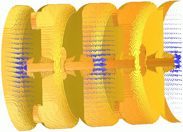
14 Pi-mode structures: the PIMS PIMS = Pi-Mode Structure, will be used in Linac4 at CERN to accelerate protons from to 6 MeV (β >.4) 7 cells magnetically coupled, 35 MHz Operating in π-mode, cell length βλ/ RF input Frequency Cells in a cavity have the same length. When more cavities are used for acceleration, the cells are longer from one cavity to the next, to follow the increase in beam velocity. 4
15 Sequence of PIMS cavities Cells have same length inside a cavity (7 cells) but increase from one cavity to the next. At high energy (> MeV) beta changes slowly and phase error ( phase slippage ) is small. 6 MeV, 55 cm Focusing quadrupoles between cavities MeV, 8 cm (v/c)^ PIMS range 3 Kinetic Energy [Me 5

 and electrons (ILC, etc.")

16 Pi-mode superconducting structures (elliptical) Standing wave structures for particles at β>.5-.7, widely used for protons (SNS, etc.) and electrons (ILC, etc.) f=35-7 MHz (protons), f=35 MHz 3 GHz (electrons) Chain of cells electrically coupled, large apertures (ZT not a concern). Operating in π-mode, cell length βλ/ Input coupler placed at one end. 6
17 Coupling between two cavities In the PIMS, cells are coupled via a slot in the walls. But what is the meaning of coupling, and how can we achieve a given coupling? Simplest case: resonators coupled via a slot Described by a system of equations: ω X ( ) + kx ω ω kx + X ( ) ω ω = c, = ω = + k or ω ω k k ω ω If ω =ω =ω, usual solutions (mode and mode π): with X X = and ω X X c, = ω = k with Mode + + (field in phase in the resonators) and mode + - (field with opposite phase) Taking the difference between the solutions (squared), approximated for k<< ω c, ω ω c, = k + k k or X X = c, ω ω The coupling k is equal to the difference between highest and lowest frequencies. k is the bandwidth of the coupled system. ω E-field mode E-field mode c, k
18 More on coupling Solving the previous equations allowing a different frequency for each cell, we can plot the frequencies of the coupled system as a function of the frequency of the first resonator, keeping the frequency of the second constant, for different values of the coupling k. Coupled freqeuencies [MHz] Frequency f [MHz] For an elliptical coupling slot: k F l 3 H U H U maximum separation when f=f F = slot form factor l = slot length (in the direction of H) H = magnetic field at slot position U = stored energy f f Coupling only when the resonators are close in frequency. - For f =f, maximum spacing between the frequencies (=kf ) The coupling k is: Proportional to the 3 rd power of slot length. Inv. proportional to the stored energies. fc fc fc fc fc fc case of 3 different coupling factors (.%, 5%, %)
19 Long chains of linac cells To reduce RF cost, linacs use high-power RF sources feeding a large number of coupled cells (DTL: 3-4 cells, other high-frequency structures can have > cells). But long linac structures (operating in or π mode) become extremely sensitive to mechanical errors: small machining errors in the cells can induce large differences in the accelerating field between cells. ω E mode π/ π k mode π 9
20 Stability of long chains of coupled resonators Mechanical errors differences in frequency between cells to respect the new boundary conditions the electric field will be a linear combination of all modes, with weight f f (general case of small perturbation to an eigenmode system, the new solution is a linear combination of all the individual modes) The nearest modes have the highest effect, and when there are many modes on the dispersion curve (number of modes = number of cells, but the total bandwidth is fixed = k!) the difference in E-field between cells can be extremely high. mode mode π/ mode π/3 mode π ω E π/ π k z
21 Stabilization of long chains: the π/ mode Solution: Long chains of linac cells can be operated in the π/ mode, which is intrinsically insensitive to differences in the cell frequencies. ω Perturbing mode mode π/ π/ π k Operating mode Perturbing mode Contribution from adjacent modes proportional to with the sign!!! f f The perturbation will add a component E/(f -f o ) for each of the nearest modes. Contributions from equally spaced modes in the dispersion curve will cancel each other.

22 Pi/ mode structures: the Side Coupled Linac To operate efficiently in the π/ mode, the cells that are not excited can be removed from the beam axis they are called coupling cells, as for the Side Coupled Structure. E-field Example: the Cell-Coupled Linac at the SNS linac, 85 MHz, - MeV, > cells/module


 Annular ring")
23 Examples of π/ structures π/-mode in a coupled-cell structure On axis Coupled Structure (OCS) Annular ring Coupled Structure (ACS) Side Coupled Structure (SCS) 3
 Series of DTL-like tanks with 3 cells (operating in -mode), coupled")

24 A mixed case: the Cell- Coupled Drift Tube Linac DTL-like tank ( drift tubes) Coupling cell DTL-like tank ( drift tubes) Series of DTL-like tanks with 3 cells (operating in -mode), coupled by coupling cells (operation in π/ mode) 35 MHz, will be used for the CERN Linac4 in the range 4- MeV. The coupling cells leave space for focusing quadrupoles between tanks. Waveguide input coupler 4


25 Pi/ mode: the DTL with post-couplers Postcoupler In a DTL, can be added post-couplers on a plane perpendicular to the stems. Each post is a resonator that can be tuned to the same frequency as the main -mode and coupled to this mode to double the chain of resonators allowing operation in stabilised π/-like mode! The equivalent circuit becomes extremely complicated and tuning is an issue, but π/ stabilization is very effective and allows having long DTL tanks! TM modes Stem modes PC modes MHz mode number 5
 H f <~ 3 MHz β ~ <.3 EA V Y IO N S H () 5-6 MHz.")
26 Alternative modes: H- mode structures R F Q f <~ β ~ < H MHz.3 Low and Medium - β Structures in H-Mode Operation H - 4 MHz β ~ <. LIGHT IONS Interdigital-H Structure Operates in TE mode Transverse E-field deflected by adding drift tubes Used for ions, β<.3 D T L H () H f <~ 3 MHz β ~ <.3 EA V Y IO N S H () 5-6 MHz.6 β < ~ CH Structure operates in TE, used for protons at β<.6 High ZT but more difficult beam dynamics (no space for quads in drift tubes) HSI IH DTL, 36 MHz B -- E Interdigital H-Mode (IH) B ++ E Crossbar H-Mode (CH) 6
27 Comparison of structures Shunt impedance Main figure of merit is the shunt impedance Ratio between energy gain (square) and power dissipation, is a measure of the energy efficiency of a structure. Depends on the beta, on the energy and on the mode of operation. However, the choice of the best accelerating structure for a certain energy range depends also on beam dynamics and on construction cost. Comparison of shuntimpedances for different lowbeta structures done in 5-8 by the HIPPI EU-funded Activity. In general terms, a DTL-like structure is preferred at lowenergy, and π-mode structures at high-energy. CH is excellent at very low energies (ions). 7
28 Traveling wave accelerating structures (electrons) What happens if we have an infinite chain of oscillators? X ( q) n ω ω =, q = N q π q,..., becomes (N h) + k cos N = ( const) π qn cos e N jω t q q =,..., N becomes (N h) ω ω = + k cosϕ X i = ( const) e jω t q ω / -k frequency wq ω / +k ω π/ π phase shift per oscillator φ=πq/n All modes in the dispersion curve are allowed, the original frequency degenerates into a continuous band. The field is the same in each cell, there are no more standing wave modes only traveling wave modes, if we excite the EM field at one end of the structure it will propagate towards the other end. But: our dispersion curve remains valid, and defines the velocity of propagation of the travelling wave, v φ = ωd/φ For acceleration, the wave must propagate at v φ = c for each frequency ω and cell length d we can find a phase Φ where the apparent velocity of the wave v φ is equal to c 8
29 Superconducting lowbeta structures 9
30 General architecture For Superconducting structures:. Shunt impedance and power dissipation are not a concern.. Power amplifiers are small (and relatively inexpensive) solid-state units. can be used the independent cavity architecture, which allows some flexibility in the range of beta and e/m of the particles to be accelerated. d In particular, SC structures are convenient for machines operating at high duty cycle. At low duty, static cryogenic losses are predominant (many small cavities!) However, even for SC linacs single-gap cavities are expensive to produce (and lead to larger cryogenic dissipation) double or triple-gap resonators are commonly used! 3
 is guaranteed only for one energy/velocity, while for easiness of construction a linac is composed by series of identical QWR s reduction of energy gain")
31 Quarter Wave Resonators Simple -gap cavities commonly used in SC version (lead, niobium, sputtered niobium) for low beta protons or ion linacs, where ~CW operation is required. Synchronicity (distance βλ/ between the gaps) is guaranteed only for one energy/velocity, while for easiness of construction a linac is composed by series of identical QWR s reduction of energy gain for off-energy cavities, Transit Time Factor (= ratio between actual energy gained and maximum energy gain) curves as below: phase slippage 3


32 The Spoke cavity Another option: Double or triple-spoke cavity, can be used at higher energy (- MeV for protons and triple-spoke). HIPPI Triple-spoke cavity prototype built at FZ Jülich, now under test at IPNO 3
![The superconducting zoo Spoke (low beta) [FZJ, Orsay]](/docs-images/78/77299559/images/33-0.jpg "CH (low/medium beta) [IAP-FU] QWR (low beta) [LNL,")
![etc.] HWR (low beta) [FZJ, LNL, Orsay] Reentrant](/docs-images/78/77299559/images/33-2.jpg "[LNL] Superconducting linacs for low and medium beta")


33 The superconducting zoo Spoke (low beta) [FZJ, Orsay] CH (low/medium beta) [IAP-FU] QWR (low beta) [LNL, etc.] HWR (low beta) [FZJ, LNL, Orsay] Reentrant [LNL] Superconducting linacs for low and medium beta ions are made of multigap ( to 4) individual cavities, spaced by focusing elements. Advantages: can be individually phased linac can accept different ions Allow more space for focusing ideal for low β CW proton linacs 33
34 Questions on Module 3? - Coupled resonator chains - Stabilization - Periodic structures - Superconducting low-beta structures 34
This lecture recalls the main concepts introduced at the basic CAS course following an alternative approach and going more deeply into some specific
 This lecture recalls the main concepts introduced at the basic CAS course following an alternative approach and going more deeply into some specific issues 1. Introduction: building blocks, synchronicity
Linac JUAS lecture summary
 Linac JUAS lecture summary Part1: Introduction to Linacs Linac is the acronym for Linear accelerator, a device where charged particles acquire energy moving on a linear path. There are more than 20 000
1. Why linear accelerators - basic concepts. 3. Overview of linac structures. 5. More on periodic structures 6. The RFQ 7.
 Introduction to RF Linear Accelerators Maurizio Vretenar CERN AB/RF 1. Why linear accelerators - basic concepts 2. Periodic Accelerating Structures 3. Overview of linac structures 4. Basics of linac beam
Linear Accelerators. 1 Introduction. M. Vretenar CERN, Geneva, Switzerland
 Published by CERN in the Proceedings of the CAS-CERN Accelerator School: Advanced Accelerator Physics, Trondheim, Norway, 19 29 August 2013, edited by W. Herr, CERN-2014-009 (CERN, Geneva, 2014) Linear
Elliptical Cavities: Proven SRF Option
 Elliptical Cavities: Proven SRF Option Terry L. Grimm Michigan State University July 2005 Outline Multi-cell elliptical cavities Demonstrated for β > 0.4 Future trends Multi-spoke cavities Limited experimental
CERN Accelerator School. RF Cavities. Erk Jensen CERN BE-RF
 CERN Accelerator School RF Cavities Erk Jensen CERN BE-RF CERN Accelerator School, Varna 010 - "Introduction to Accelerator Physics" What is a cavity? 3-Sept-010 CAS Varna/Bulgaria 010- RF Cavities Lorentz
RF Linear accelerators L5: Longitudinal and Transverse Dynamics in Linacs
 RF Linear accelerators L5: Longitudinal and Transverse Dynamics in Linacs Dr Graeme Burt Lancaster University ( some elements from Wangler, RF Linear accelerators, S. Henderson UPSAS and M. Vrentinar Linear
Compact Linac for Deuterons (Based on IH Structures with PMQ Focusing)
") Compact Linac for Deuterons (Based on IH Structures with PMQ Focusing) S. Kurennoy, J. O Hara, L. Rybarcyk LANL, Los Alamos, NM Thanks to D. Barlow, F. Neri, and T. Wangler We are developing a compact
Compact Linac for Deuterons (Based on IH Structures with PMQ Focusing) S. Kurennoy, J. O Hara, L. Rybarcyk LANL, Los Alamos, NM Thanks to D. Barlow, F. Neri, and T. Wangler We are developing a compact
Comparative Assessment of HIPPI Normal Conducting Structures
 Comparative Assessment of HIPPI Normal Conducting Structures C. Plostinar (Editor) Rutherford Appleton Laboratory, UK Abstract Over the last five years important developments needed for high intensity
Modules 5&6. Beam dynamics overview and Linac architecture
 Modules 5&6 Beam dynamics overview and Linac architecture 1 Introduction General problem: Need accurate beam optics design to minimize beam loss and emittance growth, to Reduce the requirements on the
RF LINACS. Alessandra Lombardi BE/ ABP CERN
 1 RF LINACS Alessandra Lombardi BE/ ABP CERN Contents PART 1 (yesterday) : Introduction : why?,what?, how?, when? Building bloc I (1/) : Radio Frequency cavity From an RF cavity to an accelerator PART
Short Introduction to CLIC and CTF3, Technologies for Future Linear Colliders
 Short Introduction to CLIC and CTF3, Technologies for Future Linear Colliders Explanation of the Basic Principles and Goals Visit to the CTF3 Installation Roger Ruber Collider History p p hadron collider
Cavity basics. 1 Introduction. 2 From plane waves to cavities. E. Jensen CERN, Geneva, Switzerland
 Cavity basics E. Jensen CERN, Geneva, Switerland Abstract The fields in rectangular and circular waveguides are derived from Maxwell s equations by superposition of plane waves. Subsequently the results
Longitudinal dynamics Yannis PAPAPHILIPPOU CERN
 Longitudinal dynamics Yannis PAPAPHILIPPOU CERN United States Particle Accelerator School, University of California - Santa-Cruz, Santa Rosa, CA 14 th 18 th January 2008 1 Outline Methods of acceleration
Bernhard Holzer, CERN-LHC
 Bernhard Holzer, CERN-LHC * Bernhard Holzer, CERN CAS Prague 2014 x Liouville: in reasonable storage rings area in phase space is constant. A = π*ε=const x ε beam emittance = woozilycity of the particle
Longitudinal Dynamics
 Longitudinal Dynamics F = e (E + v x B) CAS Bruges 16-25 June 2009 Beam Dynamics D. Brandt 1 Acceleration The accelerator has to provide kinetic energy to the charged particles, i.e. increase the momentum
Spoke and other TEM-class superconducting cavities. J.L. Muñoz, ESS-Bilbao Academy-Industry Matching Event CIEMAT, Madrid, 27.May.
 Spoke and other TEM-class superconducting cavities J.L. Muñoz, ESS-Bilbao Academy-Industry Matching Event CIEMAT, Madrid, 27.May.2013 Outline Introduction Basic design of TEM cavities Cavity design issues
Longitudinal Beam Dynamics
 Longitudinal Beam Dynamics Shahin Sanaye Hajari School of Particles and Accelerators, Institute For Research in Fundamental Science (IPM), Tehran, Iran IPM Linac workshop, Bahman 28-30, 1396 Contents 1.
Acceleration to higher energies
 Acceleration to higher energies While terminal voltages of 20 MV provide sufficient beam energy for nuclear structure research, most applications nowadays require beam energies > 1 GeV How do we attain
De Prisco, Renato; Comunian, Michele; Grespan, Franscesco; Piscent, Andrea; Karlsson, Anders
 ESS DTL RF MODELIZATION: FIELD TUNING AND STABILIZATION De Prisco, Renato; Comunian, Michele; Grespan, Franscesco; Piscent, Andrea; Karlsson, Anders 2013 Link to publication Citation for published version
Superconducting RF Accelerators: Why all the interest?
 Superconducting RF Accelerators: Why all the interest? William A. Barletta Director, United States Particle Accelerator School Dept. of Physics, MIT The HEP prespective ILC PROJECT X Why do we need RF
Lecture 1 Introduction to RF for Accelerators. Dr G Burt Lancaster University Engineering
 Lecture 1 Introduction to RF for Accelerators Dr G Burt Lancaster University Engineering Electrostatic Acceleration + - - - - - - - + + + + + + Van-de Graaff - 1930s A standard electrostatic accelerator
Varying accelerating fields
 Varying accelerating fields Two approaches for accelerating with time-varying fields Linear Accelerators Circular Accelerators Use many accelerating cavities through which the particle beam passes once.
ANALYSIS OF HIGH ORDER MODES IN 1.3 GHZ CW SRF ELECTRON LINAC FOR A LIGHT SOURCE
 ANALYSIS OF HIGH ORDER MODES IN 1.3 GHZ CW SRF ELECTRON LINAC FOR A LIGHT SOURCE A. Sukhanov, A. Vostrikov, V. Yakovlev, Fermilab, Batavia, IL 60510, USA Abstract Design of a Light Source (LS) based on
Developmental Studies of High Current Proton Linac for ADS Program
 1 Developmental Studies of High Current Proton Linac for ADS Program P. Singh, S.V.L.S. Rao, Rajni Pande, Shweta Roy, Rajesh Kumar, Piyush Jain, P.K. Nema, S. Krishnagopal, R.K. Choudhury, S. Kailas, V.C.
Design of a Double Spoke Cavity for C-ADS
 Design of a Double Spoke Cavity for C-ADS JIANG Tian-Cai ( 蒋天才 ) 1,2 Huang Yu-Lu ( 黄玉璐 ) 1,2 HE Yuan( 何源 ) 1 LU Xiang-Yang ( 鲁向阳 ) 1,3 Zhang Sheng-Hu ( 张生虎 ) 1 1 Institute of Modern Physics, Chinese Academy
Historical developments. of particle acceleration
 Historical developments of particle acceleration Y.Papaphilippou N. Catalan-Lasheras USPAS, Cornell University, Ithaca, NY 20 th June 1 st July 2005 1 Outline Principles of Linear Acceleration Electrostatic
Lectures on accelerator physics
 Lectures on accelerator physics Lecture 3 and 4: Examples Examples of accelerators 1 Rutherford s Scattering (1909) Particle Beam Target Detector 2 Results 3 Did Rutherford get the Nobel Prize for this?
Physics 610. Adv Particle Physics. April 7, 2014
 Physics 610 Adv Particle Physics April 7, 2014 Accelerators History Two Principles Electrostatic Cockcroft-Walton Van de Graaff and tandem Van de Graaff Transformers Cyclotron Betatron Linear Induction
Accelerators Ideal Case
 Accelerators Ideal Case Goal of an accelerator: increase energy of CHARGED par:cles Increase energy ΔE = r 2 F dr = q ( E + v B)d r The par:cle trajectory direc:on dr parallel to v ΔE = increase of energy
Review of proposals of ERL injector cryomodules. S. Belomestnykh
 Review of proposals of ERL injector cryomodules S. Belomestnykh ERL 2005 JLab, March 22, 2005 Introduction In this presentation we will review injector cryomodule designs either already existing or under
Nicolas PICHOFF. France CEA-Direction d Île de France Service de Physique et Applications des Accélérateurs (SP2A)
") Nicolas PICHOFF France CEA-Direction d Île de France Service de Physique et Applications des Accélérateurs (SP2A) Topics Some common structures The Radio Frequency Quadrupole (RFQ) The Drift-Tube Linacs
Nicolas PICHOFF France CEA-Direction d Île de France Service de Physique et Applications des Accélérateurs (SP2A) Topics Some common structures The Radio Frequency Quadrupole (RFQ) The Drift-Tube Linacs
Frequency and time domain analysis of trapped modes in the CERN Proton Synchrotron
 Frequency and time domain analysis of trapped modes in the CERN Proton Synchrotron Serena Persichelli CERN Impedance and collective effects BE-ABP-ICE Abstract The term trapped mode refers to a resonance
Fundamental Concepts of Particle Accelerators III : High-Energy Beam Dynamics (2) Koji TAKATA KEK. Accelerator Course, Sokendai. Second Term, JFY2012
 Koji TAKATA KEK. Accelerator Course, Sokendai. Second Term, JFY2012") .... Fundamental Concepts of Particle Accelerators III : High-Energy Beam Dynamics (2) Koji TAKATA KEK koji.takata@kek.jp http://research.kek.jp/people/takata/home.html Accelerator Course, Sokendai Second
.... Fundamental Concepts of Particle Accelerators III : High-Energy Beam Dynamics (2) Koji TAKATA KEK koji.takata@kek.jp http://research.kek.jp/people/takata/home.html Accelerator Course, Sokendai Second
A high intensity p-linac and the FAIR Project
 A high intensity p-linac and the FAIR Project Oliver Kester Institut für Angewandte Physik, Goethe-Universität Frankfurt and GSI Helmholtzzentrum für Schwerionenforschung Facility for Antiproton and Ion
KONUS BEAM DYNAMICS DESIGNS USING H-MODE CAVITIES
 Proceedings of Hadron Beam 28, Nashville, Tennessee, USA WGB11 KONUS BEAM DYNAMICS DESIGNS USING H-MODE CAVITIES R. Tiede, U. Ratzinger, H. Podlech, C. Zhang, IAP, Universität Frankfurt/Main, Germany,
Introduction to Longitudinal Beam Dynamics
 Introduction to Longitudinal Beam Dynamics B.J. Holzer CERN, Geneva, Switzerland Abstract This chapter gives an overview of the longitudinal dynamics of the particles in an accelerator and, closely related
!"#$%$!&'()$"('*+,-')'+-$#..+/+,0)&,$%.1&&/$ LONGITUDINAL BEAM DYNAMICS
$('*+,-')'+-$#..+/+,0)&,$%.1&&/$ LONGITUDINAL BEAM DYNAMICS") LONGITUDINAL BEAM DYNAMICS Elias Métral BE Department CERN The present transparencies are inherited from Frank Tecker (CERN-BE), who gave this course last year and who inherited them from Roberto Corsini
LONGITUDINAL BEAM DYNAMICS Elias Métral BE Department CERN The present transparencies are inherited from Frank Tecker (CERN-BE), who gave this course last year and who inherited them from Roberto Corsini
Accelerators. There are some accelerators around the world Nearly all are for industrial (20 000) or clinical use (10 000)
 or clinical use (10 000)") Accelerators There are some 30 000 accelerators around the world Nearly all are for industrial (20 000) or clinical use (10 000) Scientific research community (~ 100) Synchrotron light sources Ion beam
Accelerators There are some 30 000 accelerators around the world Nearly all are for industrial (20 000) or clinical use (10 000) Scientific research community (~ 100) Synchrotron light sources Ion beam
Accelerator Physics. Tip World Scientific NEW JERSEY LONDON SINGAPORE BEIJING SHANGHAI HONG KONG TAIPEI BANGALORE. Second Edition. S. Y.
 Accelerator Physics Second Edition S. Y. Lee Department of Physics, Indiana University Tip World Scientific NEW JERSEY LONDON SINGAPORE BEIJING SHANGHAI HONG KONG TAIPEI BANGALORE Contents Preface Preface
Parameter Study and Coupled S-Parameter Calculations of Superconducting RF Cavities
 Parameter Study and Coupled S-Parameter Calculations of Superconducting RF Cavities Tomasz Galek, Thomas Flisgen, Korinna Brackebusch, Kai Papke and Ursula van Rienen CST European User Conference 24.05.2012,
Lecture 14 Date:
 Lecture 14 Date: 18.09.2014 L Type Matching Network Examples Nodal Quality Factor T- and Pi- Matching Networks Microstrip Matching Networks Series- and Shunt-stub Matching L Type Matching Network (contd.)
Preliminary design studies of a 100 MeV H /H + LINAC as injector for SNS synchrotron/ads LINAC
 PRAMANA cfl Indian Academy of Sciences Vol. 59, No. 5 journal of November 2002 physics pp. 859 869 Preliminary design studies of a 100 MeV H /H + LINAC as injector for SNS synchrotron/ads LINAC S A PANDE,
Particle physics experiments
 Particle physics experiments Particle physics experiments: collide particles to produce new particles reveal their internal structure and laws of their interactions by observing regularities, measuring
Status of linear collider designs:
 Status of linear collider designs: Main linacs Design overview, principal open issues G. Dugan March 11, 2002 Linear colliders: main linacs The main linac is the heart of the linear collider TESLA, NLC/JLC,
ELECTROMAGNETIC SIMULATION CODES FOR DESIGNING CAVITIES -1
 INDIAN INSTITUTE OF TECHNOLOGY ROORKEE ELECTROMAGNETIC SIMULATION CODES FOR DESIGNING CAVITIES -1 Puneet Jain IIT ROORKEE SRFSAT Workshop, IUAC N. Delhi September 21, 2017 2 OUTLINE 1. Overview of Electromagnetic
SAST Lecture - III. Linear Accelerators. P N Prakash. IUAC, New Delhi
 Lecture - III Linear Accelerators P N Prakash IUAC, New Delhi School on Accelerator Science and Technology (SAST ) Inter-University Accelerator Centre, New Delhi May 16-27, Outline: Lecture - III Figures
Beam instabilities (I)
") Beam instabilities (I) Giovanni Rumolo in CERN Accelerator School, Advanced Level, Trondheim Wednesday 21.08.2013 Big thanks to H. Bartosik, G. Iadarola, K. Li, N. Mounet, B. Salvant, R. Tomás, C. Zannini
Beam instabilities (I) Giovanni Rumolo in CERN Accelerator School, Advanced Level, Trondheim Wednesday 21.08.2013 Big thanks to H. Bartosik, G. Iadarola, K. Li, N. Mounet, B. Salvant, R. Tomás, C. Zannini
Linear and circular accelerators
 Linear and circular accelerators Ion Accelerator Physics and Technology Oliver Boine-Frankenheim, Gesellschaft für Schwerionenforschung (GSI), Darmstadt Tel. 06159 712408, O.Boine-Frankenheim@gsi.de o
Introduction to accelerators for teachers (Korean program) Mariusz Sapiński CERN, Beams Department August 9 th, 2012
 Mariusz Sapiński CERN, Beams Department August 9 th, 2012") Introduction to accelerators for teachers (Korean program) Mariusz Sapiński (mariusz.sapinski@cern.ch) CERN, Beams Department August 9 th, 2012 Definition (Britannica) Particle accelerator: A device producing
Introduction to accelerators for teachers (Korean program) Mariusz Sapiński (mariusz.sapinski@cern.ch) CERN, Beams Department August 9 th, 2012 Definition (Britannica) Particle accelerator: A device producing
TULIP all-linac: a high gradient linac for proton therapy
 TULIP all-linac: a high gradient linac for proton therapy S. Benedetti, A. Grudiev, and A. Latina CERN,CH-1211 Geneva-23, Switzerland (Dated: March 9, 2017) Proposed for the first time almost 30 years
Beam Dynamics. D. Brandt, CERN. CAS Bruges June 2009 Beam Dynamics D. Brandt 1
 Beam Dynamics D. Brandt, CERN D. Brandt 1 Some generalities D. Brandt 2 Units: the electronvolt (ev) The electronvolt (ev)) is the energy gained by an electron travelling, in vacuum, between two points
Design of a 10 MeV normal conducting CW proton linac based on equidistant multi-gap CH cavities *
 Design of a 10 MeV normal conducting CW proton linac based on equidistant multi-gap CH cavities * LI Zhi-Hui( ) 1) The Key Labratory of Radiation Physics and Technology of Ministy of Eduction, Institute
Traveling Wave Undulators for FELs and Synchrotron Radiation Sources
 LCLS-TN-05-8 Traveling Wave Undulators for FELs and Synchrotron Radiation Sources 1. Introduction C. Pellegrini, Department of Physics and Astronomy, UCLA 1 February 4, 2005 We study the use of a traveling
A RF FEEDBACK FOR DAΦNE. A. Gallo
 K K DAΦNE TECHNICAL NOTE INFN - LNF, Accelerator Division Frascati, May 18, 1992 Note: RF-6 A RF FEEDBACK FOR DAΦNE A. Gallo INTRODUCTION In the RF-5 DAΦNE note we showed that is possible to avoid Sands
Introduction to Accelerators. Scientific Tools for High Energy Physics and Synchrotron Radiation Research
 Introduction to Accelerators. Scientific Tools for High Energy Physics and Synchrotron Radiation Research Pedro Castro Introduction to Particle Accelerators DESY, July 2010 What you will see Pedro Castro
Physics design of a CW high-power proton Linac for accelerator-driven system
 PRAMANA c Indian Academy of Sciences Vol. 78, No. 2 journal of February 2012 physics pp. 247 255 for accelerator-driven system RAJNI PANDE, SHWETA ROY, S V L S RAO, P SINGH and S KAILAS Physics Group,
The CIS project and the design of other low energy proton synchrotrons
 The CIS project and the design of other low energy proton synchrotrons 1. Introduction 2. The CIS project 3. Possible CMS 4. Conclusion S.Y. Lee IU Ref. X. Kang, Ph.D. thesis, Indiana University (1998).
Operational Experience in PIAVI-ALPI Complex. E. Fagotti INFN-LNL
 Operational Experience in PIAVI-ALPI Complex E. Fagotti INFN-LNL Operational Experience in PIAVI-ALPI Complex E. Fagotti INFN-LNL Machine History Operational Experience in PIAVI-ALPI Complex E. Fagotti
The Spectrum of Particle Accelerators
 The Spectrum of Particle Accelerators JAI Accelerator Physics Course Lecture 1 Dr. Suzie Sheehy University of Oxford and ASTeC/STFC/RAL My contact details: suzie.sheehy@physics.ox.ac.uk Twitter: @suziesheehy
CERN Accelerator School Wakefields. Prof. Dr. Ursula van Rienen, Franziska Reimann University of Rostock
 CERN Accelerator School Wakefields Prof. Dr. Ursula van Rienen, Franziska Reimann University of Rostock Contents The Term Wakefield and Some First Examples Basic Concept of Wakefields Basic Definitions
NEW DEVELOPMENT IN HIGH POWER RFQ ACCELERATORS*
 NEW DEVELOPMENT IN HIGH POWER RFQ ACCELERATORS* A. Schempp Institut für Angewandte Physik, J. W. Goethe-Universität, D-60054 Frankfurt am Main, Germany Abstract RFQs are the standard solution for new ion
Development and application of the RFQs for FAIR and GSI Projects
 Development and application of the RFQs for FAIR and GSI Projects Stepan Yaramyshev GSI, Darmstadt Facility for Antiproton and Ion Research at Darmstadt The FAIR Accelerator Complex GSI Today SIS 100 SIS18
Why do we accelerate particles?
 Why do we accelerate particles? (1) To take existing objects apart 1803 J. Dalton s indivisible atom atoms of one element can combine with atoms of other element to make compounds, e.g. water is made of
Chopping High-Intensity Ion Beams at FRANZ
 Chopping High-Intensity Ion Beams at FRANZ C. Wiesner, M. Droba, O. Meusel, D. Noll, O. Payir, U. Ratzinger, P. Schneider IAP, Goethe-Universität Frankfurt am Main Outline 1) Introduction: The FRANZ facility
Linac4: From Initial Design to Final Commissioning
 Linac4: From Initial Design to Final Commissioning Alessandra M Lombardi for the LINAC4 Team 1 Oliver.Abevrle,Davide.Aguglia,Luca.Arnaudon,Philippe.Baudrenghien, Giulia.Bellodi Caterina.Bertone,Yannic.Body,Jan.Borburgh,Enrico.Bravin,Olivier.Brunner,Jean-
H-TYPE LINAC STRUCTURES
 H-TYPE LINAC STRUCTURES U. Ratzinger * GSI Darmstadt, Darmstadt, Germany Abstract H-type cavities have been successfully developed over the last 5 years to serve for a large variety of applications in
Arbitrary Patterning Techniques for Anisotropic Surfaces, and Line Waves
 Arbitrary Patterning Techniques for Anisotropic Surfaces, and Line Waves Dan Sievenpiper, Jiyeon Lee, and Dia a Bisharat January 11, 2016 1 Outline Arbitrary Anisotropic Surface Patterning Surface wave
The SARAF 40 MeV Proton/Deuteron Accelerator
 The SARAF 40 MeV Proton/Deuteron Accelerator I. Mardor, D. Berkovits, I. Gertz, A. Grin, S. Halfon, G. Lempert, A. Nagler, A. Perry, J. Rodnizki, L. Weissman Soreq NRC, Yavne, Israel K. Dunkel, M. Pekeler,
SPES Conceptual Design Report
 Source TRIPS 5MeV BNCT Be converter U target RFQ ISCL Ion source 100 MeV Isotope separator Charge breeder SPES Conceptual Design Report TECHNICAL COMMITTEE A. Pisent (Technical Coordinator) M. Comunian
D B. An Introduction to the Physics and Technology of e+e- Linear Colliders. Lecture 2: Main Linac. Peter (PT) Tenenbaum (SLAC)
 Tenenbaum (SLAC)") An Introduction to the Physics and Technology of e+e- Linear Colliders Lecture : Main Linac Peter (PT) Tenenbaum (SLAC) Nick Walker DESY DESY Summer Student Lecture USPAS Santa Barbara, CA, 16-7 31 st
An Introduction to the Physics and Technology of e+e- Linear Colliders Lecture : Main Linac Peter (PT) Tenenbaum (SLAC) Nick Walker DESY DESY Summer Student Lecture USPAS Santa Barbara, CA, 16-7 31 st
Lecture 5 Notes, Electromagnetic Theory II Dr. Christopher S. Baird, faculty.uml.edu/cbaird University of Massachusetts Lowell
 Lecture 5 Notes, Electromagnetic Theory II Dr. Christopher S. Baird, faculty.uml.edu/cbaird University of Massachusetts Lowell 1. Waveguides Continued - In the previous lecture we made the assumption that
LHC Luminosity and Energy Upgrade
 LHC Luminosity and Energy Upgrade Walter Scandale CERN Accelerator Technology department EPAC 06 27 June 2006 We acknowledge the support of the European Community-Research Infrastructure Activity under
1.5-GeV FFAG Accelerator as Injector to the BNL-AGS
 1.5-GeV FFAG Accelerator as Injector to the BNL-AGS Alessandro G. Ruggiero M. Blaskiewicz,, T. Roser, D. Trbojevic,, N. Tsoupas,, W. Zhang Oral Contribution to EPAC 04. July 5-9, 5 2004 Present BNL - AGS
Accelerators. W. Udo Schröder, 2004
 1 Accelerators Overview Electrostatic Accelerators Cascade Van de Graaff V.d.G. Tandem generator Accelerator 2-3 stages steady (DC) beam, high quality focusing, energy, currents; but low energies Accelerators
Transverse dynamics Selected topics. Erik Adli, University of Oslo, August 2016, v2.21
 Transverse dynamics Selected topics Erik Adli, University of Oslo, August 2016, Erik.Adli@fys.uio.no, v2.21 Dispersion So far, we have studied particles with reference momentum p = p 0. A dipole field
Accelerator Basics. Abhishek Rai IUAC
 Accelerator Basics Abhishek Rai IUAC School on Accelerator Science and Technology May 7-18, 2018 Some basics Charge on an electron(e) = 1.6 10-19 Coulomb (1 unit of charge) 1 Atomic mass unit (amu) = 1.66
Dr. Vahid Nayyeri. Microwave Circuits Design
 Lect. 8: Microwave Resonators Various applications: including filters, oscillators, frequency meters, and tuned amplifiers, etc. microwave resonators of all types can be modelled in terms of equivalent
Impedance & Instabilities
 Impedance & Instabilities The concept of wakefields and impedance Wakefield effects and their relation to important beam parameters Beam-pipe geometry and materials and their impact on impedance An introduction
Beam Shaping and Permanent Magnet Quadrupole Focusing with Applications to the Plasma Wakefield Accelerator
 Beam Shaping and Permanent Magnet Quadrupole Focusing with Applications to the Plasma Wakefield Accelerator R. Joel England J. B. Rosenzweig, G. Travish, A. Doyuran, O. Williams, B. O Shea UCLA Department
NMR Instrumentation BCMB/CHEM Biomolecular NMR
 NMR Instrumentation BCMB/CHEM 8190 Biomolecular NMR Instrumental Considerations - Block Diagram of an NMR Spectrometer Magnet Sample B 0 Lock Probe Receiver Computer Transmit Superconducting Magnet systems
Institute of Modern Physics, China Academy of Science, Lanzhou , China
 Submitted to Chinese Physics C KONUS Beam Dynamics Design of Uranium IH-DTL for HIAF Dou Wei-Ping( 窦为平 ) a He Yuan( 何源 ) a Lu Yuan-Rong( 陆元荣 ) b, a Institute of Modern Physics, China Academy of Science,
Development of the UNILAC towards a Megawatt Beam Injector
 Development of the UNILAC towards a Megawatt Beam Injector W. Barth, GSI - Darmstadt 1. GSI Accelerator Facility Injector for FAIR 2. Heavy Ion Linear Accelerator UNILAC 3. SIS 18 Intensity Upgrade Program
Lecture 5: Photoinjector Technology. J. Rosenzweig UCLA Dept. of Physics & Astronomy USPAS, 7/1/04
 Lecture 5: Photoinjector Technology J. Rosenzweig UCLA Dept. of Physics & Astronomy USPAS, 7/1/04 Technologies Magnetostatic devices Computational modeling Map generation RF cavities 2 cell devices Multicell
International Scientific Spring 2010, March 1-6, 1. R. Garoby. slhc
 International Scientific Spring 2010, March 1-6, 1 2010 R. Garoby slhc 1. Plans for future LHC injectors 2. Implementation stages 3. Final words R.G. 2 3/10/2009 R.G. 3 3 3/10/2009 Motivation 1. Reliability
Measurement Techniques for Engineers. Motion and Vibration Measurement
 Measurement Techniques for Engineers Motion and Vibration Measurement Introduction Quantities that may need to be measured are velocity, acceleration and vibration amplitude Quantities useful in predicting
BEAM DYNAMICS OF SPL: ISSUES AND SOLUTIONS
 BEAM DYNAMICS OF SPL: ISSUES AND SOLUTIONS P. A. Posocco, M. Eshraqi #, A. M. Lombardi, CERN, Geneva, Switzerland # and ESS Lund, Sweden Abstract SPL is a superconducting H- LINAC under study at CERN.
Evaluation of In-Vacuum Wiggler Wakefield Impedances for SOLEIL and MAX IV
 26/11/2014 European Synchrotron Light Source Workshop XXII 1 Evaluation of In-Vacuum Wiggler Wakefield Impedances for SOLEIL and MAX IV F. Cullinan, R. Nagaoka (SOLEIL, St. Aubin, France) D. Olsson, G.
Introduction to Elementary Particle Physics I
 Physics 56400 Introduction to Elementary Particle Physics I Lecture 9 Fall 2018 Semester Prof. Matthew Jones Particle Accelerators In general, we only need classical electrodynamics to discuss particle
Particles and Universe: Particle accelerators
 Particles and Universe: Particle accelerators Maria Krawczyk, Aleksander Filip Żarnecki March 24, 2015 M.Krawczyk, A.F.Żarnecki Particles and Universe 4 March 24, 2015 1 / 37 Lecture 4 1 Introduction 2
Compressor Lattice Design for SPL Beam
 EUROPEAN ORGANIZATION FOR NUCLEAR RESEARCH CERN A&B DIVISION AB-Note-27-34 BI CERN-NUFACT-Note-153 Compressor Lattice Design for SPL Beam M. Aiba Abstract A compressor ring providing very short proton
RLC Circuit (3) We can then write the differential equation for charge on the capacitor. The solution of this differential equation is
 We can then write the differential equation for charge on the capacitor. The solution of this differential equation is") RLC Circuit (3) We can then write the differential equation for charge on the capacitor The solution of this differential equation is (damped harmonic oscillation!), where 25 RLC Circuit (4) If we charge
RLC Circuit (3) We can then write the differential equation for charge on the capacitor The solution of this differential equation is (damped harmonic oscillation!), where 25 RLC Circuit (4) If we charge
Expressions for f r (T ) and Q i (T ) from Mattis-Bardeen theory
 and Q i (T ) from Mattis-Bardeen theory") 8 Appendix A Expressions for f r (T ) and Q i (T ) from Mattis-Bardeen theory The Mattis-Bardeen theory of the anomalous skin effect in superconductors [0] may be used to derive the behavior of the resonance
8 Appendix A Expressions for f r (T ) and Q i (T ) from Mattis-Bardeen theory The Mattis-Bardeen theory of the anomalous skin effect in superconductors [0] may be used to derive the behavior of the resonance
High Pressure, High Gradient RF Cavities for Muon Beam Cooling
 High Pressure, High Gradient RF Cavities for Muon Beam Cooling R. P. Johnson, R. E. Hartline, M. Kuchnir, T. J. Roberts Muons, Inc. C. M. Ankenbrandt, A. Moretti, M. Popovic Fermilab D. M. Kaplan, K. Yonehara
ILC Particle Sources -Electron and PositronMasao KURIKI (Hiroshima University)
") ILC Particle Sources -Electron and PositronMasao KURIKI (Hiroshima University) Introduction Electron Polarization is important for ILC. NEA GaAs is practically the only solution. Positron polarization
ILC Particle Sources -Electron and PositronMasao KURIKI (Hiroshima University) Introduction Electron Polarization is important for ILC. NEA GaAs is practically the only solution. Positron polarization
Optimization of the End Cells in SRF Cavities
 Optimization of the End Cells in SRF Cavities Jonathan Luk Universtity of California, San Diego, La Jolla, CA 92093 (Dated: August 12, 2005) The shape of the end cells of the RF superconducting cavities
Measurement and Compensation of Betatron Resonances at the CERN PS Booster Synchrotron
 Measurement and Compensation of Betatron Resonances at the CERN PS Booster Synchrotron Urschütz Peter (AB/ABP) CLIC meeting, 29.10.2004 1 Overview General Information on the PS Booster Synchrotron Motivation
Acceleration of Polarized Protons and Deuterons at COSY
 Acceleration of Polarized Protons and Deuterons at COSY A. Lehrach, enable FIGURE Imperfection Resonances 0.0005 0.001 0.0015 resonance strength 0.001 0.0015 resonance strength FIGURE Tune-Jump System
Introduction Frankfurt Neutron Source at Stern-Gerlach-Zentrum FRANZ Development of new accelerator concepts for intense proton and ion beams. High in
 2009/12/16 Proton Linac for the Frankfurt Neutron Source Christoph Wiesner Introduction Frankfurt Neutron Source at Stern-Gerlach-Zentrum FRANZ Development of new accelerator concepts for intense proton
SPPC Study and R&D Planning. Jingyu Tang for the SPPC study group IAS Program for High Energy Physics January 18-21, 2016, HKUST
 SPPC Study and R&D Planning Jingyu Tang for the SPPC study group IAS Program for High Energy Physics January 18-21, 2016, HKUST Main topics Pre-conceptual design study Studies on key technical issues R&D