1. Why linear accelerators - basic concepts. 3. Overview of linac structures. 5. More on periodic structures 6. The RFQ 7.
|
|
|
- Whitney Gardner
- 5 years ago
- Views:
Transcription
1 Introduction to RF Linear Accelerators Maurizio Vretenar CERN AB/RF 1. Why linear accelerators - basic concepts 2. Periodic Accelerating Structures 3. Overview of linac structures 4. Basics of linac beam dynamics 5. More on periodic structures 6. The RFQ 7. Linac Technology 1
2 Why Linear Accelerators Linacs are mostly used for: 1. Low-Energy accelerators (injectors to synchrotrons s or stand-alone) for protons and ions, linear accelerators are synchronous with the RF fields in the region where velocity increases with energy. As soon as velocity is ~constant, synchrotrons are more efficient (multi-pass instead of single pass). 2. Production of high-intensity proton beams in comparison with synchrotrons, linacs can go to higher repetition rate, are less affected by resonances and have losses more distributed more suitable for high intensity beams (but in competition with cyclotrons ). 3. High energy lepton colliders for electrons at high energy, main advantage is the absence of synchrotron radiation. 2
3 Proton and Electron Velocity 1 electrons β 2 =(v/c) 2 as function of kinetic energy T for protons and electrons. (v/c)^2 Relativistic (Einstein) relation: Einstein () T = m c ( 1) = m c ( γ 1) v c protons Kinetic Energy [MeV] Classic (Newton) relation: 2 2 v 2 1 v T = m = mc ( ) c Protons (rest energy MeV): follow Newton mechanics up to some tens of MeV (Δv/v < 1% for W < 15 MeV) then slowly l become relativistic i ( Einstein ). i From the GeV range velocity is nearly constant (v~.95c at 2 GeV) linacs can cope with the increasing particle velocity, synchrotrons are more efficient for v nearly constant. Electrons (rest energy 511 kev, 1/1836 of protons): relativistic from the kev range (v~.1c at 2.5 kev) then increasing velocity up to the MeV range (v~.95c at 1.1 MeV) v~c after few meters of acceleration in a linac (typical gradient 1 MeV/m). 3
4 Synchronism condition The distance between accelerating gaps is proportional to particle velocity Beam Electric field (tti (at time t) z l=βλ/2 Example: a linac superconducting 4-cell accelerating structure Synchronism condition: t (travel between centers of cells) = T/2 l 1 β c βλ = l = = βc 2 f 2 f 2 1. In an ion linac cell length has to increase (up to a factor 2!) and the linac will be made of a sequence of different accelerating structures (changing cell length, frequency, operating mode, etc.) matched to the ion velocity. 2. For electron linacs, β =1, l =λ/2 An electron linac will be made of an injector + a series of identical accelerating structures, t with cells all the same length Note: in the example above, we have synchronism only if we neglect the increase in beta inside the structure! 4
5 Example: Superconducting Proton Linac The same Superconducting cavity design can be used for different proton beta s, just changing the cell length accordingly to beta. β=.52 β=.7 β=.8 β=1 CERN (old) SPL design, SC linac MeV, 68 m length, 23 cavities 5
6 2 Periodic Accelerating Structures 6
7 Wave propagation in a cylindrical pipe RF input λ p TM1 field configuration E-field B-field In a cylindrical waveguide different modes can propagate (=Electromagnetic field distributions, transmitting power and/or information). The field is the superposition of waves reflected by the metallic walls of the pipe velocity and wavelength of the modes will be different from free space (c, λ) To accelerate particles, we need a mode with longitudinal E-field component on axis: a TM mode (Transverse Magnetic, B z =). The simplest is TM1. We enter RF power at a frequency exciting the TM1 mode: E-field periodic on axis, wavelength λ p depends on frequency and on cylinder radius. Wave velocity (called phase velocity ) is v ph = λ p /T = λ p f = ω/k z with k z =2π/λ p The relation between frequency ω and propagation constant k is the DISPERSION RELATION (red curve on plot), a fundamental property of waveguides. 7
8 Wave velocity: the dispersion relation The relation ω(k) can be calculated from the standard theory of waveguides: ω 2 = k 2 c 2 + ω 2 c Plotting this curve (hyperbola), we see that: k=2π/λ p ω 1) There is a cut-off frequency, below which a wave will not propagate. It depends on dimensions vph>c (λ c =2.61a for the cylindrical waveguide). vph=c tg α = ω/kz = vph v ph =ω/k = (c 2 +ω c2 /k 2 ) 1/2 v g =dω/dk kz 2) At each excitation frequency is associated a phase velocity, the velocity at which a certain phase travels in the waveguide. v p = at k=, ω=ω c and then decreases towards v p =c for k,ω. 3) Energy (and information) travel at group velocity dω/dk, which is between and c. This velocity has to respect the relativity principle! 4) A particle traveling inside our cylinder has to travel at v = v ph to see a constant accelerating E- field should travel at v > c!!! 5) To use the waveguide to accelerate particles, we need a trick to slow down the wave. 8
9 Slowing down waves: the disc- loaded waveguide Discs inside the cylindrical waveguide, spaced by a distance l, will induce multiple reflections between the discs. s 9
10 Dispersion relation for the disc-loaded waveguide Wavelengths with λ p /2~ l will be most affected by the discs. On the contrary, for λ p = and λ p = the wave does not see the discs the dispersion curve remains that of the empty pipe. ω electric field pattern - mode A 6 mode B electric field pattern - mode B At λ p /2= l, the wave will be confined between the discs, and present 2 polarizations (mode A and B in the figure), 2 modes with same wavelength but different frequencies the dispersion curve splits into 2 branches, separated by a stop band open waveguide dispersion curve mode A In the disc-loaded waveguide, the lower branch of the dispersion curve is now distorted in such a way that we can find a range of frequencies with v ph = c we can use it to accelerate a particle beam! 1 4 k=2π/λ We have built a linac for v~c a TRAVELING WAVE (TW) ELECTRON LINAC 1
11 Traveling wave linac structures beam Disc-loaded waveguide designed for v ph =c at a given frequency, equipped with an input and an output coupler. RF power is introduced via the input coupler. Part of RF power is dissipated in the structure, part is taken by the beam (beam loading) and the rest is absorbed in a matched load at the end of the structure. Usually, structure length is such that ~3% of power goes to the load. The traveling wave structure is the standard linac for electrons from β~1. Can not be used for ions at v<c: 1. constant cell length does not allow synchronism 2. long structures, with no space for transverse focusing 11
12 Standing wave linac structures E d To obtain an accelerating structure for ions we close our disc-loaded structure at both ends with metallic walls multiple reflections of the waves. ω Boundary condition at both ends is that electric field must be perpendicular to the cover Only some modes on the disc-loaded dispersion curve are allowed only some frequencies on the dispersion curve are permitted. In general: 1. the modes allowed will be equally spaced in k The number of modes will be identical to the number of cells (N cells Nmodes) 3. k represents the phase difference between the field in adjacent cells. π/2 π 12 k
13 More on standing wave structures mode mode π/2 mode 2π/3 mode π E Standing wave modes are named from the phase difference between adjacent cells: in the example above, mode, π/2, 2π/3, π. In standing wave structures, cell length can be matched to the particle velocity! z These STANDING WAVE MODES are generated by the sum of 2 traveling waves in opposite directions, adding always in the same way in the different cells. For acceleration, the particles must be in phase with the E-field on axis. We have already seen the π mode: synchronism condition for cell length l = βλ/2. Standing wave structures can be used for any β ( ions and electrons) and can follow the increase in β of the ions. Synchronism conditions: -mode : l = βλ π/2 mode: 2 l = βλ/2 π mode: l = βλ/2 13
 1.")
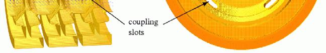
 we need to concentrate electric field on axis (Z ) and to shorten the gap (T )")

14 Practical standing wave structures From disc-loaded structure to a real cavity (Linac4 PIMS, Pi-Mode Structure) 1. To increase acceleration efficiency (=shunt impedance ZT 2!) we need to concentrate electric field on axis (Z ) and to shorten the gap (T ) introduction of noses on the openings. 2. The smaller opening would not allow the wave to propagate introduction of coupling slots between cells. 3. The RF wave has to be coupled into the cavity from one point, usually in the center. 14
15 Comparing traveling and standing wave structures Standing wave Traveling wave Chain of coupled cells in SW mode. Coupling (bw. cells) by slots (or open). Onaxis aperture reduced, higher E-field on axis and power efficiency. RF power from a coupling port, dissipated in the structure (ohmic loss on walls). Long pulses. Gradients 2-5 MeV/m Chain of coupled cells in TW mode Coupling bw. cells from on-axis aperture. RF power from input coupler at one end, dissipated in the structure and on a load. Short pulses, High frequency ( 3 GHz). Gradients 1-2 MeV/m Used for Ions and electrons at all Used for Electrons at v~c energies Comparable RF efficiencies 15
16 3 Examples of linac accelerating structures: a. protons, b. electrons, c. heavy ions 16
17 The Drift Tube Linac (Alvarez) Disc-loaded structures operating in -mode Add tubes for high shunt impedance 2 advantages of the -mode: 1. the fields are such that if we eliminate the walls between cells the fields are not affected, but we have less RF currents and higher shunt impedance. 2. The drift tubes can be long (~.75 βλ), the particles are inside the tubes when the electric field is decelerating, and we have space to introduce focusing elements (quadrupoles) inside the tubes. Maximize coupling between cells remove completely the walls 17
18 More on the DTL Quadrupole lens Drift tube Tuning plunger Standing wave linac structure for protons and ions, β=.1-.5, f=2-4 MHz Chain of coupled cells, completely open (no walls), maximum coupling. Operating in -mode, cell length βλ. Drift tubes are suspended by stems (no net current) Drift tubes contain focusing quadrupoles. Cavity shell Post coupler E-field B-field 18


.")
 quadrupoles inside")

19 Examples of DTL Top; CERN Linac2 Drift Tube Linac accelerating tank 1 (2 MHz). The tank is 7m long (diameter 1m) and provides an energy gain of 1 MeV. Left: DTL prototype for CERN Linac4 (352 MHz). Focusing is provided by (small) quadrupoles inside drift tubes. Length of drift tubes (cell length) increases with proton velocity. 19
20 Example: the Linac4 DTL beam 352 MHz frequency Tank diameter 5mm 3 resonators (tanks) Length 19 m 12 Drift Tubes Energy 3 MeV to 5 MeV Beta.8 to.31 cell length (βλ) 68mm to 264mm factor 3.9 increase in cell length 2


21 Multigap linac structures: the PIMS beam PIMS=PI Mode Structure Standing wave linac structure for protons, β > 4.4 Frequency 352 MHz Chain of coupled cells with coupling slots in walls. Operating in π-mode, d cell length βλ/2. 21
22 Sequence of PIMS cavities Cells have same length inside a cavity (7 cells) but increase from one cavity to the next. At high energy (>1 MeV) beta changes slowly and phase error ( phase slippage ) is small. 16 MeV, 155 cm Focusing quadrupoles between cavities 1 MeV, 128 cm (v/c )^2 PIMS range Kinetic Energy [Me 22


. 2.")
23 Proton linac architecture cell length, focusing period EXAMPLE: the Linac4 project at CERN. H-, 16 MeV energy, 352 MHz. A 3 MeV injector + 22 multi-cell standing wave accelerating structures of 3 types DTL: every cell is different, focusing quadrupoles in each drift tube CCDTL: sequences of 2 identical cells, quadrupoles every 3 cells PIMS: sequences of 7 identical cells, quadrupoles every 7 cells Two basic principles to remember: Injector 1. As beta increases, phase error between cells of identical length becomes small we can have short sequences of identical cells (lower construction costs). 2. As beta increases, the distance between focusing elements can increase (more details in 2 nd lecture!). 23
24 Proton linac architecture Shunt impedance A third basic principle: Every yproton linac structure has a characteristic curve of shunt impedance (=acceleration efficiency) as function of energy, which depends on the mode of operation. 3MeV 5MeV 1MeV 16MeV DTL Drift Tube Linac 18.7 m 3 tanks 3 klystrons CCDTL Cell-Coupled Drift Tube Linac 25 m 7 tanks 7 klystrons PIMS Pi-Mode Structure 22 m 12 tanks 8 klystrons The choice of the best accelerating structure for a certain energy range depends on shunt impedance, but also on beam dynamics and construction cost. 24
 Standing wave structures for")

 f=35-7 MHz (protons), f=35 MHz 3 GHz")
.")
25 Multi-gap Superconducting linac structures (elliptical) Standing wave structures for particles at β>.5-.7, widely used df for protons (SNS, etc.) and electrons (ILC, etc.) f=35-7 MHz (protons), f=35 MHz 3 GHz (electrons) Chain of cells electrically ll coupled, large apertures (ZT 2 not a concern). Operating in π-mode, cell length βλ/2 Input coupler placed at one end. 25
![Other superconducting structures for linacs Spoke (low beta) [FZJ, Orsay]](/docs-images/85/92452923/images/26-0.jpg "CH (low/medium beta) [IAP-FU] QWR (low beta) [LNL, etc.")
![] HWR (low beta) [FZJ, LNL, Orsay] Reentrant [LNL] Superconducting linacs](/docs-images/85/92452923/images/26-1.jpg "for low and medium beta ions are made of multigap (1 to 4) individual")

26 Other superconducting structures for linacs Spoke (low beta) [FZJ, Orsay] CH (low/medium beta) [IAP-FU] QWR (low beta) [LNL, etc.] HWR (low beta) [FZJ, LNL, Orsay] Reentrant [LNL] Superconducting linacs for low and medium beta ions are made of multigap (1 to 4) individual cavities, spaced by focusing elements. Advantages: can be individually phased linac can accept different ions Allow more space for focusing ideal for low β CW proton linacs 26


27 Quarter Wave Resonators Simple 2-gap cavities commonly used in their superconducting version (lead, niobium, sputtered niobium) for low beta protons or ion linacs, where ~CW operation is required. Synchronicity (distance βλ/2 between the 2 gaps) is guaranteed only for one energy/velocity, while for easiness of construction ti a linac is composed by series of identical QWR s reduction of energy gain for off-energy cavities, Transit Time Factor curves as below: phase slippage 27

 ++ ++ HSI IH DTL, 36 MHz - - - - B -- E Interdigital")
28 H-mode structures R F Q f <~ β ~ < H 11 1 MHz.3 Low and Medium - β Structures in H-Mode Operation H MHz β ~ <.12 LIGHT ION NS Interdigital-H Structure Operates in TE11 mode Transverse E-field deflected by adding drift tubes Used for ions, β<.3 D T L H 11 () H f <~ 3 MHz β ~ <.3 EA V Y IO N S H 21 () 25-6 MHz.6 β < ~ CH Structure operates in TE21, used for protons at β<.6 High ZT 2 but more difficult beam dynamics (no space for quads in drift tubes) HSI IH DTL, 36 MHz B -- E Interdigital H-Mode (IH) B ++ E Crossbar H-Mode (CH) 28
 The old CERN LIL (LEP")

29 Examples: an electron linac RF input RF output Focusing solenoids Accelerating structure (TW) The old CERN LIL (LEP Injector Linac) accelerating structures (3 GHz). The TW structure is surrounded by focusing solenoids, required for the positrons. 29


30 Examples: a TW accelerating structure A 3 GHz LIL accelerating structure used for CTF3. It is 4.5 meters long and provides an energy gain of 45 MeV. One can see 3 quadrupoles around the RF structure. 3
 at CERN: drive linac, 3")


31 Electron linac architecture EXAMPLE: the CLIC Test facility (CTF) at CERN: drive linac, 3 GHz, 184 MeV. An injector + a sequence of 2 identical multi-cell traveling wave accelerating structures. Main beam accelerator: 8 identical accelerating structures at 3 GHz, MeV 31


32 Examples: a heavy ion linac Particle source The REX heavy-ion post accelerators at CERN. It is made of 5 short standing wave accelerating structures at 1 MHz, spaced by focusing elements. Accelerating structures 32
33 Heavy Ion Linac Architecture EXAMPLE: the REX upgrade project at CERN-ISOLDE. Post-acceleration of radioactive ions with different A/q up to energy in the range 2-1 MeV. An injector (source, charge breeder, RFQ) + a sequence of short (few gaps) standing wave accelerating structures at frequency MHz, normal conducting at low energy (Interdigital, IH) and superconducting (Quarter Wave Resonators) at high energy mix of NC-SC, different structures, different frequencies. 1.2MeV/u for all A/q 1 to 14MeV/u depending on A/q 21.9 m 33
34 4 Beam Dynamics of Ion and Electron Linacs 34
35 Longitudinal dynamics Ions are accelerated around a (linac=negative) synchronous phase. Particles around the synchronous one perform oscillations in the longitudinal phase space. Frequency of small oscillations: ω 2 l = ω 2 ( ϕ ) qet sin 2 2π mc βγ 3 λ Tends to zero for relativistic particles γ>>1. Note phase damping of oscillations: Δϕ = const 3/ 4 ( β γ ) ΔW = const 3/ 4 ( β γ ) At relativistic velocities phase oscillations stop, the beam is compressed in phase around the initial phase. The crest of the wave can be used for acceleration. 35
36 Longitudinal dynamics - electrons Electrons at v=c remain at the injection phase. Electrons at v<c injected into a TW structure designed for v=c will move from injection phase ϕ to an asymptotic phase ϕ, which h depends d only on gradient and β at injection. The beam can be injected with an offset in phase, to reach the crest of the wave at β=1 Capture condition, relating E and β : 1 β = 1 1+ β 2 2π mc λ g qe Example: λ=1cm, W in =15 kev and E =8 MV/m. 2 2π mc 1 β 1 β sinϕ = sinϕ + λg qe 1 + β 1 + β I E injection β<1 acceleration β=1 φ In high h current linacs, a bunching and pre-acceleration sections up to 4-1 MeV prepares the injection in the TW structure (that occurs already on the crest) 36
37 Transverse dynamics - Space charge Large numbers of particles per bunch ( ~1 1 ). Coulomb repulsion between particles (space charge) plays an important t role. But space charge forces ~ 1/γ 2 disappear at relativistic velocity B Force on a particle inside a long bunch with density n(r) traveling at velocity v: E E r = e 2πε r r n( r) r dr B ϕ = μ ev 2π r r n( r) r dr 2 2 F = e( Er vbϕ ) = eer(1 ) = ee (1 β ) 2 r = v c ee γ r 2 37
38 Transverse dynamics - RF defocusing Bunch position at max E(t) RF defocusing experienced by particles crossing a gap on a longitudinally stable phase. In the rest frame of the particle, only electrostatic forces no stable points (maximum or minimum) radial defocusing. Lorentz transformation and calculation of radial momentum impulse per period (from electric and magnetic field contribution in the laboratory frame): Δ p r π e E T L r sinϕ = 2 2 c β γ λ Transverse defocusing ~ 1/γ 2 disappears at relativistic velocity (transverse magnetic force cancels the transverse RF electric force). Important consequence: in an electron linac, transverse and longitudinal dynamics are decoupled! 38
39 Transverse equilibrium in ion and electron linacs The equilibrium between external focusing force and internal defocusing forces defines the frequency of beam oscillations. Oscillations are characterized in terms of phase advance per focusing period σ t or phase advance per unit length k t. Ph. advance = Ext. quad focusing - RF defocusing - space charge Instabilities k 2 t = σ t Nβλ 2 = qgl 2 mc βγ 2 π q ET sin mc λ β γ ( ϕ ) 3q I λ( 1 f ) 8πε r 3 mc 3 β 2 γ 3... Approximate expression valid for: FD lattice, smooth focusing approximation, space charge of a uniform 3D ellipsoidal bunch. Electron Linac: Ph. advance = Ext. focusing + RF defocusing + space charge + Instabilities For γ>>1 (electron linac): RF defocusing and space charge disappear, phase advance. External focusing is required only to control the emittance and to stabilize the beam against instabilities (as wakefields and beam breakup). 39
40 Focusing gperiods Focusing provided by quadrupoles (but solenoids for low β!). Different distance between focusing elements (=1/2 length of a FODO focusing period)! For the main linac accelerating structure (after injector): Protons, (high beam current and high space charge) require short distances: - βλ in the DTL, from ~7mm (3 MeV, 352 MHz) to ~25mm (4 MeV), - can be increased to 4-1βλ at higher energy (>4 MeV). - longer focusing periods require special dynamics (example: the IH linac). Heavy ions (low current, no space charge): 2-1 βλ in the main linac (>~15mm). Electrons (no space charge, no RF defocusing): up to several meters, depending on the required beam conditions. Focusing is mainly required to control the emittance. 4
41 High-intensity protons the case of Linac4 Transverse (x) r.m.s. beam envelope along Linac4.3 x_rms bea am size [m].2.1 CCDTL : FODO PIMS : FODO DTL : FFDD and FODO distance from ion source [m] Example: beam dynamics design for Linac4@CERN. High intensity protons (6 ma bunch current, duty cycle could go up to 5%), 3-16 MeV Beam dynamics design minimising emittance growth and halo development in order to: 1. avoid uncontrolled beam loss (activation of machine parts) 2. preserve small emittance (high luminosity in the following accelerators) 41
42 Linac4 Dynamics - 2 Prescriptions: 1. Keep zero current phase advance always below 9º, to avoid resonances 2. Keep longitudinal l to transverse phase advance ratio , 8 to avoid emittance exchange 3. Keep a smooth variation of transverse and longitudinal phase advance per meter. 4. Keep sufficient safety margin between beam radius and aperture pha ase advance per meter kx ky kz E-7 4.E-7 3.5E-7 3.E-7 2.5E-7 1% Normalised RMS transverse emittance (PI m rad) x y transition transition position [m] 2.E Transverse r.m.s. emittance and phase advance along Linac4 (RFQ-DTL-CCDTL-PIMS) 42
43 5. Double periodic accelerating structures 43
44 Long chains of linac cells To reduce RF cost, linacs use high-power RF sources feeding a large number of coupled cells (DTL: 3-4 cells, other high-frequency structures can have >1 cells). Long linac structures operating in the or π modes are extremely sensitive to mechanical errors: small machining i errors in the cells can induce large differences in the accelerating field between cells. ω E mode π/2 π k mode π 44
45 Stability of long chains of coupled resonators Mechanical errors differences in E frequency between cells to respect the new boundary conditions mode the electric field will be a linear combination of all modes, with weight 1 mode π/2 2 2 f f (general case of small perturbation to an eigenmode system, the new solution is a linear combination of all the individual modes) The nearest modes have the highest effect, and when there are many modes on the dispersion curve (number of modes = number of cells!) the difference in E-field between cells can be extremely high. mode 2π/3 mode π ω π/ π k z 45
46 Stabilization of long chains: the π/2 mode Solution: Long chains of linac cells are operated in the π/2 mode, which is intrinsically insensitive to differences in the cell frequencies. ω Perturbing mode mode π/ π/2 π k Operating mode Perturbing mode 2 2 Contribution from adjacent modes proportional to f f with the sign!!! Contribution from equally spaced modes in the dispersion curve will cancel each other. 1 46


 Example: the Cell-Coupled Linac at")
47 The Side Coupled Linac To operate efficiently in the π/2 mode, the cells that are not excited can be removed from the beam axis they become coupling cells, as for the Side Coupled Structure. multi-cell Standing Wave structure in π/2 mode frequency 8-3 MHz for protons (β=.5-1) Example: the Cell-Coupled Linac at SNS, >1 cells/module 47


48 Examples of π/2 structures π/2-mode in a coupled-cell structure On axis Coupled Structure (OCS) Annular ring Coupled Structure (ACS) Side Coupled Structure (SCS) 48


49 The Cell-Coupled Drift Tube Linac Series of DTL-like DTL-like tank (2 drift tubes) tanks (-mode), coupled by coupling cells (π/2 mode) Waveguide input coupler Coupling cell DTL-like tank (2 drift tubes) 352 MHz, will be used for the CERN Linac4 in the range 4-1 MeV. Quadrupoles between tanks easier alignment, lower cost than standard DTL 49
50 6. The Radio Frequency Quadrupole 5
 At low proton (or ion)")


")
 new structure, the")

51 The Radio Frequency Quadrupole (RFQ) At low proton (or ion) energies, space charge defocusing is high and quadrupole focusing is not very effective, cell length becomes small conventional accelerating structures (Drift Tube Linac) are very inefficient use a (relatively) new structure, the Radio Frequency Quadrupole. RFQ = Electric quadrupole focusing channel + bunching + acceleration 51
 between which we excite an RF Quadrupole mode (TE21) Electric focusing channel,")

52 RFQ Qproperties p Four electrodes (vanes) between which we excite an RF Quadrupole mode (TE21) Electric focusing channel, alternating gradient with the period of the RF The vanes have a longitudinal modulation with period = βλ this creates a longitudinal component of the electric field. The modulation corresponds exactly to a series of RF gaps and can provide acceleration. + + Opposite vanes (18º) Adjacent vanes (9º) 52
53 RFQ Qproperties p The distance between peaks of the modulation can be slightly adjusted to change the phase of the beam inside the RFQ cells, and the amplitude of the modulation can be changed to change the accelerating gradient we can start at -9º phase (linac) with some bunching cells, progressively bunch the beam (adiabatic bunching channel), and only in the last cells switch on the acceleration. Longitudinal beam profile of a proton beam along the CERN RFQ2: from a continuous beam to a bunched accelerated beam in 3 cells. 53


 CERN High")
54 RFQ Modulation Designs modulation from the beginnig modulation -3-4 on modulati 1 max value =-35-5 phi (deg g).8.6 slow ramping from the beginning synchronous phase z (cm) CERN High intensity RFQ (RFQ2, 2 ma, 1.8m length) 54


55 How to create a quadrupole RF mode? The TE21 mode in the 4-vane structure and in the empty cavity Alternative resonator design: the 4-rod structure, where an array of λ/4 parallel plate lines load four rods, connected is such a way as to provide the quadrupole field. 55
56 7. Linac Technologies 56


 to produce the desired ion type.")
57 Particle production the sources Electron sources: give energy to the free electrons inside a metal to overcome the potential barrier at the boundary. Used for electron production: thermoionic effect laser pulses surface plasma Photo Injector Test Facility - Zeuthen RF Injection 1.5GHz Cs 2 Te Photo-Cathode or Mo Ion sources: create a plasma and optimise its conditions (heating, confinement and loss mechanisms) to produce the desired ion type. Remove ions from the plasma via an aperture and a strong electric field. CERN Duoplasmatron proton Source 262nm Laser Δ=.67ns 57
 Electron injector (CERN LIL) 3 common problems for")


58 Injectors for ion and electron linacs Ion injector (CERN Linac1) Electron injector (CERN LIL) 3 common problems for protons and electrons after the source, up to ~1 MeV energy: 1. large space charge defocusing 2. particle velocity rapidly increasing 3. need to form the bunches Solved by a special injector Ions: RFQ bunching, focusing and accelerating. Electrons: Standing wave bunching and pre-accelerating section. For all particles, the injector is where the emittance is created! 58
59 Accelerating structure: the choice of frequency approximate scaling laws for linear accelerators: RF defocusing g( (ion linacs) ~ frequency Cell length (=βλ/2) ~ (frequency) -1 Peak electric field ~ (frequency) 1/2 Shunt impedance (power efficiency) ~ (frequency) 1/2 Accelerating structure dimensions ~ (frequency) -1 Machining tolerances ~ (frequency) -1 Higher frequencies are economically convenient (shorter, less RF power, higher gradients possible) but limitation comes from mechanical precision in construction (tight tolerances are expensive!) and beam dynamics for ion linacs at low energy. Electron linacs tend to use higher frequencies (.5-12 GHz) than ion linacs. Standard frequency 3 GHz (1 cm wavelength). No limitations it ti from beam dynamics, iris i in TW structure requires less accurate machining than nose in SW structure. Proton linacs use lower frequencies (1-8 MHz), increasing with energy (ex.: 35 7 MHz): compromise between focusing, cost and size. Heavy ion linacs tend to use even lower frequencies (3-2 MHz), dominated by the 59 low beta in the first sections (CERN RFQ at 1MHz, 25 kev/u: βλ/2=3.5mm!)
 for electron linacs and modern proton")
 or solid state amplifiers for proton and heavy ion")
: brazed")

60 RF and construction technologies Type of RF power source depend on frequency: Klystrons (>35 MHz) for electron linacs and modern proton linacs. RF distribution via waveguides. RF tube (<4 MHz) or solid state amplifiers for proton and heavy ion linacs. RF distribution via coaxial lines. Construction technology depends on dimensions ( on frequency): brazed copper elements (>5 MHz) commonly used for electron linacs. copper or copper plated welded/bolted elements commonly used for ion linacs (<5 MHz). 3 GHz klystron (CERN LPI) 2 MHz triode amplifier (CERN Linac3) 6

 Beam in Wi W, Beam out")
 at high voltage (1-1 kv) Transforms DC power")

61 Example of a (Linac) RF System: transforms mains power into beam power Mains DC Power supply RF Amplifier (klystron or RF tube) RF line Cavity (accelerating structure) Beam in Wi W, Beam out W+ΔW, i Transforms mains power into DC power (pulsed or CW) at high voltage (1-1 kv) Transforms DC power Transforms RF power into RF power at high frequency into beam power 61 conversion efficiency~5% [efficiency shunt impedance]
.")

62 Modern trends in linacs What is new (& hot) in the field of linacs? 1. Frequencies are going up for both proton and electron linacs ( less expensive precision machining, i efficiency i scales s roughly as f). Modern proton linacs start at 35-4 MHz, end at 8-13 MHz. Modern electron linacs in the range 3-12 GHz. 2. Superconductivity is progressing fast, and is being presently used for both electron and ion linacs multi-cell ll standing wave structures in the frequency range from ~1 MHz to 13 MHz. Superconductivity is now bridging the gap between electron and ion linacs. The 9-cell TESLA/ILC SC cavities at 1.3 GHz for electron linear colliders, are now proposed for High Power Proton Accelerators (Fermilab 8 GeV linac)! 62
63 Bibliography 1. Reference Books: T. Wangler, Principles of RF Linear Accelerators (Wiley, New York, 1998). P. Lapostolle, A. Septier (editors), Linear Accelerators (Amsterdam, North Holland, 197). I.M. Kapchinskii, Theory of resonance linear accelerators (Harwood, Chur, 1985). 2. General Introductions to linear accelerators M. Puglisi, The Linear Accelerator, in E. Persico, E. Ferrari, S.E. Segré, Principles of Particle Accelerators (W.A. Benjamin, New York, 1968). P. Lapostolle, Proton Linear Accelerators: A theoretical and Historical Introduction, LA-1161-MS, P. Lapostolle, M. Weiss, Formulae and Procedures useful for the Design of Linear Accelerators, CERN- PS-2-1 (DR), 2. P. Lapostolle, R. Jameson, Linear Accelerators, in Encyclopaedia of Applied Physics (VCH Publishers, New York, 1991). 3. CAS Schools S. Turner (ed.), CAS School: Cyclotrons, Linacs and their applications, CERN 96-2 (1996). M. Weiss, Introduction ti to RF Linear Accelerators, in CAS School: Fifth General Accelerator Physics Course, CERN-94-1 (1994), p N. Pichoff, Introduction to RF Linear Accelerators, in CAS School: Basic Course on General Accelerator Physics, CERN-25-4 (25). M. Vretenar, Differences between electron and ion linacs, in CAS School: Small Accelerators, CERN
From the Wideröe gap to the linac cell
 Module 3 Coupled resonator chains Stability and stabilization Acceleration in periodic structures Special accelerating structures Superconducting linac structures From the Wideröe gap to the linac cell
This lecture recalls the main concepts introduced at the basic CAS course following an alternative approach and going more deeply into some specific
 This lecture recalls the main concepts introduced at the basic CAS course following an alternative approach and going more deeply into some specific issues 1. Introduction: building blocks, synchronicity
Linac JUAS lecture summary
 Linac JUAS lecture summary Part1: Introduction to Linacs Linac is the acronym for Linear accelerator, a device where charged particles acquire energy moving on a linear path. There are more than 20 000
Modules 5&6. Beam dynamics overview and Linac architecture
 Modules 5&6 Beam dynamics overview and Linac architecture 1 Introduction General problem: Need accurate beam optics design to minimize beam loss and emittance growth, to Reduce the requirements on the
RF LINACS. Alessandra Lombardi BE/ ABP CERN
 1 RF LINACS Alessandra Lombardi BE/ ABP CERN Contents PART 1 (yesterday) : Introduction : why?,what?, how?, when? Building bloc I (1/) : Radio Frequency cavity From an RF cavity to an accelerator PART
RF Linear accelerators L5: Longitudinal and Transverse Dynamics in Linacs
 RF Linear accelerators L5: Longitudinal and Transverse Dynamics in Linacs Dr Graeme Burt Lancaster University ( some elements from Wangler, RF Linear accelerators, S. Henderson UPSAS and M. Vrentinar Linear
Linear Accelerators. 1 Introduction. M. Vretenar CERN, Geneva, Switzerland
 Published by CERN in the Proceedings of the CAS-CERN Accelerator School: Advanced Accelerator Physics, Trondheim, Norway, 19 29 August 2013, edited by W. Herr, CERN-2014-009 (CERN, Geneva, 2014) Linear
Short Introduction to CLIC and CTF3, Technologies for Future Linear Colliders
 Short Introduction to CLIC and CTF3, Technologies for Future Linear Colliders Explanation of the Basic Principles and Goals Visit to the CTF3 Installation Roger Ruber Collider History p p hadron collider
Physics 610. Adv Particle Physics. April 7, 2014
 Physics 610 Adv Particle Physics April 7, 2014 Accelerators History Two Principles Electrostatic Cockcroft-Walton Van de Graaff and tandem Van de Graaff Transformers Cyclotron Betatron Linear Induction
Compact Linac for Deuterons (Based on IH Structures with PMQ Focusing)
") Compact Linac for Deuterons (Based on IH Structures with PMQ Focusing) S. Kurennoy, J. O Hara, L. Rybarcyk LANL, Los Alamos, NM Thanks to D. Barlow, F. Neri, and T. Wangler We are developing a compact
Compact Linac for Deuterons (Based on IH Structures with PMQ Focusing) S. Kurennoy, J. O Hara, L. Rybarcyk LANL, Los Alamos, NM Thanks to D. Barlow, F. Neri, and T. Wangler We are developing a compact
!"#$%$!&'()$"('*+,-')'+-$#..+/+,0)&,$%.1&&/$ LONGITUDINAL BEAM DYNAMICS
$('*+,-')'+-$#..+/+,0)&,$%.1&&/$ LONGITUDINAL BEAM DYNAMICS") LONGITUDINAL BEAM DYNAMICS Elias Métral BE Department CERN The present transparencies are inherited from Frank Tecker (CERN-BE), who gave this course last year and who inherited them from Roberto Corsini
LONGITUDINAL BEAM DYNAMICS Elias Métral BE Department CERN The present transparencies are inherited from Frank Tecker (CERN-BE), who gave this course last year and who inherited them from Roberto Corsini
Longitudinal Beam Dynamics
 Longitudinal Beam Dynamics Shahin Sanaye Hajari School of Particles and Accelerators, Institute For Research in Fundamental Science (IPM), Tehran, Iran IPM Linac workshop, Bahman 28-30, 1396 Contents 1.
Accelerators. There are some accelerators around the world Nearly all are for industrial (20 000) or clinical use (10 000)
 or clinical use (10 000)") Accelerators There are some 30 000 accelerators around the world Nearly all are for industrial (20 000) or clinical use (10 000) Scientific research community (~ 100) Synchrotron light sources Ion beam
Accelerators There are some 30 000 accelerators around the world Nearly all are for industrial (20 000) or clinical use (10 000) Scientific research community (~ 100) Synchrotron light sources Ion beam
Developmental Studies of High Current Proton Linac for ADS Program
 1 Developmental Studies of High Current Proton Linac for ADS Program P. Singh, S.V.L.S. Rao, Rajni Pande, Shweta Roy, Rajesh Kumar, Piyush Jain, P.K. Nema, S. Krishnagopal, R.K. Choudhury, S. Kailas, V.C.
Introduction to accelerators for teachers (Korean program) Mariusz Sapiński CERN, Beams Department August 9 th, 2012
 Mariusz Sapiński CERN, Beams Department August 9 th, 2012") Introduction to accelerators for teachers (Korean program) Mariusz Sapiński (mariusz.sapinski@cern.ch) CERN, Beams Department August 9 th, 2012 Definition (Britannica) Particle accelerator: A device producing
Introduction to accelerators for teachers (Korean program) Mariusz Sapiński (mariusz.sapinski@cern.ch) CERN, Beams Department August 9 th, 2012 Definition (Britannica) Particle accelerator: A device producing
Status of linear collider designs:
 Status of linear collider designs: Main linacs Design overview, principal open issues G. Dugan March 11, 2002 Linear colliders: main linacs The main linac is the heart of the linear collider TESLA, NLC/JLC,
Comparative Assessment of HIPPI Normal Conducting Structures
 Comparative Assessment of HIPPI Normal Conducting Structures C. Plostinar (Editor) Rutherford Appleton Laboratory, UK Abstract Over the last five years important developments needed for high intensity
Why do we accelerate particles?
 Why do we accelerate particles? (1) To take existing objects apart 1803 J. Dalton s indivisible atom atoms of one element can combine with atoms of other element to make compounds, e.g. water is made of
Longitudinal Dynamics
 Longitudinal Dynamics F = e (E + v x B) CAS Bruges 16-25 June 2009 Beam Dynamics D. Brandt 1 Acceleration The accelerator has to provide kinetic energy to the charged particles, i.e. increase the momentum
Preliminary design studies of a 100 MeV H /H + LINAC as injector for SNS synchrotron/ads LINAC
 PRAMANA cfl Indian Academy of Sciences Vol. 59, No. 5 journal of November 2002 physics pp. 859 869 Preliminary design studies of a 100 MeV H /H + LINAC as injector for SNS synchrotron/ads LINAC S A PANDE,
Longitudinal dynamics Yannis PAPAPHILIPPOU CERN
 Longitudinal dynamics Yannis PAPAPHILIPPOU CERN United States Particle Accelerator School, University of California - Santa-Cruz, Santa Rosa, CA 14 th 18 th January 2008 1 Outline Methods of acceleration
Lectures on accelerator physics
 Lectures on accelerator physics Lecture 3 and 4: Examples Examples of accelerators 1 Rutherford s Scattering (1909) Particle Beam Target Detector 2 Results 3 Did Rutherford get the Nobel Prize for this?
NEW DEVELOPMENT IN HIGH POWER RFQ ACCELERATORS*
 NEW DEVELOPMENT IN HIGH POWER RFQ ACCELERATORS* A. Schempp Institut für Angewandte Physik, J. W. Goethe-Universität, D-60054 Frankfurt am Main, Germany Abstract RFQs are the standard solution for new ion
Accelerator Physics. Tip World Scientific NEW JERSEY LONDON SINGAPORE BEIJING SHANGHAI HONG KONG TAIPEI BANGALORE. Second Edition. S. Y.
 Accelerator Physics Second Edition S. Y. Lee Department of Physics, Indiana University Tip World Scientific NEW JERSEY LONDON SINGAPORE BEIJING SHANGHAI HONG KONG TAIPEI BANGALORE Contents Preface Preface
Particle physics experiments
 Particle physics experiments Particle physics experiments: collide particles to produce new particles reveal their internal structure and laws of their interactions by observing regularities, measuring
Emittance preservation in TESLA
 Emittance preservation in TESLA R.Brinkmann Deutsches Elektronen-Synchrotron DESY,Hamburg, Germany V.Tsakanov Yerevan Physics Institute/CANDLE, Yerevan, Armenia The main approaches to the emittance preservation
ILC Particle Sources -Electron and PositronMasao KURIKI (Hiroshima University)
") ILC Particle Sources -Electron and PositronMasao KURIKI (Hiroshima University) Introduction Electron Polarization is important for ILC. NEA GaAs is practically the only solution. Positron polarization
ILC Particle Sources -Electron and PositronMasao KURIKI (Hiroshima University) Introduction Electron Polarization is important for ILC. NEA GaAs is practically the only solution. Positron polarization
CERN Accelerator School. RF Cavities. Erk Jensen CERN BE-RF
 CERN Accelerator School RF Cavities Erk Jensen CERN BE-RF CERN Accelerator School, Varna 010 - "Introduction to Accelerator Physics" What is a cavity? 3-Sept-010 CAS Varna/Bulgaria 010- RF Cavities Lorentz
Development and application of the RFQs for FAIR and GSI Projects
 Development and application of the RFQs for FAIR and GSI Projects Stepan Yaramyshev GSI, Darmstadt Facility for Antiproton and Ion Research at Darmstadt The FAIR Accelerator Complex GSI Today SIS 100 SIS18
Superconducting RF Accelerators: Why all the interest?
 Superconducting RF Accelerators: Why all the interest? William A. Barletta Director, United States Particle Accelerator School Dept. of Physics, MIT The HEP prespective ILC PROJECT X Why do we need RF
Elliptical Cavities: Proven SRF Option
 Elliptical Cavities: Proven SRF Option Terry L. Grimm Michigan State University July 2005 Outline Multi-cell elliptical cavities Demonstrated for β > 0.4 Future trends Multi-spoke cavities Limited experimental
TEST MEASUREMENTS WITH THE REX-ISOLDE LINAC STRUCTURES*
 TEST MEASUREMENTS WITH THE REX-ISOLDE LINAC STRUCTURES* O. Kester, D. Habs, T. Sieber, S. Emhofer, K. Rudolph, LMU München, Garching Germany R. von Hahn, H. Podlech, R. Repnow, D. Schwalm, MPI- K, Heidelberg,
Acceleration to higher energies
 Acceleration to higher energies While terminal voltages of 20 MV provide sufficient beam energy for nuclear structure research, most applications nowadays require beam energies > 1 GeV How do we attain
Design of an RF Photo-Gun (PHIN)
") Design of an RF Photo-Gun (PHIN) R. Roux 1, G. Bienvenu 1, C. Prevost 1, B. Mercier 1 1) CNRS-IN2P3-LAL, Orsay, France Abstract In this note we show the results of the RF simulations performed with a 2-D
Design of an RF Photo-Gun (PHIN) R. Roux 1, G. Bienvenu 1, C. Prevost 1, B. Mercier 1 1) CNRS-IN2P3-LAL, Orsay, France Abstract In this note we show the results of the RF simulations performed with a 2-D
Transverse dynamics Selected topics. Erik Adli, University of Oslo, August 2016, v2.21
 Transverse dynamics Selected topics Erik Adli, University of Oslo, August 2016, Erik.Adli@fys.uio.no, v2.21 Dispersion So far, we have studied particles with reference momentum p = p 0. A dipole field
$)ODW%HDP(OHFWURQ6RXUFHIRU/LQHDU&ROOLGHUV
ODW%HDP(OHFWURQ6RXUFHIRU/LQHDU&ROOLGHUV") $)ODW%HDP(OHFWURQ6RXUFHIRU/LQHDU&ROOLGHUV R. Brinkmann, Ya. Derbenev and K. Flöttmann, DESY April 1999 $EVWUDFW We discuss the possibility of generating a low-emittance flat (ε y
$)ODW%HDP(OHFWURQ6RXUFHIRU/LQHDU&ROOLGHUV R. Brinkmann, Ya. Derbenev and K. Flöttmann, DESY April 1999 $EVWUDFW We discuss the possibility of generating a low-emittance flat (ε y
Introduction to Collider Physics
 Introduction to Collider Physics William Barletta United States Particle Accelerator School Dept. of Physics, MIT The Very Big Picture Accelerators Figure of Merit 1: Accelerator energy ==> energy frontier
D. Brandt, CERN. CAS Frascati 2008 Accelerators for Newcomers D. Brandt 1
 Accelerators for Newcomers D. Brandt, CERN D. Brandt 1 Why this Introduction? During this school, you will learn about beam dynamics in a rigorous way but some of you are completely new to the field of
SLS at the Paul Scherrer Institute (PSI), Villigen, Switzerland
, Villigen, Switzerland") SLS at the Paul Scherrer Institute (PSI), Villigen, Switzerland Michael Böge 1 SLS Team at PSI Michael Böge 2 Layout of the SLS Linac, Transferlines Booster Storage Ring (SR) Beamlines and Insertion Devices
SLS at the Paul Scherrer Institute (PSI), Villigen, Switzerland Michael Böge 1 SLS Team at PSI Michael Böge 2 Layout of the SLS Linac, Transferlines Booster Storage Ring (SR) Beamlines and Insertion Devices
Introduction to Accelerators. Scientific Tools for High Energy Physics and Synchrotron Radiation Research
 Introduction to Accelerators. Scientific Tools for High Energy Physics and Synchrotron Radiation Research Pedro Castro Introduction to Particle Accelerators DESY, July 2010 What you will see Pedro Castro
BEAM DYNAMICS IN A HIGH FREQUENCY RFQ
 S. Myers : head of office for medical applications at CERN The 750MHz team (layout and beam dynamics, radio-frequeuncy and mechanics) : A. Dallocchio, V. A. Dimov, M. Garlasché, A. Grudiev, A. M. Lombardi,
Nicolas PICHOFF. France CEA-Direction d Île de France Service de Physique et Applications des Accélérateurs (SP2A)
") Nicolas PICHOFF France CEA-Direction d Île de France Service de Physique et Applications des Accélérateurs (SP2A) Topics Some common structures The Radio Frequency Quadrupole (RFQ) The Drift-Tube Linacs
Nicolas PICHOFF France CEA-Direction d Île de France Service de Physique et Applications des Accélérateurs (SP2A) Topics Some common structures The Radio Frequency Quadrupole (RFQ) The Drift-Tube Linacs
A high intensity p-linac and the FAIR Project
 A high intensity p-linac and the FAIR Project Oliver Kester Institut für Angewandte Physik, Goethe-Universität Frankfurt and GSI Helmholtzzentrum für Schwerionenforschung Facility for Antiproton and Ion
An Introduction to Particle Accelerators. v short
 An Introduction to Particle Accelerators v1.42 - short LHC FIRST BEAM 10-sep-2008 Introduction Part 1 Particle accelerators for HEP LHC: the world biggest accelerator, both in energy and size (as big as
Historical developments. of particle acceleration
 Historical developments of particle acceleration Y.Papaphilippou N. Catalan-Lasheras USPAS, Cornell University, Ithaca, NY 20 th June 1 st July 2005 1 Outline Principles of Linear Acceleration Electrostatic
Beam Dynamics for CSNS Linac. Jun Peng September. 18, 2012
 Beam Dynamics for CSNS Linac Jun Peng September. 18, 2012 Outline Beam loss study MEBT optimization DTL optimization Geometry Accelerating field and synchronous phase Focusing scheme End to end simulation
Beam Dynamics. D. Brandt, CERN. CAS Bruges June 2009 Beam Dynamics D. Brandt 1
 Beam Dynamics D. Brandt, CERN D. Brandt 1 Some generalities D. Brandt 2 Units: the electronvolt (ev) The electronvolt (ev)) is the energy gained by an electron travelling, in vacuum, between two points
Varying accelerating fields
 Varying accelerating fields Two approaches for accelerating with time-varying fields Linear Accelerators Circular Accelerators Use many accelerating cavities through which the particle beam passes once.
TULIP all-linac: a high gradient linac for proton therapy
 TULIP all-linac: a high gradient linac for proton therapy S. Benedetti, A. Grudiev, and A. Latina CERN,CH-1211 Geneva-23, Switzerland (Dated: March 9, 2017) Proposed for the first time almost 30 years
The CIS project and the design of other low energy proton synchrotrons
 The CIS project and the design of other low energy proton synchrotrons 1. Introduction 2. The CIS project 3. Possible CMS 4. Conclusion S.Y. Lee IU Ref. X. Kang, Ph.D. thesis, Indiana University (1998).
Introduction to Elementary Particle Physics I
 Physics 56400 Introduction to Elementary Particle Physics I Lecture 9 Fall 2018 Semester Prof. Matthew Jones Particle Accelerators In general, we only need classical electrodynamics to discuss particle
Studies of trapped modes in the new extraction septum of the CERN Proton Synchrotron
 Studies of trapped modes in the new extraction septum of the CERN Proton Synchrotron Serena Persichelli CERN Impedance and collective effects (BE-ABP-ICE) LIU LHC Injectors Upgrade project Università di
Fundamental Concepts of Particle Accelerators V: Future of the High Energy Accelerators VI: References. Koji TAKATA KEK. Accelerator Course, Sokendai
 .... Fundamental Concepts of Particle Accelerators V: Future of the High Energy Accelerators VI: References Koji TAKATA KEK koji.takata@kek.jp http://research.kek.jp/people/takata/home.html Accelerator
Tools of Particle Physics I Accelerators
 Tools of Particle Physics I Accelerators W.S. Graves July, 2011 MIT W.S. Graves July, 2011 1.Introduction to Accelerator Physics 2.Three Big Machines Large Hadron Collider (LHC) International Linear Collider
The CERN Accelerator School holds courses in all of the member states of CERN. 2013, Erice, Italy
 The CERN Accelerator School holds courses in all of the member states of CERN 2013, Erice, Italy Superconductivity for Accelerators Numerous changes in last weeks Background RF Magnets Technology Case
CERN EUROPEAN ORGANIZATION FOR NUCLEAR RESEARCH CTF3 DRIVE BEAM INJECTOR OPTIMISATION
 CERN EUROPEAN ORGANIZATION FOR NUCLEAR RESEARCH CLIC Note 1060 CTF3 DRIVE BEAM INJECTOR OPTIMISATION - 1 Sh. Sanaye Hajari 1, 2, * H. Shaker 1, 2 and S. Doebert 2 Institute for Research in Fundamental
Introduction to Longitudinal Beam Dynamics
 Introduction to Longitudinal Beam Dynamics B.J. Holzer CERN, Geneva, Switzerland Abstract This chapter gives an overview of the longitudinal dynamics of the particles in an accelerator and, closely related
Fundamental Concepts of Particle Accelerators V : Future of the High Energy Accelerators. Koji TAKATA KEK. Accelerator Course, Sokendai
 .... Fundamental Concepts of Particle Accelerators V : Future of the High Energy Accelerators Koji TAKATA KEK koji.takata@kek.jp http://research.kek.jp/people/takata/home.html Accelerator Course, Sokendai
CEPC Linac Injector. HEP Jan, Cai Meng, Guoxi Pei, Jingru Zhang, Xiaoping Li, Dou Wang, Shilun Pei, Jie Gao, Yunlong Chi
 HKUST Jockey Club Institute for Advanced Study CEPC Linac Injector HEP218 22 Jan, 218 Cai Meng, Guoxi Pei, Jingru Zhang, Xiaoping Li, Dou Wang, Shilun Pei, Jie Gao, Yunlong Chi Institute of High Energy
Contents. LC : Linear Collider. µ-µ Collider. Laser-Plasma Wave Accelerator. Livingston Chart 6 References
 .... Fundamental Concepts of Particle Accelerators V : Future of the High Energy Accelerators VI : References Koji TAKATA KEK koji.takata@kek.jp http://research.kek.jp/people/takata/home.html Accelerator
SRF GUN CHARACTERIZATION - PHASE SPACE AND DARK CURRENT MEASUREMENTS AT ELBE*
 SRF GUN CHARACTERIZATION - PHASE SPACE AND DARK CURRENT MEASUREMENTS AT ELBE* E. Panofski #, A. Jankowiak, T. Kamps, Helmholtz-Zentrum Berlin, Berlin, Germany P.N. Lu, J. Teichert, Helmholtz-Zentrum Dresden-Rossendorf,
Physics design of a CW high-power proton Linac for accelerator-driven system
 PRAMANA c Indian Academy of Sciences Vol. 78, No. 2 journal of February 2012 physics pp. 247 255 for accelerator-driven system RAJNI PANDE, SHWETA ROY, S V L S RAO, P SINGH and S KAILAS Physics Group,
6 Bunch Compressor and Transfer to Main Linac
 II-159 6 Bunch Compressor and Transfer to Main Linac 6.1 Introduction The equilibrium bunch length in the damping ring (DR) is 6 mm, too long by an order of magnitude for optimum collider performance (σ
Traveling Wave Undulators for FELs and Synchrotron Radiation Sources
 LCLS-TN-05-8 Traveling Wave Undulators for FELs and Synchrotron Radiation Sources 1. Introduction C. Pellegrini, Department of Physics and Astronomy, UCLA 1 February 4, 2005 We study the use of a traveling
Accelerator Physics Final Exam pts.
 Accelerator Physics Final Exam - 170 pts. S. M. Lund and Y. Hao Graders: C. Richard and C. Y. Wong June 14, 2018 Problem 1 P052 Emittance Evolution 40 pts. a) 5 pts: Consider a coasting beam composed of
Introduction to Accelerators
 Introduction to Accelerators D. Brandt, CERN CAS Platja d Aro 2006 Introduction to Accelerators D. Brandt 1 Why an Introduction? The time where each accelerator sector was working alone in its corner is
Graduate Accelerator Physics. G. A. Krafft Jefferson Lab Old Dominion University Lecture 1
 Graduate Accelerator Physics G. A. Krafft Jefferson Lab Old Dominion University Lecture 1 Course Outline Course Content Introduction to Accelerators and Short Historical Overview Basic Units and Definitions
Accelerator Physics and Technologies for Linear Colliders University of Chicago, Physics 575
 Accelerator Physics and Technologies for Linear Colliders University of Chicago, Physics 575 Lecture 1: S. D. Holmes, An Introduction to Accelerators for High Energy Physics I. Introduction to the Course
Institute of Modern Physics, China Academy of Science, Lanzhou , China
 Submitted to Chinese Physics C KONUS Beam Dynamics Design of Uranium IH-DTL for HIAF Dou Wei-Ping( 窦为平 ) a He Yuan( 何源 ) a Lu Yuan-Rong( 陆元荣 ) b, a Institute of Modern Physics, China Academy of Science,
Particles and Universe: Particle accelerators
 Particles and Universe: Particle accelerators Maria Krawczyk, Aleksander Filip Żarnecki March 24, 2015 M.Krawczyk, A.F.Żarnecki Particles and Universe 4 March 24, 2015 1 / 37 Lecture 4 1 Introduction 2
A Project to convert TLS Booster to hadron accelerator 1. Basic design. 2. The injection systems:
 A Project to convert TLS Booster to hadron accelerator 1. Basic design TLS is made of a 50 MeV electron linac, a booster from 50 MeV to 1.5 GeV, and a storage ring. The TLS storage ring is currently operating
TUNE SPREAD STUDIES AT INJECTION ENERGIES FOR THE CERN PROTON SYNCHROTRON BOOSTER
 TUNE SPREAD STUDIES AT INJECTION ENERGIES FOR THE CERN PROTON SYNCHROTRON BOOSTER B. Mikulec, A. Findlay, V. Raginel, G. Rumolo, G. Sterbini, CERN, Geneva, Switzerland Abstract In the near future, a new
Bernhard Holzer, CERN-LHC
 Bernhard Holzer, CERN-LHC * Bernhard Holzer, CERN CAS Prague 2014 x Liouville: in reasonable storage rings area in phase space is constant. A = π*ε=const x ε beam emittance = woozilycity of the particle
Review of proposals of ERL injector cryomodules. S. Belomestnykh
 Review of proposals of ERL injector cryomodules S. Belomestnykh ERL 2005 JLab, March 22, 2005 Introduction In this presentation we will review injector cryomodule designs either already existing or under
International Scientific Spring 2010, March 1-6, 1. R. Garoby. slhc
 International Scientific Spring 2010, March 1-6, 1 2010 R. Garoby slhc 1. Plans for future LHC injectors 2. Implementation stages 3. Final words R.G. 2 3/10/2009 R.G. 3 3 3/10/2009 Motivation 1. Reliability
Frequency and time domain analysis of trapped modes in the CERN Proton Synchrotron
 Frequency and time domain analysis of trapped modes in the CERN Proton Synchrotron Serena Persichelli CERN Impedance and collective effects BE-ABP-ICE Abstract The term trapped mode refers to a resonance
CERN EUROPEAN ORGANIZATION FOR NUCLEAR RESEARCH THE CLIC POSITRON CAPTURE AND ACCELERATION IN THE INJECTOR LINAC
 CERN EUROPEAN ORGANIZATION FOR NUCLEAR RESEARCH CLIC Note - 819 THE CLIC POSITRON CAPTURE AND ACCELERATION IN THE INJECTOR LINAC A. Vivoli 1, I. Chaikovska 2, R. Chehab 3, O. Dadoun 2, P. Lepercq 2, F.
Linac4: From Initial Design to Final Commissioning
 Linac4: From Initial Design to Final Commissioning Alessandra M Lombardi for the LINAC4 Team 1 Oliver.Abevrle,Davide.Aguglia,Luca.Arnaudon,Philippe.Baudrenghien, Giulia.Bellodi Caterina.Bertone,Yannic.Body,Jan.Borburgh,Enrico.Bravin,Olivier.Brunner,Jean-
Chopping High-Intensity Ion Beams at FRANZ
 Chopping High-Intensity Ion Beams at FRANZ C. Wiesner, M. Droba, O. Meusel, D. Noll, O. Payir, U. Ratzinger, P. Schneider IAP, Goethe-Universität Frankfurt am Main Outline 1) Introduction: The FRANZ facility
Introduction. Thermoionic gun vs RF photo gun Magnetic compression vs Velocity bunching. Probe beam design options
 Introduction Following the 19/05/04 meeting at CERN about the "CTF3 accelerated programme", a possible french contribution has been envisaged to the 200 MeV Probe Beam Linac Two machine options were suggested,
Spoke and other TEM-class superconducting cavities. J.L. Muñoz, ESS-Bilbao Academy-Industry Matching Event CIEMAT, Madrid, 27.May.
 Spoke and other TEM-class superconducting cavities J.L. Muñoz, ESS-Bilbao Academy-Industry Matching Event CIEMAT, Madrid, 27.May.2013 Outline Introduction Basic design of TEM cavities Cavity design issues
ASTRA simulations of the slice longitudinal momentum spread along the beamline for PITZ
 ASTRA simulations of the slice longitudinal momentum spread along the beamline for PITZ Orlova Ksenia Lomonosov Moscow State University GSP-, Leninskie Gory, Moscow, 11999, Russian Federation Email: ks13orl@list.ru
HIRFL STATUS AND HIRFL-CSR PROJECT IN LANZHOU
 HIRFL STATUS AND HIRFL-CSR PROJECT IN LANZHOU J. W. Xia, Y. F. Wang, Y. N. Rao, Y. J. Yuan, M. T. Song, W. Z. Zhang, P. Yuan, W. Gu, X. T. Yang, X. D. Yang, S. L. Liu, H.W.Zhao, J.Y.Tang, W. L. Zhan, B.
ANALYSIS OF HIGH ORDER MODES IN 1.3 GHZ CW SRF ELECTRON LINAC FOR A LIGHT SOURCE
 ANALYSIS OF HIGH ORDER MODES IN 1.3 GHZ CW SRF ELECTRON LINAC FOR A LIGHT SOURCE A. Sukhanov, A. Vostrikov, V. Yakovlev, Fermilab, Batavia, IL 60510, USA Abstract Design of a Light Source (LS) based on
High-Gradient, Millimeter Wave Accelerating Structure
 DPF2015-337 August 31, 2015 High-Gradient, Millimeter Wave Accelerating Structure S.V. Kuzikov 1,2, A.A. Vikharev 1,3, N.Yu. Peskov 1 1 Institute of Applied Physics, 46 Ulyanova Str., Nizhny Novgorod,
X-Band RF Harmonic Compensation for Linear Bunch Compression in the LCLS
 SLAC-TN-5- LCLS-TN-1-1 November 1,1 X-Band RF Harmonic Compensation for Linear Bunch Compression in the LCLS Paul Emma SLAC November 1, 1 ABSTRACT An X-band th harmonic RF section is used to linearize
OVERVIEW OF RECENT RFQ PROJECTS *
 OVERVIEW OF RECENT RFQ PROJECTS * A. Schempp Institut für Angewandte Physik, J. W. Goethe-Universität, D-60486 Frankfurt am Main, Germany Abstract RFQs are the new standard injector for a number of projects.
Linear and circular accelerators
 Linear and circular accelerators Ion Accelerator Physics and Technology Oliver Boine-Frankenheim, Gesellschaft für Schwerionenforschung (GSI), Darmstadt Tel. 06159 712408, O.Boine-Frankenheim@gsi.de o
Small Synchrotrons. Michael Benedikt. CERN, AB-Department. CAS, Zeegse, 30/05/05 Small Synchrotrons M. Benedikt 1
 Small Synchrotrons Michael Benedikt CERN, AB-Department CAS, Zeegse, 30/05/05 Small Synchrotrons M. Benedikt 1 Contents Introduction Synchrotron linac - cyclotron Main elements of the synchrotron Accelerator
Low Emittance Machines
 CERN Accelerator School Advanced Accelerator Physics Course Trondheim, Norway, August 2013 Low Emittance Machines Part 1: Beam Dynamics with Synchrotron Radiation Andy Wolski The Cockcroft Institute, and
The SARAF 40 MeV Proton/Deuteron Accelerator
 The SARAF 40 MeV Proton/Deuteron Accelerator I. Mardor, D. Berkovits, I. Gertz, A. Grin, S. Halfon, G. Lempert, A. Nagler, A. Perry, J. Rodnizki, L. Weissman Soreq NRC, Yavne, Israel K. Dunkel, M. Pekeler,
PBL (Problem-Based Learning) scenario for Accelerator Physics Mats Lindroos and E. Métral (CERN, Switzerland) Lund University, Sweden, March 19-23,
 scenario for Accelerator Physics Mats Lindroos and E. Métral (CERN, Switzerland) Lund University, Sweden, March 19-23,") PBL (Problem-Based Learning) scenario for Accelerator Physics Mats Lindroos and E. Métral (CERN, Switzerland) Lund University, Sweden, March 19-23, 2007 As each working day, since the beginning of the
PBL (Problem-Based Learning) scenario for Accelerator Physics Mats Lindroos and E. Métral (CERN, Switzerland) Lund University, Sweden, March 19-23, 2007 As each working day, since the beginning of the
Notes on the HIE-ISOLDE HEBT
 EUROPEAN ORGANIZATION FOR NUCLEAR RESEARCH HIE-ISOLDE-PROJECT-Note-13 Notes on the HIE-ISOLDE HEBT M.A. Fraser Abstract The HEBT will need to transfer the beam from the HIE-ISOLDE linac to up to four experimental
The TESLA Dogbone Damping Ring
 The TESLA Dogbone Damping Ring Winfried Decking for the TESLA Collaboration April 6 th 2004 Outline The Dogbone Issues: Kicker Design Dynamic Aperture Emittance Dilution due to Stray-Fields Collective
Development of the UNILAC towards a Megawatt Beam Injector
 Development of the UNILAC towards a Megawatt Beam Injector W. Barth, GSI - Darmstadt 1. GSI Accelerator Facility Injector for FAIR 2. Heavy Ion Linear Accelerator UNILAC 3. SIS 18 Intensity Upgrade Program
LCLS S-band Structure Coupler
 LCLS S-band Structure Coupler Zenghai Li Advanced Computations Department Stanford Linear Accelerator Center LCLS S-band L01/L02 Coupler Review Nov. 03, 2004 Overview Motivation Modeling tools Multipole
Part V Undulators for Free Electron Lasers
 Part V Undulators for Free Electron Lasers Pascal ELLEAUME European Synchrotron Radiation Facility, Grenoble V, 1/22, P. Elleaume, CAS, Brunnen July 2-9, 2003. Oscillator-type Free Electron Laser V, 2/22,
ILC Beam Dynamics Studies Using PLACET
 ILC Beam Dynamics Studies Using PLACET Andrea Latina (CERN) July 11, 2007 John Adams Institute for Accelerator Science - Oxford (UK) Introduction Simulations Results Conclusions and Outlook PLACET Physical
BEAM DYNAMICS IN A HIGH FREQUENCY RFQ
 Content from this work may be used under the terms of the CC BY 3. licence ( 215). Any distribution of this work must maintain attribution to the author(s), title of the work, publisher, and DOI. 6th International
BEAM DYNAMICS ISSUES IN THE SNS LINAC
 BEAM DYNAMICS ISSUES IN THE SNS LINAC A. Shishlo # on behalf of the SNS Accelerator Group, ORNL, Oak Ridge, TN 37831, U.S.A. Abstract A review of the Spallation Neutron Source (SNS) linac beam dynamics