NETWORK MATRICES. voltages through the branch impedance matrix and branch admittance matrix: ELOOP = ZLOOP ILOOP ILOOP = YLOOP ELOOP (11)
|
|
|
- Violet Osborne
- 5 years ago
- Views:
Transcription
1 NETWORK MATRICES 2. FORMATION OF Y BUS AND Z BUS The bus admittance matrix, YBUS plays a very important role in computer aided power system analysis. It can be formed in practice by either of the methods as under: 1. Rule of Inspection 2. Singular Transformation 3. Non-Singular Transformation 4. ZBUS Building Algorithms, etc. The performance equations of a given power system can be considered in three different frames of reference as discussed below: Frames of Reference: Bus Frame of Reference: There are b independent equations (b = no. of buses) relating the bus vectors of currents and voltages through the bus impedance matrix and bus admittance matrix: EBUS = ZBUS IBUS IBUS = YBUS EBUS (9) Branch Frame of Reference: There are b independent equations (b = no. of branches of a selected Tree sub-graph of the system Graph) relating the branch vectors of currents and voltages through the branch impedance matrix and branch admittance matrix: EBR = ZBR IBR IBR = YBR EBR (10) Loop Frame of Reference: There are b independent equations (b = no. of branches of a selected Tree sub-graph of the system Graph) relating the branch vectors of currents and voltages through the branch impedance matrix and branch admittance matrix: ELOOP = ZLOOP ILOOP ILOOP = YLOOP ELOOP (11) Of the various network matrices refered above, the bus admittance matrix (YBUS) and the bus impedance matrix (ZBUS) are determined for a given power system by the rule of inspection as explained next. 2.1 Rule of Inspection Consider the 3-node admittance network as shown in figure5. Using the basic branch relation: I = (YV), for all the elemental currents and applying Kirchhoff s Current Law principle at the nodal points, we get the relations as under: At node 1: I1 =Y1V1 + Y3 (V1-V3) + Y6 (V1 V2) At node 2: I2 =Y2V2 + Y5 (V2-V3) + Y6 (V2 V1) At node 3: 0 = Y3 (V3-V1) + Y4V3 + Y5 (V3 V2) (12) Page 21
2 Fig. 3 Example System for finding YBUS These are the performance equations of the given network in admittance form and they can be represented in matrix form as: In other words, the relation of equation (9) can be represented in the form IBUS = YBUS EBUS (14) Where, YBUS is the bus admittance matrix, IBUS & EBUS are the bus current and bus voltage vectors respectively. By observing the elements of the bus admittance matrix, YBUS of equation (13), it is observed that the matrix elements can as well be obtained by a simple inspection of the given system diagram: Diagonal elements: A diagonal element (Yii) of the bus admittance matrix, YBUS, is equal to the sum total of the admittance values of all the elements incident at the bus/node i, Off Diagonal elements: An off-diagonal element (Yij) of the bus admittance matrix, YBUS, is equal to the negative of the admittance value of the connecting element present between the buses I and j, if any. This is the principle of the rule of inspection. Thus the algorithmic equations for the rule of inspection are obtained as: Yii = S yij (j = 1,2,.n) Yij = - yij (j = 1,2,.n) (15) For i = 1,2,.n, n = no. of buses of the given system, yij is the admittance of element connected between buses i and j and yii is the admittance of element connected between bus i and ground (reference bus). Page 22
3 2.2 Bus impedance matrix In cases where, the bus impedance matrix is also required, it cannot be formed by direct inspection of the given system diagram. However, the bus admittance matrix determined by the rule of inspection following the steps explained above, can be inverted to obtain the bus impedance matrix, since the two matrices are interinvertible. Note: It is to be noted that the rule of inspection can be applied only to those power systems that do not have any mutually coupled elements. Examples on Rule of Inspection: Example 6: Obtain the bus admittance matrix for the admittance network shown aside by the rule of inspection Example 7: Obtain YBUS for the impedance network shown aside by the rule of inspection. Also, determine YBUS for the reduced network after eliminating the eligible unwanted node. Draw the resulting reduced system diagram. Page 23
4 2.3 SINGULAR TRANSFORMATIONS The primitive network matrices are the most basic matrices and depend purely on the impedance or admittance of the individual elements. However, they do not contain any information about the behaviour of the interconnected network variables. Hence, it is necessary to transform the primitive matrices into more meaningful matrices which can relate variables of the interconnected network. Page 24
5 Bus admittance matrix, YBUS and Bus impedance matrix, ZBUS In the bus frame of reference, the performance of the interconnected network is described by n independent nodal equations, where n is the total number of buses (n+1nodes are present, out of which one of them is designated as the reference node). For example a 5-bus system will have 5 external buses and 1 ground/ ref. bus). The performance equation relating the bus voltages to bus current injections in bus frame of reference in admittance form is given by IBUS = YBUS EBUS (17) Where EBUS = vector of bus voltages measured with respect to reference bus IBUS = Vector of currents injected into the bus YBUS = bus admittance matrix The performance equation of the primitive network in admittance form is given by i + j = [y] v Pre-multiplying by At (transpose of A), we obtain At i +At j = At [y] v (18) However, as per equation (4), At i =0, since it indicates a vector whose elements are the algebraic sum of element currents incident at a bus, which by Kirchhoff s law is zero. Similarly, At j gives the algebraic sum of all source currents incident at each bus and this is nothing but the total current injected at the bus. Hence, At j = IBUS (19) Thus from (18) we have, IBUS = At [y] v (20) However, from (5), we have v =A EBUS And hence substituting in (20) we get, IBUS = At [y] A EBUS (21) Comparing (21) with (17) we obtain, YBUS = At [y] A (22) The bus incidence matrix is rectangular and hence singular. Hence, (22) gives a singular transformation of the primitive admittance matrix [y]. The bus impedance matrix is given by, ZBUS = YBUS -1 (23) Note: This transformation can be derived using the concept of power invariance, however, since the transformations are based purely on KCL and KVL, the transformation will obviously be power invariant. Page 25
6 Examples on Singular Transformation: Example 8: For the network of Fig E8, form the primitive matrices [z] & [y] and obtain the bus admittance matrix by singular transformation. Choose a Tree T(1,2,3). The data is given in Table E8. Fig E8 System for Example-8 Table E8: Data for Example-8 Page 26
7 Solution: The bus incidence matrix is formed taking node 1 as the reference bus. The primitive incidence matrix is given by The primitive admittance matrix [y] = [z]-1 and given by, The bus admittance matrix by singular transformation is obtained as Page 27
8 SUMMARY The formulation of the mathematical model is the first step in obtaining the solution of any electrical network. The independent variables can be either currents or voltages. Correspondingly, the elements of the coefficient matrix will be impedances or admittances. Network equations can be formulated for solution of the network using graph theory, independent of the nature of elements. In the graph of a network, the tree-branches and links are distinctly identified. The complete information about the interconnection of the network, with the directions of the currents is contained in the bus incidence matrix. The information on the nature of the elements which form the interconnected network is contained in the primitive impedance matrix. A primitive element can be represented in impedance form or admittance form. In the bus frame of reference, the performance of the interconnected system is described by (n-1) nodal equations, where n is the number of nodes. The bus admittance matrix and the bus impedance matrix relate the bus voltages and currents. These matrices can be obtained from the primitive impedance and admittance matrices. FORMATION OF BUS IMPEDANCE MATRIX 2.4 NODE ELIMINATION BY MATRIX ALGEBRA Nodes can be eliminated by the matrix manipulation of the standard node equations. However, only those nodes at which current does not enter or leave the network can be considered for such elimination. Such nodes can be eliminated either in one group or by taking the eligible nodes one after the other for elimination, as discussed next. CASE-A: Simultaneous Elimination of Nodes: Consider the performance equation of the given network in bus frame of reference in admittance form for a n-bus system, given by: IBUS = YBUS EBUS (1) Where IBUS and EBUS are n-vectors of injected bus current and bus voltages and YBUS is the square, symmetric, coefficient bus admittance matrix of order n. Now, of the n buses present in the system, let p buses be considered for node elimination so that the reduced system after elimination of p nodes would be retained with m (= n-p) nodes only. Hence the corresponding performance equation would be similar to (1) except that the coefficient matrix would be of order m now, i.e., IBUS = YBUS new EBUS (2) Where YBUS new is the bus admittance matrix of the reduced network and the vectors Page 28
9 IBUS and EBUS are of order m. It is assumed in (1) that IBUS and EBUS are obtained with their elements arranged such that the elements associated with p nodes to be eliminated are in the lower portion of the vectors. Then the elements of YBUS also get located accordingly so that (1) after matrix partitioning yields, Where the self and mutual values of YA and YD are those identified only with the nodes to be retained and removed respectively and YC=YBt is composed of only the corresponding mutual admittance values, that are common to the nodes m and p. Now, for the p nodes to be eliminated, it is necessary that, each element of the vector IBUS-p should be zero. Thus we have from (3): IBUS-m = Y A E BUS-m + Y B E BUS-p IBUS-p = Y C E BUS-m + Y D E BUS-p = 0 (4) Solving, E BUS-p = - YD -1 Y C E BUS-m (5) Thus, by simplification, we obtain an expression similar to (2) as, I BUS-m = {Y A - Y B Y D -1Y C } E BUS-m (6) Thus by comparing (2) and (6), we get an expression for the new bus admittance matrix in terms of the sub-matrices of the original bus admittance matrix as: Y BUSnew = {Y A Y B Y D -1Y C } (7) This expression enables us to construct the given network with only the necessary nodes retained and all the unwanted nodes/buses eliminated. However, it can be observed from (7) that the expression involves finding the inverse of the sub-matrix YD (of order p). This would be computationally very tedious if p, the nodes to be eliminated is very large, especially for real practical systems. In such cases, it is more advantageous to eliminate the unwanted nodes from the given network by considering one node only at a time for elimination, as discussed next. CASE-B: Separate Elimination of Nodes: Here again, the system buses are to be renumbered, if necessary, such that the node to be removed always happens to be the last numbered one. The sub-matrix YD then would be a single element matrix and hence it inverse would be just equal to its own reciprocal value. Thus the generalized algorithmic equation for finding the elements of the new bus admittance matrix can be obtained from (6) as, Yij new = Yij old Yin Ynj / Ynn " i,j = 1,2, n. (8) Page 29
10 Each element of the original matrix must therefore be modified as per (7). Further, this procedure of eliminating the last numbered node from the given system of n nodes is to be iteratively repeated p times, so as to eliminate all the unnecessary p nodes from the original system. Examples on Node elimination: Example-1: Obtain YBUS for the impedance network shown below by the rule of inspection. Also, determine YBUS for the reduced network after eliminating the eligible unwanted node. Draw the resulting reduced system diagram. The admittance equivalent network is as follows: The bus admittance matrix is obtained by RoI as: The reduced matrix after elimination of node 3 from the given system is determined as per the equation: Page 30
11 Alternatively, Thus the reduced network can be obtained again by the rule of inspection as shown below. Example-2: Obtain YBUS for the admittance network shown below by the rule of inspection. Also, determine YBUS for the reduced network after eliminating the eligible unwanted node. Draw the resulting reduced system diagram. Page 31
12 Thus the reduced system of two nodes can be drawn by the rule of inspection as under: Page 32
13 2.5 ZBUS building FORMATION OF BUS IMPEDANCE MATRIX The bus impedance matrix is the inverse of the bus admittance matrix. An alternative method is possible, based on an algorithm to form the bus impedance matrix directly from system parameters and the coded bus numbers. The bus impedance matrix is formed adding one element at a time to a partial network of the given system. The performance equation of the network in bus frame of reference in impedance form using the currents as independent variables is given in matrix form by When expanded so as to refer to a n bus system, (9) will be of the form Now assume that the bus impedance matrix Zbus is known for a partial network of m buses and a known reference bus. Thus, Zbus of the partial network is of dimension mxm. If now a new element is added between buses p and q we have the following two possibilities: (i) p is an existing bus in the partial network and q is a new bus; in this case p-q is a branch added to the p-network as shown in Fig 1a, and Page 33

14 (ii) both p and q are buses existing in the partial network; in this case p-q is a link added to the p-network as shown in Fig 1b. Page 34
15 If the added element ia a branch, p-q, then the new bus impedance matrix would be of order m+1, and the analysis is confined to finding only the elements of the new row and column (corresponding to bus-q) introduced into the original matrix. If the added element ia a link, p-q, then the new bus impedance matrix will remain unaltered with regard to its order. However, all the elements of the original matrix are updated to take account of the effect of the link added. ADDITION OF A BRANCH Consider now the performance equation of the network in impedance form with the added branch p-q, given by It is assumed that the added branch p-q is mutually coupled with some elements of the partial network and since the network has bilateral passive elements only, we have Vector ypq-rs is not equal to zero and Zij= Zji " i,j=1,2, m,q (12) To find Zqi: The elements of last row-q and last column-q are determined by injecting a current of 1.0 pu at the bus-i and measuring the voltage of the bus-q with respect to the reference bus-0, as shown in Fig.2. Since all other bus currents are zero, we have from (11) that Ek = Zki Ii = Zki " k = 1, 2, i....p,.m, q (13) Hence, Eq = Zqi ; Ep = Zpi Also, Eq=Ep -vpq ; so that Zqi = Zpi - vpq " i =1, 2, i....p,.m, _q (14) To find vpq: In terms of the primitive admittances and voltages across the elements, the current through the elements is given by Page 35
16 Page 37
17 Special Cases The following special cases of analysis concerning ZBUS building can be considered with respect to the addition of branch to a p-network. Page 38
18 ADDITION OF A LINK Consider now the performance equation of the network in impedance form with the added link p-l, (p-l being a fictitious branch and l being a fictitious node) given by It is assumed that the added branch p-q is mutually coupled with some elements of the partial network and since the network has bilateral passive elements only, we have To find Zli: The elements of last row-l and last column-l are determined by injecting a current of 1.0 pu at the bus-i and measuring the voltage of the bus-q with respect to the reference bus-0, as shown in Fig.3. Further, the current in the added element is made zero by connecting a voltage source, el in series with element p-q, as shown. Since all other bus currents are zero, we have from (25) that Page 39

19 To find vpq: In terms of the primitive admittances and voltages across the elements, the current through the elements is given by Page 40
20 Page 41
21 From (39), it is thus observed that, when a link is added to a ref. bus, then the situation is similar to adding a branch to a fictitious bus and hence the following steps are followed: Page 42
22 1. The element is added similar to addition of a branch (case-b) to obtain the new matrix of order m The extra fictitious node, l is eliminated using the node elimination algorithm. Case (d): If there is no mutual coupling, then elements of pq rs y, are zero. Further, if p is not the reference node, then 2.6 MODIFICATION OF ZBUS FOR NETWORK CHANGES An element which is not coupled to any other element can be removed easily. The Zbus is modified as explained in sections above, by adding in parallel with the element (to be removed), a link whose impedance is equal to the negative of the impedance of the element to be removed. Similarly, the impedance value of an element which is not coupled to any other element can be changed easily. The Zbus is modified again as explained in sections above, by adding in parallel with the element (whose impedance is to be changed), a link element of impedance value chosen such that the parallel equivalent impedance is equal to the desired value of impedance. When mutually coupled elements are removed, the Zbus is modified by introducing appropriate changes in the bus currents of the original network to reflect the changes introduced due to the removal of the elements. Examples on ZBUS building Example 1: For the positive sequence network data shown in table below, obtain ZBUS by building procedure. Solution: The given network is as shown below with the data marked on it. Assume the elements to be added as per the given sequence: 0-1, 0-3, 1-2, and 2-3. Page 43
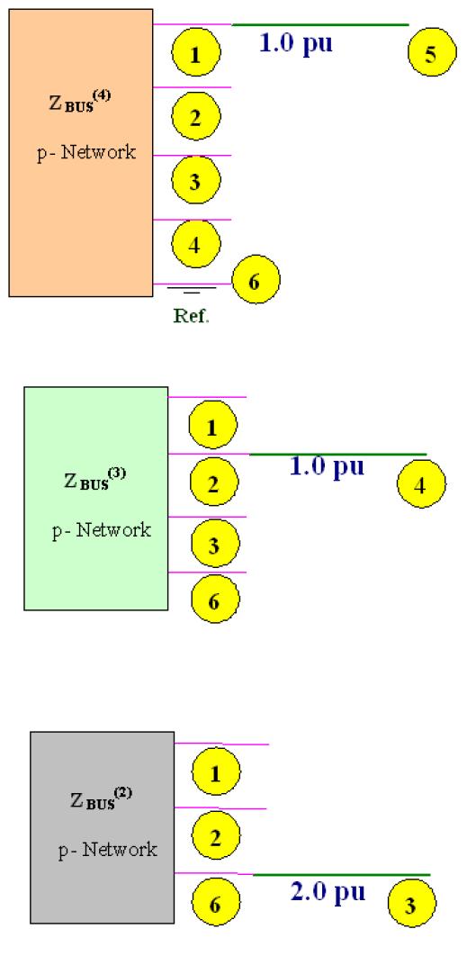
23 Fig. E1: Example System Consider building ZBUS as per the various stages of building through the consideration of the corresponding partial networks as under: Step-1: Add element 1 of impedance 0.25 pu from the external node-1 (q=1) to internal ref. node-0 (p=0). (Case-a), as shown in the partial network; Step-2: Add element 2 of impedance 0.2 pu from the external node-3 (q=3) to internal ref. node-0 (p=0). (Case-a), as shown in the partial network; Page 44
24 Step-3: Add element 3 of impedance 0.08 pu from the external node-2 (q=2) to internal node- 1 (p=1). (Case-b), as shown in the partial network; Step-4: Add element 4 of impedance 0.06 pu between the two internal nodes, node-2 (p=2) to node-3 (q=3). (Case-d), as shown in the partial network; Page 45


25 The fictitious node l is eliminated further to arrive at the final impedance matrix as under: Page 46
26 Page 47
27 Page 48

 Step2: Add branch 2, between node 2 and reference node. (q = 2, p = 0).")
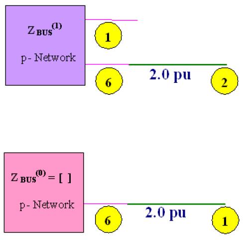
28 Solution: The specified system is considered with the reference node denoted by node-0. By its inspection, we can obtain the bus impedance matrix by building procedure by following the steps through the p-networks as under: Step1: Add branch 1 between node 1 and reference node. (q =1, p = 0) Step2: Add branch 2, between node 2 and reference node. (q = 2, p = 0). Page 49
 Step 4: Add")

29 Step3: Add branch 3, between node 1 and node 3 (p = 1, q = 3) Step 4: Add element 4, which is a link between node 1 and node 2. (p = 1, q = 2) Page 50
 Page")
30 Now the extra node-l has to be eliminated to obtain the new matrix of step-4, using the algorithmic relation: Step 5: Add link between node 2 and node 3 (p = 2, q=3) Page 51
31 Page 52
32 Expected questions: 1. Obtain the general expressions for Z bus building algorithm when a branch is added to the partial network. 2. For the network shown. Obtain the Ybus by singular transformation analysis. The line data is as follows 3. Obtain the general expressions for Z bus building algorithm when a link is added to the partial network. 4. Prepare the Z bus for the system shown using Z bus building algorithm 5. Prepare the Z bus for the system shown using Z bus building algorithm 6. Explain the formation of Z bus using Z bus building algorithm 7. What is a primitive network? Give the representation of a typical component and arrive at the performance equations both in impedance and admittance forms. Page 53
Power System Analysis
 Power System Analysis BY A. P U R N A C H A N D E R A S S I S T A N T P R O F E S S O R D E P A R T M E N T O F E E E A C E E N G I N E E R I N G C O L L E G E Course Objectives: 1. To understand and develop
INSTITUTE OF AERONAUTICAL ENGINEERING
 INSTITUTE OF AERONAUTICAL ENGINEERING (Autonomous) Dundigal, Hyderabad - 500 043 Department of Electrical and Electronics Engineering COMPUTER METHODS IN POWER SYSTEMS B.Tech III-II semester LECTURE NOTES
2 Power System Network Matrices I
 Power System Analysis Power System Network Matrices I. INRODUCION he various terms used in Graph heory are presented in this chapter. Formulation of different network matrices are discussed. Primitive
ELEC4612 Power System Analysis Power Flow Analysis
 ELEC462 Power Sstem Analsis Power Flow Analsis Dr Jaashri Ravishankar jaashri.ravishankar@unsw.edu.au Busbars The meeting point of various components of a PS is called bus. The bus or busbar is a conductor
2 NETWORK FORMULATION
 NTWRK FRMUATN NTRDUCTRY RMARKS For performing any power system studies on the digital computer, the first step is to construct a suitable mathematical model of the power system network The mathematical
4.3 Z BUS formation considering mutual coupling between elements
 4.3 Z BUS formation considering mutual coupling between elements Assume that the bus impedance matrix [ Z m BUS ] is known for a partial network of m nodes and a reference node. The bus voltage and bus
 Network Topology-2 & Dual and Duality Choice of independent branch currents and voltages: The solution of a network involves solving of all branch currents and voltages. We know that the branch current
EE 581 Power Systems. Admittance Matrix: Development, Direct and Iterative solutions
 EE 581 Power Systems Admittance Matrix: Development, Direct and Iterative solutions Overview and HW # 8 Chapter 2.4 Chapter 6.4 Chapter 6.1-6.3 Homework: Special Problem 1 and 2 (see handout) Overview
Power system model. Olof Samuelsson. EIEN15 Electric Power Systems L2
 Power system model Olof Samuelsson EIEN15 Electric Power Systems L2 1 Outline Previously: Models for lines, generator, power electronic converter, transformer Single line diagram Per unit Bus admittance
A Course Material on EE2351 POWER SYSTEM ANALYSIS
 A Course Material on EE2351 POWER SYSTEM ANALYSIS By Mrs. K. Umarani ASSISTANT PROFESSOR DEPARTMENT OF ELECTRICAL AND ELECTRONICS ENGINEERING SASURIE COLLEGE OF ENGINEERING VIJAYAMANGALAM 638 056 Page
INSTITUTE OF AERONAUTICAL ENGINEERING (Autonomous)
") INSTITUTE OF AERONAUTICAL ENGINEERING (Autonomous) Dundigal, Hyderabad - 500 043 ELECTRICAL AND ELECTRONICS ENGINEERING QUESTION BANK Course Name : Computer Methods in Power Systems Course Code : A60222
INSTITUTE OF AERONAUTICAL ENGINEERING (Autonomous) Dundigal, Hyderabad - 500 043 ELECTRICAL AND ELECTRONICS ENGINEERING QUESTION BANK Course Name : Computer Methods in Power Systems Course Code : A60222
COOKBOOK KVL AND KCL A COMPLETE GUIDE
 1250 COOKBOOK KVL AND KCL A COMPLETE GUIDE Example circuit: 1) Label all source and component values with a voltage drop measurement (+,- ) and a current flow measurement (arrow): By the passive sign convention,
Power system model. Olof Samuelsson. EIEN15 Electric Power Systems L2 1
 Power system model Olof Samuelsson 1 Outline Previously: Models for lines, generator, power electronic converter, transformer Single line diagram Per unit Bus admittance matrix Bus impedance matrix Thévenin
= V I = Bus Admittance Matrix. Chapter 6: Power Flow. Constructing Ybus. Example. Network Solution. Triangular factorization. Let
 Chapter 6: Power Flow Network Matrices Network Solutions Newton-Raphson Method Fast Decoupled Method Bus Admittance Matri Let I = vector of currents injected into nodes V = vector of node voltages Y bus
Notes for course EE1.1 Circuit Analysis TOPIC 10 2-PORT CIRCUITS
 Objectives: Introduction Notes for course EE1.1 Circuit Analysis 4-5 Re-examination of 1-port sub-circuits Admittance parameters for -port circuits TOPIC 1 -PORT CIRCUITS Gain and port impedance from -port
NETWORK CALCULATIONS updated 11/5/13 1:02 PM
 NETWORK CALCULATIONS updated 11/5/13 1:02 PM 11/5/13 Network Calcula2ons (c) 2013 H. Zmuda 1 Introductory Comments The typical power transmission network span a large geographic area and involve a large
Chapter 3. Loop and Cut-set Analysis
 Chapter 3. Loop and Cut-set Analysis By: FARHAD FARADJI, Ph.D. Assistant Professor, Electrical Engineering, K.N. Toosi University of Technology http://wp.kntu.ac.ir/faradji/electriccircuits2.htm References:
Electric Circuits I. Nodal Analysis. Dr. Firas Obeidat
 Electric Circuits I Nodal Analysis Dr. Firas Obeidat 1 Nodal Analysis Without Voltage Source Nodal analysis, which is based on a systematic application of Kirchhoff s current law (KCL). A node is defined
6. MESH ANALYSIS 6.1 INTRODUCTION
 6. MESH ANALYSIS INTRODUCTION PASSIVE SIGN CONVENTION PLANAR CIRCUITS FORMATION OF MESHES ANALYSIS OF A SIMPLE CIRCUIT DETERMINANT OF A MATRIX CRAMER S RULE GAUSSIAN ELIMINATION METHOD EXAMPLES FOR MESH
SECTION 5: POWER FLOW. ESE 470 Energy Distribution Systems
 SECTION 5: POWER FLOW ESE 470 Energy Distribution Systems 2 Introduction Nodal Analysis 3 Consider the following circuit Three voltage sources VV sss, VV sss, VV sss Generic branch impedances Could be
Chapter 9 Balanced Faults, Part II. 9.4 Systematic Fault Analysis Using Bus Impedance Matrix
 Chapter 9 Balanced Faults, Part II 9.4 Systematic Fault Analysis Using Bus Impedance Matrix In the previous analysis we employed the Thevenin model and ound the Thevenin voltage and impedance by means
Network Graphs and Tellegen s Theorem
 Networ Graphs and Tellegen s Theorem The concepts of a graph Cut sets and Kirchhoff s current laws Loops and Kirchhoff s voltage laws Tellegen s Theorem The concepts of a graph The analysis of a complex
CHAPTER 2 LOAD FLOW ANALYSIS FOR RADIAL DISTRIBUTION SYSTEM
 16 CHAPTER 2 LOAD FLOW ANALYSIS FOR RADIAL DISTRIBUTION SYSTEM 2.1 INTRODUCTION Load flow analysis of power system network is used to determine the steady state solution for a given set of bus loading
QUESTION BANK SUBJECT: NETWORK ANALYSIS (10ES34)
") QUESTION BANK SUBJECT: NETWORK ANALYSIS (10ES34) NOTE: FOR NUMERICAL PROBLEMS FOR ALL UNITS EXCEPT UNIT 5 REFER THE E-BOOK ENGINEERING CIRCUIT ANALYSIS, 7 th EDITION HAYT AND KIMMERLY. PAGE NUMBERS OF
QUESTION BANK SUBJECT: NETWORK ANALYSIS (10ES34) NOTE: FOR NUMERICAL PROBLEMS FOR ALL UNITS EXCEPT UNIT 5 REFER THE E-BOOK ENGINEERING CIRCUIT ANALYSIS, 7 th EDITION HAYT AND KIMMERLY. PAGE NUMBERS OF
Consider the following generalized simple circuit
 ntroduction to Circuit Analysis Getting Started We analyze circuits for several reasons Understand how they work Learn how to design from other people s work Debug our own designs Troubleshoot circuit
Module 2. DC Circuit. Version 2 EE IIT, Kharagpur
 Module 2 DC Circuit Lesson 5 Node-voltage analysis of resistive circuit in the context of dc voltages and currents Objectives To provide a powerful but simple circuit analysis tool based on Kirchhoff s
Notes for course EE1.1 Circuit Analysis TOPIC 4 NODAL ANALYSIS
 Notes for course EE1.1 Circuit Analysis 2004-05 TOPIC 4 NODAL ANALYSIS OBJECTIVES 1) To develop Nodal Analysis of Circuits without Voltage Sources 2) To develop Nodal Analysis of Circuits with Voltage
In this lecture, we will consider how to analyse an electrical circuit by applying KVL and KCL. As a result, we can predict the voltages and currents
 In this lecture, we will consider how to analyse an electrical circuit by applying KVL and KCL. As a result, we can predict the voltages and currents around an electrical circuit. This is a short lecture,
Massachusetts Institute of Technology Department of Electrical Engineering and Computer Science : Circuits & Electronics Problem Set #1 Solution
 Massachusetts Institute of Technology Department of Electrical Engineering and Computer Science 6.2: Circuits & Electronics Problem Set # Solution Exercise. The three resistors form a series connection.
mywbut.com Mesh Analysis
 Mesh Analysis 1 Objectives Meaning of circuit analysis; distinguish between the terms mesh and loop. To provide more general and powerful circuit analysis tool based on Kirchhoff s voltage law (KVL) only.
Writing Circuit Equations
 2 C H A P T E R Writing Circuit Equations Objectives By the end of this chapter, you should be able to do the following: 1. Find the complete solution of a circuit using the exhaustive, node, and mesh
ECE 1311: Electric Circuits. Chapter 2: Basic laws
 ECE 1311: Electric Circuits Chapter 2: Basic laws Basic Law Overview Ideal sources series and parallel Ohm s law Definitions open circuits, short circuits, conductance, nodes, branches, loops Kirchhoff's
Automatic Formulation of Circuit Equations
 ECE 570 Session 3 IC 752-E Computer Aided Engineering for Integrated Circuits Automatic Formulation of Circuit Equations Objective: Basics of computer aided analysis/simulation Outline:. Discussion of
Chapter 10 Sinusoidal Steady State Analysis Chapter Objectives:
 Chapter 10 Sinusoidal Steady State Analysis Chapter Objectives: Apply previously learn circuit techniques to sinusoidal steady-state analysis. Learn how to apply nodal and mesh analysis in the frequency
UNIT 4 DC EQUIVALENT CIRCUIT AND NETWORK THEOREMS
 UNIT 4 DC EQUIVALENT CIRCUIT AND NETWORK THEOREMS 1.0 Kirchoff s Law Kirchoff s Current Law (KCL) states at any junction in an electric circuit the total current flowing towards that junction is equal
QUIZ 1 SOLUTION. One way of labeling voltages and currents is shown below.
 F 14 1250 QUIZ 1 SOLUTION EX: Find the numerical value of v 2 in the circuit below. Show all work. SOL'N: One method of solution is to use Kirchhoff's and Ohm's laws. The first step in this approach is
Scattering Parameters
 Berkeley Scattering Parameters Prof. Ali M. Niknejad U.C. Berkeley Copyright c 2016 by Ali M. Niknejad September 7, 2017 1 / 57 Scattering Parameters 2 / 57 Scattering Matrix Voltages and currents are
CIRCUIT ANALYSIS TECHNIQUES
 APPENDI B CIRCUIT ANALSIS TECHNIQUES The following methods can be used to combine impedances to simplify the topology of an electric circuit. Also, formulae are given for voltage and current division across/through
PowerApps Optimal Power Flow Formulation
 PowerApps Optimal Power Flow Formulation Page1 Table of Contents 1 OPF Problem Statement... 3 1.1 Vector u... 3 1.1.1 Costs Associated with Vector [u] for Economic Dispatch... 4 1.1.2 Costs Associated
Relation of Pure Minimum Cost Flow Model to Linear Programming
 Appendix A Page 1 Relation of Pure Minimum Cost Flow Model to Linear Programming The Network Model The network pure minimum cost flow model has m nodes. The external flows given by the vector b with m
, and ignoring all load currents, determine
 ECE43 Test 3 Dec 8, 5 Q. (33 pts.) The Zbus for the above 3-bus network with bus as reference, in per unit, is given to be 3.87 j.798 j.8 j Z.798 j.87 j.8 j bus.8 j.8 j j Assuming that the prefault values
Chapter 2. Engr228 Circuit Analysis. Dr Curtis Nelson
 Chapter 2 Engr228 Circuit Analysis Dr Curtis Nelson Chapter 2 Objectives Understand symbols and behavior of the following circuit elements: Independent voltage and current sources; Dependent voltage and
4.1.3 Addition of a link between an existing node and the reference node (Case 3):
:") 4.1.3 Addition of a link between an existing node and the reference node (Case 3): When an element is connected between an existing node and the reference, it creates a loop and thus, the addition of this
4.1.3 Addition of a link between an existing node and the reference node (Case 3): When an element is connected between an existing node and the reference, it creates a loop and thus, the addition of this
7.6 The Inverse of a Square Matrix
 7.6 The Inverse of a Square Matrix Copyright Cengage Learning. All rights reserved. What You Should Learn Verify that two matrices are inverses of each other. Use Gauss-Jordan elimination to find inverses
NETWORK FORMULATION OF STRUCTURAL ANALYSIS
 Chapter 4 NETWORK FORMULATION OF STRUCTURAL ANALYSIS 4.1 INTRODUCTION Graph theoretical concepts have been widely employed for the analysis of networks in the field of electrical engineering. Kirchhoff
Chapter 4. Techniques of Circuit Analysis
 Chapter 4. Techniques of Circuit Analysis By: FARHAD FARADJI, Ph.D. Assistant Professor, Electrical Engineering, K.N. Toosi University of Technology http://wp.kntu.ac.ir/faradji/electriccircuits1.htm Reference:
Linear graph theory. Basic definitions of linear graphs
 Linear graph theory Linear graph theory, a branch of combinatorial mathematics has proved to be a useful tool for the study of large or complex systems. Leonhard Euler wrote perhaps the first paper on
Pre-Calculus I. For example, the system. x y 2 z. may be represented by the augmented matrix
 Pre-Calculus I 8.1 Matrix Solutions to Linear Systems A matrix is a rectangular array of elements. o An array is a systematic arrangement of numbers or symbols in rows and columns. Matrices (the plural
Chapter 2 Direct Current Circuits
 Chapter 2 Direct Current Circuits 2.1 Introduction Nowadays, our lives are increasingly dependent upon the availability of devices that make extensive use of electric circuits. The knowledge of the electrical
 TWO PORT NETWORKS Introduction: A port is normally referred to a pair of terminals of a network through which we can have access to network either for a source for measuring an output We have already seen
Propedeútico: Circuitos 2. Systematic Nodal Analysis. Dr. Arturo Sarmiento Reyes. INAOE Coordinación de Electrónica CA D Group. Mayo 16 Junio 10, 2016
 Propedeútico: Circuitos 2. Systematic Nodal Analysis Dr. Arturo Reyes INAOE Coordinación de Electrónica CA D Group Mayo 16 Junio 10, 2016 Dr. Arturo Reyes INAOE, Mayo, 2016 Propedeútico: Circuitos 2. Systematic
Power System Analysis Prof. A. K. Sinha Department of Electrical Engineering Indian Institute of Technology, Kharagpur. Lecture - 21 Power Flow VI
 Power System Analysis Prof. A. K. Sinha Department of Electrical Engineering Indian Institute of Technology, Kharagpur Lecture - 21 Power Flow VI (Refer Slide Time: 00:57) Welcome to lesson 21. In this
Basic. Theory. ircuit. Charles A. Desoer. Ernest S. Kuh. and. McGraw-Hill Book Company
 Basic C m ш ircuit Theory Charles A. Desoer and Ernest S. Kuh Department of Electrical Engineering and Computer Sciences University of California, Berkeley McGraw-Hill Book Company New York St. Louis San
EE 6501 POWER SYSTEMS UNIT I INTRODUCTION
 EE 6501 POWER SYSTEMS UNIT I INTRODUCTION PART A (2 MARKS) 1. What is single line diagram? A Single line diagram is diagrammatic representation of power system in which the components are represented by
AC Circuit Analysis and Measurement Lab Assignment 8
 Electric Circuit Lab Assignments elcirc_lab87.fm - 1 AC Circuit Analysis and Measurement Lab Assignment 8 Introduction When analyzing an electric circuit that contains reactive components, inductors and
Algebra & Trig. I. For example, the system. x y 2 z. may be represented by the augmented matrix
 Algebra & Trig. I 8.1 Matrix Solutions to Linear Systems A matrix is a rectangular array of elements. o An array is a systematic arrangement of numbers or symbols in rows and columns. Matrices (the plural
Module 2. DC Circuit. Version 2 EE IIT, Kharagpur
 Module DC Circuit Lesson 4 Loop Analysis of resistive circuit in the context of dc voltages and currents Objectives Meaning of circuit analysis; distinguish between the terms mesh and loop. To provide
A LOOP BASED LOAD FLOW METHOD FOR WEAKLY MESHED DISTRIBUTION NETWORK
 VOL. 3, NO. 4, AUGUST 28 ISSN 89-668 26-28 Asian Research Publishing Network (ARPN). All rights reserved. A LOOP BASED LOAD FLOW METHOD FOR WEAKLY MESHED S. Sivanagaraju, J. Viswanatha Rao 2 and M. Giridhar
DIRECTED GRAPH BASED POWER-FLOW ALGORITHM FOR 1-PHASE RDN
 method is used to formulate element-currents during the Forward-Sweep and the inclusion of power variable in the algorithm during Backward Sweep leads to more accurate results. The proposed TT based power-flow
Lecture Notes on DC Network Theory
 Federal University, Ndufu-Alike, Ikwo Department of Electrical/Electronics and Computer Engineering (ECE) Faculty of Engineering and Technology Lecture Notes on DC Network Theory Harmattan Semester by
A two-port network is an electrical network with two separate ports
 5.1 Introduction A two-port network is an electrical network with two separate ports for input and output. Fig(a) Single Port Network Fig(b) Two Port Network There are several reasons why we should study
Enhanced Newton Method Based Radial Distribution System Load Flow Analysis with Extrapolation Techniques
 Enhanced Newton Method Based Radial Distribution System Load Flow Analysis with Extrapolation Techniques Asst. Prof. Dr. Hassan Kuhba Electrical Engineering Department, Engineering College/Baghdad University,
THERE MUST BE 50 WAYS TO FIND YOUR VALUES: AN EXPLORATION OF CIRCUIT ANALYSIS TECHNIQUES FROM OHM S LAW TO EQUIVALENT CIRCUITS
 THERE MUST BE 50 WAYS TO FIND YOUR VALUES: AN EXPLORATION OF CIRCUIT ANALYSIS TECHNIQUES FROM OHM S LAW TO EQUIVALENT CIRCUITS Kristine McCarthy Josh Pratti Alexis Rodriguez-Carlson November 20, 2006 Table
4.10 Unbalanced fault analysis using Z BUS matrix:
 4.10 Unbalanced fault analysis using Z BUS matrix: In the previous section, it is observed that, for fault calculations the Thevenin s equivalent networs, at the fault point, are needed for the three sequence
Electric Circuit Theory
 Electric Circuit Theory Nam Ki Min nkmin@korea.ac.kr 010-9419-2320 Chapter 18 Two-Port Circuits Nam Ki Min nkmin@korea.ac.kr 010-9419-2320 Contents and Objectives 3 Chapter Contents 18.1 The Terminal Equations
09-Circuit Theorems Text: , 4.8. ECEGR 210 Electric Circuits I
 09Circuit Theorems Text: 4.1 4.3, 4.8 ECEGR 210 Electric Circuits I Overview Introduction Linearity Superposition Maximum Power Transfer Dr. Louie 2 Introduction Nodal and mesh analysis can be tedious
Lecture #3. Review: Power
 Lecture #3 OUTLINE Power calculations Circuit elements Voltage and current sources Electrical resistance (Ohm s law) Kirchhoff s laws Reading Chapter 2 Lecture 3, Slide 1 Review: Power If an element is
Sinusoidal Steady State Analysis (AC Analysis) Part I
 Part I") Sinusoidal Steady State Analysis (AC Analysis) Part I Amin Electronics and Electrical Communications Engineering Department (EECE) Cairo University elc.n102.eng@gmail.com http://scholar.cu.edu.eg/refky/
Sinusoidal Steady State Analysis (AC Analysis) Part I Amin Electronics and Electrical Communications Engineering Department (EECE) Cairo University elc.n102.eng@gmail.com http://scholar.cu.edu.eg/refky/
11 a 12 a 13 a 21 a 22 a b 12 b 13 b 21 b 22 b b 11 a 12 + b 12 a 13 + b 13 a 21 + b 21 a 22 + b 22 a 23 + b 23
 Chapter 2 (3 3) Matrices The methods used described in the previous chapter for solving sets of linear equations are equally applicable to 3 3 matrices. The algebra becomes more drawn out for larger matrices,
Identification of Electrical Circuits for Realization of Sparsity Preserving Reduced Order Models
 Identification of Electrical Circuits for Realization of Sparsity Preserving Reduced Order Models Christof Kaufmann 25th March 2010 Abstract Nowadays very-large scale integrated circuits contain a large
JUST THE MATHS SLIDES NUMBER 9.3. MATRICES 3 (Matrix inversion & simultaneous equations) A.J.Hobson
 A.J.Hobson") JUST THE MATHS SLIDES NUMBER 93 MATRICES 3 (Matrix inversion & simultaneous equations) by AJHobson 93 Introduction 932 Matrix representation of simultaneous linear equations 933 The definition of a multiplicative
JUST THE MATHS SLIDES NUMBER 93 MATRICES 3 (Matrix inversion & simultaneous equations) by AJHobson 93 Introduction 932 Matrix representation of simultaneous linear equations 933 The definition of a multiplicative
D C Circuit Analysis and Network Theorems:
 UNIT-1 D C Circuit Analysis and Network Theorems: Circuit Concepts: Concepts of network, Active and passive elements, voltage and current sources, source transformation, unilateral and bilateral elements,
Equivalent relaxations of optimal power flow
 Equivalent relaxations of optimal power flow 1 Subhonmesh Bose 1, Steven H. Low 2,1, Thanchanok Teeraratkul 1, Babak Hassibi 1 1 Electrical Engineering, 2 Computational and Mathematical Sciences California
BFF1303: ELECTRICAL / ELECTRONICS ENGINEERING. Alternating Current Circuits : Basic Law
 BFF1303: ELECTRICAL / ELECTRONICS ENGINEERING Alternating Current Circuits : Basic Law Ismail Mohd Khairuddin, Zulkifil Md Yusof Faculty of Manufacturing Engineering Universiti Malaysia Pahang Alternating
State Estimation and Power Flow Analysis of Power Systems
 JOURNAL OF COMPUTERS, VOL. 7, NO. 3, MARCH 01 685 State Estimation and Power Flow Analysis of Power Systems Jiaxiong Chen University of Kentucky, Lexington, Kentucky 40508 U.S.A. Email: jch@g.uky.edu Yuan
Lecture 3 BRANCHES AND NODES
 Lecture 3 Definitions: Circuits, Nodes, Branches Kirchoff s Voltage Law (KVL) Kirchoff s Current Law (KCL) Examples and generalizations RC Circuit Solution 1 Branch: BRANCHES AND NODES elements connected
Designing Information Devices and Systems I Spring 2018 Lecture Notes Note 11
 EECS 16A Designing Information Devices and Systems I Spring 2018 Lecture Notes Note 11 11.1 Context Our ultimate goal is to design systems that solve people s problems. To do so, it s critical to understand
Solution: Based on the slope of q(t): 20 A for 0 t 1 s dt = 0 for 3 t 4 s. 20 A for 4 t 5 s 0 for t 5 s 20 C. t (s) 20 C. i (A) Fig. P1.
: 20 A for 0 t 1 s dt = 0 for 3 t 4 s. 20 A for 4 t 5 s 0 for t 5 s 20 C. t (s) 20 C. i (A) Fig. P1.") Problem 1.24 The plot in Fig. P1.24 displays the cumulative charge q(t) that has entered a certain device up to time t. Sketch a plot of the corresponding current i(t). q 20 C 0 1 2 3 4 5 t (s) 20 C Figure
Problem 1.24 The plot in Fig. P1.24 displays the cumulative charge q(t) that has entered a certain device up to time t. Sketch a plot of the corresponding current i(t). q 20 C 0 1 2 3 4 5 t (s) 20 C Figure
Section 9.2: Matrices. Definition: A matrix A consists of a rectangular array of numbers, or elements, arranged in m rows and n columns.
 Section 9.2: Matrices Definition: A matrix A consists of a rectangular array of numbers, or elements, arranged in m rows and n columns. That is, a 11 a 12 a 1n a 21 a 22 a 2n A =...... a m1 a m2 a mn A
Module 3 : Sequence Components and Fault Analysis
 Module 3 : Sequence Components and Fault Analysis Lecture 12 : Sequence Modeling of Power Apparatus Objectives In this lecture we will discuss Per unit calculation and its advantages. Modeling aspects
Electric Circuits II Sinusoidal Steady State Analysis. Dr. Firas Obeidat
 Electric Circuits II Sinusoidal Steady State Analysis Dr. Firas Obeidat 1 Table of Contents 1 2 3 4 5 Nodal Analysis Mesh Analysis Superposition Theorem Source Transformation Thevenin and Norton Equivalent
The Effects of Mutual Coupling and Transformer Connection Type on Frequency Response of Unbalanced Three Phases Electrical Distribution System
 IJSRD - International Journal for Scientific Research & Development Vol. 1, Issue 9, 2013 ISSN (online): 2321-0613 The Effects of Mutual Coupling and Transformer Connection Type on Frequency Response of
AMS 209, Fall 2015 Final Project Type A Numerical Linear Algebra: Gaussian Elimination with Pivoting for Solving Linear Systems
 AMS 209, Fall 205 Final Project Type A Numerical Linear Algebra: Gaussian Elimination with Pivoting for Solving Linear Systems. Overview We are interested in solving a well-defined linear system given
CHAPTER 6 STEADY-STATE ANALYSIS OF SINGLE-PHASE SELF-EXCITED INDUCTION GENERATORS
 79 CHAPTER 6 STEADY-STATE ANALYSIS OF SINGLE-PHASE SELF-EXCITED INDUCTION GENERATORS 6.. INTRODUCTION The steady-state analysis of six-phase and three-phase self-excited induction generators has been presented
Comparison of Power Flow Algorithms for inclusion in On-line Power Systems Operation Tools
 University of New Orleans ScholarWorks@UNO University of New Orleans Theses and Dissertations Dissertations and Theses 12-17-2010 Comparison of Power Flow Algorithms for inclusion in On-line Power Systems
CHAPTER 2 CAPACITANCE REQUIREMENTS OF SIX-PHASE SELF-EXCITED INDUCTION GENERATORS
 9 CHAPTER 2 CAPACITANCE REQUIREMENTS OF SIX-PHASE SELF-EXCITED INDUCTION GENERATORS 2.. INTRODUCTION Rapidly depleting rate of conventional energy sources, has led the scientists to explore the possibility
Two-Layer Network Equivalent for Electromagnetic Transients
 1328 IEEE TRANSACTIONS ON POWER DELIVERY, VOL. 18, NO. 4, OCTOBER 2003 Two-Layer Network Equivalent for Electromagnetic Transients Mohamed Abdel-Rahman, Member, IEEE, Adam Semlyen, Life Fellow, IEEE, and
DC STEADY STATE CIRCUIT ANALYSIS
 DC STEADY STATE CIRCUIT ANALYSIS 1. Introduction The basic quantities in electric circuits are current, voltage and resistance. They are related with Ohm s law. For a passive branch the current is: I=
Introduction to Simulation - Lecture 2. Equation Formulation Methods. Jacob White. Thanks to Deepak Ramaswamy, Michal Rewienski, and Karen Veroy
 Introduction to Simulation - Lecture Equation Formulation Methods Jacob White Thanks to Deepak Ramaswamy, Michal Rewienski, and Karen Veroy Outline Formulating Equations rom Schematics Struts and Joints
MAC Module 2 Systems of Linear Equations and Matrices II. Learning Objectives. Upon completing this module, you should be able to :
 MAC 0 Module Systems of Linear Equations and Matrices II Learning Objectives Upon completing this module, you should be able to :. Find the inverse of a square matrix.. Determine whether a matrix is invertible..
B.E. / B.Tech. Degree Examination, April / May 2010 Sixth Semester. Electrical and Electronics Engineering. EE 1352 Power System Analysis
 B.E. / B.Tech. Degree Examination, April / May 2010 Sixth Semester Electrical and Electronics Engineering EE 1352 Power System Analysis (Regulation 2008) Time: Three hours Answer all questions Part A (10
Basic Concepts of Graph Theory Cut-set Incidence Matrix Circuit Matrix Cut-set Matrix
 Basic Concepts of Graph Theory Cut-set Incidence Matrix Circuit Matrix Cut-set Matrix Definition of Graph Definition: In a connected graph G of n nodes (vertices),the subgraph T that satisfies the following
The word Matrices is the plural of the word Matrix. A matrix is a rectangular arrangement (or array) of numbers called elements.
 of numbers called elements.") Numeracy Matrices Definition The word Matrices is the plural of the word Matrix A matrix is a rectangular arrangement (or array) of numbers called elements A x 3 matrix can be represented as below Matrix
Numeracy Matrices Definition The word Matrices is the plural of the word Matrix A matrix is a rectangular arrangement (or array) of numbers called elements A x 3 matrix can be represented as below Matrix
Kirchhoff's Laws and Circuit Analysis (EC 2)
") Kirchhoff's Laws and Circuit Analysis (EC ) Circuit analysis: solving for I and V at each element Linear circuits: involve resistors, capacitors, inductors Initial analysis uses only resistors Power sources,
Kirchhoff's Laws and Circuit Analysis (EC ) Circuit analysis: solving for I and V at each element Linear circuits: involve resistors, capacitors, inductors Initial analysis uses only resistors Power sources,
JUST THE MATHS UNIT NUMBER 9.3. MATRICES 3 (Matrix inversion & simultaneous equations) A.J.Hobson
 A.J.Hobson") JUST THE MATHS UNIT NUMBER 93 MATRICES 3 (Matrix inversion & simultaneous equations) by AJHobson 931 Introduction 932 Matrix representation of simultaneous linear equations 933 The definition of a multiplicative
JUST THE MATHS UNIT NUMBER 93 MATRICES 3 (Matrix inversion & simultaneous equations) by AJHobson 931 Introduction 932 Matrix representation of simultaneous linear equations 933 The definition of a multiplicative
NETWORK THEORY (BEES2211)
") LECTURE NOTES On NETWORK THEORY (BEES2211) 3 rd Semester ETC Engineering Prepared by, Manjushree Jena Jemimah Digal Monalisha Nayak INDIRA GANDHI INSTITUTE OF TECHNOLOGY, SARANG NETWORK THEORY Ms. Manjushree
LECTURE NOTES On NETWORK THEORY (BEES2211) 3 rd Semester ETC Engineering Prepared by, Manjushree Jena Jemimah Digal Monalisha Nayak INDIRA GANDHI INSTITUTE OF TECHNOLOGY, SARANG NETWORK THEORY Ms. Manjushree
MA 138 Calculus 2 with Life Science Applications Matrices (Section 9.2)
") MA 38 Calculus 2 with Life Science Applications Matrices (Section 92) Alberto Corso albertocorso@ukyedu Department of Mathematics University of Kentucky Friday, March 3, 207 Identity Matrix and Inverse
MA 38 Calculus 2 with Life Science Applications Matrices (Section 92) Alberto Corso albertocorso@ukyedu Department of Mathematics University of Kentucky Friday, March 3, 207 Identity Matrix and Inverse
Delhi Noida Bhopal Hyderabad Jaipur Lucknow Indore Pune Bhubaneswar Kolkata Patna Web: Ph:
 Serial : CH_EE_B_Network Theory_098 Delhi Noida Bhopal Hyderabad Jaipur Lucknow ndore Pune Bhubaneswar Kolkata Patna Web: E-mail: info@madeeasy.in Ph: 0-56 CLASS TEST 08-9 ELECTCAL ENGNEENG Subject : Network
Circuit Theory I Basic Laws
 Circuit Theory I Basic Laws Assistant Professor Suna BOLAT Eastern Mediterranean University Electric and electronic department ef2: Anant Agarwaland Jeffrey Lang, course materials for 6.002 Circuits and
ECE Linear Circuit Analysis II
 ECE 202 - Linear Circuit Analyi II Final Exam Solution December 9, 2008 Solution Breaking F into partial fraction, F 2 9 9 + + 35 9 ft δt + [ + 35e 9t ]ut A 9 Hence 3 i the correct anwer. Solution 2 ft