, N U No TORSIOI_AL S _TP_ENG_'w OF N!oKEL,4 STEEL AND DURALU}_iN TUBING. AS AFFECTED BY THE RATIO OF DIA}:_ETER TO CCaGE THICKNESS.
|
|
|
- Cuthbert Andrews
- 5 years ago
- Views:
Transcription
1 ,,-, j - X, N U i i u, TECHNICAL NOTES NATIONAL _- o - ADv IoORY CO_,_{ITTEE FOR AERONAUTICS. cas COp.y LE: No. 189 TORSIOI_AL S _TP_ENG_'w OF N!oKEL,4 STEEL AND DURALU}_iN TUBING AS AFFECTED BY THE RATIO OF DIA}:_ETER TO CCaGE THICKNESS. By N. S. Otey_ U,S, Naval Aircraft Factory " flc,o:,-:, _ To b_ re,turr_cl to the fl}ss of'the ]','._tion_.} Advisory Ce':nmitt_. or A_ronautics 1, April) Washin_to% D, O.
2 J NATIONAL ADVISORY C01_ITTEE FOR AERONAUTICS. TECHNICAL NOTE NO TORSIONAL STRENGTH OF NICKEL STEEL AND DURALUMIN TUBING AS AFFECTED BY THE RATIO OF DIA_TER TO GAGE THICKNESS.*_ By N. S. 0tey.! Introduction. This investigation was made at the request of the Bureau of Aeronautics. Since the ordinary torsion formula is based on elastic resistance to deformation, it is inaccurate for determination of ultimate stresses in thin wall tubing subjected to torsional loads. It has been found that the torsional modulus of rupture varies with the ratio of diameter to gage thickness and the object of these tests was to determine the extent of these variations fo_: subject materials. This Ss somewhat of a prorogation of wot.k** done by the Army Air Service at NcCook Field. Conclusions. I. The torsional modulus of rupture of nickel steel (2ZS0) and duralumin tubing varies with the ratio of diameter to gage thickness (D/t) as follows: (a) Nickel steel heat-treated for 125,000 Psi ultimate tensile strength. * Originally prepared as Report No. 6T2.Z-5, U. S Naval Aircraft Factory. * Air Service Information Circular No. 26Z, Volume III, dated. July 20, 19_I.
3 - 2 - Zodulus of rupture (M) = 135,500 S/D/t d (b) Duralumin treated for 55,000 Psi. ultimate tensile strength. Modulus of rupture (M) _-=- -v Mater ials. 2. The steel tubing used in this investigation was taken from stock having the following specified analysis" The heat treatment given this tubing was that of quenching in oil at 15B5 F. and drawing at 800 to ilo0 F. depending on the brinell hardness after quenching. 3. The duralumin tubing was standard stock material and since it had been heat-treated by the manufacturer, no further treatment was given. The specified chemical analysis is" _,ofe. Si.. Ca.,, ] l ' 9_ o !.o.e.4 '}.4 Max. tltax. I IvIax. iin. I!
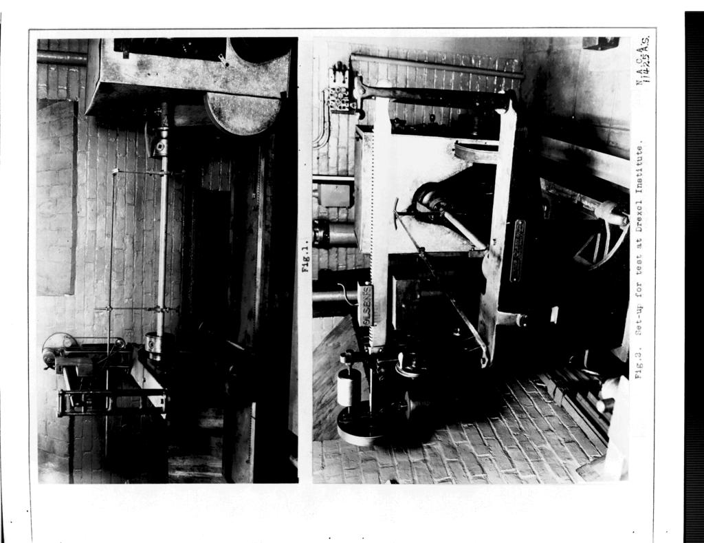
4 - 3 - procedure. 4. Twelve steel and ten duralumin tubes of diameters and gages shown in Table I were supplied in 60-inch lengths. From each ot these a 13-inch specimen was cut for tensile tests and the 48-inch lengths used for torsion tests. In the case of i steel, the tensile specimens had to be cut before heat _reatment due to size of furnace available, which, through heat treatment, resulted in variations in physical properties of the tensile and torsion specimen_:as will be shown later. The torsion specimens were tested in an 01sen torsion machine at Drexel Institute. The set-up used is shown in photographs (Figures I and 2_). Data. 5. Complete results of these tests are shown in Table I and Figures 8 to 15 inclusive. 8., The curves in Fioomres 5 and 8 show graphically the changes in moduli of rupture as affected by the D/t ratio. These curves were plotted under the following procedure: (a) Average curves were dravrn through the empirical points for convenience in obtaining the final curves. (b)] Values taken from these average curves were plotted to 10g scale as sho_rn in Figure 7, from which the slope of the average curves was determined.
5 - 4- (c) Using the slopes thus determined, equations were found from which the final curves shown on Figures 5 and 6 were plotted. These final curves were found to agree very favorably with the original average curves. 7. In Figures 8 to 15 inclusive, the torsional load/ deformation data is plotted. Curve Gi, (Fig. 13), shows irregularities in the region of the yield point which is characteristic of duralumin. 8. Photographs (Figures 3 and 4) show torsion specimens after test. It will be noted that in all cases but three, failure occurred by buckling or collapsing rather than shear, Discussion. 9. In the Case of the steel tubing, it will be noted that the empirical values are erratic as shown in Figure 5, This may be due to two causes" (a) Variations in physical properties of the material. (b)' Failure by crinkling or collapsing rather than shear. The first cause is not considered entirely responsible as examination of brinell hardness and moduli of rupture of the torsion specimens indicate more uniform physical properties than the tensile values shown in Table I, would suggest. AT-.. though the tensile and torsion specimens were heat-treated in
6 the same furnace and at the same time_ their differences in size likely caused considerable variations in physical properties. _Yith due consideration for. these erratic Tesults and their causes, the curve is considered sufficiently accurate for reliable desi_m data. _.,_uchcredit is due Drexel Institute for courtesies extended in permitting the use of their torsion testing equipment and for generous aid in conducting these tests,
7 - 6- Table I. STEEl: _TT_ T ]\'[_-, T e n s i 1 e P r o p e r t i e s.,_ No. Size Stress Stress E!ong. Psi 2" AI 1.000" W.038"Oa A2!,000 x BI ].,250 x ] B2!.250 x Cl x ,5 C x, D1!. 500 x D2!. 500 x.] I0.0 E ,065 ' I0.0 EPo i ,8700 I I0.3 i FI x,084 : ,, 10.8 F l DURALU_,_IN TUBING Gl B7.5 G2 0,749 x.057 _ ,5 H1 0,998 x ,0 H x tl!,375 x, I_ ,5 Jl t.495 x ,4.0 J2 1,490 x.0_ ,6.0 K1 1,500 x, , 25,0 K2!,500 x, I Notes: I, J = polar moment of inertia. 2. c = distance from polar axis to extreme fiber or D/2. 3. Load P. limit is torque in inch pounds, 4. Ult. load is torque in inch _ounds to rupture. 5, Torsion formula is S x J/C : Pp where Pp = torque in inch pounds. o
8 Table I (Contd.) STEEL TUBING Torsional Properties. # No, Brinali D/t J C J/C Hardness A AS _2, B , B ,05,0703 0,625.1].24 Cl v?0,1245 0, C , D ,750 4:593 D ,3445 O E! I E2 ' I, 125,4737 FI F ! Shore DURALUMIN TUBING Hardness GI 30,0 ' , G O HI O, 499,074.9 H I[! 24, , I , J! J " , K _ K O
9 Table I (Cont.) STEEL TUBING To r sional Prop ert ics. Load at Load at _odulus Modulus No. P. Limit Rupture of Rupture of Rupture 1_. Lira. _at Ult. A1 _ s_125- _.Z A :3400 BI B u0_ 75_00R CI I1800 II C2 III D D E l E_ F ,$ I ] F S DUFuiLUMiN TUBING GI G HI O H _ } 2375 _ I ,900 Jl 2500 SO , J , 2950 t ' K ! KS ]
10

11 o
12 U.q2uoz%s oitsuo_ O00[8I gutqu_ IO_%s OC_[_ [ ':_T_ ot_ - o_ o_ ot o!! i _ I i... i... T... _ 0 _... "... r..._..._ i i, { _3 ' i_ ---- _0 ' '," _... : i... '_... _ ' t -- t- t _'_"="... ;... _... _-... _... _... _... io ', : i _,, : t t ' i _ :! t I i i '!,... T... t-... _...,i"... i " _i... -_... i ' t /_;/7i I " i I i I ' \' ' ---- = _ '-. _o_a:no _To uot%_anb2 _. i I " _$-ep ' %so-$o I o, i i! _-' t t I t I.: oooooi... ] " t-... '... [... i.,...r i... _-..."-r-... j ). if... l -_ r... }t
13 f I t t i i I '! I-- T _.... i _... _... b...!... otest data "I i _ ' i, Equs.tion ' ' of curve t _ Equation points _! i! CO, i "V_I _ O000 _--t... _...!..._... _..._-... _... _...i... _... '_ " i ; " o _ i i! _< 0 : i!! cr.-_ "! i i""-_ : : _ " ) _...!... _... _... _... _...,_ ' _!,! _. 0 i :. -_ 1 _..' " _' _ t--' i-... _... :... _-...._.. 1 _ ['...,.'... -k" ----_ rj) :: _, " :. i _...'..._... I-...,...,...,... 0 _ i ;! ' I i I!,!,, i I 1 i ' ' i...i F... -t :-... _... r...!...! i i! i : i _, i ' i ' ; i I "_ _:- " -... " _ =- o _o _ o D/t... Fig. 6 Duralumin tubing _,,_ns_].e strength -.
14 _la L '_._,_ i! t, _ 9 _dols I O_ 0 i I O_ I_%$ 0{{_ E i ' uymui_-tn(i V - - _do18 i "xddv _ - = I i,!! i _ I ;! ' ' I i i { - i i I, 1 _ i f i i _ i t i i, i i i... OZ
15 Fig. S :! No. Gage Diam. AI.032,' I.0" A2.032" I.0" I 1 I t _ t... - t i "el I... I... _... _3ooo... i-_y----w-..._... i:?- o_2000, A 1 _, _ 9! _-I i, Y it _ i: Q o _d I i,!p.-' 0 I t... "i lo i-_... I " i! t Twist in degrees Fig. 8 Alloy steel tubing
16 _ i_... I l.., "-! t I! %J'-,.!! r-t i' _ ' : _! ' _,;td"l'_ n!,,! i ' i i H t, l._ o I ' - _ i! I i i - _ I ' i O'x O'x V_O I-'- _ 1._.-.d" r'_ Gt r-i.t'_... :..r-i spunod qou_ u; uo_szo_
17 Fig. i0
18 ,,.,,, t i 1 " 1 i! '! r"l _... --_ T _... _... T-'-- i (1) r--i "!!_! I _! : i _ i i _de. t CO= _/)OdOJ : "... j" "; i.r'l r_ r---ir-i _ ' _! ' t -t_ NA ' i J _--t 1, i o : o o o o o.o o o o _] _ _- c'j oj co r-.l _ spunod tlou! u! t_otszo_
19 Fig. 12 I i i i _-i ' r,.d ' " ' ' _ : : :.rh 0,-4 Cki,.--i t'm... :_ L... _,.0 i : b,.o-i-_ L "d_...,...,_._ I :. r-_ t " ' _ i! i i! i! I.±... I : i, J... i i : / t i i i I - _ ' 0... o o o o _ spuuod _ot_t ut uot_xo_ r_
20 vl i! _ i i! i I.,,is_,; ; _- _! ". ' [ -: _... i... _ I t, }! I : I i! i : I i _._ r_ ;! L... z..., = -- 0 L i i i " I t _ I i I d] 5Z} \i,.h _"_'_ i.r.r _... (-_i.- '... ;... I,_... -_... _,:... :... L _... :... _---.--_... _-_ ;--...:_--_ (I).r"l _..Q.h,-'I L _... i;... i -1...,,_ i... _ 'd b_l_ I'" ' ' i I " _',_ ooo,._l_l_ i [,.!. oh ' _,... i... _... }... i... i... _... i _.H ' l ; V JH_ ' : i i! ; i! L :... :... _...._... _r... ;... _..., } I I... i... ; I ij "-A "... "-+... _... L.. _... t _ i! i. _ i I!, I I i... } 1 i 1 I " o ,::) " O LP _ GI _.-_. _.0 i-.i tp_ i--t -t _ r-.t _ c.t _ H 0 i-t Ox to t_. ',.D._ r,_
21
22 Fig. 15
Experiment: Torsion Test Expected Duration: 1.25 Hours
 Course: Higher Diploma in Civil Engineering Unit: Structural Analysis I Experiment: Expected Duration: 1.25 Hours Objective: 1. To determine the shear modulus of the metal specimens. 2. To determine the
Structural Metals Lab 1.2. Torsion Testing of Structural Metals. Standards ASTM E143: Shear Modulus at Room Temperature
 Torsion Testing of Structural Metals Standards ASTM E143: Shear Modulus at Room Temperature Purpose To determine the shear modulus of structural metals Equipment Tinius-Olsen Lo-Torq Torsion Machine (figure
5. What is the moment of inertia about the x - x axis of the rectangular beam shown?
 1 of 5 Continuing Education Course #274 What Every Engineer Should Know About Structures Part D - Bending Strength Of Materials NOTE: The following question was revised on 15 August 2018 1. The moment
DEFLECTION OF BEAMS WlTH SPECIAL REFERENCE TO SHEAR DEFORMATIONS
 DEFLECTION OF BEAMS WlTH SPECIAL REFERENCE TO SHEAR DEFORMATIONS THE INFLUENCE OF THE FORM OF A WOODEN BEAM ON ITS STIFFNESS AND STRENGTH-I (REPRINT FROM NATIONAL ADVISORY COMMITTEE FOR AERONAUTICS REPORT
Stress Analysis Lecture 3 ME 276 Spring Dr./ Ahmed Mohamed Nagib Elmekawy
 Stress Analysis Lecture 3 ME 276 Spring 2017-2018 Dr./ Ahmed Mohamed Nagib Elmekawy Axial Stress 2 Beam under the action of two tensile forces 3 Beam under the action of two tensile forces 4 Shear Stress
ELASTIC STAIBILITY CIF TUE FACINGS Of HAT SANDWICI-1 PANELS WIASI SUBJECTED TO COMBINED EDGEWISE STRESSES
 ELASTIC STAIBILITY CIF TUE FACINGS Of HAT SANDWICI-1 PANELS WIASI SUBJECTED TO COMBINED EDGEWISE STRESSES Information Reviewed and Reaffirmed Aucust 1955 NFORMA-tiON RE'4,E\AE.'L; n PE.1-17;9';f2,. This!Report
Mechanical Engineering Ph.D. Preliminary Qualifying Examination Solid Mechanics February 25, 2002
 student personal identification (ID) number on each sheet. Do not write your name on any sheet. #1. A homogeneous, isotropic, linear elastic bar has rectangular cross sectional area A, modulus of elasticity
[7] Torsion. [7.1] Torsion. [7.2] Statically Indeterminate Torsion. [7] Torsion Page 1 of 21
![[7] Torsion. [7.1] Torsion. [7.2] Statically Indeterminate Torsion. [7] Torsion Page 1 of 21](/thumbs/88/115835122.jpg "[7] Torsion. [7.1] Torsion. [7.2] Statically Indeterminate Torsion. [7] Torsion Page 1 of 21") [7] Torsion Page 1 of 21 [7] Torsion [7.1] Torsion [7.2] Statically Indeterminate Torsion [7] Torsion Page 2 of 21 [7.1] Torsion SHEAR STRAIN DUE TO TORSION 1) A shaft with a circular cross section is
[7] Torsion Page 1 of 21 [7] Torsion [7.1] Torsion [7.2] Statically Indeterminate Torsion [7] Torsion Page 2 of 21 [7.1] Torsion SHEAR STRAIN DUE TO TORSION 1) A shaft with a circular cross section is
6.37 Determine the modulus of resilience for each of the following alloys:
 6.37 Determine the modulus of resilience for each of the following alloys: Yield Strength Material MPa psi Steel alloy 550 80,000 Brass alloy 350 50,750 Aluminum alloy 50 36,50 Titanium alloy 800 116,000
Stress Strain Elasticity Modulus Young s Modulus Shear Modulus Bulk Modulus. Case study
 Stress Strain Elasticity Modulus Young s Modulus Shear Modulus Bulk Modulus Case study 2 In field of Physics, it explains how an object deforms under an applied force Real rigid bodies are elastic we can
ME 243. Mechanics of Solids
 ME 243 Mechanics of Solids Lecture 2: Stress and Strain Ahmad Shahedi Shakil Lecturer, Dept. of Mechanical Engg, BUET E-mail: sshakil@me.buet.ac.bd, shakil6791@gmail.com Website: teacher.buet.ac.bd/sshakil
Stress-Strain Behavior
 Stress-Strain Behavior 6.3 A specimen of aluminum having a rectangular cross section 10 mm 1.7 mm (0.4 in. 0.5 in.) is pulled in tension with 35,500 N (8000 lb f ) force, producing only elastic deformation.
NAME: Given Formulae: Law of Cosines: Law of Sines:
 NME: Given Formulae: Law of Cosines: EXM 3 PST PROBLEMS (LESSONS 21 TO 28) 100 points Thursday, November 16, 2017, 7pm to 9:30, Room 200 You are allowed to use a calculator and drawing equipment, only.
High Tech High Top Hat Technicians. An Introduction to Solid Mechanics. Is that supposed to bend there?
 High Tech High Top Hat Technicians An Introduction to Solid Mechanics Or Is that supposed to bend there? Why don't we fall through the floor? The power of any Spring is in the same proportion with the
The science of elasticity
 The science of elasticity In 1676 Hooke realized that 1.Every kind of solid changes shape when a mechanical force acts on it. 2.It is this change of shape which enables the solid to supply the reaction
ME 2570 MECHANICS OF MATERIALS
 ME 2570 MECHANICS OF MATERIALS Chapter III. Mechanical Properties of Materials 1 Tension and Compression Test The strength of a material depends on its ability to sustain a load without undue deformation
BEAMS AND PLATES ANALYSIS
 BEAMS AND PLATES ANALYSIS Automotive body structure can be divided into two types: i. Frameworks constructed of beams ii. Panels Classical beam versus typical modern vehicle beam sections Assumptions:
Chapter Objectives. Copyright 2011 Pearson Education South Asia Pte Ltd
 Chapter Objectives To determine the torsional deformation of a perfectly elastic circular shaft. To determine the support reactions when these reactions cannot be determined solely from the moment equilibrium
Lab Exercise #3: Torsion
 Lab Exercise #3: Pre-lab assignment: Yes No Goals: 1. To evaluate the equations of angular displacement, shear stress, and shear strain for a shaft undergoing torsional stress. Principles: testing of round
Chapter 6: Mechanical Properties of Metals. Dr. Feras Fraige
 Chapter 6: Mechanical Properties of Metals Dr. Feras Fraige Stress and Strain Tension Compression Shear Torsion Elastic deformation Plastic Deformation Yield Strength Tensile Strength Ductility Toughness
Conceptual question Conceptual question 12.2
 Conceptual question 12.1 rigid cap of weight W t g r A thin-walled tank (having an inner radius of r and wall thickness t) constructed of a ductile material contains a gas with a pressure of p. A rigid
Lab Exercise #5: Tension and Bending with Strain Gages
 Lab Exercise #5: Tension and Bending with Strain Gages Pre-lab assignment: Yes No Goals: 1. To evaluate tension and bending stress models and Hooke s Law. a. σ = Mc/I and σ = P/A 2. To determine material
Mechanics of Materials II. Chapter III. A review of the fundamental formulation of stress, strain, and deflection
 Mechanics of Materials II Chapter III A review of the fundamental formulation of stress, strain, and deflection Outline Introduction Assumtions and limitations Axial loading Torsion of circular shafts
MECHANICS LAB AM 317 EXP 4 TORSION OF CIRCULAR RODS
 MECHANICS LAB AM 317 EXP 4 TORSION OF CIRCULAR RODS I. OBJECTIVES I.1 To become familiar with torsion tests of rods with solid circular cross sections. I.2 To observe the relation between shear stress
twenty one concrete construction: shear & deflection ARCHITECTURAL STRUCTURES: FORM, BEHAVIOR, AND DESIGN DR. ANNE NICHOLS SUMMER 2014 lecture
 ARCHITECTURAL STRUCTURES: FORM, BEHAVIOR, AND DESIGN DR. ANNE NICHOLS SUMMER 2014 lecture twenty one concrete construction: Copyright Kirk Martini shear & deflection Concrete Shear 1 Shear in Concrete
TORSION TEST. Figure 1 Schematic view of torsion test
 TORSION TEST 1. THE PURPOSE OF THE TEST The torsion test is performed for determining the properties of materials like shear modulus (G) and shear yield stress ( A ). 2. IDENTIFICATIONS: Shear modulus:
Lecture-04 Design of RC Members for Shear and Torsion
 Lecture-04 Design of RC Members for Shear and Torsion By: Prof. Dr. Qaisar Ali Civil Engineering Department UET Peshawar drqaisarali@uetpeshawar.edu.pk www.drqaisarali.com 1 Topics Addressed Design of
Chapter 5 Torsion STRUCTURAL MECHANICS: CE203. Notes are based on Mechanics of Materials: by R. C. Hibbeler, 7th Edition, Pearson
 STRUCTURAL MECHANICS: CE203 Chapter 5 Torsion Notes are based on Mechanics of Materials: by R. C. Hibbeler, 7th Edition, Pearson Dr B. Achour & Dr Eng. K. El-kashif Civil Engineering Department, University
MECHANICS OF MATERIALS. Prepared by Engr. John Paul Timola
 MECHANICS OF MATERIALS Prepared by Engr. John Paul Timola Mechanics of materials branch of mechanics that studies the internal effects of stress and strain in a solid body. stress is associated with the
DEPARTMENT OF MECHANICAL ENIGINEERING, UNIVERSITY OF ENGINEERING & TECHNOLOGY LAHORE (KSK CAMPUS).
.") DEPARTMENT OF MECHANICAL ENIGINEERING, UNIVERSITY OF ENGINEERING & TECHNOLOGY LAHORE (KSK CAMPUS). Lab Director: Coordinating Staff: Mr. Muhammad Farooq (Lecturer) Mr. Liaquat Qureshi (Lab Supervisor)
DEPARTMENT OF MECHANICAL ENIGINEERING, UNIVERSITY OF ENGINEERING & TECHNOLOGY LAHORE (KSK CAMPUS). Lab Director: Coordinating Staff: Mr. Muhammad Farooq (Lecturer) Mr. Liaquat Qureshi (Lab Supervisor)
National Exams May 2015
 National Exams May 2015 04-BS-6: Mechanics of Materials 3 hours duration Notes: If doubt exists as to the interpretation of any question, the candidate is urged to submit with the answer paper a clear
Outline. Tensile-Test Specimen and Machine. Stress-Strain Curve. Review of Mechanical Properties. Mechanical Behaviour
 Tensile-Test Specimen and Machine Review of Mechanical Properties Outline Tensile test True stress - true strain (flow curve) mechanical properties: - Resilience - Ductility - Toughness - Hardness A standard
SERVICEABILITY OF BEAMS AND ONE-WAY SLABS
 CHAPTER REINFORCED CONCRETE Reinforced Concrete Design A Fundamental Approach - Fifth Edition Fifth Edition SERVICEABILITY OF BEAMS AND ONE-WAY SLABS A. J. Clark School of Engineering Department of Civil
STANDARD SAMPLE. Reduced section " Diameter. Diameter. 2" Gauge length. Radius
 MATERIAL PROPERTIES TENSILE MEASUREMENT F l l 0 A 0 F STANDARD SAMPLE Reduced section 2 " 1 4 0.505" Diameter 3 4 " Diameter 2" Gauge length 3 8 " Radius TYPICAL APPARATUS Load cell Extensometer Specimen
APPENDIX 1 MODEL CALCULATION OF VARIOUS CODES
 163 APPENDIX 1 MODEL CALCULATION OF VARIOUS CODES A1.1 DESIGN AS PER NORTH AMERICAN SPECIFICATION OF COLD FORMED STEEL (AISI S100: 2007) 1. Based on Initiation of Yielding: Effective yield moment, M n
ri [11111 IlL DIRECTIONAL PROPERTIES Of GLASS-FABRIC-BASE PLASTIC LAMINATE PANELS Of SIZES THAT DO NOT IBUCICLE (P-Q1lAtVjr) No.
 No.") Supplement to DIRECTIONAL PROPERTIES Of GLASS-FABRIC-BASE PLASTIC LAMINATE PANELS Of SIZES THAT DO NOT IBUCICLE (P-Q1lAtVjr) No. 1803-13 November 1955 This Report is One of a Series issued hi Cooperation
Supplement to DIRECTIONAL PROPERTIES Of GLASS-FABRIC-BASE PLASTIC LAMINATE PANELS Of SIZES THAT DO NOT IBUCICLE (P-Q1lAtVjr) No. 1803-13 November 1955 This Report is One of a Series issued hi Cooperation
NORMAL STRESS. The simplest form of stress is normal stress/direct stress, which is the stress perpendicular to the surface on which it acts.
 NORMAL STRESS The simplest form of stress is normal stress/direct stress, which is the stress perpendicular to the surface on which it acts. σ = force/area = P/A where σ = the normal stress P = the centric
MECHANICS OF MATERIALS Sample Problem 4.2
 Sample Problem 4. SOLUTON: Based on the cross section geometry, calculate the location of the section centroid and moment of inertia. ya ( + Y Ad ) A A cast-iron machine part is acted upon by a kn-m couple.
Mechanical properties 1 Elastic behaviour of materials
 MME131: Lecture 13 Mechanical properties 1 Elastic behaviour of materials A. K. M. B. Rashid Professor, Department of MME BUET, Dhaka Today s Topics Deformation of material under the action of a mechanical
March No In Cooperation with the University of Wisconsin
 March 1956 No. In Cooperation with the University of Wisconsin STRESSES IN WOOD MEMBERS SUBJECTED TO COMBINED COLUMN AND BEAM ACTION.* J. A. NEWLIN and G. W. TRAYER. INTRODUCTION. This publication is one
Longitudinal strength standard
 (1989) (Rev. 1 199) (Rev. Nov. 001) Longitudinal strength standard.1 Application This requirement applies only to steel ships of length 90 m and greater in unrestricted service. For ships having one or
Tuesday, February 11, Chapter 3. Load and Stress Analysis. Dr. Mohammad Suliman Abuhaiba, PE
 1 Chapter 3 Load and Stress Analysis 2 Chapter Outline Equilibrium & Free-Body Diagrams Shear Force and Bending Moments in Beams Singularity Functions Stress Cartesian Stress Components Mohr s Circle for
1. Given the shown built-up tee-shape, determine the following for both strong- and weak-axis bending:
 1. Given the shown built-up tee-shape, determe the followg for both strong- and weak-ais bendg: a. Location of the neutral ais b. Moment of ertia c. Section Moduli d. Radius of gration Solution: (a) Location
Chapter 5: Torsion. 1. Torsional Deformation of a Circular Shaft 2. The Torsion Formula 3. Power Transmission 4. Angle of Twist CHAPTER OBJECTIVES
 CHAPTER OBJECTIVES Chapter 5: Torsion Discuss effects of applying torsional loading to a long straight member (shaft or tube) Determine stress distribution within the member under torsional load Determine
PDDC 1 st Semester Civil Engineering Department Assignments of Mechanics of Solids [ ] Introduction, Fundamentals of Statics
![PDDC 1 st Semester Civil Engineering Department Assignments of Mechanics of Solids [ ] Introduction, Fundamentals of Statics](/thumbs/92/109382806.jpg "PDDC 1 st Semester Civil Engineering Department Assignments of Mechanics of Solids [ ] Introduction, Fundamentals of Statics") Page1 PDDC 1 st Semester Civil Engineering Department Assignments of Mechanics of Solids [2910601] Introduction, Fundamentals of Statics 1. Differentiate between Scalar and Vector quantity. Write S.I.
Page1 PDDC 1 st Semester Civil Engineering Department Assignments of Mechanics of Solids [2910601] Introduction, Fundamentals of Statics 1. Differentiate between Scalar and Vector quantity. Write S.I.
Solid Mechanics Chapter 1: Tension, Compression and Shear
 Solid Mechanics Chapter 1: Tension, Compression and Shear Dr. Imran Latif Department of Civil and Environmental Engineering College of Engineering University of Nizwa (UoN) 1 Why do we study Mechanics
MECHANICS OF MATERIALS REVIEW
 MCHANICS OF MATRIALS RVIW Notation: - normal stress (psi or Pa) - shear stress (psi or Pa) - normal strain (in/in or m/m) - shearing strain (in/in or m/m) I - area moment of inertia (in 4 or m 4 ) J -
Unified Quiz M4 May 7, 2008 M - PORTION
 9:00-10: 00 (last four digits) 32-141 Unified Quiz M4 May 7, 2008 M - PORTION Put the last four digits of your MIT ID # on each page of the exam. Read all questions carefully. Do all work on that question
Mechanical Design in Optical Engineering
 Torsion Torsion: Torsion refers to the twisting of a structural member that is loaded by couples (torque) that produce rotation about the member s longitudinal axis. In other words, the member is loaded
Calculating the Risk of Structural Failure
 Calculating the Risk of Structural Failure Presentation at Society of Reliability Engineers Meeting December 9, 2015 Bob Graber STARGroup Solutions, LLC robert.graber@stargroup.solutions Designing a Structure
Towards The. Design of Super Columns. Prof. AbdulQader Najmi
 Towards The Design of Super Columns Prof. AbdulQader Najmi Description: Tubular Column Square or Round Filled with Concrete Provided with U-Links welded to its Walls as shown in Figure 1 Compression Specimen
Design of Steel Structures Prof. S.R.Satish Kumar and Prof. A.R.Santha Kumar
 5.4 Beams As stated previousl, the effect of local buckling should invariabl be taken into account in thin walled members, using methods described alread. Laterall stable beams are beams, which do not
Mechanical Properties of Materials
 Mechanical Properties of Materials Strains Material Model Stresses Learning objectives Understand the qualitative and quantitative description of mechanical properties of materials. Learn the logic of
1 of 12. Law of Sines: Stress = E = G. Deformation due to Temperature: Δ
 NAME: ES30 STRENGTH OF MATERIALS FINAL EXAM: FRIDAY, MAY 1 TH 4PM TO 7PM Closed book. Calculator and writing supplies allowed. Protractor and compass allowed. 180 Minute Time Limit GIVEN FORMULAE: Law
APPH 4200 Physics of Fluids
 APPH 42 Physics of Fluids Problem Solving and Vorticity (Ch. 5) 1.!! Quick Review 2.! Vorticity 3.! Kelvin s Theorem 4.! Examples 1 How to solve fluid problems? (Like those in textbook) Ç"Tt=l I $T1P#(
Shafts: Torsion of Circular Shafts Reading: Crandall, Dahl and Lardner 6.2, 6.3
 M9 Shafts: Torsion of Circular Shafts Reading: Crandall, Dahl and Lardner 6., 6.3 A shaft is a structural member which is long and slender and subject to a torque (moment) acting about its long axis. We
MECHANICS OF MATERIALS
 2009 The McGraw-Hill Companies, Inc. All rights reserved. Fifth SI Edition CHAPTER 3 MECHANICS OF MATERIALS Ferdinand P. Beer E. Russell Johnston, Jr. John T. DeWolf David F. Mazurek Torsion Lecture Notes:
Tensile stress strain curves for different materials. Shows in figure below
 Tensile stress strain curves for different materials. Shows in figure below Furthermore, the modulus of elasticity of several materials effected by increasing temperature, as is shown in Figure Asst. Lecturer
BME 207 Introduction to Biomechanics Spring 2017
 April 7, 2017 UNIVERSITY OF RHODE ISAND Department of Electrical, Computer and Biomedical Engineering BE 207 Introduction to Biomechanics Spring 2017 Homework 7 Problem 14.3 in the textbook. In addition
WORCESTER POLYTECHNIC INSTITUTE
 WORCESTER POLYTECHNIC INSTITUTE MECHANICAL ENGINEERING DEPARTMENT STRESS ANALYSIS ES-2502, C 2012 Lecture 17: 10 February 2012 General information Instructor: Cosme Furlong HL-151 (508) 831-5126 cfurlong@wpi.edu
EMA 3702 Mechanics & Materials Science (Mechanics of Materials) Chapter 3 Torsion
 Chapter 3 Torsion") EMA 3702 Mechanics & Materials Science (Mechanics of Materials) Chapter 3 Torsion Introduction Stress and strain in components subjected to torque T Circular Cross-section shape Material Shaft design Non-circular
EMA 3702 Mechanics & Materials Science (Mechanics of Materials) Chapter 3 Torsion Introduction Stress and strain in components subjected to torque T Circular Cross-section shape Material Shaft design Non-circular
Materials and Shape. Part 1: Materials for efficient structure. A. K. M. B. Rashid Professor, Department of MME BUET, Dhaka. Learning Objectives
 MME445: Lecture 27 Materials and Shape Part 1: Materials for efficient structure A. K. M. B. Rashid Professor, Department of MME BUET, Dhaka Learning Objectives Knowledge & Understanding Understand the
CIVL222 STRENGTH OF MATERIALS. Chapter 6. Torsion
 CIVL222 STRENGTH OF MATERIALS Chapter 6 Torsion Definition Torque is a moment that tends to twist a member about its longitudinal axis. Slender members subjected to a twisting load are said to be in torsion.
Fundamentals of Durability. Unrestricted Siemens AG 2013 All rights reserved. Siemens PLM Software
 Fundamentals of Durability Page 1 Your single provider of solutions System simulation solutions 3D simulation solutions Test-based engineering solutions Engineering services - Deployment services Troubleshooting
TORSION INCLUDING WARPING OF OPEN SECTIONS (I, C, Z, T AND L SHAPES)
") Page1 TORSION INCLUDING WARPING OF OPEN SECTIONS (I, C, Z, T AND L SHAPES) Restrained warping for the torsion of thin-wall open sections is not included in most commonly used frame analysis programs. Almost
Page1 TORSION INCLUDING WARPING OF OPEN SECTIONS (I, C, Z, T AND L SHAPES) Restrained warping for the torsion of thin-wall open sections is not included in most commonly used frame analysis programs. Almost
1 of 7. Law of Sines: Stress = E = G. Deformation due to Temperature: Δ
 NME: ES30 STRENGTH OF MTERILS FINL EXM: FRIDY, MY 1 TH 4PM TO 7PM Closed book. Calculator and writing supplies allowed. Protractor and compass allowed. 180 Minute Time Limit GIVEN FORMULE: Law of Cosines:
Shafts. Fig.(4.1) Dr. Salah Gasim Ahmed YIC 1
 Dr. Salah Gasim Ahmed YIC 1") Shafts. Power transmission shafting Continuous mechanical power is usually transmitted along and etween rotating shafts. The transfer etween shafts is accomplished y gears, elts, chains or other similar
Shafts. Power transmission shafting Continuous mechanical power is usually transmitted along and etween rotating shafts. The transfer etween shafts is accomplished y gears, elts, chains or other similar
P a g e 5 1 of R e p o r t P B 4 / 0 9
 P a g e 5 1 of R e p o r t P B 4 / 0 9 J A R T a l s o c o n c l u d e d t h a t a l t h o u g h t h e i n t e n t o f N e l s o n s r e h a b i l i t a t i o n p l a n i s t o e n h a n c e c o n n e
Date Submitted: 1/8/13 Section #4: T Instructor: Morgan DeLuca. Abstract
 Lab Report #2: Poisson s Ratio Name: Sarah Brown Date Submitted: 1/8/13 Section #4: T 10-12 Instructor: Morgan DeLuca Group Members: 1. Maura Chmielowiec 2. Travis Newberry 3. Thomas Cannon Title: Poisson
DESCRIBING THE PLASTIC DEFORMATION OF ALUMINUM SOFTBALL BATS
 DESCRIBING THE PLASTIC DEFORMATION OF ALUMINUM SOFTBALL BATS E. BIESEN 1 AND L. V. SMITH 2 Washington State University, 201 Sloan, Spokane St, Pullman, WA 99164-2920 USA 1 E-mail: ebiesen@gonzaga.edu 2
MAAE 2202 A. Come to the PASS workshop with your mock exam complete. During the workshop you can work with other students to review your work.
 It is most beneficial to you to write this mock final exam UNDER EXAM CONDITIONS. This means: Complete the exam in 3 hours. Work on your own. Keep your textbook closed. Attempt every question. After the
Cyby TISIA E. Document No. - "/r ".. TECHNICAL LIBRARY /, Copy No. /- ' E. E. Secher. 2 uut15. No. EM JReport
 .All I( l-, ltc I+ / '" TECHNICAL LIBRARY /, Document No. - "/r ".. Copy No. /- ' Cyby E. E. Secher " ~~ ~ ~~ A I P"l +" ".i JReport No. EM 9-18 2 uut15 H.ARD MIfROFICHE COPY $o 6. - S PA CE 1NO TEC- LO.aQG3Y
How materials work. Compression Tension Bending Torsion
 Materials How materials work Compression Tension Bending Torsion Elemental material atoms: A. Composition a) Nucleus: protons (+), neutrons (0) b) Electrons (-) B. Neutral charge, i.e., # electrons = #
CHAPTER 2 COMPOUND BARS. Summary. F1 =- L1 w. c- L
 CHAPTER 2 COMPOUND BARS Summary When a compound bar is constructed from members of different materials, lengths and areas and is subjected to an external tensile or compressive load W the load carried
A Study on the Tube of Integral Propeller Shaft for the Rear-wheel Drive Automobile Using Carbon Composite Fiber
 A Study on the Tube of Integral Propeller Shaft for the Rear-wheel Drive Automobile Using Carbon Composite Fiber Kibong Han Mechatronics Department, Jungwon University, 85 Munmu-ro, Goesan-gun, South Korea.
WRINI CLING Of THE FACINGS OF SANDWICH CONSTRUCTION %EJECTED TO EDGEWISE COMPRESSION Sandwich Constructions Having Honeycomb Cores
 WRINI CLING Of THE FACINGS OF SANDWICH CONSTRUCTION %EJECTED TO EDGEWISE COMPRESSION Sandwich Constructions Having Honeycomb Cores June 1953 This Report is One of a Series Issued in Cooperation with the
RESEARCH PROJECT NO. 26
 RESEARCH PROJECT NO. 26 DETERMINATION OF POISSON'S RATIO IN ADI TESTING BY UNIVERSITY OF MICHIGAN REPORT PREPARED BY BELA V. KOVACS and JOHN R. KEOUGH DUCTILE IRON SOCIETY Issued by the Ductile Iron Society
Structural Analysis I Chapter 4 - Torsion TORSION
 ORSION orsional stress results from the action of torsional or twisting moments acting about the longitudinal axis of a shaft. he effect of the application of a torsional moment, combined with appropriate
Module 7 Design of Springs. Version 2 ME, IIT Kharagpur
 Module 7 Design of Springs Lesson 1 Introduction to Design of Helical Springs Instructional Objectives: At the end of this lesson, the students should be able to understand: Uses of springs Nomenclature
The University of Texas at Austin
 r The University of Texas at Austin College of Engineering COEFFICIENT OF THERMAL EXPANSION FOR FOUR BATCH DESIGNS AND ONE SOLID GRANITE SPECIMEN by A Report Prepared for FOSTER YEOMAN LIMITED by the CENTER
N = N A Pb A Pb. = ln N Q v kt. = kt ln v N
 5. Calculate the energy for vacancy formation in silver, given that the equilibrium number of vacancies at 800 C (1073 K) is 3.6 10 3 m 3. The atomic weight and density (at 800 C) for silver are, respectively,
STRENGTH AND STIFFNESS REDUCTION OF LARGE NOTCHED BEAMS
 STRENGTH AND STIFFNESS REDUCTION OF LARGE NOTCHED BEAMS By Joseph F. Murphy 1 ABSTRACT: Four large glulam beams with notches on the tension side were tested for strength and stiffness. Using either bending
MIL-HDBK-5H 1 December 1998
 components are calculated. In some cases, the methods presented are empirical and subject to further refinements. Any further expansion of information on element behavior in MIL-HDBK-5 will emphasize those
MODULE C: COMPRESSION MEMBERS
 MODULE C: COMPRESSION MEMBERS This module of CIE 428 covers the following subjects Column theory Column design per AISC Effective length Torsional and flexural-torsional buckling Built-up members READING:
Using the Rational Root Theorem to Find Real and Imaginary Roots Real roots can be one of two types: ra...-\; 0 or - l (- - ONLl --
 Using the Rational Root Theorem to Find Real and Imaginary Roots Real roots can be one of two types: ra...-\; 0 or - l (- - ONLl -- Consider the function h(x) =IJ\ 4-8x 3-12x 2 + 24x {?\whose graph is
RESEARCH PROJECT NO. 26
 RESEARCH PROJECT NO. 26 DETERMINATION OF POISSON'S RATIO IN AD1 TESTING BY UNIVERSITY OF MICHIGAN REPORT PREPARED BY BELA V. KOVACS and JOHN R. KEOUGH \ MEMBER / / DUCTILE IRON \ SOCIETY Issued by the
Members Subjected to Combined Loads
 Members Subjected to Combined Loads Combined Bending & Twisting : In some applications the shaft are simultaneously subjected to bending moment M and Torque T.The Bending moment comes on the shaft due
(laod No \' V,R A " FI- 1 4, <4. ELASTIC STABILITY Of CYLINDRICAL SANDWICH SHELLS UNDER AXIAL AND LATERAL LOAD. July 1955
 ELASTIC STABILITY Of CYLIDRICAL SADWICH SHELLS UDER AXIAL AD LATERAL LOAD (laod o. 1852 July 1955 This Report is One of a Series Issued ha Cooperation with the AC-23 PAEL O SADWICH COSTRUCTIO of the Departments
Experiment Two (2) Torsional testing of Circular Shafts
 Torsional testing of Circular Shafts") Experiment Two (2) Torsional testing of Circular Shafts Introduction: Torsion occurs when any shaft is subjected to a torque. This is true whether the shaft is rotating (such as drive shafts on engines,
Experiment Two (2) Torsional testing of Circular Shafts Introduction: Torsion occurs when any shaft is subjected to a torque. This is true whether the shaft is rotating (such as drive shafts on engines,
The objective of this experiment is to investigate the behavior of steel specimen under a tensile test and to determine it's properties.
 Objective: The objective of this experiment is to investigate the behavior of steel specimen under a tensile test and to determine it's properties. Introduction: Mechanical testing plays an important role
Failure in Flexure. Introduction to Steel Design, Tensile Steel Members Modes of Failure & Effective Areas
 Introduction to Steel Design, Tensile Steel Members Modes of Failure & Effective Areas MORGAN STATE UNIVERSITY SCHOOL OF ARCHITECTURE AND PLANNING LECTURE VIII Dr. Jason E. Charalambides Failure in Flexure!
Influence of residual stresses in the structural behavior of. tubular columns and arches. Nuno Rocha Cima Gomes
 October 2014 Influence of residual stresses in the structural behavior of Abstract tubular columns and arches Nuno Rocha Cima Gomes Instituto Superior Técnico, Universidade de Lisboa, Portugal Contact:
CHAPTER II EXPERIMENTAL INVESTIGATION
 CHAPTER II EXPERIMENTAL INVESTIGATION 2.1 SCOPE OF TESTING The objective of this research is to determine the force distribution between the column web and stiffener when the column flanges are subjected
UNIT- I Thin plate theory, Structural Instability:
 UNIT- I Thin plate theory, Structural Instability: Analysis of thin rectangular plates subject to bending, twisting, distributed transverse load, combined bending and in-plane loading Thin plates having
AERO 214. Lab II. Measurement of elastic moduli using bending of beams and torsion of bars
 AERO 214 Lab II. Measurement of elastic moduli using bending of beams and torsion of bars BENDING EXPERIMENT Introduction Flexural properties of materials are of interest to engineers in many different
Solution: The strain in the bar is: ANS: E =6.37 GPa Poison s ration for the material is:
 Problem 10.4 A prismatic bar with length L 6m and a circular cross section with diameter D 0.0 m is subjected to 0-kN compressive forces at its ends. The length and diameter of the deformed bar are measured
Chapter 12. Static Equilibrium and Elasticity
 Chapter 12 Static Equilibrium and Elasticity Static Equilibrium Equilibrium implies that the object moves with both constant velocity and constant angular velocity relative to an observer in an inertial
Solid Mechanics Homework Answers
 Name: Date: Solid Mechanics Homework nswers Please show all of your work, including which equations you are using, and circle your final answer. Be sure to include the units in your answers. 1. The yield
ME 354, MECHANICS OF MATERIALS LABORATORY COMPRESSION AND BUCKLING
 ME 354, MECHANICS OF MATERIALS LABATY COMPRESSION AND BUCKLING PURPOSE 01 January 2000 / mgj The purpose of this exercise is to study the effects of end conditions, column length, and material properties
2012 MECHANICS OF SOLIDS
 R10 SET - 1 II B.Tech II Semester, Regular Examinations, April 2012 MECHANICS OF SOLIDS (Com. to ME, AME, MM) Time: 3 hours Max. Marks: 75 Answer any FIVE Questions All Questions carry Equal Marks ~~~~~~~~~~~~~~~~~~~~~~