UNIT- I Thin plate theory, Structural Instability:
|
|
|
- Liliana Todd
- 5 years ago
- Views:
Transcription
1 UNIT- I Thin plate theory, Structural Instability:
2 Analysis of thin rectangular plates subject to bending, twisting, distributed transverse load, combined bending and in-plane loading
3
4
5 Thin plates having small initial curvature
6 Energy methods of analysis. Strain energy produced by bending and twisting
7 Buckling of thin plates- elastic, inelastic Inelastic buckling of plates
8
9 experimental determination of critical load for a flat plate
10 local instability, instability of stiffened panels,
11 failure stresses in plates and stiffened panels.
12
13 Tension field beams- complete diagonal tension,
14 incomplete diagonal tension,
15 post buckling behaviour.
16 Unit-II Bending and Shear and Torsion Of Thin Walled Beams:
17 Symmetrical bending arises in beams which have either singly or doubly symmetrical cross-sections
 and distance x from the neutral axis is: Look at the beam in a plane parallel to the neutral axis with two segments ij and kl which are of equal")
18 UNSYMMETRICAL BENDING Let the axis origin coincide with the centroid G of the cross section, and that the neutral axis is a distance p from G. The direct stress s z on element d A at point (x,y) and distance x from the neutral axis is: Look at the beam in a plane parallel to the neutral axis with two segments ij and kl which are of equal length when the beam is undeflected: Derivation of bending stress using general method

19 Once the beam has been deflected this section will look like this where: R = the radius of curvature dq = angle between planes ik and jl The strain in plane kl can be defined as: As the beam supports pure bending, the resultant load on the end section must be zero. Hence

20 If the inclination of the Neutral Axis (N.A.) is at an angle from the x-axis then : x = x sin( α ) + y cos(α )
21 Neutral Axis: When a homogeneous beam is subjected to elastic bending, the neutral axis (NA) will pass through the centroid of its cross section, but the orientation of the NA depends on the orientation of the moment vector and the cross sectional shape of the beam. When the loading is unsymmetrical (at an angle) as seen in the figure below, the NA will also be at some angle - NOT necessarily the same angle as the bending moment. ( Realizing that at any point on the neutral axis, the bending strain and stress are zero, we can use the general bending stress equation to find its orientation. Setting the stress to zero and solving for the slope y/x gives
22 SHEAR FLOW AND SHEAR CENTRE Restrictions: 1. Shear stress at every point in the beam must be less than the elastic limit of the material in shear. 2. Normal stress at every point in the beam must be less than the elastic limit of the material in tension and in compression. 3. Beam's cross section must contain at least one axis of symmetry. 4. The applied transverse (or lateral) force(s) at every point on the beam must pass through the elastic axis of the beam. Recall that elastic axis is a line connecting cross-sectional shear centers of the beam. Since shear center always falls on the cross-sectional axis of symmetry, to assure the previous statement is satisfied, at every point the transverse force is applied along the cross-sectional axis of symmetry. 5. The length of the beam must be much longer than its cross sectional dimensions. 6. The beam's cross section must be uniform along its length.
23 Shear Center If the line of action of the force passes through the Shear Center of the beam section, then the beam will only bend without any twist. Otherwise, twist will accompany bending. The shear center is in fact the centroid of the internal shear force system. Depending on the beam's cross-sectional shape along its length, the location of shear center may vary from section to section. A line connecting all the shear centers is called the elastic axis of the beam. When a beam is under the action of a more general lateral load system, then to prevent the beam from twisting, the load must be centered along the elastic axis of the beam.
24 Shear Center The two following points facilitate the determination of the shear center location. 1. The shear center always falls on a cross-sectional axis of symmetry. 2. If the cross section contains two axes of symmetry, then the shear center is located at their intersection. Notice that this is the only case where shear center and centroid coincide.

25 SHEAR STRESS DISTRIBUTION RECTANGLE T-SECTION

26 SHEAR FLOW DISTRIBUTION
 the 'x' coordinate of the shear center measured from the centroid, (d) the")

27 EXAMPLES For the beam and loading shown, determine: (a) the location and magnitude of the maximum transverse shear force 'Vmax', (b) the shear flow 'q' distribution due the 'Vmax', (c) the 'x' coordinate of the shear center measured from the centroid, (d) the maximun shear stress and its location on the cross section. Stresses induced by the load do not exceed the elastic limits of the material. NOTE:In this problem the applied transverse shear force passes through the centroid of the cross section, and not its shear center.

28 Shear Flow Analysis for Unsymmetric Beams SHEAR FOR EQUATION FOR UNSUMMETRIC SECTION IS

29 SHEAR FLOW DISTRIBUTION For the beam and loading shown, determine: (a) the location and magnitude of the maximum transverse shear force, (b) the shear flow 'q' distribution due to 'Vmax', (c) the 'x' coordinate of the shear center measured from the centroid of the cross section. Stresses induced by the load do not exceed the elastic limits of the material. The transverse shear force is applied through the shear center at every section of the beam. Also, the length of each member is measured to the middle of the adjacent member.
30 Beams with Constant Shear Flow Webs Assumptions: 1. Calculations of centroid, symmetry, moments of area and moments of inertia are based totally on the areas and distribution of beam stiffeners. 2. A web does not change the shear flow between two adjacent stiffeners and as such would be in the state of constant shear flow. 3. The stiffeners carry the entire bending-induced normal stresses, while the web(s) carry the entire shear flow and corresponding shear stresses.
31 Analysis Let's begin with a simplest thin-walled stiffened beam. This means a beam with two stiffeners and a web. Such a beam can only support a transverse force that is parallel to a straight line drawn through the centroids of two stiffeners. Examples of such a beam are shown below. In these three beams, the value of shear flow would be equal although the webs have different shapes. The reason the shear flows are equal is that the distance between two adjacent stiffeners is shown to be 'd' in all cases, and the applied force is shown to be equal to 'R' in all cases. The shear flow along the web can be determined by the following relationship
32 Important Features of Two-Stiffener, Single-Web Beams: 1. Shear flow between two adjacent stiffeners is constant. 2. The magnitude of the resultant shear force is only a function of the straight line between the two adjacent stiffeners, and is absolutely independent of the web shape. 3. The direction of the resultant shear force is parallel to the straight line connecting the adjacent stiffeners. 4. The location of the resultant shear force is a function of the enclosed area (between the web, the stringers at each end and the arbitrary point 'O'), and the straight distance between the adjacent stiffeners. This is the only quantity that depends on the shape of the web connecting the stiffeners. 5. The line of action of the resultant force passes through the shear center of the section.


")
33 EXAMPLE For the multi-web, multi-stringer open-section beam shown, determine (a) the shear flow distribution, (b) the location of the shear center

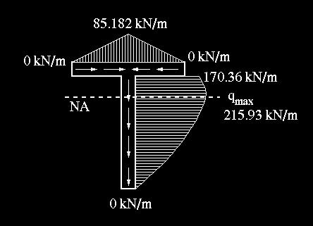
34 Torsion of Thin - Wall Closed Sections Derivation Consider a thin-walled member with a closed cross section subjected to pure torsion.

35 Examining the equilibrium of a small cutout of the skin reveals that
36
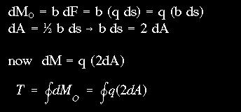
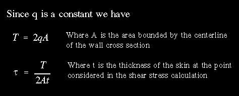
37 Angle of Twist By applying strain energy equation due to shear and Castigliano's Theorem the angle of twist for a thin-walled closed section can be shown to be Since T = 2qA, we have If the wall thickness is constant along each segment of the cross section, the integral can be replaced by a simple summation
38 Torsion - Shear Flow Relations in Multiple-Cell Thin- Wall Closed Sections The torsional moment in terms of the internal shear flow is simply

39 Derivation For equilibrium to be maintained at a exterior-interior wall (or web) junction point (point m in the figure) the shear flows entering should be equal to those leaving the junction Summing the moments about an arbitrary point O, and assuming clockwise direction to be positive, we obtain The moment equation above can be simplified to


40 Shear Stress Distribution and Angle of Twist for Two-Cell Thin-Walled Closed Sections The equation relating the shear flow along the exterior wall of each cell to the resultant torque at the section is given as This is a statically indeterminate problem. In order to find the shear flows q1 and q2, the compatibility relation between the angle of twist in cells 1 and 2 must be used. The compatibility requirement can be stated as where

41 The shear stress at a point of interest is found according to the equation To find the angle of twist, we could use either of the two twist formulas given above. It is also possible to express the angle of twist equation similar to that for a circular section
.")
 we use 2-0 and for cell (3) we use 3-0.")
42 Shear Stress Distribution and Angle of Twist for Multiple-Cell Thin- Wall Closed Sections In the figure above the area outside of the cross section will be designated as cell (0). Thus to designate the exterior walls of cell (1), we use the notation 1-0. Similarly for cell (2) we use 2-0 and for cell (3) we use 3-0. The interior walls will be designated by the names of adjacent cells. the torque of this multi-cell member can be related to the shear flows in exterior walls as follows


43 For elastic continuity, the angles of twist in all cells must be equal The direction of twist chosen to be positive is clockwise.


44 TRANSVERSE SHEAR LOADING OF BEAMS WITH CLOSED CROSS SECTIONS
 the location and magnitude of the maximum shear")
45 EXAMPLE For the thin-walled single-cell rectangular beam and loading shown, determine (a) the shear center location (ex and ey), (b) the resisting shear flow distribution at the root section due to the applied load of 1000 lb, (c) the location and magnitude of the maximum shear stress
46 Unit-III Structural Idealisation of Thin Walled Beams
47 Structural Idealization Consider the two-spar wing section shown. The stringers and spar carry most of the direct stresses while the skin carries the shear stresses. Since variation in stress over the stringer or spar flange due to bending of the wing would be small, it can be assumed to be constant.
48 Structural Idealization Stingers and spar flanges can then be replaced by concentrations of areas known as booms. It can be assumed that all direct stresses are carried by booms and the skin carries only shear. Direct stress carrying capacity of the skin may be accounted for by increasing the boom cross-section area.
49 Structural Idealization If skin does carry direct stress, we idealize it as a section that carries only shear stress, and add effective area to the booms. Right Side Similarly: Effective boom area due to skin carrying direct stress these add to the boom areas of flanges, strings, spars, etc..
50 Shear of open-section beams In the expression for shear flow in the cross-section: t D is the direct stress carrying thickness of the skin t D = t, if the skin is fully effective in carrying direct stress t D = 0, if the skin is assumed to carry only shear stress If we idealize skin as shown previously, then shear flow in the skin due to bending of the skin = 0. The above expression does not account for booms. How can we deal with booms that cause discontinuity in the skin and therefore interrupt the shear flow?
 and shear stresses in the skin")
51 Shear of open-section beams Sx and Sy produce direct stresses due to bending in the booms (and skin) and shear stresses in the skin
52 Shear of open-section beams r th boom has a cross-sectional area B r Shear flows in skin adjacent to it are q 1 and q 2. Equilibrium in z direction of previous figure This gives:
53 Recall: Shear of open-section beams
54 Shear of open-section beams This gives the change in shear flow induced by a boom. Each time a boom is encountered, the shear flow is incremented by this amount. If at some distance s at the profile, if n booms have been passed:
55 Open C/S Sample Problem Calculate the shear flow distribution in channel due to a 4.8 kn vertical shear load acting through the shear center. Booms carry all the direct stresses (B r = 300 mm 2 ) q s S I y xx n r 1 B r y r
56 Open C/S Sample Problem Calculate I xx : (Only consider direct stress carrying areas) I.e. Booms I xx Ad mm 2 q s n r 1 B r y r 10 4 n r 1 B r y r At the outside of boom 1, q s = 0. As boom 1 is crossed, the shear flow changes to: 4 q N/mm q 1
57 Open C/S Sample Problem There will be no further changes in shear flow until the next boom (2) is crossed. 4 q N/mm q q N/mm q 3 At the outside of boom 4, the shear flow is zero (q s = 0) as expected N/mm
58 Open C/S Sample Problem S 1 S 2 12 N/mm 6 N/mm q q q N/mm 12 N/mm 6 N/mm How come all the signs are negative? 6 N/mm S 3
59 Closed C/S Sample Problem For the single cell beam, the booms carry the direct stresses and the walls carry only the shear stress. A vertical shear load of 10 kn acts through the vertical plane between booms 3 and 6. Calculate the shear flow distribution
60 Closed C/S Sample Problem Centroid on Horizontal Axis of Symmetry. I xy = 0 Also S x = 0, t D = 0 q I xx s S I y xx n r 1 B r y r q s,0 I xx can be calculated from the direct stress carrying area of the booms 2 B 30 B 100 B 100 B Substituting B 1, B 4 gives I xx = x 10 6 mm 4 q s n r 1 B r y r q s, n r 1 B r y r q s,0
61 Closed C/S Sample Problem Introduce a cut in the wall 23 and calculate the basic shear flow around the walls q q q b,23 b,34 b,45 0 Since the t D = B 3 y N/mm B 4 y N/mm q q q q b,56 b,67 b,21 b,18 q q q b q b,34 b, N/mm (by symmetry) (by symmetry) , 87 b,21 B y N/mm B 1 y N/mm 18.1 N/mm (by symmetry)
62 Closed C/S Sample Problem Taking moments about the intersection of the line of action of shear load and horizontal axis: 0 pqbds 2Aqs,0 Solve for q s,0 is broken up into segments where each q b is constant Draw out the shear flow distribution to determine the sign of the moment generated by the shear flow on each segment
63 [ q b,81 2q q p s b,43 Closed C/S Sample Problem 2q b, q b,54 2q ] b, ,200q s,0 0 Substituting for the basic shear flow gives: q s, N/mm Enclosed Area, A Add q s,0 to the basic shear flow to get the total shear flow in every wall. In any wall the final shear flow is given by q s =q b + q s,0 so that q q q q q N/mm 5.4N/mm q 34.3 N/mm q 37.9 N/mm 17 N/mm q 87
64 UNIT- IV Structural and Loading Discontinuities in Thin Walled Beams
65 Closed section beams- shear stress distribution of a closed section beam built in at one end under bending, shear and torsion loads. If the moment centre is chosen to coincide with the lines of action of Sx and Sy then
66 Open section beams
67
68 Shear lag- effect of shearing strains in beamsredistribution of bending stresses due to restraining of warping, limitation of elementary bending theory, effect of accounting for shear lag on the estimated strength.
69 UNIT- V Stress Analysis of Aircraft Components- Wing, Fuselage:.
70 Wing spars and box beams- tapered wing spar, open and closed section beams, beams having variable stringer areas. Wings- Three-boom shell in bending, torsion, shear, tapered wings, deflections, cut-outs in wings. Bending, shear, torsion, cut-outs in fuselages. Fuselage frames and wing ribs- principles of stiffener/ web construction, fuselage frames, wing ribs
71
72
73
74
75
76
77
78
UNSYMMETRICAL BENDING
 UNSYMMETRICAL BENDING The general bending stress equation for elastic, homogeneous beams is given as (II.1) where Mx and My are the bending moments about the x and y centroidal axes, respectively. Ix and
INSTITUTE OF AERONAUTICAL ENGINEERING (Autonomous) Dundigal, Hyderabad
 Dundigal, Hyderabad") NSTTUTE OF AERONAUTCAL ENGNEERNG (Autonomous) Dundigal, Hyderabad - 00 043 AERONAUTCAL ENGNEERNG TUTORAL QUESTON BANK Course Name : ARCRAFT VEHCLES STRUCTURES Course Code : A2109 Class : B. Tech Semester
NSTTUTE OF AERONAUTCAL ENGNEERNG (Autonomous) Dundigal, Hyderabad - 00 043 AERONAUTCAL ENGNEERNG TUTORAL QUESTON BANK Course Name : ARCRAFT VEHCLES STRUCTURES Course Code : A2109 Class : B. Tech Semester
INSTITUTE OF AERONAUTICAL ENGINEERING (Autonomous) Dundigal, Hyderabad
 Dundigal, Hyderabad") INSTITUTE OF AERONAUTICAL ENGINEERING (Autonomous) Dundigal, Hyderabad - 500 043 AERONAUTICAL ENGINEERING TUTORIAL QUESTION BANK Course Name : ANALYSIS OF AIRCRAFT STRUCTURES Course Code : AAE006 Regulation
INSTITUTE OF AERONAUTICAL ENGINEERING (Autonomous) Dundigal, Hyderabad - 500 043 AERONAUTICAL ENGINEERING TUTORIAL QUESTION BANK Course Name : ANALYSIS OF AIRCRAFT STRUCTURES Course Code : AAE006 Regulation
2. (a) Explain different types of wing structures. (b) Explain the advantages and disadvantages of different materials used for aircraft
 Explain different types of wing structures. (b) Explain the advantages and disadvantages of different materials used for aircraft") Code No: 07A62102 R07 Set No. 2 III B.Tech II Semester Regular/Supplementary Examinations,May 2010 Aerospace Vehicle Structures -II Aeronautical Engineering Time: 3 hours Max Marks: 80 Answer any FIVE
Code No: 07A62102 R07 Set No. 2 III B.Tech II Semester Regular/Supplementary Examinations,May 2010 Aerospace Vehicle Structures -II Aeronautical Engineering Time: 3 hours Max Marks: 80 Answer any FIVE
Advanced Structural Analysis EGF Section Properties and Bending
 Advanced Structural Analysis EGF316 3. Section Properties and Bending 3.1 Loads in beams When we analyse beams, we need to consider various types of loads acting on them, for example, axial forces, shear
Lecture 15 Strain and stress in beams
 Spring, 2019 ME 323 Mechanics of Materials Lecture 15 Strain and stress in beams Reading assignment: 6.1 6.2 News: Instructor: Prof. Marcial Gonzalez Last modified: 1/6/19 9:42:38 PM Beam theory (@ ME
3. BEAMS: STRAIN, STRESS, DEFLECTIONS
 3. BEAMS: STRAIN, STRESS, DEFLECTIONS The beam, or flexural member, is frequently encountered in structures and machines, and its elementary stress analysis constitutes one of the more interesting facets
Aircraft Structures Beams Torsion & Section Idealization
 Universit of Liège Aerospace & Mechanical Engineering Aircraft Structures Beams Torsion & Section Idealiation Ludovic Noels omputational & Multiscale Mechanics of Materials M3 http://www.ltas-cm3.ulg.ac.be/
Unit 15 Shearing and Torsion (and Bending) of Shell Beams
 of Shell Beams") Unit 15 Shearing and Torsion (and Bending) of Shell Beams Readings: Rivello Ch. 9, section 8.7 (again), section 7.6 T & G 126, 127 Paul A. Lagace, Ph.D. Professor of Aeronautics & Astronautics and Engineering
Unit 15 Shearing and Torsion (and Bending) of Shell Beams Readings: Rivello Ch. 9, section 8.7 (again), section 7.6 T & G 126, 127 Paul A. Lagace, Ph.D. Professor of Aeronautics & Astronautics and Engineering
Mechanics of Solids notes
 Mechanics of Solids notes 1 UNIT II Pure Bending Loading restrictions: As we are aware of the fact internal reactions developed on any cross-section of a beam may consists of a resultant normal force,
Introduction to Aerospace Engineering
 Introduction to Aerospace Engineering Lecture slides Challenge the future 1 Aircraft & spacecraft loads Translating loads to stresses Faculty of Aerospace Engineering 29-11-2011 Delft University of Technology
Beam Bending Stresses and Shear Stress
 Beam Bending Stresses and Shear Stress Notation: A = name or area Aweb = area o the web o a wide lange section b = width o a rectangle = total width o material at a horizontal section c = largest distance
PURE BENDING. If a simply supported beam carries two point loads of 10 kn as shown in the following figure, pure bending occurs at segment BC.
 BENDING STRESS The effect of a bending moment applied to a cross-section of a beam is to induce a state of stress across that section. These stresses are known as bending stresses and they act normally
Chapter 3. Load and Stress Analysis
 Chapter 3 Load and Stress Analysis 2 Shear Force and Bending Moments in Beams Internal shear force V & bending moment M must ensure equilibrium Fig. 3 2 Sign Conventions for Bending and Shear Fig. 3 3
 UNIT III DEFLECTION OF BEAMS 1. What are the methods for finding out the slope and deflection at a section? The important methods used for finding out the slope and deflection at a section in a loaded
[8] Bending and Shear Loading of Beams
![[8] Bending and Shear Loading of Beams](/thumbs/92/110949676.jpg "[8] Bending and Shear Loading of Beams") [8] Bending and Shear Loading of Beams Page 1 of 28 [8] Bending and Shear Loading of Beams [8.1] Bending of Beams (will not be covered in class) [8.2] Bending Strain and Stress [8.3] Shear in Straight
[8] Bending and Shear Loading of Beams Page 1 of 28 [8] Bending and Shear Loading of Beams [8.1] Bending of Beams (will not be covered in class) [8.2] Bending Strain and Stress [8.3] Shear in Straight
Accordingly, the nominal section strength [resistance] for initiation of yielding is calculated by using Equation C-C3.1.
![Accordingly, the nominal section strength [resistance] for initiation of yielding is calculated by using Equation C-C3.1.](/thumbs/89/98617066.jpg "Accordingly, the nominal section strength [resistance] for initiation of yielding is calculated by using Equation C-C3.1.") C3 Flexural Members C3.1 Bending The nominal flexural strength [moment resistance], Mn, shall be the smallest of the values calculated for the limit states of yielding, lateral-torsional buckling and distortional
C3 Flexural Members C3.1 Bending The nominal flexural strength [moment resistance], Mn, shall be the smallest of the values calculated for the limit states of yielding, lateral-torsional buckling and distortional
Engineering Science OUTCOME 1 - TUTORIAL 4 COLUMNS
 Unit 2: Unit code: QCF Level: Credit value: 15 Engineering Science L/601/10 OUTCOME 1 - TUTORIAL COLUMNS 1. Be able to determine the behavioural characteristics of elements of static engineering systems
Chapter 3. Load and Stress Analysis. Lecture Slides
 Lecture Slides Chapter 3 Load and Stress Analysis 2015 by McGraw Hill Education. This is proprietary material solely for authorized instructor use. Not authorized for sale or distribution in any manner.
Stress Analysis Lecture 4 ME 276 Spring Dr./ Ahmed Mohamed Nagib Elmekawy
 Stress Analysis Lecture 4 ME 76 Spring 017-018 Dr./ Ahmed Mohamed Nagib Elmekawy Shear and Moment Diagrams Beam Sign Convention The positive directions are as follows: The internal shear force causes a
Unit III Theory of columns. Dr.P.Venkateswara Rao, Associate Professor, Dept. of Civil Engg., SVCE, Sriperumbudir
 Unit III Theory of columns 1 Unit III Theory of Columns References: Punmia B.C.,"Theory of Structures" (SMTS) Vol II, Laxmi Publishing Pvt Ltd, New Delhi 2004. Rattan.S.S., "Strength of Materials", Tata
Aircraft Structures Structural & Loading Discontinuities
 Universit of Liège Aerospace & Mechanical Engineering Aircraft Structures Structural & Loading Discontinuities Ludovic Noels Computational & Multiscale Mechanics of Materials CM3 http://www.ltas-cm3.ulg.ac.be/
CHAPTER 4: BENDING OF BEAMS
 (74) CHAPTER 4: BENDING OF BEAMS This chapter will be devoted to the analysis of prismatic members subjected to equal and opposite couples M and M' acting in the same longitudinal plane. Such members are
7.4 The Elementary Beam Theory
 7.4 The Elementary Beam Theory In this section, problems involving long and slender beams are addressed. s with pressure vessels, the geometry of the beam, and the specific type of loading which will be
Chapter 6: Cross-Sectional Properties of Structural Members
 Chapter 6: Cross-Sectional Properties of Structural Members Introduction Beam design requires the knowledge of the following. Material strengths (allowable stresses) Critical shear and moment values Cross
Downloaded from Downloaded from / 1
 PURWANCHAL UNIVERSITY III SEMESTER FINAL EXAMINATION-2002 LEVEL : B. E. (Civil) SUBJECT: BEG256CI, Strength of Material Full Marks: 80 TIME: 03:00 hrs Pass marks: 32 Candidates are required to give their
Design of Beams (Unit - 8)
") Design of Beams (Unit - 8) Contents Introduction Beam types Lateral stability of beams Factors affecting lateral stability Behaviour of simple and built - up beams in bending (Without vertical stiffeners)
Design of Beams (Unit - 8) Contents Introduction Beam types Lateral stability of beams Factors affecting lateral stability Behaviour of simple and built - up beams in bending (Without vertical stiffeners)
7 TRANSVERSE SHEAR transverse shear stress longitudinal shear stresses
 7 TRANSVERSE SHEAR Before we develop a relationship that describes the shear-stress distribution over the cross section of a beam, we will make some preliminary remarks regarding the way shear acts within
Properties of Sections
 ARCH 314 Structures I Test Primer Questions Dr.-Ing. Peter von Buelow Properties of Sections 1. Select all that apply to the characteristics of the Center of Gravity: A) 1. The point about which the body
CHAPTER 6: Shearing Stresses in Beams
 (130) CHAPTER 6: Shearing Stresses in Beams When a beam is in pure bending, the only stress resultants are the bending moments and the only stresses are the normal stresses acting on the cross sections.
PERIYAR CENTENARY POLYTECHNIC COLLEGE PERIYAR NAGAR - VALLAM THANJAVUR. DEPARTMENT OF MECHANICAL ENGINEERING QUESTION BANK
 PERIYAR CENTENARY POLYTECHNIC COLLEGE PERIYAR NAGAR - VALLAM - 613 403 - THANJAVUR. DEPARTMENT OF MECHANICAL ENGINEERING QUESTION BANK Sub : Strength of Materials Year / Sem: II / III Sub Code : MEB 310
FLEXIBILITY METHOD FOR INDETERMINATE FRAMES
 UNIT - I FLEXIBILITY METHOD FOR INDETERMINATE FRAMES 1. What is meant by indeterminate structures? Structures that do not satisfy the conditions of equilibrium are called indeterminate structure. These
Mechanics of Materials Primer
 Mechanics of Materials rimer Notation: A = area (net = with holes, bearing = in contact, etc...) b = total width of material at a horizontal section d = diameter of a hole D = symbol for diameter E = modulus
Symmetric Bending of Beams
 Symmetric Bending of Beams beam is any long structural member on which loads act perpendicular to the longitudinal axis. Learning objectives Understand the theory, its limitations and its applications
FIXED BEAMS IN BENDING
 FIXED BEAMS IN BENDING INTRODUCTION Fixed or built-in beams are commonly used in building construction because they possess high rigidity in comparison to simply supported beams. When a simply supported
Tuesday, February 11, Chapter 3. Load and Stress Analysis. Dr. Mohammad Suliman Abuhaiba, PE
 1 Chapter 3 Load and Stress Analysis 2 Chapter Outline Equilibrium & Free-Body Diagrams Shear Force and Bending Moments in Beams Singularity Functions Stress Cartesian Stress Components Mohr s Circle for
R13. II B. Tech I Semester Regular Examinations, Jan MECHANICS OF SOLIDS (Com. to ME, AME, AE, MTE) PART-A
 PART-A") SET - 1 II B. Tech I Semester Regular Examinations, Jan - 2015 MECHANICS OF SOLIDS (Com. to ME, AME, AE, MTE) Time: 3 hours Max. Marks: 70 Note: 1. Question Paper consists of two parts (Part-A and Part-B)
SET - 1 II B. Tech I Semester Regular Examinations, Jan - 2015 MECHANICS OF SOLIDS (Com. to ME, AME, AE, MTE) Time: 3 hours Max. Marks: 70 Note: 1. Question Paper consists of two parts (Part-A and Part-B)
Mechanics in Energy Resources Engineering - Chapter 5 Stresses in Beams (Basic topics)
") Week 7, 14 March Mechanics in Energy Resources Engineering - Chapter 5 Stresses in Beams (Basic topics) Ki-Bok Min, PhD Assistant Professor Energy Resources Engineering i Seoul National University Shear
Week 7, 14 March Mechanics in Energy Resources Engineering - Chapter 5 Stresses in Beams (Basic topics) Ki-Bok Min, PhD Assistant Professor Energy Resources Engineering i Seoul National University Shear
QUESTION BANK SEMESTER: III SUBJECT NAME: MECHANICS OF SOLIDS
 QUESTION BANK SEMESTER: III SUBJECT NAME: MECHANICS OF SOLIDS UNIT 1- STRESS AND STRAIN PART A (2 Marks) 1. Define longitudinal strain and lateral strain. 2. State Hooke s law. 3. Define modular ratio,
Design of Steel Structures Prof. S.R.Satish Kumar and Prof. A.R.Santha Kumar
 5.4 Beams As stated previousl, the effect of local buckling should invariabl be taken into account in thin walled members, using methods described alread. Laterall stable beams are beams, which do not
APPENDIX 1 MODEL CALCULATION OF VARIOUS CODES
 163 APPENDIX 1 MODEL CALCULATION OF VARIOUS CODES A1.1 DESIGN AS PER NORTH AMERICAN SPECIFICATION OF COLD FORMED STEEL (AISI S100: 2007) 1. Based on Initiation of Yielding: Effective yield moment, M n
QUESTION BANK DEPARTMENT: CIVIL SEMESTER: III SUBJECT CODE: CE2201 SUBJECT NAME: MECHANICS OF SOLIDS UNIT 1- STRESS AND STRAIN PART A
 DEPARTMENT: CIVIL SUBJECT CODE: CE2201 QUESTION BANK SEMESTER: III SUBJECT NAME: MECHANICS OF SOLIDS UNIT 1- STRESS AND STRAIN PART A (2 Marks) 1. Define longitudinal strain and lateral strain. 2. State
KINGS COLLEGE OF ENGINEERING DEPARTMENT OF MECHANICAL ENGINEERING QUESTION BANK. Subject code/name: ME2254/STRENGTH OF MATERIALS Year/Sem:II / IV
 KINGS COLLEGE OF ENGINEERING DEPARTMENT OF MECHANICAL ENGINEERING QUESTION BANK Subject code/name: ME2254/STRENGTH OF MATERIALS Year/Sem:II / IV UNIT I STRESS, STRAIN DEFORMATION OF SOLIDS PART A (2 MARKS)
Members Subjected to Combined Loads
 Members Subjected to Combined Loads Combined Bending & Twisting : In some applications the shaft are simultaneously subjected to bending moment M and Torque T.The Bending moment comes on the shaft due
2012 MECHANICS OF SOLIDS
 R10 SET - 1 II B.Tech II Semester, Regular Examinations, April 2012 MECHANICS OF SOLIDS (Com. to ME, AME, MM) Time: 3 hours Max. Marks: 75 Answer any FIVE Questions All Questions carry Equal Marks ~~~~~~~~~~~~~~~~~~~~~~
By Dr. Mohammed Ramidh
 Engineering Materials Design Lecture.6 the design of beams By Dr. Mohammed Ramidh 6.1 INTRODUCTION Finding the shear forces and bending moments is an essential step in the design of any beam. we usually
NATIONAL PROGRAM ON TECHNOLOGY ENHANCED LEARNING (NPTEL) IIT MADRAS Offshore structures under special environmental loads including fire-resistance
 IIT MADRAS Offshore structures under special environmental loads including fire-resistance") Week Eight: Advanced structural analyses Tutorial Eight Part A: Objective questions (5 marks) 1. theorem is used to derive deflection of curved beams with small initial curvature (Castigliano's theorem)
Week Eight: Advanced structural analyses Tutorial Eight Part A: Objective questions (5 marks) 1. theorem is used to derive deflection of curved beams with small initial curvature (Castigliano's theorem)
6. Bending CHAPTER OBJECTIVES
 CHAPTER OBJECTIVES Determine stress in members caused by bending Discuss how to establish shear and moment diagrams for a beam or shaft Determine largest shear and moment in a member, and specify where
OUTCOME 1 - TUTORIAL 3 BENDING MOMENTS. You should judge your progress by completing the self assessment exercises. CONTENTS
 Unit 2: Unit code: QCF Level: 4 Credit value: 15 Engineering Science L/601/1404 OUTCOME 1 - TUTORIAL 3 BENDING MOMENTS 1. Be able to determine the behavioural characteristics of elements of static engineering
Sub. Code:
 Important Instructions to examiners: ) The answers should be examined by key words and not as word-to-word as given in the model answer scheme. ) The model answer and the answer written by candidate may
1. Tasks of designing
 1 Lecture #18(14) Designing calculation of cross section of a highly aspect ratio wing Plan: 1 Tass of designing Distribution of shear force between wing spars Computation of the elastic center 4 Distribution
Shafts: Torsion of Circular Shafts Reading: Crandall, Dahl and Lardner 6.2, 6.3
 M9 Shafts: Torsion of Circular Shafts Reading: Crandall, Dahl and Lardner 6., 6.3 A shaft is a structural member which is long and slender and subject to a torque (moment) acting about its long axis. We
Members Subjected to Torsional Loads
 Members Subjected to Torsional Loads Torsion of circular shafts Definition of Torsion: Consider a shaft rigidly clamped at one end and twisted at the other end by a torque T = F.d applied in a plane perpendicular
CHAPTER -6- BENDING Part -1-
 Ishik University / Sulaimani Civil Engineering Department Mechanics of Materials CE 211 CHAPTER -6- BENDING Part -1-1 CHAPTER -6- Bending Outlines of this chapter: 6.1. Chapter Objectives 6.2. Shear and
Using the finite element method of structural analysis, determine displacements at nodes 1 and 2.
 Question 1 A pin-jointed plane frame, shown in Figure Q1, is fixed to rigid supports at nodes and 4 to prevent their nodal displacements. The frame is loaded at nodes 1 and by a horizontal and a vertical
Chapter 12 Elastic Stability of Columns
 Chapter 12 Elastic Stability of Columns Axial compressive loads can cause a sudden lateral deflection (Buckling) For columns made of elastic-perfectly plastic materials, P cr Depends primarily on E and
CH. 4 BEAMS & COLUMNS
 CH. 4 BEAMS & COLUMNS BEAMS Beams Basic theory of bending: internal resisting moment at any point in a beam must equal the bending moments produced by the external loads on the beam Rx = Cc + Tt - If the
UNIT 1 STRESS STRAIN AND DEFORMATION OF SOLIDS, STATES OF STRESS 1. Define stress. When an external force acts on a body, it undergoes deformation.
 UNIT 1 STRESS STRAIN AND DEFORMATION OF SOLIDS, STATES OF STRESS 1. Define stress. When an external force acts on a body, it undergoes deformation. At the same time the body resists deformation. The magnitude
COURSE TITLE : APPLIED MECHANICS & STRENGTH OF MATERIALS COURSE CODE : 4017 COURSE CATEGORY : A PERIODS/WEEK : 6 PERIODS/ SEMESTER : 108 CREDITS : 5
 COURSE TITLE : APPLIED MECHANICS & STRENGTH OF MATERIALS COURSE CODE : 4017 COURSE CATEGORY : A PERIODS/WEEK : 6 PERIODS/ SEMESTER : 108 CREDITS : 5 TIME SCHEDULE MODULE TOPICS PERIODS 1 Simple stresses
7.6 Stress in symmetrical elastic beam transmitting both shear force and bending moment
 7.6 Stress in symmetrical elastic beam transmitting both shear force and bending moment à It is more difficult to obtain an exact solution to this problem since the presence of the shear force means that
1. The structurally - power fuselage schemes.
 Lecture 24(14). Strength analysis of fuselages Plan: 1. The structurally - power fuselage schemes. 2. Strength calculation of the fuselages cross-sections. 3. The semimonocoque fuselage cross-section calculation.
Unit Workbook 1 Level 4 ENG U8 Mechanical Principles 2018 UniCourse Ltd. All Rights Reserved. Sample
 Pearson BTEC Levels 4 Higher Nationals in Engineering (RQF) Unit 8: Mechanical Principles Unit Workbook 1 in a series of 4 for this unit Learning Outcome 1 Static Mechanical Systems Page 1 of 23 1.1 Shafts
Mechanics of Materials II. Chapter III. A review of the fundamental formulation of stress, strain, and deflection
 Mechanics of Materials II Chapter III A review of the fundamental formulation of stress, strain, and deflection Outline Introduction Assumtions and limitations Axial loading Torsion of circular shafts
CHAPTER 5 PROPOSED WARPING CONSTANT
 122 CHAPTER 5 PROPOSED WARPING CONSTANT 5.1 INTRODUCTION Generally, lateral torsional buckling is a major design aspect of flexure members composed of thin-walled sections. When a thin walled section is
PDDC 1 st Semester Civil Engineering Department Assignments of Mechanics of Solids [ ] Introduction, Fundamentals of Statics
![PDDC 1 st Semester Civil Engineering Department Assignments of Mechanics of Solids [ ] Introduction, Fundamentals of Statics](/thumbs/92/109382806.jpg "PDDC 1 st Semester Civil Engineering Department Assignments of Mechanics of Solids [ ] Introduction, Fundamentals of Statics") Page1 PDDC 1 st Semester Civil Engineering Department Assignments of Mechanics of Solids [2910601] Introduction, Fundamentals of Statics 1. Differentiate between Scalar and Vector quantity. Write S.I.
Page1 PDDC 1 st Semester Civil Engineering Department Assignments of Mechanics of Solids [2910601] Introduction, Fundamentals of Statics 1. Differentiate between Scalar and Vector quantity. Write S.I.
ME325 EXAM I (Sample)
") ME35 EXAM I (Sample) NAME: NOTE: COSED BOOK, COSED NOTES. ONY A SINGE 8.5x" ORMUA SHEET IS AOWED. ADDITIONA INORMATION IS AVAIABE ON THE AST PAGE O THIS EXAM. DO YOUR WORK ON THE EXAM ONY (NO SCRATCH PAPER
ME35 EXAM I (Sample) NAME: NOTE: COSED BOOK, COSED NOTES. ONY A SINGE 8.5x" ORMUA SHEET IS AOWED. ADDITIONA INORMATION IS AVAIABE ON THE AST PAGE O THIS EXAM. DO YOUR WORK ON THE EXAM ONY (NO SCRATCH PAPER
Beams. Beams are structural members that offer resistance to bending due to applied load
 Beams Beams are structural members that offer resistance to bending due to applied load 1 Beams Long prismatic members Non-prismatic sections also possible Each cross-section dimension Length of member
DEPARTMENT OF CIVIL ENGINEERING
 KINGS COLLEGE OF ENGINEERING DEPARTMENT OF CIVIL ENGINEERING SUBJECT: CE 2252 STRENGTH OF MATERIALS UNIT: I ENERGY METHODS 1. Define: Strain Energy When an elastic body is under the action of external
Lecture Slides. Chapter 4. Deflection and Stiffness. The McGraw-Hill Companies 2012
 Lecture Slides Chapter 4 Deflection and Stiffness The McGraw-Hill Companies 2012 Chapter Outline Force vs Deflection Elasticity property of a material that enables it to regain its original configuration
STRESS STRAIN AND DEFORMATION OF SOLIDS, STATES OF STRESS
 1 UNIT I STRESS STRAIN AND DEFORMATION OF SOLIDS, STATES OF STRESS 1. Define: Stress When an external force acts on a body, it undergoes deformation. At the same time the body resists deformation. The
MODULE C: COMPRESSION MEMBERS
 MODULE C: COMPRESSION MEMBERS This module of CIE 428 covers the following subjects Column theory Column design per AISC Effective length Torsional and flexural-torsional buckling Built-up members READING:
If the number of unknown reaction components are equal to the number of equations, the structure is known as statically determinate.
 1 of 6 EQUILIBRIUM OF A RIGID BODY AND ANALYSIS OF ETRUCTURAS II 9.1 reactions in supports and joints of a two-dimensional structure and statically indeterminate reactions: Statically indeterminate structures
March 24, Chapter 4. Deflection and Stiffness. Dr. Mohammad Suliman Abuhaiba, PE
 Chapter 4 Deflection and Stiffness 1 2 Chapter Outline Spring Rates Tension, Compression, and Torsion Deflection Due to Bending Beam Deflection Methods Beam Deflections by Superposition Strain Energy Castigliano
Consider an elastic spring as shown in the Fig.2.4. When the spring is slowly
 .3 Strain Energy Consider an elastic spring as shown in the Fig..4. When the spring is slowly pulled, it deflects by a small amount u 1. When the load is removed from the spring, it goes back to the original
PES Institute of Technology
 PES Institute of Technology Bangalore south campus, Bangalore-5460100 Department of Mechanical Engineering Faculty name : Madhu M Date: 29/06/2012 SEM : 3 rd A SEC Subject : MECHANICS OF MATERIALS Subject
: APPLIED MECHANICS & STRENGTH OF MATERIALS COURSE CODE : 4021 COURSE CATEGORY : A PERIODS/ WEEK : 5 PERIODS/ SEMESTER : 75 CREDIT : 5 TIME SCHEDULE
 COURSE TITLE : APPLIED MECHANICS & STRENGTH OF MATERIALS COURSE CODE : 4021 COURSE CATEGORY : A PERIODS/ WEEK : 5 PERIODS/ SEMESTER : 75 CREDIT : 5 TIME SCHEDULE MODULE TOPIC PERIODS 1 Simple stresses
Design of Steel Structures Prof. S.R.Satish Kumar and Prof. A.R.Santha Kumar. Local buckling is an extremely important facet of cold formed steel
 5.3 Local buckling Local buckling is an extremely important facet of cold formed steel sections on account of the fact that the very thin elements used will invariably buckle before yielding. Thinner the
Flexural-Torsional Buckling of General Cold-Formed Steel Columns with Unequal Unbraced Lengths
 Proceedings of the Annual Stability Conference Structural Stability Research Council San Antonio, Texas, March 21-24, 2017 Flexural-Torsional Buckling of General Cold-Formed Steel Columns with Unequal
CE6306 STRENGTH OF MATERIALS TWO MARK QUESTIONS WITH ANSWERS ACADEMIC YEAR
 CE6306 STRENGTH OF MATERIALS TWO MARK QUESTIONS WITH ANSWERS ACADEMIC YEAR 2014-2015 UNIT - 1 STRESS, STRAIN AND DEFORMATION OF SOLIDS PART- A 1. Define tensile stress and tensile strain. The stress induced
5. What is the moment of inertia about the x - x axis of the rectangular beam shown?
 1 of 5 Continuing Education Course #274 What Every Engineer Should Know About Structures Part D - Bending Strength Of Materials NOTE: The following question was revised on 15 August 2018 1. The moment
For more Stuffs Visit Owner: N.Rajeev. R07
 Code.No: 43034 R07 SET-1 JAWAHARLAL NEHRU TECHNOLOGICAL UNIVERSITY HYDERABAD II.B.TECH - I SEMESTER REGULAR EXAMINATIONS NOVEMBER, 2009 FOUNDATION OF SOLID MECHANICS (AERONAUTICAL ENGINEERING) Time: 3hours
(48) CHAPTER 3: TORSION
 CHAPTER 3: TORSION") (48) CHAPTER 3: TORSION Introduction: In this chapter structural members and machine parts that are in torsion will be considered. More specifically, you will analyze the stresses and strains in members
(48) CHAPTER 3: TORSION Introduction: In this chapter structural members and machine parts that are in torsion will be considered. More specifically, you will analyze the stresses and strains in members
3 2 6 Solve the initial value problem u ( t) 3. a- If A has eigenvalues λ =, λ = 1 and corresponding eigenvectors 1
 3. a- If A has eigenvalues λ =, λ = 1 and corresponding eigenvectors 1") Math Problem a- If A has eigenvalues λ =, λ = 1 and corresponding eigenvectors 1 3 6 Solve the initial value problem u ( t) = Au( t) with u (0) =. 3 1 u 1 =, u 1 3 = b- True or false and why 1. if A is
Math Problem a- If A has eigenvalues λ =, λ = 1 and corresponding eigenvectors 1 3 6 Solve the initial value problem u ( t) = Au( t) with u (0) =. 3 1 u 1 =, u 1 3 = b- True or false and why 1. if A is
[7] Torsion. [7.1] Torsion. [7.2] Statically Indeterminate Torsion. [7] Torsion Page 1 of 21
![[7] Torsion. [7.1] Torsion. [7.2] Statically Indeterminate Torsion. [7] Torsion Page 1 of 21](/thumbs/88/115835122.jpg "[7] Torsion. [7.1] Torsion. [7.2] Statically Indeterminate Torsion. [7] Torsion Page 1 of 21") [7] Torsion Page 1 of 21 [7] Torsion [7.1] Torsion [7.2] Statically Indeterminate Torsion [7] Torsion Page 2 of 21 [7.1] Torsion SHEAR STRAIN DUE TO TORSION 1) A shaft with a circular cross section is
[7] Torsion Page 1 of 21 [7] Torsion [7.1] Torsion [7.2] Statically Indeterminate Torsion [7] Torsion Page 2 of 21 [7.1] Torsion SHEAR STRAIN DUE TO TORSION 1) A shaft with a circular cross section is
MECHANICS OF MATERIALS
 STATICS AND MECHANICS OF MATERIALS Ferdinand P. Beer E. Russell Johnston, Jr, John T. DeWolf David E Mazurek \Cawect Mc / iur/» Craw SugomcT Hilt Introduction 1 1.1 What is Mechanics? 2 1.2 Fundamental
Lecture-04 Design of RC Members for Shear and Torsion
 Lecture-04 Design of RC Members for Shear and Torsion By: Prof. Dr. Qaisar Ali Civil Engineering Department UET Peshawar drqaisarali@uetpeshawar.edu.pk www.drqaisarali.com 1 Topics Addressed Design of
BOOK OF COURSE WORKS ON STRENGTH OF MATERIALS FOR THE 2 ND YEAR STUDENTS OF THE UACEG
 BOOK OF COURSE WORKS ON STRENGTH OF MATERIALS FOR THE ND YEAR STUDENTS OF THE UACEG Assoc.Prof. Dr. Svetlana Lilkova-Markova, Chief. Assist. Prof. Dimitar Lolov Sofia, 011 STRENGTH OF MATERIALS GENERAL
Review Lecture. AE1108-II: Aerospace Mechanics of Materials. Dr. Calvin Rans Dr. Sofia Teixeira De Freitas
 Review Lecture AE1108-II: Aerospace Mechanics of Materials Dr. Calvin Rans Dr. Sofia Teixeira De Freitas Aerospace Structures & Materials Faculty of Aerospace Engineering Analysis of an Engineering System
Structural Analysis I Chapter 4 - Torsion TORSION
 ORSION orsional stress results from the action of torsional or twisting moments acting about the longitudinal axis of a shaft. he effect of the application of a torsional moment, combined with appropriate
twenty one concrete construction: shear & deflection ARCHITECTURAL STRUCTURES: FORM, BEHAVIOR, AND DESIGN DR. ANNE NICHOLS SUMMER 2014 lecture
 ARCHITECTURAL STRUCTURES: FORM, BEHAVIOR, AND DESIGN DR. ANNE NICHOLS SUMMER 2014 lecture twenty one concrete construction: Copyright Kirk Martini shear & deflection Concrete Shear 1 Shear in Concrete
Mechanics of Materials
 Mechanics of Materials 2. Introduction Dr. Rami Zakaria References: 1. Engineering Mechanics: Statics, R.C. Hibbeler, 12 th ed, Pearson 2. Mechanics of Materials: R.C. Hibbeler, 9 th ed, Pearson 3. Mechanics
Engineering Tripos Part IIA Supervisor Version. Module 3D4 Structural Analysis and Stability Handout 1
 Engineering Tripos Part A Supervisor Version Module 3D4 Structural Analysis and Stability Handout 1 Elastic Analysis (8 Lectures) Fehmi Cirak (fc86@) Stability (8 Lectures) Allan McRobie (fam @eng) January
Aircraft Structures Design Example
 University of Liège Aerospace & Mechanical Engineering Aircraft Structures Design Example Ludovic Noels Computational & Multiscale Mechanics of Materials CM3 http://www.ltas-cm3.ulg.ac.be/ Chemin des Chevreuils
4. BEAMS: CURVED, COMPOSITE, UNSYMMETRICAL
 4. BEMS: CURVED, COMPOSITE, UNSYMMETRICL Discussions of beams in bending are usually limited to beams with at least one longitudinal plane of symmetry with the load applied in the plane of symmetry or
ME Final Exam. PROBLEM NO. 4 Part A (2 points max.) M (x) y. z (neutral axis) beam cross-sec+on. 20 kip ft. 0.2 ft. 10 ft. 0.1 ft.
 M (x) y. z (neutral axis) beam cross-sec+on. 20 kip ft. 0.2 ft. 10 ft. 0.1 ft.") ME 323 - Final Exam Name December 15, 2015 Instructor (circle) PROEM NO. 4 Part A (2 points max.) Krousgrill 11:30AM-12:20PM Ghosh 2:30-3:20PM Gonzalez 12:30-1:20PM Zhao 4:30-5:20PM M (x) y 20 kip ft 0.2
ME 323 - Final Exam Name December 15, 2015 Instructor (circle) PROEM NO. 4 Part A (2 points max.) Krousgrill 11:30AM-12:20PM Ghosh 2:30-3:20PM Gonzalez 12:30-1:20PM Zhao 4:30-5:20PM M (x) y 20 kip ft 0.2
7.3 Design of members subjected to combined forces
 7.3 Design of members subjected to combined forces 7.3.1 General In the previous chapters of Draft IS: 800 LSM version, we have stipulated the codal provisions for determining the stress distribution in
Stresses in Curved Beam
 Stresses in Curved Beam Consider a curved beam subjected to bending moment M b as shown in the figure. The distribution of stress in curved flexural member is determined by using the following assumptions:
TORSION INCLUDING WARPING OF OPEN SECTIONS (I, C, Z, T AND L SHAPES)
") Page1 TORSION INCLUDING WARPING OF OPEN SECTIONS (I, C, Z, T AND L SHAPES) Restrained warping for the torsion of thin-wall open sections is not included in most commonly used frame analysis programs. Almost
Page1 TORSION INCLUDING WARPING OF OPEN SECTIONS (I, C, Z, T AND L SHAPES) Restrained warping for the torsion of thin-wall open sections is not included in most commonly used frame analysis programs. Almost
Stress Transformation Equations: u = +135 (Fig. a) s x = 80 MPa s y = 0 t xy = 45 MPa. we obtain, cos u + t xy sin 2u. s x = s x + s y.
 s x = 80 MPa s y = 0 t xy = 45 MPa. we obtain, cos u + t xy sin 2u. s x = s x + s y.") 014 Pearson Education, Inc., Upper Saddle River, NJ. All rights reserved. This material is protected under all copyright laws as they currently 9 7. Determine the normal stress and shear stress acting
014 Pearson Education, Inc., Upper Saddle River, NJ. All rights reserved. This material is protected under all copyright laws as they currently 9 7. Determine the normal stress and shear stress acting
3. Stability of built-up members in compression
 3. Stability of built-up members in compression 3.1 Definitions Build-up members, made out by coupling two or more simple profiles for obtaining stronger and stiffer section are very common in steel structures,