A THERMAL ACTUATOR DESIGN USING TORSIONAL LOADING TO ACHIEVE OUT-OF-PLANE MOTION AND FORCE TRANSMISSION
|
|
|
- Gabriella McKinney
- 6 years ago
- Views:
Transcription
1 A THERMAL ACTUATOR DESIGN USING TORSIONAL LOADING TO ACHIEVE OUT-OF-PLANE MOTION AND FORCE TRANSMISSION Anargyros Panayotopoulos MEMS Division, Mechanical Engineering Dept. University of California, Berkeley, CA USA ABSTRACT Thermal actuation is a regularity in MEMS devices, however much of the progress has been in demonstrating planar motion. This paper derives a mechanical way to achieve out-ofplane deflections using simple mechanical beams and basic thermal expansion techniques. Tip deflections were optimized over a range of voltages and varying actuator base geometry. By uniformly directing four -bars, possible deflections of 9 µm were calculated without shear failure for a maximum voltage of 15 volts. At constant voltage, deflections decreased to half of maximum for a base thickness of 10 µm. The force transmitted at the deflecting lever arms tip was calculated in the milli-newton range. 1. INTRODUCTION Thermal actuators have been used in a wide range of applications such as in microrelays, sensors, assembly systems, optical positioning and switching devices, and grippers [1-7]. The sensitive loading capacity, strength, and traveling range of microactuators has limited out-of-plane actuation growth [1]. Failure to observe key principles in MEMS, the understanding of material mechanics and electrical/thermal properties, has caused several MEMS devices to fail due to insufficient collaboration between mechanical and electrical engineers. Designs usually fall short of meeting both electrical and mechanical functional requirements, and thus, efficient out-of-plane actuators have not become readily available. MEMS devices can easily become out-of-plane actuators by taking advantage of basic principles of material mechanics. Much is already understood about stresses, bending, and torsion, and so planar actuators can easily actuate out-ofplane without external assistance, but by exploiting thermal expansion forces [2,3,5], to induce twisting motions. By concentrating stresses to pinpointed locations, an engineer can manipulate actuator arrays to deflect in any specified direction. The most prominent factors in limiting the feasibility and performance of these actuators are their geometrical design and physical properties [3,6,7]. Designs of previous thermal actuators achieved actuation by bending and buckling of structures [2,4,6,7,8]. Micron deflections can be achieved by utilizing variable beam cross sections, which concentrate current densities to induce resistance (Joule) heating [6,7]. Coupling multiple actuators in parallel to form arrays can more than double actuator displacement. Bimorph actuators observe slightly larger displacements in maximizing effects due to different thermal coefficients of exp ansion (TCE) [3,5,9,10]. Inplane and out-of-plane bimorph thermal actuators of single-crystal-silicon and aluminum have been demonstrated to rotate out-of-plane, under limited power input, but it was observed that continual increases in voltage decreased the total rotation angle [3]. Deflections have ranged from 0.5 to 16 µm out-of-plane depending highly on the geometric configuration of the actuator [5]. Residual stresses can also initially buckle actuators out-of-plane, however the precise controllability and exact positioning out-of-plane of the actuator poses a problem [10]. Torsional actuation out-of-plane has been developed using electrostatic comb drives resulting in micron deflections [1,4,8], though a maximum angle of twist of 20-degrees was observed before shear failure under a load of 25 volts [4]. The proposals goal was to develop test structures that achieved larger deflections, angles of twist, and transmitted forces than previous designs, particularly, to show that by guiding s using thermal expansion, out-of-plane actuators are not limited by geometry and strength requirements. 2. PROPOSED ACTUATOR DESIGN a) Design Process- To fabricate the polysilicon thermal actuator, a deep reactive ion etch (DRIE) bulk surface micromachining process will be
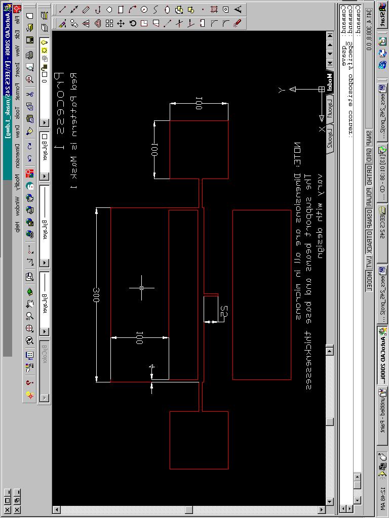
![used because high-aspect ratio needed for the various beams [9]. The simplicity of the multiple beam configuration is shown in Figure 1.](/docs-images/79/79985326/images/2-0.jpg "The design does not have complex geometries and only consists of rectangular beams. Figure 1. The prop osed thermal actuator model.")
2 used because high-aspect ratio needed for the various beams [9]. The simplicity of the multiple beam configuration is shown in Figure 1. The design does not have complex geometries and only consists of rectangular beams. Figure 1. The prop osed thermal actuator model. The four large squares represent anchors, the two grey beams are the support beams, the four red beams are the -bars, the blue element is the base, and the green bar is the deflecting lever arm. Limitations of the design include actuator compactness and allowable shear stress between support beams and the base. Depending on necessity and intentions, the actuator can take form in many different ways. Thus, the designer can alternate and change parameters to better suit his needs. This overall size limitation is up to the discretion of the working engineer. However, the more prominent concern resides in the connection feasibility between the base and support beams. The -bars can provide sufficient forces to rotate out-of-plane, but at the same time the shear force induced could tear the support beams from the base. Undesired overetching could also result in failure just as easily. In this case, theoretically possible designs could fail due to the shear force exerted at the reduced contact area between the base and the support beams. To prevent such failures, dimensional factors of safety should be added to designs at the expense of limiting the maximum achievable deflection pattern. b) Sample Calculations- Voltage applied to the -bars will stimulate resistance. Equating the electrical and thermal circuits, a temperature gradient is calculated.. 2 Q elec = V R, where R = ρl A. Q = ka * Τ / L cond Where V = 15 volts, the applied voltage ρ = 1250 µω-m, the resistivity of silicon [13] k= 150 W/m-K, the thermal conductivity of silicon [13] T = the temperature gradient L = 50 µm, the length of the toque-bar A = 16 µm 2, the cross sectional area of the -bar.. 2 Q elec = Q cond Τ = V ρ * k = 1200K Calculating the induced thermal of a single -bar, T = F exp L Where eff ε = γ Τ = 2.76*10 = σ A L = EεA 3 eff = the thermal strain for γ = 2.3 µk-1, TCE silicon E = 150 GPa, the Young s modulus of silicon L eff = 0.5 µm, the lever arm T = 3.3 nn-m The calculations use geometries representative of the -bars, while the polar moment of inertia calculated in the angle of twist equation below is that of the base and not the -bars. Using four bars, the total angle of twist, φ, in radians [13], TL φ = = 0. 37, [21 degrees] βjg Where T = 3.3 nn-m, the of a single -bar L = 150 µm, the half length of the base β = 0.141, the shape coefficient J = 6.25*10-22 m 4, the polar moment of inertia of the actuator base G = GPa, the shear modulus for the silicon A deflecting lever arm of 25 µm results in an out-of-plane deflection of 9 µm. The maximum shear stress between the support beams and base can be found by the following relationship [13], T τ = = 0.51GPa α( J / b) Where α = 0.208, the shear shape coefficient b = 5 µm, the base thickness It should be noted that throughout the simulation the base width and thickness were equal magnitude. The total transmitted force at the tip of the actuators deflecting lever arm, thus is Ftrans = ( T / Llever )cosφ = 490µ N L eff
3 3. TEST STRUCTURES Shown in Figure 1, the polysilicon actuators positions four -bars at the edges of the base, two being flush with the bottom surface and two flush to the top surface. Alternative connection designs of the -bars utilizing larger L eff values would provide larger s, resulting in a direct increase in the angle of twist, though for simplicity this model was considered. The support beams were designed to have a thickness equal to the base, however a width of only two-thirds to allow easier twisting, while still providing ample support. The provided by the actuator can be altered by two other methods as well: by simply adding more -bars to the design or by applying a preetch doping step to increase the actuators sensitivity to thermal gradients. To ensure a uniform doping profile, high temperature diffusion in situ (during deposition) would be used to add more charge carriers [11]. Careful consideration must be taken when doping and applying high voltages to the -bars to prevent plasticity and even liquidification. Increasing the length of the deflecting lever arm, while preserving the angle of twist, φ, would further increase deflections, however the transmitted perpendicular force would decrease. Multiple test structures were examined for varying base thicknesses and widths, over a range of voltage inputs to examine the overall effects and trends using MATLAB. Figure 3. Angles of twist for varying base thickness and input voltage. Figure 4. The transmitted perpendicular force for varying base thickness and input voltage. 5. PREDICTED RESULTS The following graphs describe the overall trends in out-of-plane deflection, angle of twist, the maximum shear stress incident to the support beam and base, and the total transmitted force. Figure 5. The total maximum shear stress for varying base thickness and input voltage. 6. DISCUSSION AND CONCLUSIONS Figure 2. Out-of-plane deflections for varying base thickness and input voltage. The plots of the out-of-plane deflection and angle of twist, shown in Figures 2 and 3, are represented as inverse logarithmic function of base thickness. These graphs indicate, for a constant voltage, deflections reduce to under half of its maximum when a thickness of 10 µm is reached. Therefore, to preserve total deflections, it is best to keep the width of the base small, yet
4 in doing so the total force transmitted is significantly minimized as seen in Figure 4. The actuators deflections also increases linearly with base length, and so longer beams could be beneficial, however, the possibility of buckling, failure by stiction, loss in overall strength and stiffness, and possible bowing could further reduce total transmitted force. For minimal base thickness, the total shear stress exposed to the support beams increases, shown in Figure 5, and then dramatically decreases similar to the deflection and angle of twist curves. This phenomenon results from the competing components, L eff and base thickness. The effective lever arm increases linearly and for small values this dominates over the base thickness that is proportional to the inverse third power. Once the maximum shear stress in the actuator was attained for 6 µm base thickness, the base thickness, then dominated L eff. This paper has reviewed a simple technique that achieves out-of-plane actuation with high transmittal force for applied voltages. Above all, in-plane thermal expansion laws can direct outof-plane displacements and forces. The limiting factors of the design happens to be the shear stress at the attachment points of the support beams and the geometrical dimensions of the base design. Previous designs indicated that shearing occurs at 8.5 GPa [1], which for these structures was preserved. 8. ACNOWLEDGEMENTS I would like to thank Professor Pister, UC Berkeley, for material presented in his EECS 245 lecture during the fall semester of 2001, and also the librarians of Bechtel Engineering Library for obtaining necessary sources. 9. REFERENCES [1] J. Hsieh, and W. Fang, A novel microelectrostatic torsional actuator, Sensors and Actuators Elsevier, Jan [2] T. Seki, et al., Thermal Buckling Actuator for microrelays, Solid-State Sensor and Actuator Workshop, Chicago, IL, [3] J. Noworolski, et al., Process for in-plane and out-of-plane single-crystal-silicon thermal microactuators, Sensors and Actuators Workshop on Thermal Investigations of ICs and Microstructures, Grenoble, France, Sept [4] M. Saif, and N. MacDonald, Micro mechanical single crystal silicon fracture studies Torsion and Bending, 9th Int. Workshop, IEEE, San Diego, CA Feb [5] S. Eagle, H. Lakdawala, and G. Fedder, Design and simulation of thermal actuators for STM applications in a standard CMOS process, Int. Society for Optical Engineering, Santa Clara, CA, USA, Sept [6] J. Comtois, and V. Bright, Surface micromachined polysilicon thermal actuator arrays and applications, Solid-State Sensor and Actuator Workshop, Hilton Head Island, SC, June [7] J. Comtois, and V. Bright, Applications for surface-micromachined polysilicon thermal actuators and arrays, Sensors and Actuators, Wright-Patterson AFB, OH, Jan [8] Idogaki, et al., Bending and expanding motion actuators, Sensors and Actuators Workshop, Nisshin-city, Japan, [9] J. Yeh, and N. Tien, Integrated polysilicon and DRIE bulk silicon micromachining for an electrostatic torsional actuator, Journal of MEMS, vol. 8, no. 4, Ithica, NY, Dec [10] X. Sun, X. Gu, and W. Carr, Lateral inplane displacement microactuators with combined thermal and electrostatic drive, Solid- State Sensor and Actuator Workshop, Hilton Head Island, SC, Jun [11] H. Kahn, et al., Mechanical properties of thick surface micromachined polysilicon films, 9th Int. Workshop, IEEE, San Diego, CA Feb [12] W. Callister, Material Science & Engineering, An Introduction, 4 th edition, John Wiley & Sons Inc., NY, [13] A. Ugural, and S Fenster, Advanced Strength and Applied Elasticity, 3 rd edition, Prentice Hall, Upper Saddle River, NJ, 1995.
5 FINAL LAYOUT
6 LAYOUT DESCRIPITIONS THE THERMAL ACTUATOR USING TORSIONAL LOADING TO ACHIEVE OUT-OF-PLANE MOTION AND FORCE TRANSMISSION To fabricate the polysilicon thermal actuator, a deep reactive ion etch (DRIE) bulk surface micromachining process will be used because high-aspect ratio needed for the various beams. The fabrication process will be similar to the one presented by Yeh and Jiang [9]. To build the multiple test structures, the SOI wafer will initially will have a µm thick silicon layer on top of a 1µm thick buried in oxide depending on the particular test structure to be fabricated. The majority of the etching will happen in the first etch step, under Process 1, as shown in mask descriptions on the following pages. Process 1 will etch entirely down to the oxide sacrificial layer. The general outline of the actuator is etched in this process and in Process 2 the two -bars attached to the lower end of the base are developed. This process will slowly etch the silicon layer so as to leave 4 µm layer above the oxide. This etch is critical to ensure the sufficient transmission of to the actuator. Process 3 will deposit the final layer of silicon to finalize the structure. However, due to the cavity where the two remaining -bars are to be positioned a sacrificial oxide deposition is necessary. Photoresist is used as the mask in all processes.
7
8
9
EE C247B / ME C218 INTRODUCTION TO MEMS DESIGN SPRING 2014 C. Nguyen PROBLEM SET #4
 Issued: Wednesday, Mar. 5, 2014 PROBLEM SET #4 Due (at 9 a.m.): Tuesday Mar. 18, 2014, in the EE C247B HW box near 125 Cory. 1. Suppose you would like to fabricate the suspended cross beam structure below
Foundations of MEMS. Chang Liu. McCormick School of Engineering and Applied Science Northwestern University. International Edition Contributions by
 Foundations of MEMS Second Edition Chang Liu McCormick School of Engineering and Applied Science Northwestern University International Edition Contributions by Vaishali B. Mungurwadi B. V. Bhoomaraddi
Design of Electrostatic Actuators for MOEMS Applications
 Design of Electrostatic Actuators for MOEMS Applications Dooyoung Hah 1,, Hiroshi Toshiyoshi 1,3, and Ming C. Wu 1 1 Department of Electrical Engineering, University of California, Los Angeles Box 951594,
EE C247B / ME C218 INTRODUCTION TO MEMS DESIGN SPRING 2016 C. NGUYEN PROBLEM SET #4
 Issued: Wednesday, March 4, 2016 PROBLEM SET #4 Due: Monday, March 14, 2016, 8:00 a.m. in the EE C247B homework box near 125 Cory. 1. This problem considers bending of a simple cantilever and several methods
December 1999 FINAL TECHNICAL REPORT 1 Mar Mar 98
 REPORT DOCUMENTATION PAGE AFRL-SR- BL_TR " Public reporting burden for this collection of information is estimated to average 1 hour per response, including the time for reviewing instruct the collection
Thermo-Mechanical Analysis of a Multi-Layer MEMS Membrane
 Thermo-Mechanical Analysis of a Multi-Layer MEMS Membrane Heiko Fettig, PhD James Wylde, PhD Nortel Networks - Optical Components Ottawa ON K2H 8E9 Canada Abstract This paper examines the modelling of
GENERAL CONTACT AND HYSTERESIS ANALYSIS OF MULTI-DIELECTRIC MEMS DEVICES UNDER THERMAL AND ELECTROSTATIC ACTUATION
 GENERAL CONTACT AND HYSTERESIS ANALYSIS OF MULTI-DIELECTRIC MEMS DEVICES UNDER THERMAL AND ELECTROSTATIC ACTUATION Yie He, James Marchetti, Carlos Gallegos IntelliSense Corporation 36 Jonspin Road Wilmington,
Y. C. Lee. Micro-Scale Engineering I Microelectromechanical Systems (MEMS)
") Micro-Scale Engineering I Microelectromechanical Systems (MEMS) Y. C. Lee Department of Mechanical Engineering University of Colorado Boulder, CO 80309-0427 leeyc@colorado.edu January 15, 2014 1 Contents
Micro-Scale Engineering I Microelectromechanical Systems (MEMS) Y. C. Lee Department of Mechanical Engineering University of Colorado Boulder, CO 80309-0427 leeyc@colorado.edu January 15, 2014 1 Contents
Bending Load & Calibration Module
 Bending Load & Calibration Module Objectives After completing this module, students shall be able to: 1) Conduct laboratory work to validate beam bending stress equations. 2) Develop an understanding of
b. The displacement of the mass due to a constant acceleration a is x=
 EE147/247A Final, Fall 2013 Page 1 /35 2 /55 NO CALCULATORS, CELL PHONES, or other electronics allowed. Show your work, and put final answers in the boxes provided. Use proper units in all answers. 1.
EECS C245 ME C218 Midterm Exam
 University of California at Berkeley College of Engineering EECS C245 ME C218 Midterm Eam Fall 2003 Prof. Roger T. Howe October 15, 2003 Dr. Thara Srinivasan Guidelines Your name: SOLUTIONS Circle your
Thermal Sensors and Actuators
 Thermal Sensors and Actuators Part I Fundamentals of heat transfer Heat transfer occurs where there is a temperature gradient until an equilibrium is reached. Four major mechanism Thermal conduction Natural
1. Narrative Overview Questions
 Homework 4 Due Nov. 16, 010 Required Reading: Text and Lecture Slides on Downloadable from Course WEB site: http://courses.washington.edu/overney/nme498.html 1. Narrative Overview Questions Question 1
Outline. 4 Mechanical Sensors Introduction General Mechanical properties Piezoresistivity Piezoresistive Sensors Capacitive sensors Applications
 Sensor devices Outline 4 Mechanical Sensors Introduction General Mechanical properties Piezoresistivity Piezoresistive Sensors Capacitive sensors Applications Introduction Two Major classes of mechanical
SUPPLEMENTARY INFORMATION
 In the format provided by the authors and unedited. DOI: 10.1038/NPHOTON.2016.254 Measurement of non-monotonic Casimir forces between silicon nanostructures Supplementary information L. Tang 1, M. Wang
SENSOR DEVICES MECHANICAL SENSORS
 SENSOR DEVICES MECHANICAL SENSORS OUTLINE 4 Mechanical Sensors Introduction General mechanical properties Piezoresistivity Piezoresistive sensors Capacitive sensors Applications INTRODUCTION MECHANICAL
EE C245 ME C218 Introduction to MEMS Design Fall 2007
 EE C245 ME C218 Introduction to MEMS Design Fall 2007 Prof. Clark T.-C. Nguyen Dept. of Electrical Engineering & Computer Sciences University of California at Berkeley Berkeley, CA 94720 Lecture 15: Beam
Platform Isolation Using Out-of-plane Compliant Mechanism
 Platform Isolation Using Out-of-plane Compliant Mechanism by Arpys Arevalo PhD Candidate in Electrical Engineering Computer, Electrical and Mathematical Sciences and Engineering (CEMSE) King Abdullah University
Abstract. 1 Introduction
 In R. A. Adey et al., eds., Simulation and Design of Microsystems and Microstructures (Proceedings of the 1st International Conference on Simulation and Design of Microsystems and Microstructures), Computational
EE C247B / ME C218 INTRODUCTION TO MEMS DESIGN SPRING 2014 PROBLEM SET #1
 Issued: Thursday, Jan. 30, 2014 PROBLEM SET #1 Due (at 9 a.m.): Wednesday Feb. 12, 2014, in the EE C247B HW box near 125 Cory. This homework assignment is intended to give you some early practice playing
Introduction to Microeletromechanical Systems (MEMS) Lecture 9 Topics. MEMS Overview
 Lecture 9 Topics. MEMS Overview") Introduction to Microeletromechanical Systems (MEMS) Lecture 9 Topics MicroOptoElectroMechanical Systems (MOEMS) Grating Light Valves Corner Cube Reflector (CCR) MEMS Light Modulator Optical Switch Micromirrors
Introduction to Microeletromechanical Systems (MEMS) Lecture 9 Topics MicroOptoElectroMechanical Systems (MOEMS) Grating Light Valves Corner Cube Reflector (CCR) MEMS Light Modulator Optical Switch Micromirrors
EE C245 ME C218 Introduction to MEMS Design Fall 2010
 EE C245 ME C218 Introduction to MEMS Design Fall 2010 Prof. Clark T.-C. Nguyen Dept. of Electrical Engineering & Computer Sciences University of California at Berkeley Berkeley, CA 94720 Lecture EE C245:
Finite Element Analysis of Piezoelectric Cantilever
 Finite Element Analysis of Piezoelectric Cantilever Nitin N More Department of Mechanical Engineering K.L.E S College of Engineering and Technology, Belgaum, Karnataka, India. Abstract- Energy (or power)
EE C245 ME C218 Introduction to MEMS Design Fall 2007
 EE C245 ME C218 Introduction to MEMS Design Fall 2007 Prof. Clark T.-C. Nguyen Dept. of Electrical Engineering & Computer Sciences University of California at Berkeley Berkeley, CA 94720 Lecture 12: Mechanics
EE C245 ME C218 Introduction to MEMS Design
 EE C245 ME C218 Introduction to MEMS Design Fall 2007 Prof. Clark T.-C. Nguyen Dept. of Electrical Engineering & Computer Sciences University of California at Berkeley Berkeley, CA 94720 ecture 15: Beam
EE C245 ME C218 Introduction to MEMS Design Fall 2007
 EE C245 ME C218 Introduction to MEMS Design Fall 2007 Prof. Clark T.-C. Nguyen Dept. of Electrical Engineering & Computer Sciences University of California at Berkeley Berkeley, CA 94720 Lecture 11: Bulk
EE C245 / ME C218 INTRODUCTION TO MEMS DESIGN FALL 2009 PROBLEM SET #7. Due (at 7 p.m.): Thursday, Dec. 10, 2009, in the EE C245 HW box in 240 Cory.
: Thursday, Dec. 10, 2009, in the EE C245 HW box in 240 Cory.") Issued: Thursday, Nov. 24, 2009 PROBLEM SET #7 Due (at 7 p.m.): Thursday, Dec. 10, 2009, in the EE C245 HW box in 240 Cory. 1. Gyroscopes are inertial sensors that measure rotation rate, which is an extremely
Issued: Thursday, Nov. 24, 2009 PROBLEM SET #7 Due (at 7 p.m.): Thursday, Dec. 10, 2009, in the EE C245 HW box in 240 Cory. 1. Gyroscopes are inertial sensors that measure rotation rate, which is an extremely
MODELING OF T-SHAPED MICROCANTILEVER RESONATORS. Margarita Narducci, Eduard Figueras, Isabel Gràcia, Luis Fonseca, Joaquin Santander, Carles Cané
 Stresa, Italy, 5-7 April 007 MODELING OF T-SHAPED MICROCANTILEVER RESONATORS Margarita Narducci, Eduard Figueras, Isabel Gràcia, Luis Fonseca, Joaquin Santander, Carles Centro Nacional de Microelectrónica
Institute for Electron Microscopy and Nanoanalysis Graz Centre for Electron Microscopy
 Institute for Electron Microscopy and Nanoanalysis Graz Centre for Electron Microscopy Micromechanics Ass.Prof. Priv.-Doz. DI Dr. Harald Plank a,b a Institute of Electron Microscopy and Nanoanalysis, Graz
MEMS tunable gratings with analog actuation
 Information Sciences 149 (2003) 31 40 www.elsevier.com/locate/ins MEMS tunable gratings with analog actuation Wei-Chuan Shih *, Chee Wei Wong, Yong Bae Jeon, Sang-Gook Kim, George Barbastathis Department
2.76/2.760 Multiscale Systems Design & Manufacturing
 2.76/2.760 Multiscale Systems Design & Manufacturing Fall 2004 MOEMS Devices for Optical communications system Switches and micromirror for Add/drops Diagrams removed for copyright reasons. MOEMS MEMS
CHAPTER 4 DESIGN AND ANALYSIS OF CANTILEVER BEAM ELECTROSTATIC ACTUATORS
 61 CHAPTER 4 DESIGN AND ANALYSIS OF CANTILEVER BEAM ELECTROSTATIC ACTUATORS 4.1 INTRODUCTION The analysis of cantilever beams of small dimensions taking into the effect of fringing fields is studied and
Piezoresistive Sensors
 Piezoresistive Sensors Outline Piezoresistivity of metal and semiconductor Gauge factor Piezoresistors Metal, silicon and polysilicon Close view of the piezoresistivity of single crystal silicon Considerations
CHAPTER 5 FIXED GUIDED BEAM ANALYSIS
 77 CHAPTER 5 FIXED GUIDED BEAM ANALYSIS 5.1 INTRODUCTION Fixed guided clamped and cantilever beams have been designed and analyzed using ANSYS and their performance were calculated. Maximum deflection
Design and Optimization of Piezoelectric Dual-Mode Micro-Mirror
 Design and Optimization of Piezoelectric Dual-Mode Micro-Mirror Jichao Zhong, Xingguo Xiong, Zheng Yao, Junling Hu*, Prabir Patra* Department of Electrical and Computer Engineering, *Department of Mechanical
Experiment Two (2) Torsional testing of Circular Shafts
 Torsional testing of Circular Shafts") Experiment Two (2) Torsional testing of Circular Shafts Introduction: Torsion occurs when any shaft is subjected to a torque. This is true whether the shaft is rotating (such as drive shafts on engines,
Experiment Two (2) Torsional testing of Circular Shafts Introduction: Torsion occurs when any shaft is subjected to a torque. This is true whether the shaft is rotating (such as drive shafts on engines,
Mechanical Design in Optical Engineering
 Torsion Torsion: Torsion refers to the twisting of a structural member that is loaded by couples (torque) that produce rotation about the member s longitudinal axis. In other words, the member is loaded
Design And Analysis of Microcantilevers With Various Shapes Using COMSOL Multiphysics Software
 Design And Analysis of Microcantilevers With Various Shapes Using COMSOL Multiphysics Software V. Mounika Reddy 1, G.V.Sunil Kumar 2 1,2 Department of Electronics and Instrumentation Engineering, Sree
Simulation of a Micro-Scale Out-of-plane Compliant Mechanism
 Simulation of a Micro-Scale Out-of-plane Compliant Mechanism by Arpys Arevalo PhD Candidate in Electrical Engineering Computer, Electrical and Mathematical Sciences and Engineering (CEMSE) King Abdullah
DESIGN AND SIMULATION OF UNDER WATER ACOUSTIC MEMS SENSOR
 DESIGN AND SIMULATION OF UNDER WATER ACOUSTIC MEMS SENSOR Smitha G Prabhu 1, Nagabhushana S *2 1 Dept. Of Electronics and communication, Center for Nano Materials and MEMS, 2 Dept. of Electronics and Communication,
SINGLE-STEP ASSEMBLY OF COMPLEX 3-D MICROSTRUCTURES
 SINGLE-STEP ASSEMBLY OF COMPLEX 3-D MICROSTRUCTURES Elliot E. Hui, Roger T. Howe, and M. Steven Rodgers* Berkeley Sensor & Actuator Center, University of California, Berkeley, CA 94720-1774, USA *Intelligent
CE 715: Advanced Strength of Materials
 CE 715: Advanced Strength of Materials Lecture 1 CE 715 Course Information Instructor: Tasnim Hassan Office: Mann Hall 419 Office Hours: TTh 2:00-4:00 pm Phone: 515-8123 Email: thassan@eos.ncsu.edu 1 Course
Strain Gages. Approximate Elastic Constants (from University Physics, Sears Zemansky, and Young, Reading, MA, Shear Modulus, (S) N/m 2
 N/m 2") When you bend a piece of metal, the Strain Gages Approximate Elastic Constants (from University Physics, Sears Zemansky, and Young, Reading, MA, 1979 Material Young's Modulus, (E) 10 11 N/m 2 Shear Modulus,
When you bend a piece of metal, the Strain Gages Approximate Elastic Constants (from University Physics, Sears Zemansky, and Young, Reading, MA, 1979 Material Young's Modulus, (E) 10 11 N/m 2 Shear Modulus,
Strain Measurement. Prof. Yu Qiao. Department of Structural Engineering, UCSD. Strain Measurement
 Strain Measurement Prof. Yu Qiao Department of Structural Engineering, UCSD Strain Measurement The design of load-carrying components for machines and structures requires information about the distribution
A Vertical Electrostatic Actuator with Extended Digital Range via Tailored Topology
 A Vertical Electrostatic Actuator with Extended Digital Range via Tailored Topology Yanhang Zhang and Martin L. Dunn Department of Mechanical Engineering University of Colorado at Boulder Boulder, CO 80309
EE C245 ME C218 Introduction to MEMS Design
 EE C245 ME C218 Introduction to MEMS Design Fall 2007 Prof. Clark T.-C. Nguyen Dept. of Electrical Engineering & Computer Sciences University of California at Berkeley Berkeley, CA 94720 Lecture 12: Mechanical
Practical 1P2 Young's Modulus and Stress Analysis
 Practical 1P Young's Modulus and Stress Analysis What you should learn from this practical Science This practical ties in with the lecture courses on elasticity. It will help you understand: 1. Hooke's
Materials: engineering, science, processing and design, 2nd edition Copyright (c)2010 Michael Ashby, Hugh Shercliff, David Cebon.
2010 Michael Ashby, Hugh Shercliff, David Cebon.") Modes of Loading (1) tension (a) (2) compression (b) (3) bending (c) (4) torsion (d) and combinations of them (e) Figure 4.2 1 Standard Solution to Elastic Problems Three common modes of loading: (a) tie
Modes of Loading (1) tension (a) (2) compression (b) (3) bending (c) (4) torsion (d) and combinations of them (e) Figure 4.2 1 Standard Solution to Elastic Problems Three common modes of loading: (a) tie
Curvature of a Cantilever Beam Subjected to an Equi-Biaxial Bending Moment. P. Krulevitch G. C. Johnson
 UCRL-JC-30440 PREPRINT Curvature of a Cantilever Beam Subjected to an Equi-Biaxial Bending Moment P. Krulevitch G. C. Johnson This paper was prepared for submittal to the Materials Research Society Spring
Wafer Charging in Process Equipment and its Relationship to GMR Heads Charging Damage
 Wafer Charging in Process Equipment and its Relationship to GMR Heads Charging Damage Wes Lukaszek Wafer Charging Monitors, Inc. 127 Marine Road, Woodside, CA 94062 tel.: (650) 851-9313, fax.: (650) 851-2252,
Design of a MEMS Capacitive Comb-drive Accelerometer
 Design of a MEMS Capacitive Comb-drive Accelerometer Tolga Kaya* 1, Behrouz Shiari 2, Kevin Petsch 1 and David Yates 2 1 Central Michigan University, 2 University of Michigan * kaya2t@cmich.edu Abstract:
Laboratory 7 Measurement on Strain & Force. Department of Mechanical and Aerospace Engineering University of California, San Diego MAE170
 Laboratory 7 Measurement on Strain & Force Department of Mechanical and Aerospace Engineering University of California, San Diego MAE170 Megan Ong Diana Wu Wong B01 Tuesday 11am May 17 th, 2015 Abstract:
ANALYSIS AND NUMERICAL MODELLING OF CERAMIC PIEZOELECTRIC BEAM BEHAVIOR UNDER THE EFFECT OF EXTERNAL SOLICITATIONS
 Third International Conference on Energy, Materials, Applied Energetics and Pollution. ICEMAEP016, October 30-31, 016, Constantine,Algeria. ANALYSIS AND NUMERICAL MODELLING OF CERAMIC PIEZOELECTRIC BEAM
Characterization of MEMS Devices
 MEMS: Characterization Characterization of MEMS Devices Prasanna S. Gandhi Assistant Professor, Department of Mechanical Engineering, Indian Institute of Technology, Bombay, Recap Characterization of MEMS
MAAE 2202 A. Come to the PASS workshop with your mock exam complete. During the workshop you can work with other students to review your work.
 It is most beneficial to you to write this mock final exam UNDER EXAM CONDITIONS. This means: Complete the exam in 3 hours. Work on your own. Keep your textbook closed. Attempt every question. After the
Review of Electromechanical Concepts
 Review of Electromechanical Concepts Part I Electrical properties p of semiconductors Free charge carriers in silicon Energy bands of insulators, semiconductors, and metals Charge carrier concentration
AC : MEMS FABRICATION AS A MULTIDISCIPLINARY LABORATORY
 AC 2007-524: MEMS FABRICATION AS A MULTIDISCIPLINARY LABORATORY Todd Kaiser, Montana State University Andrew Lingley, Montana State University Matt Leone, Montana State University Brad Pierson, Montana
MEMS Mechanical Fundamentals
 ROCHESTER INSTITUTE OF TECHNOLOGY MICROELECTRONIC ENGINEERING MEMS Mechanical Fundamentals Dr. Lynn Fuller webpage: http://people.rit.edu/lffeee Electrical and Microelectronic Engineering Rochester Institute
Design and Analysis of dual Axis MEMS Capacitive Accelerometer
 International Journal of Electronics Engineering Research. ISSN 0975-6450 Volume 9, Number 5 (2017) pp. 779-790 Research India Publications http://www.ripublication.com Design and Analysis of dual Axis
Natural vibration frequency of classic MEMS structures
 Natural vibration frequency of classic MEMS structures Zacarias E. Fabrim PGCIMAT, UFRGS, Porto Alegre, RS, Brazil Wang Chong, Manoel Martín Pérez Reimbold DeTec, UNIJUI, Ijuí, RS, Brazil Abstract This
Discontinuous Distributions in Mechanics of Materials
 Discontinuous Distributions in Mechanics of Materials J.E. Akin, Rice University 1. Introduction The study of the mechanics of materials continues to change slowly. The student needs to learn about software
STRAIN GAUGES YEDITEPE UNIVERSITY DEPARTMENT OF MECHANICAL ENGINEERING
 STRAIN GAUGES YEDITEPE UNIVERSITY DEPARTMENT OF MECHANICAL ENGINEERING 1 YEDITEPE UNIVERSITY ENGINEERING FACULTY MECHANICAL ENGINEERING LABORATORY 1. Objective: Strain Gauges Know how the change in resistance
Chapter 5 Torsion STRUCTURAL MECHANICS: CE203. Notes are based on Mechanics of Materials: by R. C. Hibbeler, 7th Edition, Pearson
 STRUCTURAL MECHANICS: CE203 Chapter 5 Torsion Notes are based on Mechanics of Materials: by R. C. Hibbeler, 7th Edition, Pearson Dr B. Achour & Dr Eng. K. El-kashif Civil Engineering Department, University
Micro Chemical Vapor Deposition System: Design and Verification
 Micro Chemical Vapor Deposition System: Design and Verification Q. Zhou and L. Lin Berkeley Sensor and Actuator Center, Department of Mechanical Engineering, University of California, Berkeley 2009 IEEE
MEMS Resonators That Are Robust to Process-Induced Feature Width Variations
 JOURNAL OF MICROELECTROMECHANICAL SYSTEMS, VOL. 11, NO. 5, OCTOBER 2002 505 MEMS Resonators That Are Robust to Process-Induced Feature Width Variations Rong Liu, Brad Paden, Senior Member, IEEE, and Kimberly
Optimizing the Performance of MEMS Electrostatic Comb Drive Actuator with Different Flexure Springs
 Optimizing the Performance of MEMS Electrostatic Comb Drive Actuator with Different Flexure Springs Shefali Gupta 1, Tanu Pahwa 1, Rakesh Narwal 1, B.Prasad 1, Dinesh Kumar 1 1 Electronic Science Department,
CIVL222 STRENGTH OF MATERIALS. Chapter 6. Torsion
 CIVL222 STRENGTH OF MATERIALS Chapter 6 Torsion Definition Torque is a moment that tends to twist a member about its longitudinal axis. Slender members subjected to a twisting load are said to be in torsion.
EE C245 ME C218 Introduction to MEMS Design
 EE C245 ME C218 Introduction to MEMS Design Fall 2007 Prof. Clark T.-C. Nguyen Dept. of Electrical Engineering & Computer Sciences University of California at Berkeley Berkeley, CA 94720 Lecture 16: Energy
SURFACE TENSION POWERED SELF-ASSEMBLY OF 3D MOEMS DEVICES USING DRIE OF BONDED SILICON-ON-INSULATOR WAFERS INTRODUCTION
 SURFACE TENSION POWERED SELF-ASSEMBLY OF 3D MOEMS DEVICES USING DRIE OF BONDED SILICON-ON-INSULATOR WAFERS R.R.A Syms, C. Gormley and S. Blackstone Dept. of Electrical and Electronic Engineering, Imperial
DESIGN AND FABRICATION OF THE MICRO- ACCELEROMETER USING PIEZOELECTRIC THIN FILMS
 DESIGN AND FABRICATION OF THE MICRO- ACCELEROMETER USING PIEZOELECTRIC THIN FILMS JYH-CHENG YU and FU-HSIN LAI Department of Mechanical Engineering National Taiwan University of Science and Technology
Strength of Materials Prof. S.K.Bhattacharya Dept. of Civil Engineering, I.I.T., Kharagpur Lecture No.26 Stresses in Beams-I
 Strength of Materials Prof. S.K.Bhattacharya Dept. of Civil Engineering, I.I.T., Kharagpur Lecture No.26 Stresses in Beams-I Welcome to the first lesson of the 6th module which is on Stresses in Beams
Tunable MEMS Capacitor for RF Applications
 Tunable MEMS Capacitor for RF Applications Shriram H S *1, Tushar Nimje 1, Dhruv Vakharia 1 1 BITS Pilani, Rajasthan, India *1167, 1 st Main, 2 nd Block, BEL Layout, Vidyaranyapura, Bangalore 560097; email:
Capacitive Sensor Interfaces
 Capacitive Sensor Interfaces Bernhard E. Boser Berkeley Sensor & Actuator Center Dept. of Electrical Engineering and Computer Sciences University of California, Berkeley Capacitive Sensor Interfaces 1996
Design and Analysis of Various Microcantilever Shapes for MEMS Based Sensing
 ScieTech 014 Journal of Physics: Conference Series 495 (014) 01045 doi:10.1088/174-6596/495/1/01045 Design and Analysis of Various Microcantilever Shapes for MEMS Based Sensing H. F. Hawari, Y. Wahab,
Analytical Design of Micro Electro Mechanical Systems (MEMS) based Piezoelectric Accelerometer for high g acceleration
 based Piezoelectric Accelerometer for high g acceleration") Analytical Design of Micro Electro Mechanical Systems (MEMS) based Piezoelectric Accelerometer for high g acceleration Arti Arora 1, Himanshu Monga 2, Anil Arora 3 Baddi University of Emerging Science
Analytical Design of Micro Electro Mechanical Systems (MEMS) based Piezoelectric Accelerometer for high g acceleration Arti Arora 1, Himanshu Monga 2, Anil Arora 3 Baddi University of Emerging Science
Integrating MEMS Electro-Static Driven Micro-Probe and Laser Doppler Vibrometer for Non-Contact Vibration Mode SPM System Design
 Tamkang Journal of Science and Engineering, Vol. 12, No. 4, pp. 399 407 (2009) 399 Integrating MEMS Electro-Static Driven Micro-Probe and Laser Doppler Vibrometer for Non-Contact Vibration Mode SPM System
MECHANICS OF MATERIALS
 2009 The McGraw-Hill Companies, Inc. All rights reserved. Fifth SI Edition CHAPTER 3 MECHANICS OF MATERIALS Ferdinand P. Beer E. Russell Johnston, Jr. John T. DeWolf David F. Mazurek Torsion Lecture Notes:
UNITS AND DEFINITIONS RELATED TO BIOMECHANICAL AND ELECTROMYOGRAPHICAL MEASUREMENTS
 APPENDIX B UNITS AND DEFINITIONS RELATED TO BIOMECHANICAL AND ELECTROMYOGRAPHICAL MEASUREMENTS All units used are SI (Système International d Unités). The system is based on seven well-defined base units
Modeling and simulation of multiport RF switch
 Journal of Physics: Conference Series Modeling and simulation of multiport RF switch To cite this article: J Vijay et al 006 J. Phys.: Conf. Ser. 4 715 View the article online for updates and enhancements.
Strain Gages. Approximate Elastic Constants (from University Physics, Sears Zemansky, and Young, Reading, MA, 1979
 Material Strain Gages Approximate Elastic Constants (from University Physics, Sears Zemansky, and Young, Reading, MA, 1979 Young's Modulus, Y Shear Modulus, S Bulk Modulus, B Poisson's Ratio 10 11 N/m
INTRODUCTION (Cont..)
") INTRODUCTION Name : Mohamad Redhwan Abd Aziz Post : Lecturer @ DEAN CENTER OF HND STUDIES Subject : Solid Mechanics Code : BME 2033 Room : CENTER OF HND STUDIES OFFICE H/P No. : 019-2579663 W/SITE : Http://tatiuc.edu.my/redhwan
INTRODUCTION Name : Mohamad Redhwan Abd Aziz Post : Lecturer @ DEAN CENTER OF HND STUDIES Subject : Solid Mechanics Code : BME 2033 Room : CENTER OF HND STUDIES OFFICE H/P No. : 019-2579663 W/SITE : Http://tatiuc.edu.my/redhwan
CE 221: MECHANICS OF SOLIDS I CHAPTER 1: STRESS. Dr. Krisada Chaiyasarn Department of Civil Engineering, Faculty of Engineering Thammasat university
 CE 221: MECHANICS OF SOLIDS I CHAPTER 1: STRESS By Dr. Krisada Chaiyasarn Department of Civil Engineering, Faculty of Engineering Thammasat university Agenda Introduction to your lecturer Introduction
Design and characterization of in-plane MEMS yaw rate sensor
 Sādhanā Vol. 34, Part 4, August 2009, pp. 633 642. Printed in India Design and characterization of in-plane MEMS yaw rate sensor K P VENKATESH, NISHAD PATIL, ASHOK KUMAR PANDEY and RUDRA PRATAP CranesSci
D : SOLID MECHANICS. Q. 1 Q. 9 carry one mark each. Q.1 Find the force (in kn) in the member BH of the truss shown.
 in the member BH of the truss shown.") D : SOLID MECHANICS Q. 1 Q. 9 carry one mark each. Q.1 Find the force (in kn) in the member BH of the truss shown. Q.2 Consider the forces of magnitude F acting on the sides of the regular hexagon having
D : SOLID MECHANICS Q. 1 Q. 9 carry one mark each. Q.1 Find the force (in kn) in the member BH of the truss shown. Q.2 Consider the forces of magnitude F acting on the sides of the regular hexagon having
BE Semester- I ( ) Question Bank (MECHANICS OF SOLIDS)
 Question Bank (MECHANICS OF SOLIDS)") BE Semester- I ( ) Question Bank (MECHANICS OF SOLIDS) All questions carry equal marks(10 marks) Q.1 (a) Write the SI units of following quantities and also mention whether it is scalar or vector: (i)
BE Semester- I ( ) Question Bank (MECHANICS OF SOLIDS) All questions carry equal marks(10 marks) Q.1 (a) Write the SI units of following quantities and also mention whether it is scalar or vector: (i)
Quiz #1 Practice Problem Set
 Name: Student Number: ELEC 3908 Physical Electronics Quiz #1 Practice Problem Set? Minutes January 22, 2016 - No aids except a non-programmable calculator - All questions must be answered - All questions
M 3 System for Viscous Drag Reduction
 122 Chapter 5 M 3 System for Viscous Drag Reduction In aerospace engineering, drag reduction is one of the most challenging problems of aircraft. Drag limits the maximum speed, the maximum range of flight
Today s Presentation
 Today s Presentation MEMS Comb Drive Actuator to Vary Tension & Compression of a Resonating Nano-Doubly Clamped Beam for High-Resolution & High Sensitivity Mass Detection Adam Hurst 1 John Regis 1 Chou
DESIGN AND SIMULATION OF ACCELEROMETER SPRINGS
 DESIGN AND SIMULATION OF ACCELEROMETER SPRINGS Marin Hristov Hristov 1, Kiril Toshkov Toshev 1, Krasimir Hristov Denishev 1, Vladimir Emilov Grozdanov 2, Dobromir Georgiev Gaydazhiev 2 1 Department of
Deformable MEMS grating for wide tunability and high operating speed
 Deformable MEMS grating for wide tunability and high operating speed Maurizio Tormen (1), Yves-Alain Peter (2), Philippe Niedermann (1), Arno Hoogerwerf (1), Herbert Shea (3) and Ross Stanley (1) 1 Centre
CMOS/BICMOS Self-assembling and Electrothermal Microactuators for Tunable Capacitors
 CMOS/BICMOS Self-assembling and Electrothermal Microactuators for Tunable Capacitors by Altug Oz A thesis submitted in partial fulfillment of the requirements for the degree of Master of Science in Electrical
Stress Analysis Lecture 3 ME 276 Spring Dr./ Ahmed Mohamed Nagib Elmekawy
 Stress Analysis Lecture 3 ME 276 Spring 2017-2018 Dr./ Ahmed Mohamed Nagib Elmekawy Axial Stress 2 Beam under the action of two tensile forces 3 Beam under the action of two tensile forces 4 Shear Stress
Mechanics of Materials II. Chapter III. A review of the fundamental formulation of stress, strain, and deflection
 Mechanics of Materials II Chapter III A review of the fundamental formulation of stress, strain, and deflection Outline Introduction Assumtions and limitations Axial loading Torsion of circular shafts
R13. II B. Tech I Semester Regular Examinations, Jan MECHANICS OF SOLIDS (Com. to ME, AME, AE, MTE) PART-A
 PART-A") SET - 1 II B. Tech I Semester Regular Examinations, Jan - 2015 MECHANICS OF SOLIDS (Com. to ME, AME, AE, MTE) Time: 3 hours Max. Marks: 70 Note: 1. Question Paper consists of two parts (Part-A and Part-B)
SET - 1 II B. Tech I Semester Regular Examinations, Jan - 2015 MECHANICS OF SOLIDS (Com. to ME, AME, AE, MTE) Time: 3 hours Max. Marks: 70 Note: 1. Question Paper consists of two parts (Part-A and Part-B)
Lecture 150 Basic IC Processes (10/10/01) Page ECE Analog Integrated Circuits and Systems P.E. Allen
 Page ECE Analog Integrated Circuits and Systems P.E. Allen") Lecture 150 Basic IC Processes (10/10/01) Page 1501 LECTURE 150 BASIC IC PROCESSES (READING: TextSec. 2.2) INTRODUCTION Objective The objective of this presentation is: 1.) Introduce the fabrication of
Lecture 150 Basic IC Processes (10/10/01) Page 1501 LECTURE 150 BASIC IC PROCESSES (READING: TextSec. 2.2) INTRODUCTION Objective The objective of this presentation is: 1.) Introduce the fabrication of
MCE603: Interfacing and Control of Mechatronic Systems
 MCE603: Interfacing and Control of Mechatronic Systems Chapter 7: Actuators and Sensors Topic 7d: Piezoelectric Actuators. Reference: Various articles. Cleveland State University Mechanical Engineering
Initial Stress Calculations
 Initial Stress Calculations The following are the initial hand stress calculations conducted during the early stages of the design process. Therefore, some of the material properties as well as dimensions
EE115C Winter 2017 Digital Electronic Circuits. Lecture 3: MOS RC Model, CMOS Manufacturing
 EE115C Winter 2017 Digital Electronic Circuits Lecture 3: MOS RC Model, CMOS Manufacturing Agenda MOS Transistor: RC Model (pp. 104-113) S R on D CMOS Manufacturing Process (pp. 36-46) S S C GS G G C GD
Learning Objectives By the end of this section, the student should be able to:
 Mechanics of Materials stress and strain flexural l beam bending analysis under simple loading conditions EECE 300 011 1 Learning Objectives By the end of this section, the student should be able to: describe
INTRODUCTION TO PIEZO TRANSDUCERS
 PIEZO SYSTEMS, INC. 65 Tower Office Park Woburn, MA 01801 USA Tel: 781 933 4850 Fax: 781 933 4743 email: sales@piezo.com Find Search for a product or category HOME PRODUCTS CUSTOM OEM CATALOG TECHNICAL