M R I Physics Course. Jerry Allison Ph.D., Chris Wright B.S., Tom Lavin B.S., Nathan Yanasak Ph.D. Department of Radiology Medical College of Georgia
|
|
|
- Evelyn McLaughlin
- 6 years ago
- Views:
Transcription
1 M R I Physics Course Jerry Allison Ph.D., Chris Wright B.S., Tom Lavin B.S., Nathan Yanasak Ph.D. Department of Radiology Medical College of Georgia
2 M R I Physics Course Spin Echo Imaging Hahn Spin Echo Spin - Warp Imaging Carr Purcell (CP) Pulse Sequence Carr Purcell Meiboom Gill (CPMG) Pulse Sequence Spin Echo Imaging Multiplanar Imaging Multislice Imaging Oblique imaging Spin Echo Variations
3 Spin Echo Imaging The Spin Echo imaging technique has the advantage that it is not as sensitive to inhomogeneity of the magnet and inhomogeneity caused by magnetic susceptibility of patient tissue. 3
4 Hahn Spin Echo The concept of Spin Echo production was developed by Hahn. Spin echoes are sometimes referred to as Hahn spin echoes. The Hahn Spin Echo technique consists of a 90 o flip (see Lecture 3), followed by an interpulse delay time, τ,, a 180 o flip, followed by a second interpulse delay (τ).( A spin echo occurs at echo time TE (2τ) following the initial 90 o flip as shown in the figure. 4
5 Hahn Spin Echo (continued) The Hahn Spin Echo was developed in 1950 for use 5 in nmr long before the advent of MRI.
6 Hahn Spin Echo (continued) The Hahn Spin Echo was used for the measurement of T 2 values. It is possible to measure T 2 since spin echo techniques compensate for local inhomogeneities of the static magnetic field. In order to measure T 2, the sequence had to be repeated with several different values of the interpulse delay (τ).( It was necessary to wait approximately 5 x T 1 (~4sec) for relaxation between sequences. 6
7 Hahn Spin Echo (continued) Due to the length of some interpulse delays, diffusion of nuclei (Brownian motion) contributed to relaxation and corrupted the measured T 2 values. Diffusion errors depend on gradient strength, diffusion coefficient (D) and diffusion time. In a spin echo technique, τ determines the diffusion time. 7
8 Spin-Warp Imaging Spin-warp imaging is a basic spin echo technique which reduces corruption of T 2 data due to magnet inhomogeneity and tissue susceptibility. In 2DFT techniques the variations in phase encoding associated with each TR can be accomplished by varying the magnitude of the gradient or the duration of the gradient. Spin-warp imaging varies the magnitude of phase encoding gradients (not the duration). Relaxation caused by flow, diffusion or proton exchange are not compensated by the spin echo technique, as mentioned before. 8
9 Here is a pulse- sequence diagram. This shows a timeline for: 1) RF pulses; 2) gradient amplitudes for Gx, Gy, Gz; 3) the readout (i.e., A/D), and 4) the signal of the excited nuclei. 9
10 Spin-Warp Imaging (continued) ****************** 10
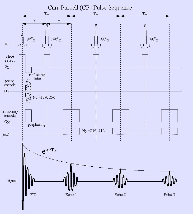
11 Carr-Purcell (CP) Pulse Sequence A modified spin echo technique is the Carr Purcell spin echo technique. The Carr-Purcell technique (CP pulse sequence) uses a 90 o RF pulse followed by a train of evenly spaced 180 o RF pulses. A series of echoes which have alternating signs are produced. The first echo is negative, the second echo is positive, the third echo is negative, etc. 11
12 Carr-Purcell (CP) Pulse Sequence An envelope connecting the echo amplitudes decays exponentially with a rate constant accurately reflecting the T 2 of the sample (as * opposed to T 2 ). Since τ is relatively short in the CP technique, diffusion errors in T 2 measurement are much smaller. One can use the exponential decay envelope to calculate T 2 values. 12
13 13
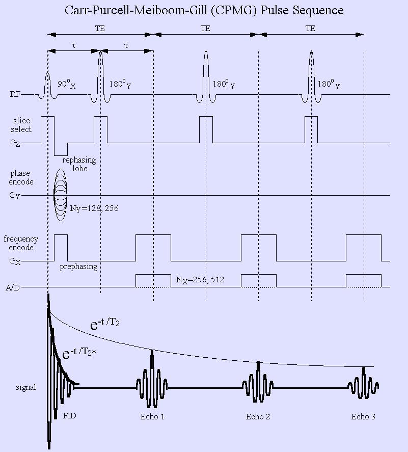
14 Carr-Purcell-Meiboom-Gill (CPMG) Pulse Sequence The Carr-Purcell-Meiboom-Gill ( CPMG sequence) The Carr-Purcell-Meiboom-Gill (CPMG technique is a modification of the Carr-Purcell technique. The CPMG technique applies the 180 o RF pulses along the Y axis of the rotating frame (rather than the X axis as in the CP technique). This modification makes the accuracy of the 180 o RF pulse much less critical. Each echo signal is positive in the CPMG technique. Variants of the CPMG technique have been widely used in MRI. 14
15 Carr-Purcell-Meiboom-Gill (CPMG) Pulse Sequence Another note of interest: the signal envelope following the 90 o RF pulse reflects T * 2, while the signal envelope connecting the magnitude of succeeding echoes reflects T 2. 15
16 16
17 Spin Echo Imaging First, let s go through the spin echo imaging sequence, see a demonstration of this, then finish up by discussing some timing issues of image acquisition: 17
18 1. Using a Z gradient for slice selection, the macroscopic magnetization is nutated into the transverse plane using a 90 o flip. Nutation is about the X axis. The Z gradient is reversed briefly to rephase the spins within the selected slice. 18
19 2. The Y phase encode gradient is applied with the first phase encode value. 19
20 3. After the interpulse delay time, τ, a slice selective 180 o RF pulse is applied to flip the transverse plane about the X axis (Spin-Warp, CP) or the Y axis (CPMG). The effect of the 180 o RF pulse is to retard the spins that were ahead in phase and to advance the spins that had retarded phase. 20

21 3. (continued): At time τ after the 180 o RF pulse (2τ after the 90 o RF pulse), the slow spins having advanced phase and the fast spins having retarded phase briefly reestablish phase coherence and a spin echo occurs. After phase coherence occurs the fast spins once again advance in phase and the slow spins fall behind in phase. 21
22 3. (continued): A second 180 o RF pulse at time 3τ 3 after the 90 o RF pulse can cause a second echo to occur at time 4τ 4 after the 90 o RF pulse. The second echo is smaller than the first echo, primarily due to T 2 relaxation. 22
 is enabled while the frequency encode gradient is active.")
23 4. During each echo period, the frequency encoding gradient is applied, during the collection of the signal induced in the RF coil. Notice that the Analog to Digital converter (A/D) is enabled while the frequency encode gradient is active. 23
24 Spin Echo Imaging (continued) 5. Pulse sequences are repeated. Consider a 256 x 256 acquisition matrix. 256 pulse sequences are executed with a different value of the phase encoding gradient to fill k-space (raw data). 24
25 Spin Echo Imaging (continued) It s movie time again before proceeding, let s see the spin-echo sequence in action to visualize how it works. 25
26 Spin Phase Plot Discussion We can overlay all excited spins onto one orbit, to show phase differences easily between all of them. The overlay is plotted on the right, from the perspective of the lab frame. Excited spins precessing in slice Overlay image, lab frame 26

27 Spin Phase Plot Discussion Phase differences between the spins are easier to see if we plot spin position while rotating the slice. Compare a plot on the left of the excited slice in rotation, to the simple overlay plot on the right. Excited spins in slice, showing rotation of the slice. Overlay image, rotating frame 27

28 Spin Phase Plot Discussion Because the total MRI signal is a sum of the signals from all spins, we see a maximum echo amplitude when all of the phases are nearly the same. Same phase, large echo Similar phases, noticeable echo Disparate phases, no echo 28
29 Spin Echo Movies Basic Carr-Purcell sequence (90 o x,, 180 o x) Spin in red leads in phase, and always progresses clockwise. Spin in blue lags in phase, and always progresses counter- clockwise. 29
30 Spin Echo Movies (continued) Basic Carr-Purcell-Meiboom-Gill sequence (90 o x,, 180 o ) y Spin in red leads in phase, and always progresses clockwise. Spin in blue lags in phase, and always progresses counter- clockwise. 30
.")
31 Spin Echo Movies (continued) Basic Carr-Purcell-Meiboom-Gill sequence (90 o x,, 180 o y), including T 2 decay. Spin in red leads in phase, and Spin in blue lags in phase, but notice the jitter in phase (T 2 ). Spin-echo sequence cannot correct for this, and echo is 31 smaller.
32 Spin Echo Imaging (continued) The time interval between each execution of the pulse sequence is termed the Repetition Time (TR). In the previous examples, each movie showed <1 TR worth of the sequence. 32
33 Spin Echo Imaging (continued) 6. The value of the repetition time (TR) and the echo time (TE) can be varied to control contrast in spin echo imaging. For example: TR = 2000 msec, TE = 20 msec Proton Density Weighting TR = 2000 msec TE = 80 msec T 2 Weighting TR = 600 msec TE = 20 msec T 1 Weighting Note that the echo time is typically short compared to the repetition time. We will return to this point in our discussion of multislice imaging. 33
34 Spin Echo Imaging (continued) 7. The image acquisition time can be calculated as follows: T S = N Y x TR x NEX where N Y = number of phase encodings (512, 256, 192, 128, n) TR = repetition time NEX = number of excitations (1, 2, n). Siemens terminology for NEX is Number of Acquisitions (No. Acq.). 34
35 Spin Echo Imaging (continued) 7. (continued): MRI images are sometimes acquired with a NEX greater than 1. For example, the number of excitations (NEX) might be set to 4 for a particular study. The result is that each line of k-space is sampled 4 times in order to improve signal-to-noise in the image. Image acquisition time is increased by 4. Signal in this case is improved by the square root of 4, (i.e., a factor of 2). In essence, each image is acquired 4 times and averaged together as 1 image. 35
36 Multiplanar Imaging Spin echo imaging techniques (as well as other MRI techniques) can be used to acquire axial, sagittal, coronal, or oblique images. The spin echo technique described above used the Z gradient for slice selection, the Y gradient for phase encoding and the X gradient for frequency encoding. This described the acquisition of an axial image. 36
37 Multiplanar Imaging (continued) Axial, sagittal, and coronal images can be acquired as follows: Notice that for each plane, the choice of axis for phase and frequency encoding can vary. 37
38 Multiplanar Imaging (continued) The MRI system usually chooses to apply the phase encoding axis along the thinner body dimension. For example, when acquiring an axial image of the thorax the phase encoding gradient is applied along the Y axis (anterior to posterior) since the AP dimension of the thorax is smaller than the left to right dimension. This selection helps to prevent wrap around in the phase encoding direction and may enable use of a rectangular field of view for faster scanning. The MRI system operator can choose to swap the direction of phase encoding and frequency encoding if necessary. 38
, creating aliasing.")
")
39 Multiplanar Imaging (continued) Aliasing example Phase- encode direction is A-P (longer axis of head), creating aliasing. Phase- encode direction is L-R (shorter axis of head), eliminating aliasing. Images from MRI Tutor website (Copyright( , All Rights Reserved) 39


40 Multiplanar Imaging (continued) The MRI system operator may also choose to swap the direction of phase encoding and frequency encoding to minimize flow artifacts in particular organs. Flow artifact Phase encode in the A-P direction. Phase encode in the 40 L-R direction.
41 Oblique Imaging Imaging of oblique planes can be accomplished by applying more than one gradient during the slice selective 90 o and 180 o RF pulses. If a Y gradient is applied during slice selection, an axial slice is defined. If Z and X gradients of equal magnitude are applied during slice selection, an axial oblique slice is defined. The axial oblique slice would be at an angle of 45 o to both the axial and sagittal planes. 41
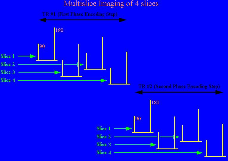
42 Multislice Imaging As shown earlier, echo time TE is typically short compared to the repetition time TR. The long TR is necessary to allow the excited slice to relax sufficiently between the first phase encoding sequence and subsequent phase encoding sequences. This time can be used efficiently by performing the first phase encoding on other slices while waiting to perform the second phase encoding sequence on the first slice. 42
43 Multislice Imaging (continued) For a T 1 weighted pulse sequence having a TR of 600 msec and TE of 20 msec, it is possible to perform the first phase encoding on approximately 12 slices before performing the second phase encoding on the first slice. For a 256 x 256 matrix, this means that data can be acquired from 12 different anatomic slices in the same time ( 2:41 minutes) required for a single slice. 43
44 44
45 Spin Echo Variations 1. MEMP (Multi Echo Multi Planar) techniques on a GE Signa allow the production of up to 4 evenly spaced (e.g. TE = 20, 40, 60, 80) echo images during image acquisition. 2. VEMP (Variable Echo Multi Planar) techniques on a GE Signa allow the production of 2 echo images during image acquisition. The echo times are variable and are not required to be evenly spaced (e.g. TE = 30,80) 45
46 Spin Echo Variations (continued) 3. Siemens supports single echo, dual echo and triple echo spin echo sequences. Echo times can be set by the operator (and need not be multiples). There is also a multiple echo technique that allows for production of up to 16 echoes for measurement of T 2 values. 46
47 Spin Echo Variations (continued) 4. k-space variations It is possible to reduce scan time by filling only part of the k-space or raw data matrix. The missing data is then synthesized using the symmetric properties of the matrix. If half of k-space is filled (NEX = 0.5) the scan takes less time to acquire but has a lower signal-to-noise ratio. We will discuss how this is possible in a later lecture. 47
Introduction to MRI. Spin & Magnetic Moments. Relaxation (T1, T2) Spin Echoes. 2DFT Imaging. K-space & Spatial Resolution.
 Spin Echoes. 2DFT Imaging. K-space & Spatial Resolution.") Introduction to MRI Spin & Magnetic Moments Relaxation (T1, T2) Spin Echoes 2DFT Imaging Selective excitation, phase & frequency encoding K-space & Spatial Resolution Contrast (T1, T2) Acknowledgement:
Introduction to MRI Spin & Magnetic Moments Relaxation (T1, T2) Spin Echoes 2DFT Imaging Selective excitation, phase & frequency encoding K-space & Spatial Resolution Contrast (T1, T2) Acknowledgement:
NMR and MRI : an introduction
 Intensive Programme 2011 Design, Synthesis and Validation of Imaging Probes NMR and MRI : an introduction Walter Dastrù Università di Torino walter.dastru@unito.it \ Introduction Magnetic Resonance Imaging
FREQUENCY SELECTIVE EXCITATION
 PULSE SEQUENCES FREQUENCY SELECTIVE EXCITATION RF Grad 0 Sir Peter Mansfield A 1D IMAGE Field Strength / Frequency Position FOURIER PROJECTIONS MR Image Raw Data FFT of Raw Data BACK PROJECTION Image Domain
Introduction to Biomedical Imaging
 Alejandro Frangi, PhD Computational Imaging Lab Department of Information & Communication Technology Pompeu Fabra University www.cilab.upf.edu MRI advantages Superior soft-tissue contrast Depends on among
The NMR Inverse Imaging Problem
 The NMR Inverse Imaging Problem Nuclear Magnetic Resonance Protons and Neutrons have intrinsic angular momentum Atoms with an odd number of proton and/or odd number of neutrons have a net magnetic moment=>
EL-GY 6813/BE-GY 6203 Medical Imaging, Fall 2016 Final Exam
 EL-GY 6813/BE-GY 6203 Medical Imaging, Fall 2016 Final Exam (closed book, 1 sheets of notes double sided allowed, no calculator or other electronic devices allowed) 1. Ultrasound Physics (15 pt) A) (9
Contrast Mechanisms in MRI. Michael Jay Schillaci
 Contrast Mechanisms in MRI Michael Jay Schillaci Overview Image Acquisition Basic Pulse Sequences Unwrapping K-Space Image Optimization Contrast Mechanisms Static and Motion Contrasts T1 & T2 Weighting,
Part III: Sequences and Contrast
 Part III: Sequences and Contrast Contents T1 and T2/T2* Relaxation Contrast of Imaging Sequences T1 weighting T2/T2* weighting Contrast Agents Saturation Inversion Recovery JUST WATER? (i.e., proton density
More NMR Relaxation. Longitudinal Relaxation. Transverse Relaxation
 More NMR Relaxation Longitudinal Relaxation Transverse Relaxation Copyright Peter F. Flynn 2017 Experimental Determination of T1 Gated Inversion Recovery Experiment The gated inversion recovery pulse sequence
Physics of MR Image Acquisition
 Physics of MR Image Acquisition HST-583, Fall 2002 Review: -MRI: Overview - MRI: Spatial Encoding MRI Contrast: Basic sequences - Gradient Echo - Spin Echo - Inversion Recovery : Functional Magnetic Resonance
Spin Echo Review. Static Dephasing: 1/T2 * = 1/T2 + 1/T2 Spin echo rephases magnetization Spin echoes can be repeated. B.Hargreaves - RAD 229
 Spin-Echo Sequences Spin Echo Review Echo Trains Applications: RARE, Single-shot, 3D Signal and SAR considerations Hyperechoes 1 Spin Echo Review Static Dephasing: 1/T2 * = 1/T2 + 1/T2 Spin echo rephases
Outlines: (June 11, 1996) Instructor:
 Instructor:") Magnetic Resonance Imaging (June 11, 1996) Instructor: Tai-huang Huang Institute of Biomedical Sciences Academia Sinica Tel. (02) 2652-3036; Fax. (02) 2788-7641 E. mail: bmthh@ibms.sinica.edu.tw Reference:
Magnetic Resonance Imaging (June 11, 1996) Instructor: Tai-huang Huang Institute of Biomedical Sciences Academia Sinica Tel. (02) 2652-3036; Fax. (02) 2788-7641 E. mail: bmthh@ibms.sinica.edu.tw Reference:
Pulse Sequences: RARE and Simulations
 Pulse Sequences: RARE and Simulations M229 Advanced Topics in MRI Holden H. Wu, Ph.D. 2018.04.19 Department of Radiological Sciences David Geffen School of Medicine at UCLA Class Business Final project
Principles of Nuclear Magnetic Resonance Microscopy
 Principles of Nuclear Magnetic Resonance Microscopy Paul T. Callaghan Department of Physics and Biophysics Massey University New Zealand CLARENDON PRESS OXFORD CONTENTS 1 PRINCIPLES OF IMAGING 1 1.1 Introduction
Nuclear Magnetic Resonance Imaging
 Nuclear Magnetic Resonance Imaging Jeffrey A. Fessler EECS Department The University of Michigan NSS-MIC: Fundamentals of Medical Imaging Oct. 20, 2003 NMR-0 Background Basic physics 4 magnetic fields
Exam 8N080 - Introduction to MRI
 Exam 8N080 - Introduction to MRI Friday April 10 2015, 18.00-21.00 h For this exam you may use an ordinary calculator (not a graphical one). In total there are 5 assignments and a total of 50 points can
EE225E/BIOE265 Spring 2016 Principles of MRI. Assignment 4. Due Friday Feb 19st, 2016, Self Grading Due Monday Feb 22nd, 2016
 EE225E/BIOE265 Spring 2016 Principles of MRI Miki Lustig Assignment 4 Due Friday Feb 19st, 2016, Self Grading Due Monday Feb 22nd, 2016 1. Finish reading Nishimura Ch.4 and Ch. 5. 2. The following pulse
NMR/MRI examination (8N080 / 3F240)
") NMR/MRI examination (8N080 / 3F240) Remarks: 1. This test consists of 3 problems with at total of 26 sub-questions. 2. Questions are in English. You are allowed to answer them in English or Dutch. 3. Please
NMR/MRI examination (8N080 / 3F240) Remarks: 1. This test consists of 3 problems with at total of 26 sub-questions. 2. Questions are in English. You are allowed to answer them in English or Dutch. 3. Please
Background II. Signal-to-Noise Ratio (SNR) Pulse Sequences Sampling and Trajectories Parallel Imaging. B.Hargreaves - RAD 229.
 Pulse Sequences Sampling and Trajectories Parallel Imaging. B.Hargreaves - RAD 229.") Background II Signal-to-Noise Ratio (SNR) Pulse Sequences Sampling and Trajectories Parallel Imaging 1 SNR: Signal-to-Noise Ratio Signal: Desired voltage in coil Noise: Thermal, electronic Noise Thermal
Background II Signal-to-Noise Ratio (SNR) Pulse Sequences Sampling and Trajectories Parallel Imaging 1 SNR: Signal-to-Noise Ratio Signal: Desired voltage in coil Noise: Thermal, electronic Noise Thermal
BMB 601 MRI. Ari Borthakur, PhD. Assistant Professor, Department of Radiology Associate Director, Center for Magnetic Resonance & Optical Imaging
 BMB 601 MRI Ari Borthakur, PhD Assistant Professor, Department of Radiology Associate Director, Center for Magnetic Resonance & Optical Imaging University of Pennsylvania School of Medicine A brief history
MRI in Review: Simple Steps to Cutting Edge Part I
 MRI in Review: Simple Steps to Cutting Edge Part I DWI is now 2 years old... Mike Moseley Radiology Stanford DWI, b = 1413 T2wt, 28/16 ASN 21 San Francisco + Disclosures: Funding NINDS, NCRR, NCI 45 minutes
MRI Physics I: Spins, Excitation, Relaxation
 MRI Physics I: Spins, Excitation, Relaxation Douglas C. Noll Biomedical Engineering University of Michigan Michigan Functional MRI Laboratory Outline Introduction to Nuclear Magnetic Resonance Imaging
Field trip: Tuesday, Feb 5th
 Pulse Sequences Field trip: Tuesday, Feb 5th Hardware tour of VUIIIS Philips 3T Meet here at regular class time (11.15) Complete MRI screening form! Chuck Nockowski Philips Service Engineer Reminder: Project/Presentation
Lab 1: Intro to NMR. March 10, 2014
 Lab 1: Intro to NMR March 10, 2014 Christine Leon-Swisher (GSI), Miki Lustig (Prof) 1 Preliminaries Never bring anything metal into the room with an MRI (i.e. keys, metallic jewelry, chairs) Do not enter
Lab 2: Magnetic Resonance Imaging
 EE225E/BIOE265 Spring 2013 Principles of MRI Miki Lustig Developed by: Galen Reed and Miki Lustig Lab 2: Magnetic Resonance Imaging Introduction In this lab, we will get some hands-on experience with an
Rochester Institute of Technology Rochester, New York. COLLEGE of Science Department of Chemistry. NEW (or REVISED) COURSE:
 COURSE:") Rochester Institute of Technology Rochester, New York COLLEGE of Science Department of Chemistry NEW (or REVISED) COURSE: 1014-730 1.0 Title: Magnetic Resonance Imaging (MRI) Date: July 2006 Credit Hours:
Rochester Institute of Technology Rochester, New York COLLEGE of Science Department of Chemistry NEW (or REVISED) COURSE: 1014-730 1.0 Title: Magnetic Resonance Imaging (MRI) Date: July 2006 Credit Hours:
Physical fundamentals of magnetic resonance imaging
 Physical fundamentals of magnetic resonance imaging Stepan Sereda University of Bonn 1 / 26 Why? Figure 1 : Full body MRI scan (Source: [4]) 2 / 26 Overview Spin angular momentum Rotating frame and interaction
MRI Physics II: Gradients, Imaging. Douglas C. Noll, Ph.D. Dept. of Biomedical Engineering University of Michigan, Ann Arbor
 MRI Physics II: Gradients, Imaging Douglas C., Ph.D. Dept. of Biomedical Engineering University of Michigan, Ann Arbor Magnetic Fields in MRI B 0 The main magnetic field. Always on (0.5-7 T) Magnetizes
BME I5000: Biomedical Imaging
 BME I5000: Biomedical Imaging Lecture 9 Magnetic Resonance Imaging (imaging) Lucas C. Parra, parra@ccny.cuny.edu Blackboard: http://cityonline.ccny.cuny.edu/ 1 Schedule 1. Introduction, Spatial Resolution,
Introduction to the Physics of NMR, MRI, BOLD fmri
 Pittsburgh, June 13-17, 2011 Introduction to the Physics of NMR, MRI, BOLD fmri (with an orientation toward the practical aspects of data acquisition) Pittsburgh, June 13-17, 2001 Functional MRI in Clinical
K-space. Spin-Warp Pulse Sequence. At each point in time, the received signal is the Fourier transform of the object s(t) = M( k x
 = M( k x") Bioengineering 280A Principles of Biomedical Imaging Fall Quarter 2015 MRI Lecture 4 k (t) = γ 2π k y (t) = γ 2π K-space At each point in time, the received signal is the Fourier transform of the object
Bioengineering 280A Principles of Biomedical Imaging Fall Quarter 2015 MRI Lecture 4 k (t) = γ 2π k y (t) = γ 2π K-space At each point in time, the received signal is the Fourier transform of the object
Magnetic Resonance Imaging. Pål Erik Goa Associate Professor in Medical Imaging Dept. of Physics
 Magnetic Resonance Imaging Pål Erik Goa Associate Professor in Medical Imaging Dept. of Physics pal.e.goa@ntnu.no 1 Why MRI? X-ray/CT: Great for bone structures and high spatial resolution Not so great
Nuclear Magnetic Resonance Imaging
 Nuclear Magnetic Resonance Imaging Simon Lacoste-Julien Electromagnetic Theory Project 198-562B Department of Physics McGill University April 21 2003 Abstract This paper gives an elementary introduction
Rad Tech 4912 MRI Registry Review. Outline of the Registry Exam: Certification Fees
 Rad Tech 4912 MRI Registry Review Outline of the Registry Exam: Category: # of questions: A. Patient Care 30 B. Imaging Procedures 62 C. Data Acquisition and Processing 65 D. Physical Principles of Image
Introduction to MRI Acquisition
 Introduction to MRI Acquisition James Meakin FMRIB Physics Group FSL Course, Bristol, September 2012 1 What are we trying to achieve? 2 What are we trying to achieve? Informed decision making: Protocols
RADIOLOGIV TECHNOLOGY 4912 COMPREHENSEIVE REVIEW/MRI WORSHEET #1- PATIENT CARE AND SAFETY/PHYSICAL PRINCIPLES
 RADIOLOGIV TECHNOLOGY 4912 COMPREHENSEIVE REVIEW/MRI WORSHEET #1- PATIENT CARE AND SAFETY/PHYSICAL PRINCIPLES 1. What are potential consequences to patients and personnel should there be a release of gaseous
Apodization. Gibbs Artifact. Bioengineering 280A Principles of Biomedical Imaging. Fall Quarter 2013 MRI Lecture 5. rect(k x )
") Bioengineering 280A Principles of Biomedical Imaging Fall Quarter 2013 MRI Lecture 5 GE Medical Systems 2003 Gibbs Artifact Apodization rect(k ) Hanning Window h(k )=1/2(1+cos(2πk ) 256256 image 256128
Bioengineering 280A Principles of Biomedical Imaging Fall Quarter 2013 MRI Lecture 5 GE Medical Systems 2003 Gibbs Artifact Apodization rect(k ) Hanning Window h(k )=1/2(1+cos(2πk ) 256256 image 256128
Principles of Magnetic Resonance Imaging
 Principles of Magnetic Resonance Imaging Hi Klaus Scheffler, PhD Radiological Physics University of 1 Biomedical Magnetic Resonance: 1 Introduction Magnetic Resonance Imaging Contents: Hi 1 Introduction
BASIC MRI PHYSICS SPIN GYMNASTICS Don Plewes PhD, Walter Kucharczyk MD
 BASIC MRI PHYSICS SPIN GYMNASTICS Don Plewes PhD, Walter Kucharczyk MD Introduction To understand MRI, it is first necessary to understand the physics of proton Nuclear Magnetic Resonance (NMR). The most
Diffusion Tensor Imaging (DTI): An overview of key concepts
: An overview of key concepts") Diffusion Tensor Imaging (DTI): An overview of key concepts (Supplemental material for presentation) Prepared by: Nadia Barakat BMB 601 Chris Conklin Thursday, April 8 th 2010 Diffusion Concept [1,2]:
Diffusion Tensor Imaging (DTI): An overview of key concepts (Supplemental material for presentation) Prepared by: Nadia Barakat BMB 601 Chris Conklin Thursday, April 8 th 2010 Diffusion Concept [1,2]:
Basic MRI physics and Functional MRI
 Basic MRI physics and Functional MRI Gregory R. Lee, Ph.D Assistant Professor, Department of Radiology June 24, 2013 Pediatric Neuroimaging Research Consortium Objectives Neuroimaging Overview MR Physics
MRI in Practice. Catherine Westbrook MSc, DCRR, CTC Senior Lecturer Anglia Polytechnic University Cambridge UK. John Talbot MSc, DCRR
 MRI in Practice Third edition Catherine Westbrook MSc, DCRR, CTC Senior Lecturer Anglia Polytechnic University Cambridge UK and Carolyn Kaut RothRT(R) (MR) (CT) (M) (CV) Fellow SMRT (Section for Magnetic
Navigator Echoes. BioE 594 Advanced Topics in MRI Mauli. M. Modi. BioE /18/ What are Navigator Echoes?
 Navigator Echoes BioE 594 Advanced Topics in MRI Mauli. M. Modi. 1 What are Navigator Echoes? In order to correct the motional artifacts in Diffusion weighted MR images, a modified pulse sequence is proposed
2.1.1 A Brief History of NMR The conception of NMR sprouted after the Pauli s prediction of nuclear spin in
 CHAPTER--2 BASICS OF NMR IMAGING AND SPECTROSCOPY 2.1 Introduction 2.1.1 A Brief History of NMR The conception of NMR sprouted after the Pauli s prediction of nuclear spin in 1924. Later Gorter (1936)
BNG/ECE 487 FINAL (W16)
") BNG/ECE 487 FINAL (W16) NAME: 4 Problems for 100 pts This exam is closed-everything (no notes, books, etc.). Calculators are permitted. Possibly useful formulas and tables are provided on this page. Fourier
BNG/ECE 487 FINAL (W16) NAME: 4 Problems for 100 pts This exam is closed-everything (no notes, books, etc.). Calculators are permitted. Possibly useful formulas and tables are provided on this page. Fourier
Suppression of Static Magnetic Field in Diffusion Measurements of Heterogeneous Materials
 PIERS ONLINE, VOL. 5, NO. 1, 2009 81 Suppression of Static Magnetic Field in Diffusion Measurements of Heterogeneous Materials Eva Gescheidtova 1 and Karel Bartusek 2 1 Faculty of Electrical Engineering
Introduction to Magnetic Resonance Imaging
 Introduction to Magnetic Resonance Imaging MRI of the brain, ca. 1978. ca. 1993 ca. 2006 2014 Modality Characteristics and Comparison Radiography CT scanning Nuclear medicine MRI transmission modalities
ROCHESTER INSTITUTE OF TECHNOLOGY COURSE OUTLINE FORM COLLEGE OF SCIENCE. Chester F. Carlson Center for Imaging Science
 ROCHESTER INSTITUTE OF TECHNOLOGY COURSE OUTLINE FORM COLLEGE OF SCIENCE Chester F. Carlson Center for Imaging Science NEW COURSE: COS-IMGS-730 Magnetic Resonance Imaging 1.0 Course Designations and Approvals
G Medical Imaging. Outline 4/13/2012. Physics of Magnetic Resonance Imaging
 G16.4426 Medical Imaging Physics of Magnetic Resonance Imaging Riccardo Lattanzi, Ph.D. Assistant Professor Department of Radiology, NYU School of Medicine Department of Electrical and Computer Engineering,
Spatial encoding in Magnetic Resonance Imaging. Jean-Marie BONNY
 Spatial encoding in Magnetic Resonance Imaging Jean-Marie BONNY What s Qu est an image ce qu une? image? «a reproduction of a material object by a camera or a related technique» Multi-dimensional signal
CONTENTS. 2 CLASSICAL DESCRIPTION 2.1 The resonance phenomenon 2.2 The vector picture for pulse EPR experiments 2.3 Relaxation and the Bloch equations
 CONTENTS Preface Acknowledgements Symbols Abbreviations 1 INTRODUCTION 1.1 Scope of pulse EPR 1.2 A short history of pulse EPR 1.3 Examples of Applications 2 CLASSICAL DESCRIPTION 2.1 The resonance phenomenon
Spatial encoding in Magnetic Resonance Imaging. Jean-Marie BONNY
 Spatial encoding in Magnetic Resonance Imaging Jean-Marie BONNY What s Qu est an image ce qu une? image? «a reproduction of a material object by a camera or a related technique» Multi-dimensional signal
EE225E/BIOE265 Spring 2013 Principles of MRI. Assignment 9 Solutions. Due April 29th, 2013
 EE5E/BIOE65 Spring 013 Principles of MRI Miki Lustig This is the last homework in class. Enjoy it. Assignment 9 Solutions Due April 9th, 013 1) In class when we presented the spin-echo saturation recovery
CHEM / BCMB 4190/6190/8189. Introductory NMR. Lecture 10
 CHEM / BCMB 490/690/889 Introductory NMR Lecture 0 - - CHEM 490/690 Spin-Echo The spin-echo pulse sequence: 90 - τ - 80 - τ(echo) Spins echoes are widely used as part of larger pulse sequence to refocus
Mehrphasen Durchflussmessung mit Hilfe von Kernspinresonanzspektroskopie
 Fachtagung Lasermethoden in der Strömungsmesstechnik 8. 10. September 2015, Dresden Mehrphasen Durchflussmessung mit Hilfe von Kernspinresonanzspektroskopie Multiphase flow metering with nuclear magnetic
Advanced Topics and Diffusion MRI
 Advanced Topics and Diffusion MRI Slides originally by Karla Miller, FMRIB Centre Modified by Mark Chiew (mark.chiew@ndcn.ox.ac.uk) Slides available at: http://users.fmrib.ox.ac.uk/~mchiew/teaching/ MRI
MR Advance Techniques. Flow Phenomena. Class I
 MR Advance Techniques Flow Phenomena Class I Flow Phenomena In this class we will explore different phenomenona produced from nuclei that move during the acquisition of data. Flowing nuclei exhibit different
Principles of Magnetic Resonance
 С. Р. Slichter Principles of Magnetic Resonance Third Enlarged and Updated Edition With 185 Figures Springer-Verlag Berlin Heidelberg New York London Paris Tokyo Hong Kong Contents 1. Elements of Resonance
Introductory MRI Physics
 C HAPR 18 Introductory MRI Physics Aaron Sodickson EXRNAL MAGNETIC FIELD, PROTONS AND EQUILIBRIUM MAGNETIZATION Much of the bulk of the magnetic resonance imaging (MRI) scanner apparatus is dedicated to
} B 1 } Coil } Gradients } FFT
 Introduction to MRI Daniel B. Ennis, Ph.D. Requirements for MRI UCLA DCVI Requirements for MRI Dipoles to Images MR Active uclei e.g. 1 H in H20 Cryogen Liquid He and 2 Magnetic Field (B0) Polarizer ystem
Magnetic Resonance Imaging in Medicine
 Institute for Biomedical Engineering University and ETH Zurich Gloriastrasse 35 CH- 8092 Zurich Switzerland Magnetic Resonance Imaging in Medicine D. Meier, P. Boesiger, S. Kozerke 2012 All rights reserved.
Sketch of the MRI Device
 Outline for Today 1. 2. 3. Introduction to MRI Quantum NMR and MRI in 0D Magnetization, m(x,t), in a Voxel Proton T1 Spin Relaxation in a Voxel Proton Density MRI in 1D MRI Case Study, and Caveat Sketch
M R I Physics Course
 M R I Physics Course Some Body Techniques/Protocols Nathan Yanasak, Ph.D. Jerry Allison, Ph.D. Tom Lavin, M.S. Department of Radiology Medical College of Georgia References: 1) The Physics of Clinical
Tissue Parametric Mapping:
 Tissue Parametric Mapping: Contrast Mechanisms Using SSFP Sequences Jongho Lee Department of Radiology University of Pennsylvania Tissue Parametric Mapping: Contrast Mechanisms Using bssfp Sequences Jongho
Magnetization Gradients, k-space and Molecular Diffusion. Magnetic field gradients, magnetization gratings and k-space
 2256 Magnetization Gradients k-space and Molecular Diffusion Magnetic field gradients magnetization gratings and k-space In order to record an image of a sample (or obtain other spatial information) there
Fundamental MRI Principles Module Two
 Fundamental MRI Principles Module Two 1 Nuclear Magnetic Resonance There are three main subatomic particles: protons neutrons electrons positively charged no significant charge negatively charged Protons
Basic p rinciples COPYRIGHTED MATERIAL. Introduction. Atomic s tructure
 1 Basic p rinciples Introduction 1 Atomic structure 1 Motion in the atom 2 MR active nuclei 2 The hydrogen nucleus 4 Alignment 4 Precession 8 The Larmor equation 9 Introduction The basic principles of
Chapter 24 MRA and Flow quantification. Yongquan Ye, Ph.D. Assist. Prof. Radiology, SOM Wayne State University
 Chapter 24 MRA and Flow quantification Yongquan Ye, Ph.D. Assist. Prof. Radiology, SOM Wayne State University Previous classes Flow and flow compensation (Chap. 23) Steady state signal (Cha. 18) Today
Fundamental MRI Principles Module 2 N. Nuclear Magnetic Resonance. X-ray. MRI Hydrogen Protons. Page 1. Electrons
 Fundamental MRI Principles Module 2 N S 1 Nuclear Magnetic Resonance There are three main subatomic particles: protons positively charged neutrons no significant charge electrons negatively charged Protons
The physics of medical imaging US, CT, MRI. Prof. Peter Bogner
 The physics of medical imaging US, CT, MRI Prof. Peter Bogner Clinical radiology curriculum blocks of lectures and clinical practice (7x2) Physics of medical imaging Neuroradiology Head and neck I. Head
Correction Gradients. Nov7, Reference: Handbook of pulse sequence
 Correction Gradients Nov7, 2005 Reference: Handbook of pulse sequence Correction Gradients 1. Concomitant-Field Correction Gradients 2. Crusher Gradients 3. Eddy-Current Compensation 4. Spoiler Gradients
Basis of MRI Contrast
 Basis of MRI Contrast MARK A. HORSFIELD Department of Cardiovascular Sciences University of Leicester Leicester LE1 5WW UK Tel: +44-116-2585080 Fax: +44-870-7053111 e-mail: mah5@le.ac.uk 1 1.1 The Magnetic
Fundamentals of MR Imaging
 Fundamentals of MR Imaging Shantanu Sinha. Department of Radiology UCSD School of Medicine, San Diego, CA-92103. E-mail: shsinha@ucsd.edu Background References: R.B.Lufkin, The MRI Manual (2nd Edition).
Quantitative/Mapping Methods
 Quantitative/Mapping Methods Gradient Measurement Fat/Water Separation B0 and B1 mapping T1, T2 and T2* mapping 426 Gradient Measurement Duyn method Modifications 427 Duyn Method - Pulse Sequence Excite
On Signal to Noise Ratio Tradeoffs in fmri
 On Signal to Noise Ratio Tradeoffs in fmri G. H. Glover April 11, 1999 This monograph addresses the question of signal to noise ratio (SNR) in fmri scanning, when parameters are changed under conditions
The Basics of Magnetic Resonance Imaging
 The Basics of Magnetic Resonance Imaging Nathalie JUST, PhD nathalie.just@epfl.ch CIBM-AIT, EPFL Course 2013-2014-Chemistry 1 Course 2013-2014-Chemistry 2 MRI: Many different contrasts Proton density T1
Pulse techniques for decoupling qubits
 Pulse techniques for decoupling qubits from noise: experimental tests Steve Lyon, Princeton EE Alexei Tyryshkin, Shyam Shankar, Forrest Bradbury, Jianhua He, John Morton Bang-bang decoupling 31 P nuclear
Chapter 1 Introduction
 Chapter 1 Introduction A journey of a thousand miles must begin with a single step. LaoZi Tomography is an important area in the ever-growing field of imaging science. The term tomos (rofio
Bloch Equations & Relaxation UCLA. Radiology
 Bloch Equations & Relaxation MRI Systems II B1 I 1 I ~B 1 (t) I 6 ~M I I 5 I 4 Lecture # Learning Objectives Distinguish spin, precession, and nutation. Appreciate that any B-field acts on the the spin
7.3.A. The expression for signal recovery is similar to that derived under exercise 7.2 and is given by:
 7..A. Chemical shift difference 3..0. ppm, which equals 54.5 Hz at 3.0 T. Spatial displacement 54.5/00 0.87, which equals.03 cm along the 8 cm side and 0.77 cm along the 6 cm. The cm slice does not have
June 16, Signal generation and gradient fields in MRI. Maximilian Oehm. Summary of physical fundamentals. Motivation. Complex representation
 in MRI of Signal in MRI June 16, 2015 in MRI Contents of 1 of 2 3 4 5 6 7 in MRI of of Magnetic field B e z (few T) Splits up energy levels N+ N N ++N 1ppm M = m V B No measurement in z-direction possible
MR Fundamentals. 26 October Mitglied der Helmholtz-Gemeinschaft
 MR Fundamentals 26 October 2010 Mitglied der Helmholtz-Gemeinschaft Mitglied der Helmholtz-Gemeinschaft Nuclear Spin Nuclear Spin Nuclear magnetic resonance is observed in atoms with odd number of protons
RAD229: Midterm Exam 2015/2016 October 19, Minutes. Please do not proceed to the next page until the exam begins.
 RAD229: Midterm Exam 2015/2016 October 19, 2015 ---- 75 Minutes Name: Student ID: General Instructions: 1. Write your name legibly on this page. 2. You may use notes including lectures, homework, solutions
Cambridge University Press MRI from A to Z: A Definitive Guide for Medical Professionals Gary Liney Excerpt More information
 Main glossary Aa AB systems Referring to molecules exhibiting multiply split MRS peaks due to spin-spin interactions. In an AB system, the chemical shift between the spins is of similar magnitude to the
Introduction to Magnetic Resonance Imaging (MRI) Pietro Gori
 Pietro Gori") Introduction to Magnetic Resonance Imaging (MRI) Pietro Gori Enseignant-chercheur Equipe IMAGES - Télécom ParisTech pietro.gori@telecom-paristech.fr September 20, 2017 P. Gori BIOMED 20/09/2017 1 / 76
Introduction to Magnetic Resonance Imaging (MRI) Pietro Gori Enseignant-chercheur Equipe IMAGES - Télécom ParisTech pietro.gori@telecom-paristech.fr September 20, 2017 P. Gori BIOMED 20/09/2017 1 / 76
The physics US and MRI. Prof. Peter Bogner
 The physics US and MRI Prof. Peter Bogner Sound waves mechanical disturbance, a pressure wave moves along longitudinal wave compression rarefaction zones c = nl, (c: velocity, n: frequency, l: wavelength
4 Spin-echo, Spin-echo Double Resonance (SEDOR) and Rotational-echo Double Resonance (REDOR) applied on polymer blends
 and Rotational-echo Double Resonance (REDOR) applied on polymer blends") 4 Spin-echo, Spin-echo ouble Resonance (SEOR and Rotational-echo ouble Resonance (REOR applied on polymer blends The next logical step after analyzing and concluding upon the results of proton transversal
4 Spin-echo, Spin-echo ouble Resonance (SEOR and Rotational-echo ouble Resonance (REOR applied on polymer blends The next logical step after analyzing and concluding upon the results of proton transversal
Bioengineering 278" Magnetic Resonance Imaging" " Winter 2011" Lecture 9! Time of Flight MRA!
 Bioengineering 278" Magnetic Resonance Imaging" " Winter 2011" Lecture 9 Motion Encoding using Longitudinal Magnetization: Magnetic Resonance Angiography Time of Flight Contrast Enhanced Arterial Spin
PROTEIN NMR SPECTROSCOPY
 List of Figures List of Tables xvii xxvi 1. NMR SPECTROSCOPY 1 1.1 Introduction to NMR Spectroscopy 2 1.2 One Dimensional NMR Spectroscopy 3 1.2.1 Classical Description of NMR Spectroscopy 3 1.2.2 Nuclear
Slow symmetric exchange
 Slow symmetric exchange ϕ A k k B t A B There are three things you should notice compared with the Figure on the previous slide: 1) The lines are broader, 2) the intensities are reduced and 3) the peaks
Long-lived spin echoes in magnetically diluted system: an NMR study of the Ge single crystals Alexander M. Panich,
 Long-lived spin echoes in magnetically diluted system: an NMR study of the Ge single crystals Alexander M. Panich, Department of Physics, Ben-Gurion University of the Negev, Beer Sheva, Israel N. A. Sergeev,
Biomedical Imaging Magnetic Resonance Imaging
 Biomedical Imaging Magnetic Resonance Imaging Charles A. DiMarzio & Eric Kercher EECE 4649 Northeastern University May 2018 Background and History Measurement of Nuclear Spins Widely used in physics/chemistry
Velocity Images. Phase Contrast Technique. G. Reiter 1,2, U. Reiter 1, R. Rienmüller 1
 Velocity Images - the MR Phase Contrast Technique G. Reiter 1,2, U. Reiter 1, R. Rienmüller 1 SSIP 2004 12 th Summer School in Image Processing, Graz, Austria 1 Interdisciplinary Cardiac Imaging Center,
Tissue Characteristics Module Three
 Tissue Characteristics Module Three 1 Equilibrium State Equilibrium State At equilibrium, the hydrogen vector is oriented in a direction parallel to the main magnetic field. Hydrogen atoms within the vector
MRS: IN VIVO SPECTROSCOPIC IMAGING MAIN POINTS
 MRS: IN VIVO SPECTROSCOPIC IMAGING MAIN POINTS 1. A MR spectrum can identify many metabolites other than water by: Locating the peak(s) determined by a characteristic chemical shift (ppm) resulting from
How does this work? How does this method differ from ordinary MRI?
 361-Lec41 Tue 18nov14 How does this work? How does this method differ from ordinary MRI? NEW kinds of MRI (magnetic resononance imaging (MRI) Diffusion Magnetic Resonance Imaging Tractographic reconstruction
Synchronous Multi-Directional Motion Encoding. in Magnetic Resonance Elastography. DAVID A. BURNS B.S., University of Illinois, Urbana-Champaign, 2010
 Synchronous Multi-Directional Motion Encoding in Magnetic Resonance Elastography BY DAVID A. BURNS B.S., University of Illinois, Urbana-Champaign, 2010 THESIS Submitted as partial fulfillment of the requirements
Chapter 14:Physics of Magnetic Resonance
 Chapter 14:Physics of Magnetic Resonance Slide set of 141 slides based on the chapter authored by Hee Kwon Song of the publication (ISBN 978-92-0-131010-1): Diagnostic Radiology Physics: A Handbook for
Sequence Overview. Gradient Echo Spin Echo Magnetization Preparation Sampling and Trajectories Parallel Imaging. B.Hargreaves - RAD 229
 Sequence Overview Gradient Echo Spin Echo Magnetization Preparation Sampling and Trajectories Parallel Imaging 75 Pulse Sequences and k-space RF k y G z k x G x 3D k-space G y k y k z Acq. k x 76 Gradient
Effect of Bulk Tissue Motion on Quantitative Perfusion and Diffusion Magnetic Resonance Imaging *
 MAGNETIC RESONANCE IN MEDICINE 19,261-265 (1991) Effect of Bulk Tissue Motion on Quantitative Perfusion and Diffusion Magnetic Resonance Imaging * THOMAS L. CHENEVERT AND JAMES G. PIPE University of Michigan