SERIES. Accessories. s.p.a
|
|
|
- Aldous Daniel
- 6 years ago
- Views:
Transcription

1 New Headquarters : MP FILTRI S.p.. Italy Via Maggio, n. 000 Pessano con ornago (Milano) Italy Tel. +9.0/9570. Fax +9.0/ sales@mpfiltri.com GRET RITIN MP FILTRI U.K. Ltd. ourton Industrial Park ourton on the Water Gloucestershire GL5 HQ UK Phone: Fax: sales@mpfiltri.co.uk GERMNY MP FILTRI D GmbH m Wasserturm 5 D5 Heusweiler/Holz Phone: Fax: service@mpfiltri.de FRNE MP FILTRI FRNE Sas 9 venue des Gresillons 900 snieres Sur Seine France Tel: +.(0)0700 Fax: +.(0) contact@mpfiltrifrance.com MP 007 UK 00 T US MP FILTRI US Inc. 055 Quaker Pointe Drive Quakertown, P 95 Phone: Fax: sales@mpfiltriusa.com ND MP FILTRI ND Inc. 0 Four Valley Drive oncorde Ontario anada LK 5Z Phone: Fax: mail@mpfiltricanada.com RUSSIN FEDERTION MP FILTRI RUSSI Phone/Fax: +7(95)090 P.O. ox 75 Moscow, Russia mpfiltrirussia@yahoo.com HIN MP FILTRI (Shanghai) o. Ltd. 0 Lianxi Road, ld Floor Shanghai, Pudong 00 P.R. hina Phone: Fax: sales@mpfiltrishanghai.com


2 SERIES ccessories R s.p.a


3 Production programme ontamination monitoring products Particle counters calibrated to ISO 7 Online and Inline counting up to 00 bar ottle sampler options Remote operating capability Windows based software package Suction filters Flow rates to 0 l/min Mounting: Tank immersed Inline In tank with shut off valve In tank with flooded suction Return Filters Flow rates to 500 l/min Pressure to 0 bar Mounting: Inline Tank top In single and duplex designs Pressure Filters Flow rates to 700 l/min Pressure from 0 bar to 0 bar Mounting: Inline Manifold In single and duplex designs SpinOn Filters Flow rates to 00 l/min Pressure 5 bar Mounting: Inline Tank top
4 Production programme Stainless Steel Pressure Filters Flow rates to 00 l/min Pressure from 50 bar to 700 bar Mounting: Inline Manifold In single and duplex designs Inline filters Flow rates to 000 l/min Pressures to 0 bar Mounting: Inline Parallel manifold version In single and duplex designs Filtration units Flow rates from 5 l/min to 00 l/min In static and mobile style ccessories Oil filler and air breather plugs Optical and electrical level gauges Pressure gauge valve selectors Pipe fixing brackets Pressure gauges Mechanical Products luminium bell housings for motors from 0. kw to 00 kw ouplings in aluminium cast iron steel Damping rings Support feet luminium tanks Inspection doors MP 00 UK 00 T
5 ontents Tank immersed suction filters Page Oil filler and air breather plugs Page 0 reather filters Page 0 Filler plugs Page 0


6 Visual level indicators Page ontents Pressure gauge selectors Page 0 Oil tank fixing flange FT FTR Page Multifix fixing clamps Page 5


7 STR Tank immersed suction strainers

8 Flow rates to Series 900 l/min STR STR (Materials) onnection: Nylon STR with bypass STR without bypass Support tubes: Galvanised steel ap: Nylon Valve: Nylon Steel Filtration M0 0 micron M90 90 micron M50 50 micron ypass valves Opening pressure: 0 kpa ± 0% Temperature From 5 to +0 Oil flow from exterior to interior. ompatibility To ISO 9; valid for mineral oils (type HHHMHRHVHG to ISO 7/) and synthetic fluids (type HSHFDRHFDSHFDU to ISO 7/). For aqueous emulsions (type HFEHFS to ISO 7/) and other fluids different from those indicated, contact Engineering Sales Department. Style STR 0 Style S / / Filter body Δp pressure drop The curves are plotted using mineral oil reference viscosity 0 mm /s (cst) to ISO 9. Δp kpa 0, Flow rate l/min 0 STR / / / 0 STR / Δp kpa Δp kpa 0, Flow rate l/min 0, Flow rate l/min 7
9 Size H /F Weight (mm) (mm) (mm) (kg.) H /F (mm) OUT IN max 7 mm version with bypass valve only 05 G 05 G 05 G 05 G 050 G 050 G 050 G 050 G 05 G 05 G 05 G 05 G 05 G 05 G 05 G 05 G 070 G 070 G 070 G 070 G 070 G 070 G 070 G 070 G 0 G 0 G 0 G 0 G 0 G 0 G 0 G 0 G 05 G 05 G 0 G 0 G 00 G 00 G 00 G 00 G 00 G 00 G 00 G 00 G 005 G 005 G 0 G 0 G 0 G 0 G 0 G 0 G 0 G 0 G 05 G 05 G 0 G 0 G G / / NPT G / / NPT G / / NPT G / / NPT G / / NPT G / / NPT G / NPT G NPT G / / NPT G / / NPT G / / NPT G NPT G / / NPT G NPT G / / NPT G NPT G / / NPT G NPT G / / NPT G / / NPT G / / NPT G NPT G / / NPT G / / NPT G NPT G NPT G / / NPT G NPT G NPT ,5 0,5 0,9 0,9 0, 0, 0, 0, 0,9 0,9 0, 0, 0, 0, 0, 0, 0, 0, 0,7 0,7 0, 0, 0, 0, 0, 0, 0,0 0,0 0, 0, 0,0 0,0 0,5 0,5 0,50 0,50 0,7 0,7 0,5 0,5 0,55 0,55 0,5 0,5 0, 0, 0,70 0,70 0, 0, 0,9 0,9,0,0,0,0,7,7
10 Suction filter 5 STR Example: STR 070 S G M90 P0 ox Qty Part NO Size Valve 05 / S Without / / / With bypass onnection / / G SP thread G NPT thread Filter element / / / M0 M90 M50 Wire mesh Wire mesh Wire mesh / / 5 Options P0 MP Standard 0 05 / 0 00 / 00 / 00 / / 0 / /


11 OIL FILLER ND IR RETHER FILLER PS The complete series of oil filter and breather filler caps makes it possible to meet all market demands. Metal and plastic styles suitable for use on mobile equipment are available. Filler caps perform a dual function, air filtration at the tank inlet and prefiltration of the fluid by means of the strainer, in order to prevent the ingress of foreign material into the tank during filling and topup operations. orrect operation of breather filters makes for longer life of the filter cartridges installed in the hydraulic circuit, and in applications where high level of contamination are present. Temperature from 5 to +00 ompatibility NR seals and ork Gasket, compatible with: Mineral oils to ISO 9 aqueous emulsions Synthetic fluids, glycol water. FPM seals, compatible with: Synthetic fluids type HSHFDRHFDSHFDU. 0

12 Metal oil filler and breather filler caps Series T 5 ayonet connection Ø 7 Reservoir holes T (Materials) M5 over: hrome plated steel reather filter: Resin impregnated cellulose Flange: Galvanised Steel Seals: NR ork Gasket 5 Screws: Galvanised Steel 7 hain, ring: rass Ø Ø 0 Strainer: Galvanised Steel Ø 5 Ø Flow rates with Δp: 0,0 bar Filtration l/min µm 50 0 µm 00 Weight T : 0,00 kg T ayonet connection Nonremovable strainer Filler caps series 5 7 T Example: T 0 0 P0 onnection to reservoir Filter element Flange with bayonet connection 5 Variants 0 Standard With chain Seals 0 µm 0 0 µm Strainer 0 Without strainer L= 5 mm NR 7 Options ork Gasket P0 MP Standard Valves 0 Without
 over: hrome plated steel reather filter:")


13 Series T 0 Metal filler / breather filler caps T0 /D (Materials) over: hrome plated steel reather filter: Resin impregnated cellulose Pressurisation valve: odies: Nylon End capdisk: Galvanised Steel Spring: Steel Seals: NR Flange and antislosh feature: Galvanised Steel 5 Seals: ork Gasket NR Screws and washers: Galvanised Steel 7 Flange: Galvanised Steel hain, ring: rass 9 Strainer T0: Galvanised Steel Flow rates with Δp: 0,0 bar Filtration l/min µm 50 0 µm 550 Weight Strainer L 0 mm: 0,0 Kg Strainer L 50 mm: 0,50 Kg T 0 ayonet connection Nonremovable strainer T 0 ayonet connection With Padlock Hasp T 0 D ayonet connection Removable strainer T000...P0 T00...P0 T00.9..P0 T00...P0 ayonet connection ayonet connection ayonet connection ayonet connection losed filler cap without Filler cap with filter element Filler cap with antislosh Filler cap with filter element feature and filter element pressurisation valve and filter element
14 ayonet connection Weld flange 5 Ø 0 Ø,5 Ø 0 55 Reservoir holes,5 Ø 7 Ø 5 00 L Ø 50 Ø M5 Ø 7 Ø 0 Ø Filler caps series 5 7 T0 Example: T0 0 L P0 onnection to reservoir 5 Variants Flange with bayonet connection 0 Standard D Weld flange L With Padlock Hasp ( versions only) Filter element 00 Without filter (lank filler cap) 0 µm 0 0 µm Seals Strainer 0 Without strainer L= 0 mm ( versions only) L= 50 mm ( versions only) L= 00 mm (D versions only) NR 7 Options ork Gasket P0 MP Standard Valves 0 Without 0, bar pressurisation valve (only with seals NR) 0,7 bar pressurisation valve (only with seals NR) 9 ntislosh feature (only with filter element µm)


15 Series TP 90 Nylon filler / breather filler caps TP90 (Materials) over/ringnut: Nylon reather filter: Resin impregnated cellulose Polyurethane Pressurisation valve: Nylon Galvanised Steel NR Flow rate with Δp: 0,0 bar Filtration l/min µm 50 0 µm 550 Weight Strainer L 0 mm: 0,0 Kg Strainer L 50 mm: 0,0 Kg 5 Seal: NR 7 5 Flange : Nylon Screws: Galvanised Steel Padlock hasp: Galvanised Steel hain, ring: rass 9 Dipstick: Phosphated steel 0 Strainer: Galvanised Steel/Nylon TP90... Flange with bayonet connection TP90 R... Flange with M5x connection TP90 F... Flange with spigot DIN 557 onnection M5x TP90... Weld riser onnection M5x External chain Internal chain Internal chain Weld riser in galvanised steel, internal chain TP90 RF With dipstick TP90 RF losed filler cap without filter element TP90 RF Filler cap with filter element TP90 RF Filler cap with pressurisation valve
16 TP90 R TP90 F TP90 Ø 9 Ø 9 Ø 9 L L 9 5 Ø Ø 7 Ø 7 Ø 5 Ø Ø 5 Ø 7 Ø 7 Ø 0 Ø M5 M5 Filler caps series TP Example: TP P0 onnection to reservoir 5 Variantes Flange with bayonet connection 0 Standard F R Filter element Weld riser (M5X version only) Flange with threaded M5x connection Spigot Ø 0 (DIN 557) Flange with M5X threaded connection 00 Without filter (lank filler cap) 0 µm L D With Padlock Hasp With Dipstick With hain external for connection With hain internal for connection FR (with strainer only) With Padlock Hasp and chain external for raccordement With Padlock Hasp and chain internal for raccordements FR (with strainer only) 0 0 µm Seals NR Valves 0 Without 0. bar pressurisation valve 0.7 bar pressurisation valve In the version with chain the L= 0 strainer features a press fitting. E F G Strainer 0 Without strainer L= 0 mm L= 50 mm INOX strainer on request Dipstick and chain external (only connection ) Dipstick and Padlock Hasp Dipstick, Padlock Hasp and chain external (only connection ) 7 Options P0 MP Standard 5

17 Series TP Nylon filler / breather caps 5 TP (Materials) Flange: Nylon Example TP Example TP over: Nylon reather filter: Resin impregnated Length Length Seal: NR cellulose 5 Screws: Galvanised Steel Strainer: Nylon Flow rates with Δp: 0,0 bar Length TP Lenght 5 Filtration l/min 0 µm 50 Length Filtration l/min 0 µm 00 Weight TP : 0,5 Kg TP : 0,00 Kg Ø 0 Reservoir holes Ø 7 Ø 5 Ø M5
18 TP spare parts Item. Description Qty Filler cap series TP omplete filler cap See order table Filter Element See order table Seal NR FPM Filler cap series TP Example: TP L0 P0 Filter Element 5 5 Example: L0 P0 Length Filter element Strainer 0 Without strainer L= mm 5 Options L0 Resin impregnated cellulose 0 µm P0 MP Filtri standard Seal NR MP Filtri reserves the right to make changes to the information described herein at any time it deems fit in relation to technical or commercial requirements. opyright. ll rights reserved. 7
 over/flange: Nylon reather filter: Resin impregnated cellulose/microfibre Seals: NR FPM Screws: Galvanised Steel 5 Strainer:")

19 Series TP 5 Nylon filler / breather filler caps logging indicator option Example TP5 Length Without Indicator Example TP5 Length With Indicator 5 TP5 (Materials) over/flange: Nylon reather filter: Resin impregnated cellulose/microfibre Seals: NR FPM Screws: Galvanised Steel 5 Strainer: Galvanised Steel/Nylon logging indicator Set pressure: 0,0 bar ± 0 % Manual reset Flow rates with Δp: 0,0 bar TP 5 Length Filtration l/min Visual Indicator 0 µm 00 0 µm 000 Length Filtration l/min 55 µm µm 50 Weight 9 Ø Ø TP 5 : 0,0 Kg TP 5 : 0,55 Kg Reservoir holes Ø Ø 5 Ø Ø 7 Ø Ø 7 M5
. Thoroughly clean the filler cap and adjacent parts. Unscrew and raise the cover. TP 5 spare parts a Pos.")


20 hanging the filter element in TP 5 series filler caps Renew the filter element and screw the cover fully home into the cartridge (DO NOT OVER TIGHTEN). Thoroughly clean the filler cap and adjacent parts. Unscrew and raise the cover. TP 5 spare parts a Pos. Description Q.ty Filler cap series TP 5 omplete filler cap Filter Element See order table See order table d a b Indicator Kit Visual indicator Seal NR FPM SP0 OR 0 Ø, X, b c c d Indicator securing screw OR indicator 0070 OR Ø, x,7 Filler caps series TP5 5 7 Example: TP5 F 0 P0 Filter Element 7 5 Example: 5 0 P0 Length onnection 5 Strainer 0 Without L= 0 mm Indicator F Flange Without Filter element L0 Resin impregnated cellulose 0 µm 0 Inorganic microfibre µm 7 Options P0 Visual indicator MP Standard Seals V NR FPM 9


21 Series SMF Nylon inclined flange SMF (Materials) Flange: Nylon Seals: NR ork Gasket Screws: Galvanised/Phosphated steel Weight SMF: 0,5 Kg Reservoir holes 7 7 M / UN , ,5 SMF Example: SMF M P0 onnection to reservoir M U Fixing with Metric screws Fixing with UN screws Seals NR ork Gasket Options P0 MP Standard 0

22 Nylon inclined flange Metal filler / breather filler caps Series TF 0 TF 0 Max for strainer Ø 50 L= For tank hole see SMF page. Flow rate with Δp: 0,0 bar Filtration l/min µm 50 0 µm 550 Weight TF 0: 0,55 Kg TF0 5 7 Example: TF0 0 L M P0 Filler cap connection 5 Variants Flange with bayonet connection 0 Standard Filter element 00 Without filter (lank filler cap) L Strainer With Padlock Hasp Seals 0 µm 0 0 µm 0 Without L= 0 mm 7 onnection to reservoir NR M Fixing with Metric screws ork Gasket U Fixing with UN screws Pressurisation valve 0 Without Options P0 MP Standard 0. bar pressurisation valve 0.7 bar pressurisation valve Only with seal NR 9 ntislosh feature (only with filter element µm)
23 Series TF 90 Nylon inclined flange Nylon filler / breather filler caps TF TF 90 R F 0 Flow rate with Δp: 0,0 bar TYPE Filtration l/min µm 50 TF90 R TF90 F µm 550 Weight For tank hole see SMF page. TF 90: 0,55 Kg 5 7 TF90 Example: TF90 0 L M P0 Filler cap connection F R Filter element Seals Flange with bayonet connection Flange with threaded connection M5x Spigot Ø 0 (DIN 557) Flange with threaded connection M5x 00 Without filter (lank filler cap) 0 µm 0 0 µm NR Pressurisation valve 0 Without 0. bar pressurisation valve 0.7 bar pressurisation valve 5 Variants 0 Standard L D Strainer 0 Without With Padlock Hasp L= 0 mm 7 onnection to reservoir M U Options With hain external for connection With hain internal for connection FR (with strainer only) With Padlock Hasp and chain external for raccordement With Padlock Hasp and chain internal for raccordements FR (with strainer only) Fixing with Metric screws Fixing with UN screws P0 MP Standard
24 Nylon inclined flange Nylon filler / breather filler caps Series TF 5 TF 5 F TF 5 0 Flow rate with Δp: 0,0 bar Length Filtration l/min µm 00 0 µm 000 Weight TF 5 : 0,75 Kg Length Filtration l/min µm 50 0 µm 50 Weight TF 5 : 0,90 Kg Length 5 7 For tank hole see SMF page. TF5 5 7 Example: TF5 F 0 M P0 Filler cap length onnection 5 Strainer 0 Without L= 0 mm Indicator F Flange Without Filter element L0 Resin impregnated cellulose 0 µm 0 Inorganic microfibre µm Seals NR V FPM Visual indicator 7 onnection to reservoir M Fixing with Metric screws U Fixing with UN screws Options P0 MP Standard


25 SML Series luminium inclined flange luminium inclined flange SML (Materials) Flange: luminium Screws: Phosphated steel Seals: NR ork Gasket Weight SML: 0,0 Kg M / UN SML Example: SML M P0 onnection to reservoir M U Fixing with Metric screws Fixing with UN screws Seals NR ork Gasket Options P0 MP Standard

26 luminium inclined flange Metal filler / breather filler caps Series TL 0 TL Max for strainer Ø 50 L= 50 For tank hole see SML page. Flow rate with Δp: 0,0 bar Filtration l/min µm 50 0 µm 550 Weight TL 0 : 0,70 Kg TL0 5 7 Example: TL0 0 L M P0 Filler cap connection 5 Variants Flange with bayonet connection 0 Standard Filter element 00 Without filter (lank filler cap) L Strainer With padlock hasp Seals 0 µm 0 0 µm 0 Without L= 0 mm L= 50 mm NR 7 onnection to reservoir ork Gasket M Fixing with Metric screws Pressurisation valve U Fixing with UN screws 0 Without Options 0. bar pressurisation valve 0.7 bar pressurisation valve Only with seal NR P0 MP Standard 9 ntislosh feature (only with filter element µm) 5

27 Series TL 90 luminium inclined flange Nylon filler / breather filler caps TL 90 R F TL Flow rate with Δp: 0,0 bar TYPE Filtration l/min µm 50 TL90 R TL90 F µm 550 Weight For tank hole see SML page. TL 90: 0,50 Kg 5 7 TL90 Example: TL90 0 L M P0 Filler cap onnection F R Filter element Seals Flange with bayonet connection Flange with threaded connection M5x Spigot Ø 0 (DIN 557) Flange with threaded connection M5x 00 Without filter (lank filler cap) 0 µm 0 0 µm 5 Variants Strainer 0 Standard L D With Padlock Hasp With hain external for connection With hain internal for connection FR (with strainer only) With Padlock Hasp and chain external for raccordement With Padlock Hasp and chain internal for raccordements FR (with strainer only) 0 Without NR L= 0 mm Pressurisation valve 7 onnection to reservoir 0 Without 0. bar pressurisation valve 0.7 bar pressurisation valve M U Options P0 Fixing with Metric screws Fixing with UN screws MP Standard
28 luminium inclined flange Nylon filler / breather filler caps Series TL 5 TL 5 F TL 5 Flow rate with Δp: 0,0 bar Length Filtration l/min µm 00 0 µm 000 Weight TL 5 : 0,0 Kg Length Filtration l/min µm 50 0 µm 50 Weight TL 5 : 0,95 Kg Length 7 For tank hole see SML page TL5 5 7 Example: TL5 F 0 M P0 Filler cap length onnection 5 Strainer 0 Without L= 0 mm Indicator F Flange Without Filter element Visual indicator L0 Resin impregnated cellulose 0 µm 7 onnection to reservoir Seals 0 Inorganic microfibre µm M U Fixing with Metric screws Fixing with UN screws NR Options V FPM P0 MP Standard 7


29 Series TS Universal adapter for oil filling to reservoir. Possible use with oil filter/air breather filler caps type: T 0 TP 90 TP 5 SS 00 F dapter for Filler and breather plugs Ø 90 Ø Oil filling 7 7 Ø 7 ir inlet/outlet TS (Materials) Reservoir holes dapter: nodised luminium Screws: Steel Seals: NR M5 FPM ork Gasket Weight TS: Kg Ø 50 Ø 7 onnection G G G / SE G / / UN dapter for filler caps TS Example: TS G P0 onnection G G / Options P0 MP Standard G SE 0 ( / UN) Seals V NR ork Gasket FPM


30 IR RETHER FILTERS The comprehensive series of breather filters makes it possible to meet all market demands. Metal and plastic styles suitable for use on mobile equipment are available. The function of breather filters is to intercept environmental contamination. The correct use of breather filters ensures longer life of filter cartridges installed in the hydraulic circuit, and in applications where high level of contamination are present. The use of breather filters calls for the simultaneous installation of plugs for filling and topping up fluids; it is recommended to use plugs complete with strainer for correct prefiltration of the fluid. If the filler plug is equipped with a filter, the filtration degree must be the same as that of the breather filter. Temperature from 5 to +00 ompatibility NR seals and ork Gasket, compatible with: Mineral oils to ISO 9 aqueous emulsions Synthetic fluids, glycol water. FPM seals, compatible with: Synthetic fluids type HSHFDRHFDSHFDU. 0

 over: hrome plated steel reather filter: Resin impregnated cellulose Polyurethane/Stainless steel")
31 Metal breather filter Series T TGN...P0 With filter reather filter T Example: T G 0 P0 onnection to reservoir G G / N / NPT Filter element 0 µm 0 0 µm Options P0 MP Standard Flow rate with Δp: 0,0 bar Filtration l/min µm 50 0 µm 00 Weight T : 0,0 kg Threaded connection Ø 0 T G N (Materials) over: hrome plated steel reather filter: Resin impregnated cellulose Polyurethane/Stainless steel Flange: Galvanised Steel Threaded connection: Phosphated Steel /F (mm) onnection G N G / / NPT
 T0G...P0 With filter and pressurisation valve Valves 0 Without 0. bar pressurisation valve 0.")
32 Series T 0 Metal breather filter T0G...P0 With filter reather filter 5 T0 Example: T0 G 0 P0 onnection to reservoir G G / 5 Options P0 MP Standard N / NPT T0G0.9P0 With antislosh feature Filter element 0 µm 0 0 µm Seal 0 Without NR (pressurised only) T0G...P0 With filter and pressurisation valve Valves 0 Without 0. bar pressurisation valve 0.7 bar pressurisation valve 9 ntislosh feature (only with filter element µm) Flow rate with Δp: 0,0 bar Filtration l/min µm 50 0 µm 550 T0 Weight T 0: 0,50 Kg 5 Threaded connection Ø 0 T0 G (Materials) over: hrome plated steel reather filter: Resin impregnated cellulose Polyurethane 55 Pressurisation valve: Nylon Galvanised Steel /F 5 (mm) onnection G N G / / NPT NR Flange: Galvanised Steel 5 Threaded connection: Galvanised Steel ntislosh feature: Galvanised Steel


33 5 Nylon breather filter Series TP 90 ir breathers 5 TP90 Example: TP90 G 0 0 L P0 onnection to reservoir Pressurisation valve TP 90 G With filter G M5x 0 Without H G / L G / M / NPT N NPT Q G / Filter element 0 µm 0 0 µm Seal 0 Without NR 0. bar pressurisation valve 0.7 bar pressurisation valve 5 Variants 0 Standard With Dipstick L With Padlock Hasp F With Dipstick and Padlock Hasp Options P0 MP Standard TP90 (Materials) over/ringnut: Nylon reather filter: Resin impregnated cellulose Polyurethane Seal: NR Flow rate with Δp: 0,0 bar Filtration l/min µm 50 0 µm 550 Weight TP 90: 0,0 Kg TP G With Pressurisation TP 90 for connection on weld flange Ø 9 TP G With Dipstick,5 X G H L M N Q M5x G / G / / NPT NPT G / Ø 5,5 Ø,5 Ø

 H H /F Ø D 05 G 05 G 05 G 075 G 075 G 075 G 075 G5 5 75,5 7")
34 Series SP SP Nylon breather filter reather filter SP 5 Example: SP 075 G L0 P0 SP (Materials) over: Nylon onnection: Nylon Filter element: Resin impregnated cellulose Filter element Example: 7 L0 Size Filter SP 05 G / G/ Filter element onnessione al serbatoio G G G SP 075 G / G / Filter element L0 Resin impregnated cellulose µm L0 Resin impregnated cellulose 0 µm Seal NR 5 Opzioni P0 MP Filtri G / NPT / NPT Flow rate with Δp: 0,0 bar G5 / NPT Filtration l/min SP 05 µm 00 0 µm 50 SP 075 µm 50 0 µm 00 Weights SP 05: 0,00 Kg SP 075: 0,50 Kg onnection to reservoir Type SP G G G G G G / G / G / G / / NPT / NPT / NPT H Type SP D H H H /F (mm) H H /F Ø D 05 G 05 G 05 G 075 G 075 G 075 G 075 G5 5 75,


35 Nylon breather filter SP5 (Materials) over: Nylon reather filter: Resin impregnated cellulose Inorganic microfibre onnection: Nylon Seals: NR FPM reather filter SP5 Example: SP5 0 P0 Filter element 7 5 Series Example: 5 0 P0 Length 5 Variants onnection G Mx G / Filter element L0 Resin impregnated cellulose 0 µm SP Indicator 0 Without With antislosh feature 7 Options P0 Without Visual indicator MP Standard Seals 0 Inorganic microfibre µm V NR FPM logging indicator Set pressure: 0.0 bar ± 0 % Manual reset Flow rate with Δp: 0,0 bar TYPE G Flitration l/min l/min SP 5 SP 5 L Weight SP 5 : 0,0 Kg SP 5 : 0,55 Kg Visual Indicator G / L Visual Indicator Ø /F Ø /F onnection G Mx G / /F (mm) 55 5
. a d b c SP 5 spare parts Pos. Description Q.")

36 hanging the filter element in breather filters series SP 5 Thoroughly clean the plug and adjacent parts. Unscrew and raise the cover. Renew the filter element and screw the cover fully home into the cartridge (DO NOT OVER TIGHTEN). a d b c SP 5 spare parts Pos. Description Q.ty Plug series SP 5 omplete plug See order table Filter Element See order table a Indicator Kit Visual indicator NR FPM SP0 b Seal OR 0 Ø, X, c Indicator securing screw 0070 d OR indicator OR Ø, x,7 The data in this publication are purely guideline. MP Filtri reserves the right to make changes to the models described herein at any time it deems fit in relation to technical or commercial requirements. The colours of the products shown on the cover are purely guideline. opyright. ll rights reserved.
 Screw: Galvanised Steel Washer: Teflon over: Steel Filter")
37 Series S S reather filter S 5 Example: S 075 G L0 P0 Filter element Example: 7 L0 5 Size Filter Filter element Filter element Resin impregnated cellulose 0 µm L0 (0 excluded) L0 Resin impregnated cellulose 0 µm S Seal 5 Options P0 Without NR MP Standard onnection to reservoir 7 Type G G G G G5 G S (Materials) Screw: Galvanised Steel Washer: Teflon over: Steel Filter element: Plastisol Galvanised steel mesh Resin impregnated cellulose 5 Ring: Galvanised Steel G / G / G / G G / G / G / G / G / G / / NPT / NPT / NPT NPT / NPT / NPT / NPT / NPT / NPT / NPT Seal: NR 7 onnection: nodised luminium Galvanised Steel onnection to reservoir Type G G G G G5 G Weight (Kg) G / G / G / G G / G / G / G / G / G / / NPT / NPT / NPT NPT / NPT / NPT / NPT / NPT / NPT / NPT 0,00 0,50 0,0 0,00 0,590,0 Dimension /F Ø D H H H Type G 075 G 075 G 075 G D H H,5 5,5,5 0 5 H 9 7,5 /F (mm) Flow rate with Δp: 0,0 bar Type µm 0 µm l/min
 Riser: Galvanised steel SS 50 P0 0 0 5 00 0 SS XXX SS XXX F Dimension SS S G H H Type D H H H Weight (Kg) H 5 H Ø D H H 5 9 Ø D S/G050 S/G070")
 Ø 7 Ø Ø Ø Ø 5 Ø SS050...G SS050...G SS00.")
38 Series SS Flow rate with Δp: 0,0 bar Type Flitration l/min SS 050 P SS 070 P SS XXX SS 00 P SS XXX F SS (Materials) Riser: Galvanised steel SS 50 P SS XXX SS XXX F Dimension SS S G H H Type D H H H Weight (Kg) H 5 H Ø D H H 5 9 Ø D S/G050 S/G070 S00 S50 G00 G ,7 0,95,,,, Ø D Ø D Gasket Ø xx (0Sh) (for SS 00) Ø D Gasket Ø xx (0Sh) (for SS 00) 0 Flange holes for SS 00 F Flange holes for SS 050 F 0 SS Riser dimensions Type D D Weight (Kg) Ø 7 Ø Ø Ø Ø 5 Ø SS050...G SS050...G SS00...G SS00...G G / UN G / / UN 0,00 0,5 0,50 0,5 9
39 Riser with Filter element SS 5 7 Example: SS 050 F G 0 P0 Riser only SS 7 Example: SS 050 F G P0 5 7 Filter element Example: S P0 Filter element type onnection ISO S for SS...G onnection.s.. G for SS...G Size 5 Filter element 0 Inorganic microfibre 0 Inorganic microfibre P0 Resin impregnated cellulose Riser assembly excluded Riser assembly excluded onnection to reservoir Weld riser Seal V 7 Options P0 NR FPM MP Standard F Flange riser Threaded connection G G / for SS 050/070 G / for SS 00/50 G with filter elements series S UN for SS 050/070 G / UN for SS 00/50 G with filter elements series G 7


40 FILLER PS The series TK range of filler caps is composed of styles with breather filter, dipstick for measuring the reservoir fluid level and antislosh fins to prevent spillage of oil from the reservoir on mobile equipment. Temperature from 5 to +00 ompatibility Mineral oils to ISO 9 aqueous emulsions Synthetic fluids, glycol water. 0

41 Series T 50 Fixing on threaded hole Fixing on unthreaded hole with ringnut Ø T50 ((Materials) over: Nylon reather filter: Galvanised steel wire Filler cap: Nylon Strainer: Galvanised Steel/Nylon ISI 0 Stainless steel/nylon 5 ollar: Nylon Seal: Inorganic fibre 7 Ringnut: Phosphated steel T50G...P0 Threaded reservoir Ø G Tank hole Ø.5 9 /F (mm) /F (mm) Removable strainer Weight T 50 G: 0,070 Kg T 50 G: 0,00 Kg T50G...P0 Unthreaded hole in reservoir Filler filler caps series 5 7 T50 Example: T50 G L90 P R 0 70 P0 onnection 5 over wording odice per l ordinazione G G 0 Oil G With ringnut N Neutral Filter element Strainer L90 Steel 70 Strainer L= 70 Galvanised steel. Seals I70 Strainer L= 70 ISI 0 Stainless steel P Inorganic fibre S Without strainer over colour 7 Options R Red P0 MP Standard G Yellow


 Labyrinth filter (except GGGG0) O")
42 Series TKT TKT****S TKT****F D Ø Ø F /F (mm) TKT**** G TKT****L Ø 5 H Size Ø /F (mm) D Ø F G H G G G0 G G G G G0 G / G / G / G / G G / G / G , ,5 0,5 7,5,5 9,5 5 7, , N.. Seals thickness mm. Recommended tightening torque 0 5 Nm. 5 Threaded round filler caps TKT 5 7 TKT (Materials) ody: Nylon Seals: NR Inorganic fibre Labyrinth: Nylon ntislosh feature: Nylon 5 Dipstick: Phosphated steel Quantity per pack Number of Parts TKT 5 Example: TKT G0 N O F F P0 Siza olour G G / G G / G0 G / G G / G G G G / G G / G0 G N lack nylon over wording N Neutral Seal 5 Style S F ccessories S F L 7 Options NR x TKT***F and TKT*** Inorganic fibre x TKT***S and TKT***L Without breather reather hole Without Standard dipstick ntislosh feature (except GG0) Labyrinth filter (except GGGG0) O Oil P0 MP Standard

 G G / ccessories G G / over")
43 Series TSD TSD****S TSD****F D OIL Ø E Ø Ø F G TSD (Materials) ody: Nylon over: Nylon Seal: NR Filter: Galvanised steel 5 ntislosh feature: Nylon Dipstick: Phosphated steel Ø 5 TSD**** 0 Size Ø D Ø E Ø F G G G0 G G G G G / G / G / G G / G / ,5 9,5 9, ,5 7,5,5 9, N.. Seals thickness mm. Recommended tightening torque 0 5 Nm. Threaded round filler caps 5 TSD Example: TSD G0 R O F P0 Size Seal G G / NR G0 G / 5 Filter 5 G G / Steel G G O Without (for Gasoil only) G G / ccessories G G / over colour S Without Standard dipstick Quantity per pack Number of Parts TSD 5 R Red Y Yellow over wording N Neutral F ntislosh feature 7 Options P0 MP Standard O G Oil Gasoil

44 Series TKM TKM F D TKM (Materials) ody: luminium Ø E Ø Seal: Inorganic fibre Temperature from 5 to +00 ompatibility Only mineral oils to ISO 9 /F (mm) Size Ø D Ø E F /F (mm) G G G0 G G G / G / G / G / G 9 5, ,5 9, N.. Seals thickness mm. Recommended tightening torque 0 5 Nm. Threaded round plug TKM Example: TKM G0 P0 Size G G / G G / G0 G / G G / G G Seals Options P0 Inorganic fibre MP Standard


45 VISUL LEVEL INDITORS LV... The level indicators series is available for both static and mobile applications; the construction materials used make it possible to guarantee service with wide temperature variations and compatibility with all hydraulic fluids. Series LV... level indicators are available with fixing centre distance from 7 to 000 mm. LVK This level indicator series is available with electric alarm and visual and electrical temperature switches, level indicators are available with fixing centre distance from 7 to 5 mm. L... L... series sight plugs allow visibility of the fluid contained in the reservoirs, showing the level and also any changes in transparency and emulsion. These indicators are available in three configurations, with transparent plastic body and with black body, and an aluminum body version. Fixing to reservoirs with unthreaded holes or reduced thickness can be achieved using series L/T equipped with expansion kit. Temperature LV: from 5 to +00 LVU: from 5 to +70 LVU: from 5 to +00 (only with pyrex lens) LVK/L...: from 0 to +0 ompatibility LV/LVK/LVU NR seals and ork Gasket, compatible with: Mineral oils to ISO 9 aqueous emulsions Synthetic fluids, glycol water. FPM seals, compatible with: Synthetic fluids type HSHFDRHFDSHFDU. L... Mineral oils to ISO 9 aqueous emulsions Synthetic fluids, glycol water.
 over: Polyamide Screws: Phosphated steel Seals: NR FPM Ø H 9 /F (mm),5 9,5 Lens: Polyamide 5 Nameplate: Painted aluminium Terminal cap: Nylon 7")

46 Series LV a c b 7 Reservoir holes LV...S LV...T 5 9 LV (Materials) over: Polyamide Screws: Phosphated steel Seals: NR FPM Ø H 9 /F (mm),5 9,5 Lens: Polyamide 5 Nameplate: Painted aluminium Terminal cap: Nylon 7 Nuts: Galvanised steel Size LV0 LV0 LV H 5 9 Weight (Kg) 0, 0, 0, Quantity per pack Number of Parts Type LV 0 Screw tightening torque: 5Nm LV...M0 LV...M LV...U LV...U M0 M / UN / UN 0,5,5 0,5 LV0T...S0 5 LV Example: LV 0 T P M0 S0 Size over 0 P over polyammide 0 5 onnection 0 ccessories S Without thermometer T With thermometer Seals M0 M U U Options Screws M0 Screws M Screws / UN Screws / UN NR S0 With nuts Tag MP Filtri V FPM S0 Without nuts Tag MP Filtri 7

 ody: Polyammide Screws: Nickel plated brass (Standard) ISI (Option) Seals: NR (Standard) FPM (Option) Float: Polyammide 5 Sensor thermometer: Screw + thermometer Temperatures: from 0")
47 Series LVK Description Visual/electric level indicator with temperature controls for both static and mobile applications. ompletely transparent, it provides a view of the fluid over the entire length, both from the front and on both sides. The quality and thickness, millimetres, of the construction material provides the utmost dependability and mechanical strength without any need for additional protection. LVK (Materials) ody: Polyammide Screws: Nickel plated brass (Standard) ISI (Option) Seals: NR (Standard) FPM (Option) Float: Polyammide 5 Sensor thermometer: Screw + thermometer Temperatures: from 0 to +0 Screw tightening torque: 0Nm 5 ompatibility NR seals, compatible with: Mineral oils to ISO 9 aqueous emulsions Synthetic fluids, glycol water. FPM seals, compatible with: Synthetic fluids type HSHFDRHFDSHFDU. Reservoir holes Sensor thermometer Ø H /F mm /F mm /F mm TV Weight (Kg) 0,00 Ø 5 M Kit Sensor thermometer + Screw M Size LVK0 LVK0 LVK H 0 59 Weight (Kg) 0, 0,7 0,5 Type LVK...M0 LVK...M M0 M 0,5,5
48 ombination of available electrical contacts Electrical contact with no liquid Electrical contact with no liquid + thermostat Normally open N.O. SPDT Switch Normally open N.O. Normally closed N.. T T T T Thermostat Thermostat Level Level vailable thermostated contact N.. N.O. in both setups Electrical contact with no liquid + PT 00 Normally closed N.O. SPDT Switch Dimension inferior screw electrical contact + thermostated or PT 00 T T PT 00 PT 00 Level Level Thermostat electrical specifications Voltage: 50 V Switchable Frequency: 50 Hz Load values:.0. cos ϕ 0. (IMOT),. cos ϕ (IN) Max load: 0. cos ϕ Switching temperature: Tolerances: ± 5 Electrical specifications D.. Switchable Power D.. current intensity.. Switchable voltage Voltage switchable ontact with no liquid N.O. N.. 0 W 0 V.. 0 V Switch 0 W 50 V 9
49 5 7 LVK Example: LVK 0 M S S P0 Size 0 5 Style S Standard 0 0 Seal T Thermostatted P PT 00 Thermostated Only for connection M NR S Standard Without onnection M0 Screws M0 M Screws M (Standard) Electrical contacts with no liquid* N.. N.. Switch SPDT 50 N.. 0 N.. 70 N N.. 0 N N.. 7 Options Only for style T * vailable electrical contacts see page 9 P0 MP Standard ccessories/options* TV M0 X M X 0050 Kit w/ Sensor thermometer Screw M Kit w/ Screws M0 stainless steel ISI Kit w/ Screws M stainless steel ISI Kit w/ FPM seals * ll the accessories are supplied separately from code LVK 50


50 Series LVU LVU (Materials) Head: Nylon onnection G / : Nickel plated brass G / valve: Steel Seal: NR 5 Pipe Seal: NR Pipe: crylic Pyrex 7 Float: Nylon Protection: luminium 9 lamps MIN MX: Nylon Open the valve completely. lose the valve fully. llows the oil to flow from the reservoir to the level tube. Stops the oil flow from the reservoir to the level tube. 5 TTENTION The intermediate valve opening or closing position allows the oil to flow from the reservoir to the exterior. llows the oil to be discharged from the level tube to an external container.
51 LVU...0 LVU...0 G / Min. thickness (mm) Min. thickness (mm) G / 5,5 55,5 LVU spare parts Pos. Description Q.ty LVU Weights Version U (Kg) Version S (Kg) Seals kit ORing Fixing element kit series 0 G / connection OR Ø 0, x, Size 0,70,50,550,950 (mm) 0,50 0,790,00,00 Fixing element kit series 0 G / connection G / bibcock Visual level indicator series 5 LVU Example: LVU 0500 U 0 P0 Size 0500 Dimension in mm 000 Dimension in mm Seal Filter NR 500 Dimension in mm 000 Max. dimension in mm XXXX Dimension in mm (on request) Variants S Standard Options 0 G / connections 0 G / connection + valve P0 MP Standard U P U protection U protection + Pyrex lens (max size 500) 5

52 Series LP***M LP***M** (Materials) ody: luminium Lens: Thermoplastic ontrast screen: Nylon Seal: Inorganic fibre LP***M** D /F (mm) Spare parts Size D /F (mm) Size Seal Inorg. fibre G0 G G G / G / G N.. Seals thickness mm. Recommended tightening torque 0 5 Nm G0 G G Threaded sight plug 5 LP***M Example: LP G0 M P0 Size ccessories Quantity per pack Number of Parts G0 G / affle LP/M 5 G G / Seal G G Inorganic fibre Material Options M Metal (luminium) P0 MP Standard 5
 Ø D /F (mm) Ø E F G Spare parts Size Expansion kit G G G0 G G G G G0 G / G / G / G / G G / G / G 0 5 5 5 7 7 9,5 9 9 9 0,5 0 7 7 7 9,5 5,5 9,5 9 9 5 9, 9,")

53 Series LP***N LP***N***** (Materials) ody: Nylon Lens: Thermoplastic ontrast screen: Nylon Seals: NR Inorganic fibre 5 Expansion kit: rass NR Standard view With view contrast and Expansion kit LP***N**S LP***N**K D Ø Ø E G F Size /F (mm) Ø D /F (mm) Ø E F G Spare parts Size Expansion kit G G G0 G G G G G0 G / G / G / G / G G / G / G , , ,5 5,5 9, , 9, 0,5,5 5,5 7, 7,,5,5,5 G G0 G G G G N.. Recommended tightening torque 0 Nm. Threaded sight plug LP***N 5 Example: LP G0 N K P0 Size G G / Material N lack nylon Quantity per pack Number of Parts LP/N 5 Ø hole for Expansion kit Size Diameter G G0 G G G G Ø 0 Ø Ø 0 Ø 0 Ø 50 Ø 55 G G / G0 G / G G / G G G G / ccessories S Standard view (G only) affle Seal NR (only K) 5 Expansion kit S Without K Expansion kit (for except G) G G / Inorganic fibre Options G0 G P0 MP Standard 55

54 Series LP***T LP***T** (Materials) ody: Polyammide ontrast screen: Nylon Seal: NR LP***T** D Size Ø D /F (mm) Ø G G G0 G G G G / G / G / G / G G / 9,7 7, 9, 5,5 5 5,5,5 7 7, N.. Seals thickness mm. Recommended tightening torque 0 Nm. /F (mm) Threaded sight plug LP***T 5 Example: LP G0 T S P0 Size ccessories G G / S Without baffle G G / G0 G / G G / Seal affle (GGG only) Quantity per pack Number of Parts LP/T 5 G G G G / Material T Polyammide 5 Options P0 NR MP Standard 5

55 Series L***N L***N***** (Materials) ody: Nylon Lens: Polyammide ontrast screen: Nylon Seals: NR Inorganic fibre 5 Expansion kit: rass NR L***N**S D L***N**K Ø Ø E Size /F (mm) Ø D /F (mm) Ø E F G G F Spare parts Size Expansion kit G0 G G G G G0 G / G / G G / G / G ,5 7 9,5 0, ,5 9, ,7 9,5,5 9,5,5,,5 0,5,5 G0 G G G G N.. Seals thickness mm. Recommended tightening torque 0 Nm. Threaded sight plug L***N 5 Example: L G N K P0 Size Seal Quantity per pack Number of Parts L/N 5 G0 G / G G / G0 G 7/ NR (K only) Inorganic fibre Expansion Ø hole for Expansion kit Size Diameter G0 G G G G Ø Ø 0 Ø 0 Ø 50 Ø 55 G G G G / G G / G0 G Material N lack nylon S K 5 Options P0 Without Expansion kit MP Standard 57

56 Series L***T L***T** (Materials) ody: Polyammide Seal: NR L***T** D Size Ø D /F (mm) Ø G G G0 G G G / G / G / G / G 9,7 7, 9, 0,5,5 7 0,5 7 7,5 9 0 N.. Seals thickness mm. Recommended tightening torque 0 Nm. 5 7 /F (mm) Threaded sight plug L***T Example: L G0 T P0 Size G G / G G / Seal Options NR Quantity per pack Number of Parts L/T 5 G0 G / G G / G G Material P0 MP Standard T Polyammide 5


57 PRESSURE GUGE SELETORS Gauge isolator valves are designed to protect pressure gauges from pressure shocks when the pressure reading is not required; after each reading setting the selector to the closed position serves to depressurise the pressure gauge by means of the T fitting connected to the reservoir. and way pressure gauge selectors perform the same function as the gauge isolator valves, allowing pressure values from different parts of the system to be read using a single pressure gauge. 0 Working pressure 00 bar Temperature from 5 to +00 ompatibility NR seals, compatible with: Mineral oils to ISO 9 aqueous emulsions Synthetic fluids, glycol water. FPM seals, compatible with: Synthetic fluids type HSHFDRHFDSHFDU.
 Instructions for using gauge isolators series: EM utton not pressed: pressure gauge")

58 Series EM EM (Materials) ody: ast iron Pin: Steel Seals: NR FPM Knob/over: Nylon 5 Stop ring: Steel Spring: Steel 7 Nameplate: luminium NutScrew: Galvanised steel Weight EM: 0,0 Kg 5 7 Pressure gauge isolator EM Example: EM G P0 Mounting type onnections G G / G G Panel mounting with hex nut / NPT SE 5 (/ 0 UNF) Instructions for using gauge isolators series: EM utton not pressed: pressure gauge isolated. utton pressed: pressure gauge reading. utton pressed and turned (either to left or right): button remains in position and pressure gauge measures pressure continuously. To isolate the pressure gauge from pressure reading, turn the button until it returns to the not pressed position. Seal V Options P0 NR FPM MP Standard,5 57 max 5 0 /F (mm) Mounting holes Ø Type 0 G G G G / / NPT SE 5 (/ 0 UNF)
: button remains in position and pressure gauge measures pressure continuously.")

59 Series 5 EM 7 Specifications for using gauge isolators series: EM utton not pressed: pressure gauge isolated. utton pressed: pressure gauge reading. utton pressed and turned (either to left or right): button remains in position and pressure gauge measures pressure continuously. EM (Materials) ody: ast iron Pin: Steel Seals: NR FPM Knob/over: Nylon 5 Stop ring: Steel Spring: Steel 7 Nameplate: luminium NutScrew: Galvanised steel WeightMounting type EM: 0,0 Kg Pressure gauge isolator EM Example: EM G P0 Mounting type Panel mounting with screws To isolate the pressure gauge from pressure reading, turn the button until it returns to the not pressed position. Seal NR onnections G G / V Options FPM G G / NPT SE 5 (/ 0 UNF) P0 MP Standard,5 max Mounting holes 0 Ø Tiype No. holes Ø 5.5 G G G G / / NPT SE 5 (/ 0 UNF)
: button remains in position and pressure gauge measures pressure continuously.")

60 Serie EM Instructions for using gauge isolators series: EM utton not pressed: pressure gauge isolated. 9 utton pressed: pressure gauge reading. 9 utton pressed and turned (either to left or right): button remains in position and pressure gauge measures pressure continuously. EM (Materials) ody: ast iron Pin: Steel Seals: NR FPM Plug: nodised luminium 5 Knob/over: Nylon Stop ring: Steel 7 Spring: Steel Nameplate: luminium 9 Screw: Galvanised steel Pressure gauge isolator EM Example: EM G P0 Mounting type Universal To isolate the pressure gauge from pressure reading, turn the button until it returns to the not pressed position. Seal NR Weight EM:,0 Kg onnections G G / V Options FPM G G / NPT SE 5 (/ 0 UNF) P0 MP Standard Manifold mounting holes 0 0 max,5 No. holes Ø 5.5, 55 0 Ø Holes for panel mounting Ø 9 5 Ø Type No. holes Ø 5.5 G G G G / / NPT SE 5 (/ 0 UNF)

 M M 0 P")
61 Series SVM SVM (Materials) 5 Flange: nodised luminium ody: ast iron Pin: Steel Knob: Nylon 7 Ringnut: Nylon 7 Seals: NR FPM over: nodised luminium ScrewsNuts: Galvanised/Phosphated steel 9 Pin: Steel 5 Hydraulic schematics SVM SVM 9 M M Weights SVM :,57 Kg SVM :,507 Kg P / T P / T SVM SVM Ø 0 Ø Ø 0 Ø Ø 0, 00,5,5 9,5 0 M 00,5,,5 0 9,5 M P P P P Type P T Ø 0 P P T Ø 0 P5 P G G G G / / NPT SE 5 (/ 0 UNF) M M 0 P 90 P P 0 P 0
62 Mounting holes M max M max Type Type Ø 70 Ø 70 Ø 0 Ø 5 0 Ø 5.5 No. holes Ø 5.5 No. holes Instructions for using gauge isolators series: SVM Knob not pressed: pressure gauge isolated. Turn the knob to select the pressure value. Knob pressed: pressure gauge reading. Knob pressed and turned: the knob remains in position and pressure gauge measures pressure continuously. 5 To isolate the pressure gauge from pressure reading, turn the button until it returns to the not pressed position. Selector for pressure gauge SVM Example: SVM G P0 Number of connections Pressure ports Pressure ports Options P0 MP Standard onnections G G / G G / NPT SE 5 (/ 0 UNF) Seal V NR FPM 5


 Flange: Galvanised steel Flange seal:")
63 OIL TNK FIXING FLNGE FT FTR FT flanges make it possible to fix suction and return lines on the reservoir cover. Fitting a flexible insert allows separation of pipes. oth rigid pipes and flexible hoses can be separated from the reservoir walls, absorbing vibration and reducing plant noise emissions. Temperature from 5 to +00 ompatibility NR seals and ork Gasket, compatible with: Mineral oils to ISO 9 aqueous emulsions Synthetic fluids, glycol water. FT FTR FT FTR (Materials) Flange: Galvanised steel Flange seal: Inorganic fibre Tube seal: NR Screw: Galvanised steel Drill the panel: Ø 05 for types from 5 Ø 5 for types from Flexible element Seal Drill the panel max mm more than the pipe Ø
64 FT /F 5 (mm) 5,5 Type Ø D Weight (Kg) M0 D FT FT FT FT FT FT 0 0 FT FT FT FT N.. Tightening torque MX 0 Nm ,590 0,570 0,550 0,50 0,500 0,50 0,90 0,900 0,0 0,0 FTR /F 0 (mm), Type Ø D Weight (Kg) D M 7 FTR 00 FTR 5 FTR 0 FTR 5 FTR 0 FTR 5 FTR FTR 50 FTR ,5 9,5 9,5,5,5,5,5,5, ,05 0,0 0,00 0,00 0,0 0,09 0,095 0,090 0,05 N.. Tightening torque MX 0 Nm. Suction line flange FT Example: FT 0 G P0 Size Flange seal Ø Pipe Min Max G Inorganic fibre Pipe seal NR Return line flange FTR Example: FTR 0 O P0 Size Flange seal Ø Pipe Min Max O Without 00 0 Pipe seal 5 5 Options 5 5 NR 0 0 P0 MP Standard 0 0 Options P0 MP Standard
65 MULTIFIX FIXING LMPS MULTIFLEX fixing clamps are particularly suitable when a series of pipelines must be installed requiring neat and high precision installation. These brackets make it possible to install various pipelines of different types and diameters, rapidly, easily, and, more importantly, economically. MULTIFIX clamps support, guide, and absorb impact and vibration, protecting the pipes and dispensing with the need for complex and unsightly mounting systems with angle clamps etc. n orderly layout facilitates maintenance resulting in significant savings in running costs; it also allows intuitive visual design of the plant, which can be assembled easily even without specialised labour. Temperature from 5 to +00 ompatibility NR seals and ork Gasket, compatible with: Mineral oils to ISO 9 aqueous emulsions Synthetic fluids, glycol water.
 Pair of")


66 Serie SFT SFT Single 5 SFT (Materials) Pair of brackets: Galvanised steel ush: NR Spacer: Steel Studs: Steel 5 Screws: Steel Foot + screw: Steel Size SFT D 5 7 P Screws: Steel W 5 7 Fixing with threaded holes Fixing with welded foot 5 SFT Modular 5 5 SFT Modular and Stacked 9
67 F E D E F E D H G Ordering information D E F Weights (Kg) Ordering information D E F G H Weights (Kg) SFT SFT 5 SFT , 50, 7, 9 7,5 9,5,7,7, 0,07 0,09 0, SFT SFT 5 9 SFT , 50, 7, 7 7,7,7,, 50, 7, 5 5,0,5, Foot SFT /5 SFT 7 E D D E 5, 0,5 7,5 Stud SFT /5 SFT 7 D D M M0 /F Spacer SFT SFT 5 SFT 7 /F M M 7 M0 /F Screw SFT /5 SFT 7 /F M 0 M0 7 ushes 70 SFT = Ø 5 = Ø 0 5 ushes SFT 5 ushes = Ø = Ø SFT 7 = Ø 59 = 5 Ø

68 F F F E D D D E F E F PIPES FIXING LMPS ORDERING INFORMTION E F SFT Example: SFT 5 9 P0 Size 5 7 No. of tube connections Single style ll sizes / Single hole Multiple style Size / No. holes: 9 Size 5 / No. holes: 9 Size.7 / No. holes: Options P0 MP Standard xx On request ORDERING INFORMTON FOR ESSORIES FOR: SFT Pipe bushes Size Size 5 Size 7 Øe Pipe (mm) Øe Pipe (inch) Spacer / 5/ / / 5/ / 7/ / / / / / DM D5M D7M DU D5U D7U Size Metric Size 5 Metric Size 7 Metric Size UN Size 5 UN Size 7 UN Example: 5 5 Example: D 5 M D Foot E Stud F Screw W5 Size and 5 P5M Size and 5 Metric V5M Size and 5 Metric W7 Size 7 P7M Size 7 Metric V7M Size 7 Metric P5U Size and 5 UN V5U Size and 5 UN P7U Size 7 UN V7U Size 7 UN Example: W 5 Example: P5 M Example: V 5 M 7
AIR BREATHER FILTERS. Temperature from -25 to +100 C
 IR BRETHER FILTERS The comprehensive series of breather filters makes it possible to meet all market demands. Metal and plastic styles suitable for use on mobile equipment are available. The function of
Metal oil filler and air breather filler caps. Bayonet connection. Reservoir holes. TA46 B (Materials)
") Metal oil filler and air Series T 46 4 5 6 4 ayonet connection Ø 46 7 8 46 Reservoir holes T46 (Materials) M5 - Cover: Chrome Plated Steel - Filter element: Impregnated paper Polyurethane 64-6 - Flange:
Metal oil filler and air Series T 46 4 5 6 4 ayonet connection Ø 46 7 8 46 Reservoir holes T46 (Materials) M5 - Cover: Chrome Plated Steel - Filter element: Impregnated paper Polyurethane 64-6 - Flange:
VISUAL LEVEL INDICATORS
 VIUL LEVEL INDICTOR LV... The level indicators series is available for both static and mobile applications; the construction materials used make it possible to guarantee service with wide temperature variations
CHINA MP FILTRI P.O. Box Shanghai Phone: Fax:
 FMP 038 uk 6-07-006 9:34 Pagina (,) New Headquarters : MP FILTRI S.p.A. Italy Via Maggio, n. 3 0060 Pessano con Bornago (Milano) Italy Tel. +39.0/95703. Fax +39.0/9574497-9574088 email: sales@mpfiltri.com
AIR BREATHER FILTERS. Temperature from -25 C to +100 C
 IR RETHER FILTERS The comprehensive series of breather filters makes it possible to meet all market demands. Metal and plastic styles suitable for use on mobile equipment are available. The function of
LCC***N**S. A/F (mm) Size G 1/2 G 3/4 G 1 G 1 1/4 G 1 1/2 G 2 G60. Ø hole for Expansion kit. Size. Diamètre G20 G26 G33 G42 G48.
 Size G 1/2 G 3/4 G 1 G 1 1/4 G 1 1/2 G 2 G60. Ø hole for Expansion kit. Size. Diamètre G20 G26 G33 G42 G48.") eries L***N imensions L***N** L***N**K Ø E /F G F L***N***** (Materials) ody: Nylon Lens: Polyamide 3 ontrast screen: Nylon eals: NR Inorganic fibre 5 Expansion kit: rass NR L/N 5 3 5 L***N Example: L
eries L***N imensions L***N** L***N**K Ø E /F G F L***N***** (Materials) ody: Nylon Lens: Polyamide 3 ontrast screen: Nylon eals: NR Inorganic fibre 5 Expansion kit: rass NR L/N 5 3 5 L***N Example: L
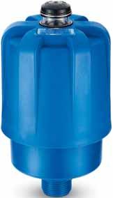
SERIES. Maximum pressure 8 bar
 SERIES Maximum pressure 8 bar F l o w r a t e s t o 0 0 l / m i n OLD MPF 00 NEW MPF 00 8 75 80 5-6 5,5 5,5 Nr. holes Ø 8,5 55 55 Nr. slots Ø 8,5 Up to: G NPT SAE 6 Up to: G / SAE 0 DIFFERENCE BETWEEN...
SERIES INLINE FILTERS LMP 210. Maximum pressure 60 bar Maximum flow to l / mi n
 SERIES INLINE FILTERS LMP 0 Maximum pressure 60 bar Maximum flow to 0 0 l / mi n SERIES LMP 0 Working pre s s u re 60 bar Style S Style B B B D.I. D.I. A A Technical data Filter housing ( M a t e r i a
Maximum pressure 80 bar
 Maximum pressure 80 bar F l o w r a t e s t o 0 0 l / m i n LMP 0 Maximum pressure 80 bar F l o w r a t e s t o 6 0 l / m i n Technical data LMP 0 Filter housing (Materials) Head: luminium Housing: ataphoresis
Nylon oil filler and air breather filler caps
 Series TP 0 Dimensions 6 Bayonet G / TP0 (Materials) - Cover/ringnut: Nylon - Filter element: Impregnated paper Polyurethane - Pressurisation valve: Nylon Galvanised Steel - Seal: Reservoir holes - Flange:
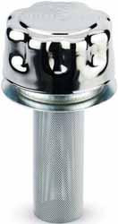
Metal air breather filter
 Series S Metal air breather filter 4 H 5 6 7 H H S (Materials) Screw: Galvanised Steel Washer: Teflon Cover: Steel 4 Filter element: Impregnated paper 5 Ring: Galvanised Steel 6 Seal: R 7 Connection: nodised
LMP 210. Style B. Style S. Maximum pressure 60 bar F l o w r a t e s t o l / m i n
 LMP 0 Style S Style Maximum pressure 60 bar F l o w r a t e s t o 7 0 l / m i n 6 Technical data Filter housing (Materials) Head: luminium Housing: nodised luminium ypass valve: Nylon - Steel Pressure
Flow rates to 590 l/min
 LM 400-40 - 4 Maximum pressure bar Flow rates to 590 l/min Technical data housing (Materials) ead: nodized luminium ousing: nodized luminium Manifolds: Steel - Painted black ypass valve: Steel -way ball
SERIES FMP. Working pressure. 280 bar. Style D Style V Style Z. Style T. Style B. Style S B B D.I. D.I. D.I. D.I. D.I. D.I.
 6 FMP SERIES FMP Working pressure 80 bar Style S Style Style T Style D Style V Style Z 7 Technical data Filter body (Materials) ead: Cast iron (chemical heat treatment) ousing: Cast iron (chemical heat
Working pressure. 420 bar. Style T. Style B. Style D Style V Style Z. Style S B B D.I. D.I. D.I. D.I. D.I. D.I.
 5 FP SRIS FP Working pressure 40 bar Style S Style Style T Style D Style V Style Z 5 Technical data Filter body (Materials) ead: Cast iron (chemical heat treatment) ousing: Steel (chemical heat treatment)
PRESSURE GAUGE SELECTORS
 PRESSURE GUGE SELECORS Gauge isolator valves are designed to protect pressure gauges from pressure shocks when the pressure reading is not required; after each reading setting the selector to the closed
Flow rates to 750 l/min
 FP Maximum pressure 0 bar Flow rates to 70 l/min Technical data Filter housing (Materials) ead: Cast iron (chemical heat treatment) ousing: Steel (chemical heat treatment) Bypass valve: AISI L (FP 00-0)
Flow rates to 750 l/min
 FP Maximum pressure 0 bar Flow rates to 70 l/min Technical data Filter housing (Materials) ead: Cast iron (chemical heat treatment) ousing: Steel (chemical heat treatment) Bypass valve: AISI L (FP 0-0)
Working pressure. 320 bar. Style T. Style D. Style S. Style B B B D.I. D.I. D.I. D.I.
 8 FB SERIES FB Working pressure 0 bar Style S Style B Style T Style D B B B B D.I. D.I. D.I. D.I. A A A A 8 Technical data Filter body (Materials) ead: Cast iron (chemical heat treatment) ousing: Steel
Flow rates to 485 l/min
 FB Maximum pressure 0 bar Flow rates to 8 l/min Technical data Filter housing (Materials) ead: Cast iron (chemical heat treatment) ousing: Steel (chemical heat treatment) Bypass valve: Steel Check valve:
Maximum pressure 420 bar Flow rate to 152 l/min. 560 bar. 140 l/min. Flow rate l/min FMM 050 1/2 1,50 3/4 1,00. Δp bar 0,50 0,00 FHA 051 1,50 1,00
 FMM 00 Maximum pressure 0 bar Flow rate to l/min FHA 0 Maximum pressure 60 bar Flow rate to 0 l/min Technical data FMM 00 Filter housing (Materials) Head: Cast iron (chemical heat treatment) Housing: Steel
Flow rates to 485 l/min
 FB Maximum pressure 0 bar Flow rates to 8 l/min Technical data Filter housing (Materials) ead: Cast iron (chemical heat treatment) ousing: Steel (chemical heat treatment) Bypass valve: Steel Check valve:
Flow rates to 485 l/min
 FB Maximum pressure 0 bar Flow rates to 8 l/min Technical data Filter housing (Materials) ead: Cast iron (chemical heat treatment) ousing: Steel (chemical heat treatment) Bypass valve: Steel Check valve:
FMM 050 uk :26 Pagina 5 (1,1) FMM 050
 FMM 050") uk 6-07-006 9:6 Pagina 5 (,) 30 uk 6-07-006 9:6 Pagina 5 (3,) SRIS Working pressure 80 bar Style S Style Style T Style D 3 uk 6-07-006 9:6 Pagina 7 (,) Technical data Filter body ( M a t e r i a l s )
uk 6-07-006 9:6 Pagina 5 (,) 30 uk 6-07-006 9:6 Pagina 5 (3,) SRIS Working pressure 80 bar Style S Style Style T Style D 3 uk 6-07-006 9:6 Pagina 7 (,) Technical data Filter body ( M a t e r i a l s )
Flow rates to 475 l/min
 FMP Maximum pressure 0 bar Flow rates to 7 l/min Technical data PRSSUR FILTR Filter housing (Materials) ead: Cast iron (chemical heat treatment) ousing: Steel (chemical heat treatment) Bypass valve: Brass
Polígono Indutrial O Rebullón s/n Mos - España -
 FP 5 Polígono Indutrial O Rebullón s/n. 646 - Mos - spaña - rodavigo@rodavigo.com SRIS FP Working pressure 40 bar Style S Style Style T Style D Style V Style Z 5 Polígono Indutrial O Rebullón s/n. 646
MPT Multifunction Multiport
 MP Multifunction Multiport Maximum pressure 8 bar F l o w r a t e s t o 0 0 l / m i n echnical data housing (Materials) ead: luminium Cover: Nylon Bowl: Nylon Pressure Working pressure: 8 bar emperature
FMP :41 Pagina 5 (1,1) FMP
 FMP") FMP 6-07-006 9:4 Pagina 5 (,) FMP 6 FMP 6-07-006 9:4 Pagina 5 (,) SERIES FMP Working pressure 80 bar Style S Style Style T Style D Style V Style Z 7 FMP 6-07-006 9:4 Pagina 7 (,) Technical data Filter
FMP 6-07-006 9:4 Pagina 5 (,) FMP 6 FMP 6-07-006 9:4 Pagina 5 (,) SERIES FMP Working pressure 80 bar Style S Style Style T Style D Style V Style Z 7 FMP 6-07-006 9:4 Pagina 7 (,) Technical data Filter
Element description. Multipass test in compliance ISO Contaminant ISO MTD. A - Microfibre
 Style FZ Stainless Steel Pressure filter Technical data element Style In-Line filter: FZ 00-0 FZP 0 FZ 0 FZP 6 FZX 0 Manifold mounting: FZ 0 FZM 0 Max. working pressure: 700 bar Max. working pressure:
Polígono Indutrial O Rebullón s/n Mos - España -
 FB 8 Polígono Indutrial O Rebullón s/n. 646 - Mos - España - rodavigo@rodavigo.com SERIES FB Working pressure 0 bar Style S Style B Style T Style D B B B B D.I. D.I. D.I. D.I. A A A A 8 Polígono Indutrial
STAINLESS STEEL FILTER
 STINLSS STL FILTR Style FZ Stainless Steel Pressure filter Technical data Style In-Line filter: FZ 00-0 FZP 0 FZ 0 FZP 6 FZX 0 Manifold mounting: FZ 0 FZM 0 Max. working pressure: 700 bar Max. working
High Pressure fi lters. FMP series. Maximum pressure up to 320 bar - Flow rate up to 475 l/min. High Pressure fi lters
 High Pressure fi lters FMP series Maximum pressure up to 0 bar Flow rate up to 7 l/min High Pressure fi lters FILTER SIZING The correct filter sizing have to be based on the variable pressure drop depending
387 Low & Medium Pressure filters
 Low & Medium Pressure fi lters LMD 000 & series Maximum pressure up to 6 bar Flow rate up to 90 l/min 87 Low & Medium Pressure filters FILTER SIZING The correct filter sizing have to be based on the variable
Return fi lters. FRI series. Maximum pressure up to 20 bar - Flow rate up to 1500 l/min. Return fi lters
 Return fi lters FRI series Maximum pressure up to 0 bar - Flow rate up to 500 l/min 9 Return fi lters FILTER SIZING The correct filter sizing have to be based on the variable pressure drop depending by
mandata_us :43 Pagina 83 (1,1) FHB 82
 FHB 82") 8 FHB SERIES FHB Working pressure 4600 psi Style S Style B Style T Style D B B B B D.I. D.I. D.I. D.I. A A A A 8 Technical data Filter body ( M a t e r i a l s ) Head: Cast iron (chemical heat tre a t
8 FHB SERIES FHB Working pressure 4600 psi Style S Style B Style T Style D B B B B D.I. D.I. D.I. D.I. A A A A 8 Technical data Filter body ( M a t e r i a l s ) Head: Cast iron (chemical heat tre a t
High Pressure fi lters. FMP 039 series. Maximum pressure up to 110 bar - Flow rate up to 80 l/min. High Pressure fi lters
 High Pressure fi lters FMP 09 series Maximum pressure up to 0 bar Flow rate up to 80 l/min 7 High Pressure fi lters FILTER SIZING The correct filter sizing have to be based on the variable pressure drop
High Pressure fi lters
 High Pressure fi lters FMM 00 series Maximum pressure up to 0 bar Flow rate up to l/min FHA 0 series Maximum pressure up to 60 bar Flow rate up to 0 l/min 9 High Pressure fi lters FILTER SIZING The correct
LMP series Filter element according to DIN Maximum pressure up to 30 bar - Flow rate up to 2000 l/min
 Low & Medium Pressure fi lters LMP 90090 series according to DIN 0 Maximum pressure up to 0 bar Flow rate up to 000 l/min Low & Medium Pressure filters FILTER SIZING The correct filter sizing have to be
331 Low & Medium Pressure filters
 Low & Medium Pressure fi lters LMP 00-0 & 0- series Maximum pressure up to 60 bar - Flow rate up to 70 l/min Low & Medium Pressure filters FILTER SIZING The correct filter sizing have to be based on the
379 Low & Medium Pressure filters. LMD 211 series. Maximum pressure up to 60 bar - Flow rate up to 330 l/min. Low & Medium Pressure fi lters
 Low & Medium Pressure fi lters LMD series Maximum pressure up to 60 bar Flow rate up to 0 l/min 79 Low & Medium Pressure filters FILTER SIZING The correct filter sizing have to be based on the variable
High Pressure fi lters. FHB series. Maximum pressure up to 320 bar - Flow rate up to 485 l/min. High Pressure fi lters
 High Pressure fi lters FHB series Maximum pressure up to 0 bar - Flow rate up to 8 l/min 8 High Pressure fi lters FILTER SIZING The correct filter sizing have to be based on the variable pressure drop
High Pressure fi lters. FHM series. Maximum pressure up to 320 bar - Flow rate up to 450 l/min. High Pressure fi lters
 High Pressure fi lters FHM series Maximum pressure up to 0 bar - Flow rate up to 0 l/min 67 High Pressure fi lters FILTER SIZING The correct filter sizing have to be based on the variable pressure drop
359 Low & Medium Pressure filters. LMP series. Maximum pressure up to 30 bar - Flow rate up to 2400 l/min. Low & Medium Pressure fi lters
 Low & Medium Pressure fi lters LMP 909 series Maximum pressure up to 0 bar Flow rate up to 00 l/min 9 Low & Medium Pressure filters FILTER SIZING The correct filter sizing have to be based on the variable
MPF SERIES RETURN FILTER
 MPF SERIES The series of filters MPF has specifically been designed for use on mobile applications, agricultural machinery and power units. The MPF filter range is suitable for flow rates up to 750 l/min.
High Pressure fi lters. FHB series. Maximum working pressure up to 32 MPa (320 bar) - Flow rate up to 485 l/min
 - Flow rate up to 485 l/min") High Pressure fi lters FHB series Maximum working pressure up to MPa (0 bar) - Flow rate up to 8 l/min High Pressure fi lters Introduction FILTER SIZING INDEX CALCULATION CORRECTIVE FACTOR Page Introduction
High Pressure fi lters FHB series Maximum working pressure up to MPa (0 bar) - Flow rate up to 8 l/min High Pressure fi lters Introduction FILTER SIZING INDEX CALCULATION CORRECTIVE FACTOR Page Introduction
Suction fi lters. SF series. Flow rate up to 160 l/min. Suction fi lters
 Suction fi lters SF 00 series Flow rate up to 60 l/min Suction fi lters FILTER SIZING The correct filter sizing have to be based on the variable pressure drop depending by the application. For example,
High Pressure fi lters. FHA 051 series. Maximum working pressure up to 56 MPa (560 bar) - Flow rate up to 140 l/min. High Pressure fi lters
 - Flow rate up to 140 l/min. High Pressure fi lters") High Pressure fi lters FHA 0 series Maximum working pressure up to 6 MPa (60 bar) Flow rate up to 0 l/min 99 High Pressure fi lters Introduction FILTER SIZG DEX CALCULATION CORRECTIVE FACTOR Page Introduction
High Pressure fi lters FHA 0 series Maximum working pressure up to 6 MPa (60 bar) Flow rate up to 0 l/min 99 High Pressure fi lters Introduction FILTER SIZG DEX CALCULATION CORRECTIVE FACTOR Page Introduction
Return fi lters. MPI series. Maximum working pressure up to 1 MPa (10 bar) - Flow rate up to 3000 l/min
 - Flow rate up to 3000 l/min") Return fi lters series Maximum working pressure up to MPa (0 bar) Flow rate up to 000 l/min 0 Return fi lters Introduction FILTER SIZING INDEX CALCULATION CORRECTIVE FACTOR Page Introduction Calculation
Return fi lters series Maximum working pressure up to MPa (0 bar) Flow rate up to 000 l/min 0 Return fi lters Introduction FILTER SIZING INDEX CALCULATION CORRECTIVE FACTOR Page Introduction Calculation
E 094 E 103 E 143. Tank top mounting Connection up to G1 Nominal flow rate up to 135 l/min e
 R e t u r n F i l t e rs E 094 E 103 E 143 Tank top mounting Connection up to G1 Nominal flow rate up to 135 l/min 20.30-5e D e s c r i p t i o n Application In the return line circuits of hydraulic systems.
Cartridge Valves Technical Information. Quick reference
 Quick reference Contents CPF0... 8. CP600-5... 8. CP60-5... 8. 066 handle kit... 8.5 MP06... 8.6 MP... 8.6 X05-FD0 Traction manifold... 8.9 X05-FD6 Traction manifold... 8.0 X05-FD0 Traction manifold...
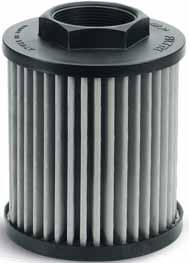
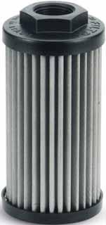
Spin-on fi lters. MPS series. Maximum pressure up to 12 bar - Flow rate up to 365 l/min. Spin-on fi lters
 Spin-on fi lters MPS series Maximum pressure up to bar - Flow rate up to 65 l/min 6 Spin-on fi lters FILTER SIZING The correct filter sizing have to be based on the variable pressure drop depending by
Suction fi lters. MPA - MPM series. Flow rate up to 875 l/min. Suction fi lters
 Suction fi lters & MPA MPM series Flow rate up to 87 l/min 7 Suction fi lters FILTER SIZING The correct filter sizing have to be based on the variable pressure drop depending by the application. For example,
Air Cooler Industry AC-LN 1-7 / ACA-LN 2-7 / ACAF-LN 2-7
 ir ooler Industry -LN -7 / -LN -7 / F-LN -7 Symbol General The -LN -7 air cooler series can be used in all areas where either oil or water-glycol is to be cooled with air. The coolers with an axial fan
A wide selection of pipe and orifice sizes is offered. Valves are available with threaded ports in brass and stainless steel.
 Solenoid Valve Waterhammer-Free, 0- PSI /-Way; NPT - NPT; 0- PSI Advantages/Benefits Type 63 Waterhammer-free Low noise Zero differential pressure ompact design with high flow rates Low maintenance oil
Check-Q-meter. Table of contents. Features. Functions. RE 27551/ /10 Replaces: Type FD
 Check-Q-meter RE /0.0 /0 Replaces: 09.9 Type FD Nominal size... Series ax. Operating pressure 0 bar ax. Flow 0 l/min K9/ Table of contents Contents Page Features Functions Ordering details Symbols Functional
Differential indicators
 Differential indicators 5-07-006 7:8 Pagina 5 (,) Differential indicators A guarantee of maintenance to the correct ISO 06 contamination class achieved through the use of the filters can be provided exclusively
High-efficiency Circulator Pump. Rio-Eco N / Rio-Eco Z N. Type Series Booklet
 High-efficiency Circulator Pump Rio-Eco N / Rio-Eco Z N Type Series Booklet Legal information/copyright Type Series Booklet Rio-Eco N / Rio-Eco Z N KSB Aktiengesellschaft All rights reserved. The contents
Its modular concept allows to build up a ball valve for any degree of automation and any kind of application
 Type 2657...59 DN 10 up to 80 mm; Plastic; 2/2 way dvantages/benefits ntegrated pilot valves, position feed-back and limit switches available Customized system solutions with Burkert valves & sensors With
Direct-operated 2/2-way solenoid valves Type EV210B
 Data sheet Direct-operated 2/2-way solenoid valves Type EV20B EV20B covers a wide range of direct-operated 2/2-way solenoid valves for universal use. EV20B is a very robust valve program with high performance
5. DRIVE 1. SAFETY 2. PREPARATION 3. FRAME 4. TRANSMISSION 6. ROW UNIT 7. OPTIONAL EQUIPMENT
 TABLE OF CONTENTS 1. SAFETY 2. PREPARATION 3. FRAME 4. TRANSMISSION 5. DRIVE 6. ROW UNIT 7. OPTIONAL EQUIPMENT DRIVE Standard Turbofan 540, 450 & 1000 RPM with PTO Drive Your Monosem planter will be equipped
VOLUMEC. Valve Position Indicator 5
 VOLUMEC Valve Position Indicator 5 2 KRACHT CORP. 8600 S Wilkinson Way Unit A Perrysburg, OH 43551 USA P +1 419 874 1000 F +1 419 874 1006 flowmeters@krachtcorp.com www.krachtcorp.com VOLUMEC Valve Position
PN LINE. PN Line. PX Line. PA Line. PU Line PX LINE. PV Line PA LINE & TUBINGS PU LINE PV LINE. Brass Push-in fittings
 I NDEX PV LINE PX LINE PU LINE PA LINE & TUBINGS PN LINE Brass Push-in fittings Stainless Steel Push-in fittings Brass Standard fittings and Flexible Hoses Couplings and Multiple Connectors Function fittings
Cooler-Bypass Thermostat Valve, Size 10
 Cooler-Bypass Thermostat Valve, Size Q max = l/min, p max = bar Temperature-controlled, integral relief function Description These direct acting bypass thermostat valves are size, temperature controlled,
CMA - B - C - D - CMR
 Cast iron self-priming electric pumps. APPLICATIONS Pressure boosting domestic plants Small-scale irrigation Moving non-aggressive liquids for civil and industrial use Washing plants Washing vehicles CMA-B-C-D
HD 049 HD 069 HD 172 HD 319 HD 419 HD 619. Operating pressure up to 8700 psi Nominal flow rate up to gpm us
 H i g h P re s s u re i l t e r K i t s H 049 H 069 H 172 H 319 H 419 H 619 Operating pressure up to 8700 psi Nominal flow rate up to 118.9 gpm 40.95-3us e s c r i p t i o n pplication In the high pressure
CALEFFI. Modulating digital controller for heating and cooling. 161 series 01122/08 GB. replaces dp 01122/05
 Modulating digital controller for heating and cooling series REGI ERED SI EN ISO 00:000 Cert. n FM UNI EN ISO 00:000 Cert. n 000 0/0 G replaces dp 0/0 Function The controller can be used with three-point
M O D U L E - 3A Model A10V0 Piston Pump Manual A10V0 PUMP. Features
 T E C H N I C A L I N F O R M A T I O N M A N U A L F O R T H E A 1 0 V 0 V A R I A B L E D I S P L A C E M E N T P U M P S A10V0 PUMP Features High Efficiency through load sensing (= fuel savings) Maximum
KM-1600SWH KM-1600SRH KM-1600SWH3 KM-1600SRH3
 NO. ISSUED: REVISED: 71193 OCT. 2, 2001 JAN. 27, 2003 HOSHIZAKI STACKABLE CRESCENT CUBER MODELS KM-1600SWH KM-1600SRH KM-1600SWH3 KM-1600SRH3 PARTS LIST KM-1600SWH L-0 June, 2001 M-0 Feb., 2002 M-1 Feb.,
SINGLE IMPELLER CENTRIFUGAL ELECTRIC PUMPS in cast iron
 Cast iron self-priming electric pumps. APPLICATIONS Pressure boosting domestic plants Small-scale irrigation Moving non-aggressive liquids for civil and industrial use Washing plants Washing vehicles CMA-B-C-D
EVOTRON WET ROTOR ELECTRONIC CIRCULATORS TECHNICAL DATA APPLICATIONS ADVANTAGES
 TECNICAL DATA EVOTRON Operating range: from, -, m3/h with head of up to metres. Pumped liquid temperature range: from - C to + C. Working pressure: bar ( kpa). Protection class: IP X. Insulation class:
PARTS LIST GAS BOILERS MODELS: CG320 (E) CG325 (E) CG330 (E)
 CG325 (E) CG330 (E)") PARTS LIST GAS BOILERS MODELS: CG320 (E) CG325 (E) CG330 (E) CROWN FOOD SERVICE EQUIPMENT LTD. 70 OAKDALE ROAD, DOWNSVIEW, (TORONTO), ONTARIO, CANADA, M3N 1V9 TELEPHONE: (416) 746-2358, FAX: (416) 746-8324
PARTS LIST GAS BOILERS MODELS: CG320 (E) CG325 (E) CG330 (E) CROWN FOOD SERVICE EQUIPMENT LTD. 70 OAKDALE ROAD, DOWNSVIEW, (TORONTO), ONTARIO, CANADA, M3N 1V9 TELEPHONE: (416) 746-2358, FAX: (416) 746-8324
Cooling Water Flow Regulator
 Temperature controlled, indirectly and directly actuated diaphragm valves / seat valves Port size G 3/8 to G DN 0 to DN 0 ontinuous regulation High accuracy No auxiliary energy required Technical data
IBV Series C Carbon Steel Inverted Bucket Vertical Steam Trap
 Local regulations may restrict the use of this product to below the conditions quoted. In the interests of development and improvement of the product, we reserve the right to change the specification without
IBV Series Z Alloy Steel Inverted Bucket Vertical Steam Trap
 Local regulations may restrict the use of this product to below the conditions quoted. In the interests of development and improvement of the product, we reserve the right to change the specification without
Flow Divider Type MH2FA, Series 4X (Differential lock) Size 12 to 32 up to 420 bar up to 300 L/min
 Size 12 to 32 up to 420 bar up to 300 L/min") RE 8/0.98 8/0.9 Flow Divider Type MHF, eries X (Differential lock) ize to up to 0 bar up to 00 /min RE 8/0.98 Replaces: 0.9 Characteristics: Double-acting (dividing and summating) flow divider Fixed division
RE 8/0.98 8/0.9 Flow Divider Type MHF, eries X (Differential lock) ize to up to 0 bar up to 00 /min RE 8/0.98 Replaces: 0.9 Characteristics: Double-acting (dividing and summating) flow divider Fixed division
Commercial Generator Parts Catalog. PROTEC Series
 Commercial Generator Parts Catalog PROTEC Series YD ÁÁ ÁÁ To avoid errors or delay in filling your parts order, always give the MODEL, SPEC NO. and SERIAL NO. from the Onan nameplate. For handy reference,
Made in Italy HOSE REELS CATALOGUE TECHNOLOGY FOR FLUIDYNAMICS. No. E14/A1
 Made in Italy HOSE REELS CATALOGUE TECHNOLOGY FOR FLUIDYNAMICS No. E14/A1 The complete range of our products is presented in the specific catalogues: HOSE REELS CATALOGUE No. E14/A2 HOSE REELS CATALOGUE
PR CYCLONE SECONDARY SHUTOFF
 EN PR CYCLONE SECONDARY SHUTOFF ORIGINAL INSTRUCTIONS CYCLONE SECONDARY SHUTOFF PR530 CYCLONE SECONDARY SHUTOFF PR330 CYCLONE SECONDARY SHUTOFF PR200-250 CYCLONE SECONDARY SHUTOFF PR150 TECHNICAL DATA
5/2-5/3 SPOOL VALVES MULTIFUNCTION air operated or solenoid air operated with subbase ISO 5599/1 sizes 1, 2 and 3
 / - / SPOOL VALVES MULTIFUNCTION air operated or solenoid air operated with subbase ISO 99/ sizes, and Series Fluids air or inert gas, filtered, lubricated or not Operating pressure Pilot pressure Ambient
Series P0 Electronic Metering Pump. Specification Sheet and Assembly Details Manual No : 1934, 1843 Rev. : C, D Rev. Date : 6/01, 10/2015
 INJECTION CHECK VALVE COUPLING NUT DISCHARGE TUBING 4 FUNCTION VALVE SPACER, E.P.U PUMP HEAD RETURN LINE (PRESSURE RELIEF) METERING PUMP HOUSING STROKE KNOB SUCTION FITTING SUCTION TUBING WEIGHT POWER
Conductivity sensor for hygienic applications
 Conductivity sensor for hygienic applications Type 8221 can be combined with Perfect for demanding applications in the hygienic industry (CIP and SIP compatible) Variants available for usage over a wide
DMP 331P. Industrial Pressure Transmitter. Process Connections With Flush Welded Stainless Steel Diaphragm
 DMP P Industrial Pressure Transmitter Process Connections With Flush Welded Stainless Steel accuracy according to IEC 60770: standard: 0.5 % FSO option: 0.5 % FSO Nominal pressure from 0... 00 mbar up
Universal type Port size AS13 1F-M3. M3 x 0.5 M5 x 0.8 AS23 1F-01 AS23 1F-02 AS33 1F-02 AS33 1F-03 AS43 1F-04 R 1/8 R 1/4 R 1/4 R 3/8 R 1/2
 Minimizes installation time and cost Reduces the mounting height and enables compact machinery design. Effective area is larger than the former model. Tube swivels 0 Universal type permits 0 piping swivel.
AME Model. (1) Rated flow (l/min (ANR)) Port size (Nominal size B) Weight (kg)
 Rated flow (l/min (ANR)) Port size (Nominal size B) Weight (kg)") Super Mist Separator Series AME Series AME separates and absorbs aerosol state fine oil particles in compressed air and changes the oil lubricating compressed air to oilless equivalent air. It should be
Super Mist Separator Series AME Series AME separates and absorbs aerosol state fine oil particles in compressed air and changes the oil lubricating compressed air to oilless equivalent air. It should be
Mounting kits for insulation of power transistors
 ounting kits for insulation of power transistors tel. 0..6.6.6 www.elitaliaweb.it fax 0.6.6.0.09 info@elitaliaweb.it ST STS ST 0 STS 0 for transistor TO TO TO 0 TO 0 version with mica wafer S with silicone
DS 300. Electronic Pressure Switch. with IO-Link interface. Stainless Steel Sensor. accuracy according to IEC 60770: 0.35 % FSO.
 DS 00 Electronic Pressure Switch with IO-Link interface Stainless Steel Sensor accuracy according to IEC 60770: 0.5 % FSO Nominal pressure from 0... 00 mbar up to 0... 600 bar Digital output signal IO-Link
Spare parts list UC-S
 Spare parts list UC-S Contents Water inlet and tank heating Water softener Water drain, Mediamat Cyclo Circulating pump Wash + rinse; bottom Wash + rinse; top Boiler Dosage Panelling Cover plate, electrical
DN 1/4" to 4" Male, Female BSP - 10 C C Max Pressure : 40 Bars Specifications : Anti blow-out stem PTFE packing Full bore.
 Size : Ends : Min Temperature : Max Temperature : DN 1/4" to 4" Male, Female BSP - 10 C + 120 C Max Pressure : 40 Bars Specifications : Anti blow-out stem PTFE packing Full bore Materials : Brass Page
K 080/12 F 10 K 3-2X/.. Features
 RE 2 1/11.02 Replaces: 0.2 Fine throttle Type F Nominal sizes and Series 2X and 3X Maximum operating pressure 2 bar Maximum flow 0 L/min K 00/12 F K 3-2X/.. K 0/ F P 3-3X/.. Overview of contents Contents
PARTS LIST E Qty. Description Alternative Price Q.ty per pck.
 Page 1 R50010327-3 MOTOP.PARTNER'96 230-240/50 110 H90 VALV.COMP.IN.1,8 X FKX E50010001-02 Qty. Alternative Price Q.ty per 007 4.008.0583 10 2 1 MOTOR FAN COVER '96 WITHOUT GRILL 0 0 008 3.099.0049 10
Amphenol C 091 A/B/D. Circular Connectors. Amphenol-Tuchel Electronics GmbH
 Amphenol C 091 A/B/D Circular Connectors Amphenol-Tuchel Electronics GmbH General information These connectors are designed and produced in conformity with the low-voltage directive (/3/EWG) respectively
barmesapumps.com SELF-PRIMING CENTRIFUGAL TRASH PUMP SPECIFICATIONS Series: SH8-U Suction: 8" Discharge: 8" Spherical solids handling: 3"
 SELF-PRIMING CENTRIFUGAL TRASH PUMP Series: SH-U Suction: " Discharge: " Spherical solids handling: 3" SIZE BEARING - PUMP END " x " NPT, lbs., female flange. Open single ball, radial load. LIQUID TEMPERATURE
DN 1/4" to 4" Male, Female BSP - 10 C C Max Pressure : 30 Bars (up to DN1") Specifications : Anti blow-out stem PTFE packing Full bore
 Specifications : Anti blow-out stem PTFE packing Full bore") Size : Ends : Min Temperature : Max Temperature : DN 1/4" to 4" Male, Female BSP - 10 C + 120 C Max Pressure : 30 Bars (up to DN1") Specifications : Anti blow-out stem PTFE packing Full bore Materials
Size : Ends : Min Temperature : Max Temperature : DN 1/4" to 4" Male, Female BSP - 10 C + 120 C Max Pressure : 30 Bars (up to DN1") Specifications : Anti blow-out stem PTFE packing Full bore Materials
Vortex Flow Meters. RVL Series Vortex Flow Meter
 TM Vortex Meters RVL Series Vortex Meter pplications: Water/Wastewater I Water: Semiconductor, Institutional I Water Skids Semiconductor Equipment Slurry hemical Processing RINE FEERTE IN. ISO 900 : 000
Repair Parts List DUEL FUEL RANGE MODEL NUMBER SVD48600BC. When requesting service or ordering parts, always provide the following information:
 Repair Parts List DUEL FUEL RANGE MODEL NUMBER SVD48600BC When requesting service or ordering parts, always provide the following information: - Product Type - Part Number - Model Number - Part Description
VDN2.. VEN2.. VUN2.. Radiator valves. Building Technologies HVAC Products ACVATIX TM. NF norm, for 2-pipe heating systems
 06 EN - Straight valves VDN.. Angle valves VEN.. Reverse angle valves VUN.. ACVATIX TM Radiator valves NF norm, for -pipe heating systems VDN.. VEN.. VUN.. Valve bodies made of brass, mat nickel-plated
Parts List with Exploded Views
 Parts List with Exploded Views Dual Fuel- Series Dual Fuel Range Top Parts List for Model DF Ref # Part # Description 0 Grate, Burner W/Rubber Pad 0 Burner Cap Assy, Sml 0 Burner Head 0 Venturi, Small
VD1 CLC. Small Valves DIN-range with a higher k v -value
 0 EN - Small Valves DIN-range with a higher k v -value VD CLC Valve body made of brass, mat nickel-plated DN, DN 0 and DN Internally and externally threaded (Rp / R) conforming to ISO 7- Manual knob /
Absolute encoders multiturn
 elektronischer electronic multiturn, Multiturn, magnetic magnetisch Sendix M66 / M68 (shaft / hollow shaft) The Sendix M6 with Energy Harvesting Technology is an electronic multiturn encoder in miniature
Part /Assy Parts List. Production Order. Badge, Perkins/Sabre M215C. Description
 Badge, Perkins/Sabre M215C Part /Assy 5242 S000000 0002 2 X X 33213 BADGE, HEADER TANK, PERKINS/SABRE M21 S000000 1 P Badge, manifold, Perkins/Sabre(34314) Part /Assy 6696 S000000 0001 1 X X 34314 BADGE,