THE RETARDATION METHOD
|
|
|
- Stella Higgins
- 5 years ago
- Views:
Transcription


1 EFFICIENCY BY THE RETARDATION METHOD by E. C. DOBB1E W. W. DREW G. E. WILLIAMS L. L. WILLIAMS ARMOUR INSTITUTE OF TECHNOLOGY , 7 D65

2 Illinois Institute of Technology Libraries

3 AT 211 Dobbie, Edward C. Efficiency by the retardation method

4

5


6 ;.>...


7 EFFICIENCY BY THE RETARDATION METHOD A THESIS PRESENTED BY EDWARD C. DOBBIE WALTER W. DREW GUY E. LYTLE L. TO THE WILLIAMS WILLIAMS PRESIDENT AND FACULTY ARMOUR INSTITUTE OF TECHNOLOGY FOR THE DEGREE OF BACHELOR OF SCIENCE IN ELECTRICAL ENGINEERING HAVING COMPLETED THE PRESCRIBED COURSE OF STUDY IN ELECTRICAL ENGINEERING may ion ILLINOIS INSTITUTE OF TECHNOLOGY PAUL V.GALVIN LIBRARY? WEST 33RD street ±Y±J± X 1_0±± CHICAGO. IL 60616

8
. Swenaon and Frankenfield, Vol.")
. Standard Handbook, Sec. 7, Art. 258.")
9 BIBLIOGRAPHY. (1). Karapetoff, pp (2). Swenaon and Frankenfield, Vol. 2, pp (3). Smith, Vol. 2, p 231. (4). Standard Handbook, Sec. 7, Art

10 -CRT < i,s.lov, rsg


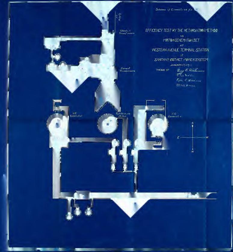
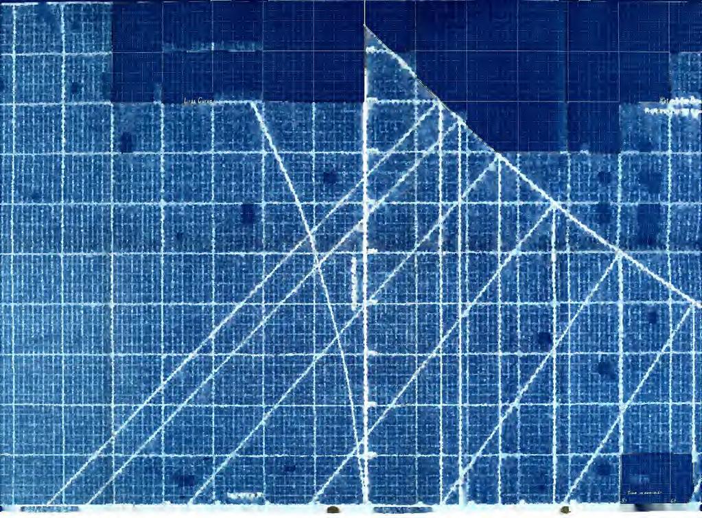
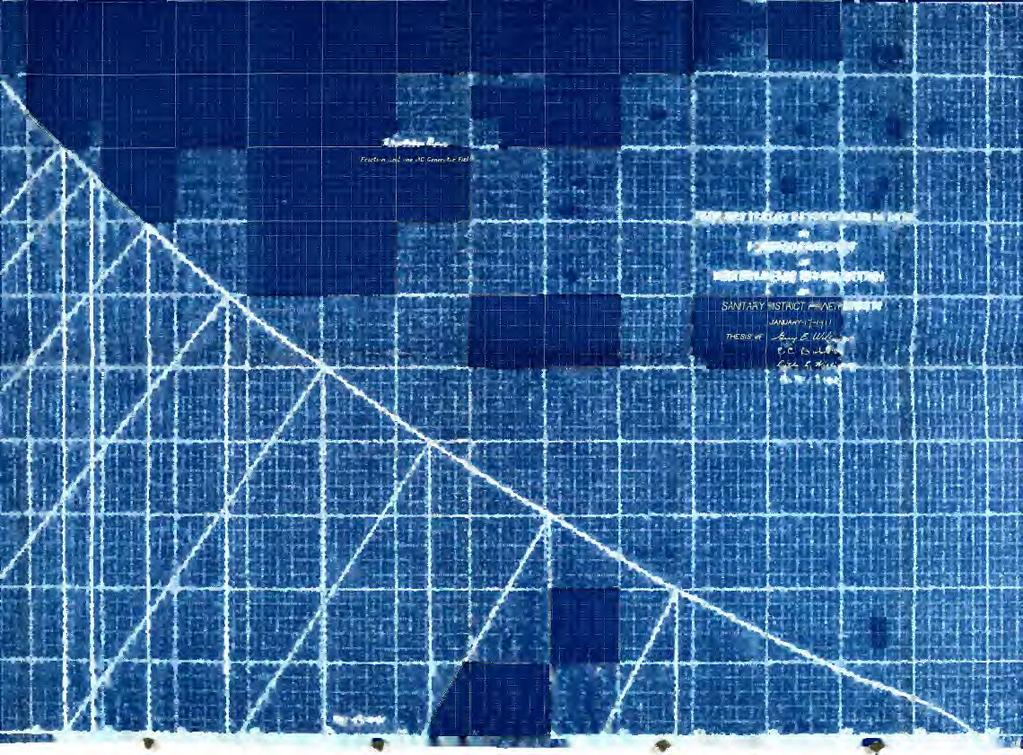
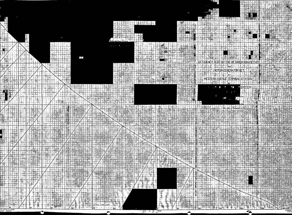
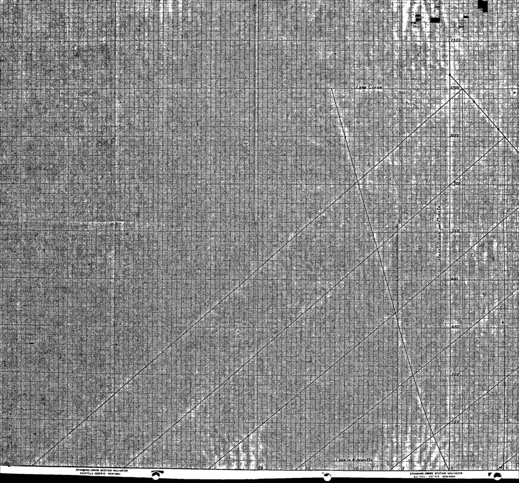
11 INDEX. Page THEORY 1-8 Retardation Constant 3 Retardation Curve 4 Determination of Retardation Constant 5 Efficiency 8 METHOD OF PROCEEDURE 9-15 Retardation Runs 11 Constancy of Short Circuit Current 13 EFFICIENCY FORMULA 16 CALCULATIONS RATINGS 21 Plate Scheme of Connections 1 Ret. Curve, No Fields 2 Ret. Curve, One D.C. Field Only 3 Ret. Curve, A.C. Field Only 4 Ret. Curve, A.C. Motor Short Circuited 5 All Retardation Curves 6 Total Loss Curves 7 Efficiency Curve 8 Direct Current Saturation Curve 9 Alternating Current Sat. and Short Circuit Curves 10

12 '


13 . THEORY A very convenient method of determin*- ing the efficiency of a generator or motor is the retardation method. The maohine is brought to its highest safe speed, the excitation is adjusted to that value which it normally has at the load at which the efficiency is desired, the driving power is cut off without disturbing the excitation, and the machine gradually slows down as its stored kinetic energy is overcome by the iron and friction losses. The instantaneous speeds are measured at intervals throughout the retardation and a Retardation Curve is plotted with speeds as ordinates and times as abscissae. Runs are taken with different values of excitation and other retardation curves are plotted. From these curves we obtain the

14 - ' : ' - - ' ' - ' I ' ' - -

15 . ~2~ Effioiency Curve as will be explained later. This method does not give reliable re~ suits when applied to small machines, because they slow down too quickly; but with large machines, where the moment of inertia is considerable, the results are very satisraotory The energy E stored in a body rotating with an angular velocity u) is > E = 1/2 W K (1) where K is the moment of inertia of the body. It is difficult to calculate the moment of inertia of a body such as an armature so that it is desirable to transform equation (1) into one that is more convenient. The angular velocity <-0 is proportional to n, the speed in revolutions per minute, or <>> = a n where a is a constant. Substituting we obtain

16 ',


17 -3- E = 1/2 a 2 n s K and since K is a constant E = 1/2 n 2 (2) where C is a constant proportional to the moment of inertia K. The kinetic energy stored in the rotating armature is reduced by the iron and friction losses only. Hence the rate of change of stored energy is a measure of the iron and friction losses W, so that and C n 2 d **» 2 W = (3) dt W dt = d C n 2 (4) 2 which expresses that the decrease in kinetic energy, during the infinitesimal time dt, is equal to the work performed by the armature in the same interval in overcoming the losses W. Differentiating we obtain


18 '.
 or")
")
19 -.4 W dt = C n dn (5) or W = C n dt dn (6) Figure 1.


20
 Therefore D B = A B tan A C B (8) dn = n»")

21 -5- In the retardation curve shown in Figure 1 the ratio dn/dt is the tangent of the angle A C B, the line A being tangent to the retardation curve at the point A where the speed is iii If A B is normal to the curve, the angle D A B is equal to the angle A C B and D B A B = tan D A B = tan A C B (7) Therefore D B = A B tan A C B (8) dn = n» (9) dt Hence we see that D B, which is known as the subnormal, is numerically equal to dn n -- dt and I = C (D B) (10) or the instantaneous loss W at a speed n ib proportional to the length of the subnormal to the retardation curve at the point where the speed is n«having made the retardation runs we determine the value of the constant C by either

22 -- E


23 -6- of two methods, (1) The value of the loss W is determined. (2) The value of the loss W is changed by a known amount w. In the first method we select one of the retardation curves, and using the same value of excitation as was used in obtaining this curve, we drive the machine, either electrlcally or mechanically, at a constant speed n, measuring the armature power input. If driven mechanically, loss W is of course the iron and friction the armature power input, which in turn is the output of the driving machine. This driving machine may conveniently be a calibrated motor. If driven electrically as a motor, the armature power input must be diminished by the armature copper loss to obtain the iron and friction Iosb W. We next measure the length of the subnormal to the retardation curve at the point where the speed is n. Knowing W and the length of the subnormal we can calculate C from equation (10). In the second method we select a retardation curve and take an extra retardation run,

24 I, " - -

25 -7- using the same excitation as was used in obtaining the selected curve, but with an additional known load w put on the machine* We then have 1 = C (D B) (10) and W+ w = C (D-l B-l) (11) where D B and D 1 B^ are the subnormals to the selected and new retardation curves respectively at the same speeds n. Eliminating we get C = (12) D-lB-l - d b The load w may be obtained by closing the armature on an adjustable resistance and keeping the output constant by means of a wattmeter. Another method is to apply a prcny brake with a definite torque. With either method w can be kept constant throughout a limited range of speed only. This is unimportant as only one point on the curve is necessary.


26 . '


27 -8- The question is frequently asked, "Is the constant C the same for all values of excitation?". Obviously it is the same as it is dependent only on the moment of inertia of the rotating "body. Having obtained the retardation curves and the value of the constant C we proceed as follows to obtain the efficiency curve. At a point on each curve corresponding to the normal speed of the machine we construct the subnormal and measure it. Multiplying the lengths of these subnormals by the constant C gives us the iron and the friction losses corresponding to the different excitations. To these losses we add the corresponding armature and field copper losses; and knowing the outputs of the machine for the various excitations we calculate the efficiencies for the various outputs from the equation Output Efficiency = (13) Output -V- Total Losses

28 ' -

29 -9- METHOD OP PROCEEDURE. The retardation method, when applied to the particular set tested, "became rather in~ volved due to the unusual combination of machines. The set consists of a synchronous motor direct connected to two compound interpole direct current generators connected in series. These generators are exactly alike in construction and rating and are flat compounded, hence their shunt field currents are constant for all loads. Although assumed to be go, their excitations are not constant for all loads due to the effect of the series turnb. Therefore, in assuming that the iron loss is constant for all loads we are in error; but we can make no correction because of the unknown value of series excitation. Since the synchronous motor is used for power factor regulation, its excitation is variable, The conditions of the test made it impossible to determine the values of excitation throughout the range of load, for any assumed power factor. Therefore i$ was necessary to assume


30 '


31 -10. this excitation constant. Obviously, in making this assumption, we will obtain a total iron loss that is constant, which we know is not true. In taking the retardation runs the series connection of the direct current generators was broken and the set was started and brought to speed by means of the synchronous motor, which starts as an induction motor. When the synchronous motor was in step it was suddenly disconnected from the alternating current system, and one of the direct current generators, with its series field but not its interpole field, disconnected, was connected to a direct current source of supply. The direct current generator, operating as a shunt interpole motor, was then used to adjust the speed of the set to any desired value. The direct current supply system, not being of sufficient capacity for starting purposes, made it necessary to start by means of the synchronous motor.

32 -.'. 1 3
 Synchronous motor field only. (4) Synchronous motor short circuited with sufficient field to give full load current. The first run gave the total friction and windage loss.")
 from the total loss in run (2). The iron loss for both generators will then be twice this quantity.")
33 -11- Having brought the speed to the highest safe value, retardation runs were taken under the following conditions. (1) No fields. (2) One direct current generator field only. (3) Synchronous motor field only. (4) Synchronous motor short circuited with sufficient field to give full load current. The first run gave the total friction and windage loss. The second run gave the total friction and windage loss plus the iron loss of one direct current generator. This iron loss is obtained by subtracting the friction and windage loss in run (1) from the total loss in run (2). The iron loss for both generators will then be twice this quantity. The third run gave the total friction and windage loss plus the iron loss of the synchronous motor. This iron loss is obtained

34 - - '.. [
 from the total loss in run (4). The iron loss in this run is negligible because of the very small field.")
 the input is the sum of the friction and windage loss for the set, the iron loss for one direct current machine, and the armature copper loss for one direct current machine.")
35 12- "by subtracting the friction and windage lose in run (1) from the total loas in run (3). The fourth run gave the total friction and windage lose plus the synchronous motor armature copper loss. This armature copper loss is obtained by subtracting the friction and windage loss in run (1) from the total loss in run (4). The iron loss in this run is negligible because of the very small field. In runs (1) and (4) the inputs to the direct current machine, at normal speed, were measured before the machine was disconnected from the direct current supply system. In run (1) the input is the sum of the friction and windage loss for the set, the iron loss for one direct current machine, and the armature copper loss for one direct current machine. In run (4) the input is the sum of the friction and windage loss for the set, the iron loss for one direct current machine, the armature copper loss for one direct current machine, and the armature copper loss for the synchronous motor,

36 - ' ) -.' c I - ' r

 from the input of run (4) we obtain the magnitude of the synchronous motor armature copper loss.")
37 -13- neglecting the synchronous motor iron Iobs. The Inputs measured did not include any of the field copper losses. We are justified in assuming that the friction and windage loss of the set, the iron loss of one direct current machine, and the armature copper loss of one direct current machine are the same in both runs, because the increased losses in the direct current maohine, due to the short circuit current, are negligible. Therefore, subtracting the input of run (1) from the input of run (4) we obtain the magnitude of the synchronous motor armature copper loss. This Iosb is practically constant as shown below, so that we can obtain the constant C for the retardation curve by method (2), the additional known load w in equation (12) being the armature copper loss. In an alternating current circuit the current I is given by the equation


38 I ' - -
 J R 2 * (2 7Tf L) 2 The field to produce the short circuit current is very small, hence we are working on the straight part of the magnetization curve.")
39 -14- E I = -zz^z=z=^ (14) F R 2 * X 2 where E is the voltage, R the resistance, and X the reactance. The reactance is inductive so that X = 2TTf L (15) where f is the frequency and L the inductance. Therefore I E (16) J R 2 * (2 7Tf L) 2 The field to produce the short circuit current is very small, hence we are working on the straight part of the magnetization curve. This being so, E is proportional to f and E = b f (17) where b is a constant. Therefore

40 ' I - -
41 -15- I = -- - (18) I R 2 * (2TTf L) 2 In comparison with the reactance of the armature the resistance is very small for normal frequency and b I = (19) 27TL which is a constant.

42 '


43 -16- EPFICIENCY FORMULA. Let P-, = friction and windage loes of the set. Pg = iron Iobb of one direct current generator. P 3 = iron loss of synchronous motor. P4 = armature copper loss of one direct current generator. P 5 = armature copper loss of synchronous motor. P fi = field copper loss of one direct current generator. P = field copper loss of synchronous motor. Output Eff. =... «Output + P 1 4- P 2 P3 + 2P 4 + P 5 t 2P 6 f P?


44 I - - -
, normal speed. (D B) 34.5 cm. Length of subnormal, run (1), normal speed. (D^Bj^) 45.0 cm. From equation (12) w 2.954 = «= = 0.276 TJ 1 B 1 - D B 45-54.")
45 CALCULATIONS Determination of Constant C. See Plates (2) & (5) Input in run (1). Plate (2) KW. Input in run (4). Plate (5) KW. Difference, A.C. Motor copper loss w KW. Length of subnormal, run (1), normal speed. (D B) 34.5 cm. Length of subnormal, run (1), normal speed. (D^Bj^) 45.0 cm. From equation (12) w = «= = TJ 1 B 1 - D B Calculation of Friction and Windage Loss. See Plate (2). Length of subnormal, run (1), normal speed. (D B) 34.3 cm. P]_ =.276 (34.3) = KW.


46 . -
.")

47 , -18- Calculation of Iron Loss for one Direct Current Generator. See Plate (3). Length of subnormal run (2), normal speed cm. P l + P 2 = 276 ( 39»D = KW. P 2 = = KW. Calculation of Iron Loss of Synchronous Motor. See Plate (4). Length of subnormal, run (5), normal speed cm. P l* P 3 = * 276 t 54 * 1 ) = KW. P 3 = = KW. Calculation of Armature Copper Loos of one Direct Current Generator. P4 = Xga V = KW - I ga = armature current. Pun Load =272 Amp, R, ga = armature resistance from table (9) =.04 Ohms.


48 :. *.
^ R ma R^ = motor arm. res. = 2.62 Ohms Hence we can calculate the armature copper loss for all loads.")
49 -19- Calculation of Armature Copper Lose of Synchronous Motor. See Plate (5). Length of subnormal, run (4), normal speed cm. quantity P 1 - P 5 =.276 (45.0) = KW. P 5 = = KW. P 5 is also represented by the 3/2 1^ R^ I = ma full load arm. current=27.2 Amp = 2 3/2 l d R mai ma <-»\2 3/2 (27.2)^ R ma R^ = motor arm. res. = 2.62 Ohms Hence we can calculate the armature copper loss for all loads. Calculation of Field Copper Loss of one Direct Current Generator. P 6 = l f R gf =.980 KW. I f = gen. field current = 3.5 Amp. R f = (from table (9)) = 80.0 Ohms.


50
) = 11.0 Ohms. These losses for various loads are shown graphically in Plate (7).")
51 -20- Calculation of Field Copper Lose of Synchronous Motor. p 7 = *»f **f = KW - ^mf = Motor field current = 8.0 Amp. R^ =(from table (9)) = 11.0 Ohms. These losses for various loads are shown graphically in Plate (7). All above calculations are for full load.

52 -. -

53 -21- Weetinghouse Eleo. and M'f *g. Co., Direct Current Generator. 75 KW. 275 Volte Amp Rev. per Min. # Rating of East Machine. Westinghouse Elec. and M'f'g. Co., Synchronous Motor. 200 KVA 4000Volts 1200 Rev. per Min, 3 Phase 28.9 Amp/Phase # Rating of Synchronous Motor. Westinghouse Elec. and M*f*g. Co., Direct Current Generator. 75 KW. 275 Volts Amp Rev. per Min. # Rating of West Machine.


54 .V


55 . TO THE PRESIDENT AND FACULTY OF ARMOUR INSTITUTE OF TECHNOLOGY THIS THESIS IS RESPECTFULLY SUBMITTED

56


57 *'<W&/? S

58

59 4 6. s* OsV *? S.
60
61 SrViEltrtCE. /.«, /o7.3 0*jr*r os* * w/i'^-zv ~r*&l. vv«5r Coio,

62


63

64


65

66

67

68


69 ^"ZLO W^l**. T-&At/*f. \/ot.ts. &/?r*i *="0 *t o^~ o. c.

70


71 t^/e-l. D

72
73


74


75 3^ c o*ro$ *?./=» M. Sb c oss&s >*? r^f >c- a? //o- /?</M

76


77 Spggo \/o^r±
78


79 Sreeo Sfe.&o >?. /=/*». Of*T*1 /=-o^ ff T*1R o

80


81 $/> } *?+?*» J. A.w; '3.409 P"1S Q fi^ ««S W7& 0.S.7* Z8.-7S- <S ECO/VQ S *> > 'ZX9 Dum r0/ f /y.c. $* c ^ r

82


83
84


85


86


87


88

89


90


91


92 akkilllii


93


94


95


96


97 :!i HH ARpAWNMiHQm i.r Hill h fmv NUE - STATIO'Ni Hi -HiSBBll Hi ilh^lm'm i


98


99


100


101


102 I 1 I


103


104


105


106


107
108

109
110
Lecture (20) DC Machine Examples Start of Synchronous Machines
 DC Machine Examples Start of Synchronous Machines") Lecture (20) DC Machine Examples Start of Synchronous Machines Energy Systems Research Laboratory, FIU All rights reserved. 20-1 Energy Systems Research Laboratory, FIU All rights reserved. 20-2 Ra R f
Lecture (20) DC Machine Examples Start of Synchronous Machines Energy Systems Research Laboratory, FIU All rights reserved. 20-1 Energy Systems Research Laboratory, FIU All rights reserved. 20-2 Ra R f
DC motors. 1. Parallel (shunt) excited DC motor
 excited DC motor") DC motors 1. Parallel (shunt) excited DC motor A shunt excited DC motor s terminal voltage is 500 V. The armature resistance is 0,5 Ω, field resistance is 250 Ω. On a certain load it takes 20 A current
DC motors 1. Parallel (shunt) excited DC motor A shunt excited DC motor s terminal voltage is 500 V. The armature resistance is 0,5 Ω, field resistance is 250 Ω. On a certain load it takes 20 A current
Synchronous Machines
 Synchronous Machines Synchronous generators or alternators are used to convert mechanical power derived from steam, gas, or hydraulic-turbine to ac electric power Synchronous generators are the primary
Chapter 6: Efficiency and Heating. 9/18/2003 Electromechanical Dynamics 1
 Chapter 6: Efficiency and Heating 9/18/2003 Electromechanical Dynamics 1 Losses As a machine transforms energy from one form to another there is always a certain power loss the loss is expressed as heat,
Lesson 17: Synchronous Machines
 Lesson 17: Synchronous Machines ET 332b Ac Motors, Generators and Power Systems Lesson 17_et332b.pptx 1 Learning Objectives After this presentation you will be able to: Explain how synchronous machines
Solution for Fq. A. up B. down C. east D. west E. south
 Solution for Fq A proton traveling due north enters a region that contains both a magnetic field and an electric field. The electric field lines point due west. It is observed that the proton continues
Introduction to Synchronous. Machines. Kevin Gaughan
 Introduction to Synchronous Machines Kevin Gaughan The Synchronous Machine An AC machine (generator or motor) with a stator winding (usually 3 phase) generating a rotating magnetic field and a rotor carrying
Tutorial 1 - Drive fundamentals and DC motor characteristics
 University of New South Wales School of Electrical Engineering & elecommunications ELEC4613 ELECRIC DRIVE SYSEMS utorial 1 - Drive fundamentals and DC motor characteristics 1. In the hoist drive system
JRE SCHOOL OF Engineering
 JRE SCHOOL OF Engineering Class Test-1 Examinations September 2014 Subject Name Electromechanical Energy Conversion-II Subject Code EEE -501 Roll No. of Student Max Marks 30 Marks Max Duration 1 hour Date
University of Jordan Faculty of Engineering & Technology Electric Power Engineering Department
 University of Jordan Faculty of Engineering & Technology Electric Power Engineering Department EE471: Electrical Machines-II Tutorial # 2: 3-ph Induction Motor/Generator Question #1 A 100 hp, 60-Hz, three-phase
Electrical Machines-I Prof. D. Kastha Department of Electrical Engineering Indian Institute of Technology, Kharagpur
 Electrical Machines-I Prof. D. Kastha Department of Electrical Engineering Indian Institute of Technology, Kharagpur Lecture - 20 Potential and Current Transformers (Refer Slide Time: 00:37) So far we
ELECTROMAGNETIC OSCILLATIONS AND ALTERNATING CURRENT
 Chapter 31: ELECTROMAGNETIC OSCILLATIONS AND ALTERNATING CURRENT 1 A charged capacitor and an inductor are connected in series At time t = 0 the current is zero, but the capacitor is charged If T is the
ROEVER COLLEGE OF ENGINEERING & TECHNOLOGY ELAMBALUR, PERAMBALUR DEPARTMENT OF ELECTRICAL AND ELECTRONICS ENGINEERING ELECTRICAL MACHINES I
 ROEVER COLLEGE OF ENGINEERING & TECHNOLOGY ELAMBALUR, PERAMBALUR-621220 DEPARTMENT OF ELECTRICAL AND ELECTRONICS ENGINEERING ELECTRICAL MACHINES I Unit I Introduction 1. What are the three basic types
Electrical Machines and Energy Systems: Operating Principles (Part 1) SYED A Rizvi
 SYED A Rizvi") Electrical Machines and Energy Systems: Operating Principles (Part 1) SYED A Rizvi AC Machines Operating Principles: Rotating Magnetic Field The key to the functioning of AC machines is the rotating magnetic
Electrical Machines and Energy Systems: Operating Principles (Part 1) SYED A Rizvi AC Machines Operating Principles: Rotating Magnetic Field The key to the functioning of AC machines is the rotating magnetic
The synchronous machine (detailed model)
") ELEC0029 - Electric Power System Analysis The synchronous machine (detailed model) Thierry Van Cutsem t.vancutsem@ulg.ac.be www.montefiore.ulg.ac.be/~vct February 2018 1 / 6 Objectives The synchronous
ELEC0029 - Electric Power System Analysis The synchronous machine (detailed model) Thierry Van Cutsem t.vancutsem@ulg.ac.be www.montefiore.ulg.ac.be/~vct February 2018 1 / 6 Objectives The synchronous
Electric Machines I Three Phase Induction Motor. Dr. Firas Obeidat
 Electric Machines I Three Phase Induction Motor Dr. Firas Obeidat 1 Table of contents 1 General Principles 2 Construction 3 Production of Rotating Field 4 Why Does the Rotor Rotate 5 The Slip and Rotor
Mathematical Modeling and Dynamic Simulation of DC Motors using MATLAB/Simulink Environment
 Mathematical Modeling and Dynamic Simulation of DC Motors using MATLAB/Simulink Environment K. Kalaiselvi 1, K.Abinaya 2, P. Ramesh Babu 3 1,2 Under Graduate Scholar, Department of EEE, Saranathan College
EE 410/510: Electromechanical Systems Chapter 4
 EE 410/510: Electromechanical Systems Chapter 4 Chapter 4. Direct Current Electric Machines and Motion Devices Permanent Magnet DC Electric Machines Radial Topology Simulation and Experimental Studies
Electromagnetic Energy Conversion Exam 98-Elec-A6 Spring 2002
 Front Page Electromagnetic Energy Conversion Exam 98-Elec-A6 Spring 2002 Notes: Attempt question 1 and FOUR (4) other questions (FVE (5) questions in all). Unless you indicate otherwise, the first five
Saliency torque and V -curve of permanent-magnet-excited
 No. 6] Proc. Japan Acad., 76, Ser. B (2000) 77 Saliency torque and V -curve of permanent-magnet-excited synchronous motor (Contributed By Sakae YAMAMURA, M. J. A. by Sakae YAMAMURA, M.J.A., June 13, 2000)
EE 6501 POWER SYSTEMS UNIT I INTRODUCTION
 EE 6501 POWER SYSTEMS UNIT I INTRODUCTION PART A (2 MARKS) 1. What is single line diagram? A Single line diagram is diagrammatic representation of power system in which the components are represented by
3 d Calculate the product of the motor constant and the pole flux KΦ in this operating point. 2 e Calculate the torque.
 Exam Electrical Machines and Drives (ET4117) 11 November 011 from 14.00 to 17.00. This exam consists of 5 problems on 4 pages. Page 5 can be used to answer problem 4 question b. The number before a question
Power System Analysis Prof. A. K. Sinha Department of Electrical Engineering Indian Institute of Technology, Kharagpur
 Power System Analysis Prof. A. K. Sinha Department of Electrical Engineering Indian Institute of Technology, Kharagpur Lecture - 9 Transmission Line Steady State Operation Welcome to lesson 9, in Power
^^t; ^r- '-J, \''»flp:fl. ^Sgirj fcrar. v:>*.< v^\fy V;-^/ >..v<v v;'-m^ v.^y \ V/Wv>//' > - f,-*>*-<d X *\- /sav' ; ;) ^3t<: \ fe^-i %$;s / Q Jg
 ^3t<: \ fe^-i %$;s / Q Jg") caj /. V/Wv>//' > - f,-*>*-*.< v^\fy V;-^/ >..v
caj /. V/Wv>//' > - f,-*>*-*.< v^\fy V;-^/ >..v
Dynamics of the synchronous machine
 ELEC0047 - Power system dynamics, control and stability Dynamics of the synchronous machine Thierry Van Cutsem t.vancutsem@ulg.ac.be www.montefiore.ulg.ac.be/~vct October 2018 1 / 38 Time constants and
3 Lab 3: DC Motor Transfer Function Estimation by Explicit Measurement
 3 Lab 3: DC Motor Transfer Function Estimation by Explicit Measurement 3.1 Introduction There are two common methods for determining a plant s transfer function. They are: 1. Measure all the physical parameters
Electrical Machines and Energy Systems: Operating Principles (Part 2) SYED A Rizvi
 SYED A Rizvi") Electrical Machines and Energy Systems: Operating Principles (Part 2) SYED A Rizvi AC Machines Operating Principles: Synchronous Motor In synchronous motors, the stator of the motor has a rotating magnetic
Electrical Machines and Energy Systems: Operating Principles (Part 2) SYED A Rizvi AC Machines Operating Principles: Synchronous Motor In synchronous motors, the stator of the motor has a rotating magnetic
Chapter 3 AUTOMATIC VOLTAGE CONTROL
 Chapter 3 AUTOMATIC VOLTAGE CONTROL . INTRODUCTION TO EXCITATION SYSTEM The basic function of an excitation system is to provide direct current to the field winding of the synchronous generator. The excitation
CHAPTER 5 SIMULATION AND TEST SETUP FOR FAULT ANALYSIS
 47 CHAPTER 5 SIMULATION AND TEST SETUP FOR FAULT ANALYSIS 5.1 INTRODUCTION This chapter describes the simulation model and experimental set up used for the fault analysis. For the simulation set up, the
Loss analysis of a 1 MW class HTS synchronous motor
 Journal of Physics: Conference Series Loss analysis of a 1 MW class HTS synchronous motor To cite this article: S K Baik et al 2009 J. Phys.: Conf. Ser. 153 012003 View the article online for updates and
CHAPTER 2 CAPACITANCE REQUIREMENTS OF SIX-PHASE SELF-EXCITED INDUCTION GENERATORS
 9 CHAPTER 2 CAPACITANCE REQUIREMENTS OF SIX-PHASE SELF-EXCITED INDUCTION GENERATORS 2.. INTRODUCTION Rapidly depleting rate of conventional energy sources, has led the scientists to explore the possibility
Mechatronic System Case Study: Rotary Inverted Pendulum Dynamic System Investigation
 Mechatronic System Case Study: Rotary Inverted Pendulum Dynamic System Investigation Dr. Kevin Craig Greenheck Chair in Engineering Design & Professor of Mechanical Engineering Marquette University K.
SHORT QUESTIONS AND ANSWERS. Year/ Semester/ Class : III/ V/ EEE Academic Year: Subject Code/ Name: EE6501/ Power System Analysis
 Srividya colllege of Engg & Tech,Virudhunagar Sri Vidya College of Engineering And Technology Virudhunagar 626 005 Department of Electrical and Electronics Engineering QUESTION BANK SHORT QUESTIONS AND
You know for EE 303 that electrical speed for a generator equals the mechanical speed times the number of poles, per eq. (1).
.") Stability 1 1. Introduction We now begin Chapter 14.1 in your text. Our previous work in this course has focused on analysis of currents during faulted conditions in order to design protective systems
Stability 1 1. Introduction We now begin Chapter 14.1 in your text. Our previous work in this course has focused on analysis of currents during faulted conditions in order to design protective systems
(Refer Slide Time: 00:01:30 min)
") Control Engineering Prof. M. Gopal Department of Electrical Engineering Indian Institute of Technology, Delhi Lecture - 3 Introduction to Control Problem (Contd.) Well friends, I have been giving you various
Control Engineering Prof. M. Gopal Department of Electrical Engineering Indian Institute of Technology, Delhi Lecture - 3 Introduction to Control Problem (Contd.) Well friends, I have been giving you various
11. AC Circuit Power Analysis
 . AC Circuit Power Analysis Often an integral part of circuit analysis is the determination of either power delivered or power absorbed (or both). In this chapter First, we begin by considering instantaneous
Lecture 4: Losses and Heat Transfer
 1 / 26 Lecture 4: Losses and Heat Transfer ELEC-E845 Electric Drives (5 ECTS) Marko Hinkkanen Aalto University School of Electrical Engineering Autumn 215 2 / 26 Learning Outcomes After this lecture and
(Refer Time Slide: 1:35)
") Analog Electronic Circuits Prof. S. C. Dutta Roy Department of Electrical Engineering. Indian Institute of Technology Delhi Lecture No 04 Problem Session 1 On DC Analysis of BJT Circuits This is the fourth
Analog Electronic Circuits Prof. S. C. Dutta Roy Department of Electrical Engineering. Indian Institute of Technology Delhi Lecture No 04 Problem Session 1 On DC Analysis of BJT Circuits This is the fourth
Power and Energy Measurement
 Power and Energy Measurement EIE 240 Electrical and Electronic Measurement April 24, 2015 1 Work, Energy and Power Work is an activity of force and movement in the direction of force (Joules) Energy is
Module 3 : Sequence Components and Fault Analysis
 Module 3 : Sequence Components and Fault Analysis Lecture 12 : Sequence Modeling of Power Apparatus Objectives In this lecture we will discuss Per unit calculation and its advantages. Modeling aspects
LESSON 20 ALTERNATOR OPERATION OF SYNCHRONOUS MACHINES
 ET 332b Ac Motors, Generators and Power Systems LESSON 20 ALTERNATOR OPERATION OF SYNCHRONOUS MACHINES 1 LEARNING OBJECTIVES After this presentation you will be able to: Interpret alternator phasor diagrams
Accurate Joule Loss Estimation for Rotating Machines: An Engineering Approach
 Accurate Joule Loss Estimation for Rotating Machines: An Engineering Approach Adeeb Ahmed Department of Electrical and Computer Engineering North Carolina State University Raleigh, NC, USA aahmed4@ncsu.edu
Synchronous Machines
 Synchronous machine 1. Construction Generator Exciter View of a twopole round rotor generator and exciter. A Stator with laminated iron core C Slots with phase winding B A B Rotor with dc winding B N S
Massachusetts Institute of Technology Department of Electrical Engineering and Computer Science Electric Machines
 Massachusetts Institute of Technology Department of Electrical Engineering and Computer Science 6.685 Electric Machines Problem Set 10 Issued November 11, 2013 Due November 20, 2013 Problem 1: Permanent
ME 3210 Mechatronics II Laboratory Lab 4: DC Motor Characteristics
 ME 3210 Mechatronics II Laboratory Lab 4: DC Motor Characteristics Introduction Often, due to budget constraints or convenience, engineers must use whatever tools are available to create new or improved
Ulinois Instimi^ of Technology. UNIVERSITY LIBR/kMIES
 Ulinois Instimi^ of Technology UNIVERSITY LIBR/kMIES AT 270 Ruef, J. E. Some experiments on neat transmission FOR USE m imnmy orjiy ILLINOIS INSTITUTE OF TECHNOLOGY PAUL V.GALVtM LIBRARY 35 WEST 33RD
Work, Energy and Power
 1 Work, Energy and Power Work is an activity of force and movement in the direction of force (Joules) Energy is the capacity for doing work (Joules) Power is the rate of using energy (Watt) P = W / t,
KINGS COLLEGE OF ENGINEERING Punalkulam
 KINGS COLLEGE OF ENGINEERING Punalkulam 613 303 DEPARTMENT OF ELECTRICAL AND ELECTRONICS ENGINEERING POWER SYSTEM ANALYSIS QUESTION BANK UNIT I THE POWER SYSTEM AN OVERVIEW AND MODELLING PART A (TWO MARK
PESIT Bangalore South Campus Hosur road, 1km before Electronic City, Bengaluru -100 Department of Electronics & Communication Engineering
 QUESTION PAPER INTERNAL ASSESSMENT TEST 2 Date : /10/2016 Marks: 0 Subject & Code: BASIC ELECTRICAL ENGINEERING -15ELE15 Sec : F,G,H,I,J,K Name of faculty : Dhanashree Bhate, Hema B, Prashanth V Time :
Power System Operations and Control Prof. S.N. Singh Department of Electrical Engineering Indian Institute of Technology, Kanpur. Module 3 Lecture 8
 Power System Operations and Control Prof. S.N. Singh Department of Electrical Engineering Indian Institute of Technology, Kanpur Module 3 Lecture 8 Welcome to lecture number 8 of module 3. In the previous
EDEXCEL NATIONALS UNIT 5 - ELECTRICAL AND ELECTRONIC PRINCIPLES. ASSIGNMENT No. 3 - ELECTRO MAGNETIC INDUCTION
 EDEXCEL NATIONALS UNIT 5 - ELECTRICAL AND ELECTRONIC PRINCIPLES ASSIGNMENT No. 3 - ELECTRO MAGNETIC INDUCTION NAME: I agree to the assessment as contained in this assignment. I confirm that the work submitted
Model of a DC Generator Driving a DC Motor (which propels a car)
") Model of a DC Generator Driving a DC Motor (which propels a car) John Hung 5 July 2011 The dc is connected to the dc as illustrated in Fig. 1. Both machines are of permanent magnet type, so their respective
Model of a DC Generator Driving a DC Motor (which propels a car) John Hung 5 July 2011 The dc is connected to the dc as illustrated in Fig. 1. Both machines are of permanent magnet type, so their respective
DC Motor Position: System Modeling
 1 of 7 01/03/2014 22:07 Tips Effects TIPS ABOUT BASICS INDEX NEXT INTRODUCTION CRUISE CONTROL MOTOR SPEED MOTOR POSITION SUSPENSION INVERTED PENDULUM SYSTEM MODELING ANALYSIS DC Motor Position: System
SECTION - I. PULL-IN-OPERATION Op SYNCHRONOUS MOTORS
 SECTION - I PULL-IN-OPERATION Op SYNCHRONOUS MOTORS 14 S 1.1 INTRODUCTION The starting of synchronous, reluctance and permanent magnet synchronous motors is normally carried out by damper winding. The
Synergetic Control for Electromechanical Systems
 Synergetic Control for Electromechanical Systems Anatoly A. Kolesnikov, Roger Dougal, Guennady E. Veselov, Andrey N. Popov, Alexander A. Kolesnikov Taganrog State University of Radio-Engineering Automatic
Prince Sattam bin Abdulaziz University College of Engineering. Electrical Engineering Department EE 3360 Electrical Machines (II)
") Chapter # 4 Three-Phase Induction Machines 1- Introduction (General Principles) Generally, conversion of electrical power into mechanical power takes place in the rotating part of an electric motor. In
Chapter # 4 Three-Phase Induction Machines 1- Introduction (General Principles) Generally, conversion of electrical power into mechanical power takes place in the rotating part of an electric motor. In
INDUCTION MOTOR MODEL AND PARAMETERS
 APPENDIX C INDUCTION MOTOR MODEL AND PARAMETERS C.1 Dynamic Model of the Induction Motor in Stationary Reference Frame A three phase induction machine can be represented by an equivalent two phase machine
Applied Electronics and Electrical Machines
 School of Electrical and Computer Engineering Applied Electronics and Electrical Machines (ELEC 365) Fall 2015 DC Machines 1 DC Machines Key educational goals: Develop the basic principle of operation
EE2351 POWER SYSTEM OPERATION AND CONTROL UNIT I THE POWER SYSTEM AN OVERVIEW AND MODELLING PART A
 EE2351 POWER SYSTEM OPERATION AND CONTROL UNIT I THE POWER SYSTEM AN OVERVIEW AND MODELLING PART A 1. What are the advantages of an inter connected system? The advantages of an inter-connected system are
UNIT 4 FLYWHEEL 4.1 INTRODUCTION 4.2 DYNAMICALLY EQUIVALENT SYSTEM. Structure. Objectives. 4.1 Introduction
 UNIT 4 FLYWHEEL Structure 4.1 Introduction Objectives 4. Dynamically Equivalent System 4.3 Turning Moment Diagram 4.3.1 Turning Moment Diagram of a Single Cylinder 4-storke IC Engine 4.3. Turning Moment
of TeckKoiogy UNIVERSJTV UBRARIES
 of TeckKoiogy UNIVERSJTV UBRARIES AT 52 9 Bloomberg, S. Design of a 750-K.V.A. turbo-alternator For Use In Libraiy Only Digitized by the Internet Archive in 2009 with funding from CARL!: Consortium of
SIMULATION OF STEADY-STATE PERFORMANCE OF THREE PHASE INDUCTION MOTOR BY MATLAB
 olume No.0, Issue No. 08, August 014 ISSN (online): 48 7550 SIMULATION OF STEADY-STATE PERFORMANCE OF THREE PHASE INDUCTION MOTOR BY MATLAB Harish Kumar Mishra 1, Dr.Anurag Tripathi 1 Research Scholar,
Equivalent Circuits with Multiple Damper Windings (e.g. Round rotor Machines)
") Equivalent Circuits with Multiple Damper Windings (e.g. Round rotor Machines) d axis: L fd L F - M R fd F L 1d L D - M R 1d D R fd R F e fd e F R 1d R D Subscript Notations: ( ) fd ~ field winding quantities
Equivalent Circuits with Multiple Damper Windings (e.g. Round rotor Machines) d axis: L fd L F - M R fd F L 1d L D - M R 1d D R fd R F e fd e F R 1d R D Subscript Notations: ( ) fd ~ field winding quantities
ELECTRICALMACHINES-I QUESTUION BANK
 ELECTRICALMACHINES-I QUESTUION BANK UNIT-I INTRODUCTION OF MAGNETIC MATERIAL PART A 1. What are the three basic rotating Electric machines? 2. Name the three materials used in machine manufacture. 3. What
Fault Analysis Power System Representation
 .1. Power System Representation Single Line Diagram: Almost all modern power systems are three phase systems with the phases of equal magnitude and equal phase difference (i.e., 10 o ). These three phase
Basic Electrical Engineering SYLLABUS. Total No. of Lecture Hrs. : 50 Exam Marks : 80
 SYLLABUS Subject Code: /25 No. of Lecture Hrs./ Week : 04 IA Marks : 20 Exam Hours : 03 Total No. of Lecture Hrs. : 50 Exam Marks : 80 Course objectives: Impart a basic knowledge of electrical quantities
Stepping Motors. Chapter 11 L E L F L D
 Chapter 11 Stepping Motors In the synchronous motor, the combination of sinusoidally distributed windings and sinusoidally time varying current produces a smoothly rotating magnetic field. We can eliminate
Parameter Prediction and Modelling Methods for Traction Motor of Hybrid Electric Vehicle
 Page 359 World Electric Vehicle Journal Vol. 3 - ISSN 232-6653 - 29 AVERE Parameter Prediction and Modelling Methods for Traction Motor of Hybrid Electric Vehicle Tao Sun, Soon-O Kwon, Geun-Ho Lee, Jung-Pyo
Fault Calculation Methods
 ELEC9713 Industrial and Commercial Power Systems Fault Calculation Methods There are two major problems that can occur in electrical systems: these are open circuits and short circuits. Of the two, the
Hours / 100 Marks Seat No.
 17322 21314 3 Hours / 100 Seat No. Instructions (1) All Questions are Compulsory. (2) Answer each next main Question on a new page. (3) Illustrate your answers with neat sketches wherever necessary. (4)
2002 Prentice Hall, Inc. Gene F. Franklin, J. David Powell, Abbas Emami-Naeini Feedback Control of Dynamic Systems, 4e
 u Figure 2.1 Cruise-control model x Friction force bx m x u Figure 2.2 Free-body diagram for cruise control S P 278 Figure 2.3 Automobile suspension y m 2 k s b v car x m 1 k w Road surface r Inertial
DESIGN OF ELECTRICAL APPARATUS SOLVED PROBLEMS
 DESIGN OF ELECTRICAL APPARATUS SOLVED PROBLEMS 1. A 350 KW, 500V, 450rpm, 6-pole, dc generator is built with an armature diameter of 0.87m and core length of 0.32m. The lap wound armature has 660 conductors.
Electric Machines I DC Machines - DC Generators. Dr. Firas Obeidat
 Electric Machines I DC Machines DC Generators Dr. Firas Obeidat 1 Table of contents 1 Construction of Simple Loop Generator 2 Working of Simple Loop Generator 3 Types of DC Generators 4 The Terminal Characteristic
Mathematical Modelling of Permanent Magnet Synchronous Motor with Rotor Frame of Reference
 Mathematical Modelling of Permanent Magnet Synchronous Motor with Rotor Frame of Reference Mukesh C Chauhan 1, Hitesh R Khunt 2 1 P.G Student (Electrical),2 Electrical Department, AITS, rajkot 1 mcchauhan1@aits.edu.in
Work, Energy and Power
 1 Work, Energy and Power Work is an activity of force and movement in the direction of force (Joules) Energy is the capacity for doing work (Joules) Power is the rate of using energy (Watt) P = W / t,
From now, we ignore the superbar - with variables in per unit. ψ ψ. l ad ad ad ψ. ψ ψ ψ
 From now, we ignore the superbar - with variables in per unit. ψ 0 L0 i0 ψ L + L L L i d l ad ad ad d ψ F Lad LF MR if = ψ D Lad MR LD id ψ q Ll + Laq L aq i q ψ Q Laq LQ iq 41 Equivalent Circuits for
Electric Vehicle Performance Power and Efficiency
 Electric Vehicle Performance Power and Efficiency 1 Assignment a) Examine measurement guide and electric vehicle (EV) arrangement. b) Drive the route according to teacher s instruction and download measured
SSC-JE EE POWER SYSTEMS: GENERATION, TRANSMISSION & DISTRIBUTION SSC-JE STAFF SELECTION COMMISSION ELECTRICAL ENGINEERING STUDY MATERIAL
 1 SSC-JE STAFF SELECTION COMMISSION ELECTRICAL ENGINEERING STUDY MATERIAL Power Systems: Generation, Transmission and Distribution Power Systems: Generation, Transmission and Distribution Power Systems:
PhysicsAndMathsTutor.com 1
 PhysicsAndMathsTutor.com 1 Q1. A grinding wheel is used to sharpen chisels in a school workshop. A chisel is forced against the edge of the grinding wheel so that the tangential force on the wheel is a
ELECTRIC POWER CIRCUITS BASIC CONCEPTS AND ANALYSIS
 Contents ELEC46 Power ystem Analysis Lecture ELECTRC POWER CRCUT BAC CONCEPT AND ANALY. Circuit analysis. Phasors. Power in single phase circuits 4. Three phase () circuits 5. Power in circuits 6. ingle
Module 3 Electrical Fundamentals
 3.1 Electron Theory Structure and distribution of electrical charges within: atoms, molecules, ions, compounds; Molecular structure of conductors, semiconductors and insulators. 3.2 Static Electricity
Mechatronics Engineering. Li Wen
 Mechatronics Engineering Li Wen Bio-inspired robot-dc motor drive Unstable system Mirko Kovac,EPFL Modeling and simulation of the control system Problems 1. Why we establish mathematical model of the control
EE 451 Power System Stability
 EE 451 Power System Stability Power system operates in synchronous mode Power system is subjected to a wide range of disturbances (small and large) - Loads and generation changes - Network changes - Faults
The principle of the flywheel is found before the many centuries ago in spindle and the potter's wheel.
 TOM Fly Wheel Mechanical Engineering Department The principle of the flywheel is found before the many centuries ago in spindle and the potter's wheel. A heavy-rimmed rotating wheel used to minimize variations
Mutual Inductance. The field lines flow from a + charge to a - change
 Capacitors Mutual Inductance Since electrical charges do exist, electric field lines have a starting point and an ending point. For example, if you have a + and a - change, the field lines would look something
Mathematical Modeling and Dynamic Simulation of a Class of Drive Systems with Permanent Magnet Synchronous Motors
 Applied and Computational Mechanics 3 (2009) 331 338 Mathematical Modeling and Dynamic Simulation of a Class of Drive Systems with Permanent Magnet Synchronous Motors M. Mikhov a, a Faculty of Automatics,
Analysis of Electric DC Drive Using Matlab Simulink and SimPower Systems
 Analysis of Electric DC Drive Using Matlab Simulink and SimPower Systems Miklosevic, Kresimir ; Spoljaric, Zeljko & Jerkovic, Vedrana Department of Electromechanical Engineering Faculty of Electrical Engineering,
School of Mechanical Engineering Purdue University. ME375 ElectroMechanical - 1
 Electro-Mechanical Systems DC Motors Principles of Operation Modeling (Derivation of fg Governing Equations (EOM)) Block Diagram Representations Using Block Diagrams to Represent Equations in s - Domain
Introduction. Energy is needed in different forms: Light bulbs and heaters need electrical energy Fans and rolling miles need mechanical energy
 Introduction Energy is needed in different forms: Light bulbs and heaters need electrical energy Fans and rolling miles need mechanical energy What does AC and DC stand for? Electrical machines Motors
Analytical Model for Sizing the Magnets of Permanent Magnet Synchronous Machines
 Journal of Electrical Engineering 3 (2015) 134-141 doi: 10.17265/2328-2223/2015.03.004 D DAVID PUBLISHING Analytical Model for Sizing Magnets of Permanent Magnet Synchronous Machines George Todorov and
CHAPTER 8 DC MACHINERY FUNDAMENTALS
 CHAPTER 8 DC MACHINERY FUNDAMENTALS Summary: 1. A Simple Rotating Loop between Curved Pole Faces - The Voltage Induced in a Rotating Loop - Getting DC voltage out of the Rotating Loop - The Induced Torque
General Definition of Torque, final. Lever Arm. General Definition of Torque 7/29/2010. Units of Chapter 10
 Units of Chapter 10 Determining Moments of Inertia Rotational Kinetic Energy Rotational Plus Translational Motion; Rolling Why Does a Rolling Sphere Slow Down? General Definition of Torque, final Taking
Power and Energy Measurement
 Power and Energy Measurement ENE 240 Electrical and Electronic Measurement Class 11, February 4, 2009 werapon.chi@kmutt.ac.th 1 Work, Energy and Power Work is an activity of force and movement in the direction
(Refer Slide Time: 00:55) Friends, today we shall continue to study about the modelling of synchronous machine. (Refer Slide Time: 01:09)
 Friends, today we shall continue to study about the modelling of synchronous machine. (Refer Slide Time: 01:09)") (Refer Slide Time: 00:55) Power System Dynamics Prof. M. L. Kothari Department of Electrical Engineering Indian Institute of Technology, Delhi Lecture - 09 Modelling of Synchronous Machine (Contd ) Friends,
(Refer Slide Time: 00:55) Power System Dynamics Prof. M. L. Kothari Department of Electrical Engineering Indian Institute of Technology, Delhi Lecture - 09 Modelling of Synchronous Machine (Contd ) Friends,
CHAPTER 2 DYNAMIC STABILITY MODEL OF THE POWER SYSTEM
 20 CHAPTER 2 DYNAMIC STABILITY MODEL OF THE POWER SYSTEM 2. GENERAL Dynamic stability of a power system is concerned with the dynamic behavior of the system under small perturbations around an operating
coil of the circuit. [8+8]
![coil of the circuit. [8+8]](/thumbs/80/81218867.jpg "coil of the circuit. [8+8]") Code No: R05310202 Set No. 1 III B.Tech I Semester Regular Examinations, November 2008 ELECTRICAL MEASUREMENTS (Electrical & Electronic Engineering) Time: 3 hours Max Marks: 80 Answer any FIVE Questions
Code No: R05310202 Set No. 1 III B.Tech I Semester Regular Examinations, November 2008 ELECTRICAL MEASUREMENTS (Electrical & Electronic Engineering) Time: 3 hours Max Marks: 80 Answer any FIVE Questions
Exercise 5 - Hydraulic Turbines and Electromagnetic Systems
 Exercise 5 - Hydraulic Turbines and Electromagnetic Systems 5.1 Hydraulic Turbines Whole courses are dedicated to the analysis of gas turbines. For the aim of modeling hydraulic systems, we analyze here
Electrical Drives I. Week 3: SPEED-TORQUE characteristics of Electric motors
 Electrical Drives I Week 3: SPEED-TORQUE characteristics of Electric motors b- Shunt DC motor: I f Series and shunt field resistances are connected in shunt (parallel) Exhibits identical characteristics
Module 4. Single-phase AC Circuits
 Module 4 Single-phase AC Circuits Lesson 14 Solution of Current in R-L-C Series Circuits In the last lesson, two points were described: 1. How to represent a sinusoidal (ac) quantity, i.e. voltage/current
SECOND ENGINEER REG III/2 MARINE ELECTRO-TECHNOLOGY. 1. Understands the physical construction and characteristics of basic components.
 SECOND ENGINEER REG III/ MARINE ELECTRO-TECHNOLOGY LIST OF TOPICS A B C D Electric and Electronic Components Electric Circuit Principles Electromagnetism Electrical Machines The expected learning outcome