EE 410/510: Electromechanical Systems Chapter 4
|
|
|
- Jason Goodman
- 6 years ago
- Views:
Transcription
1 EE 410/510: Electromechanical Systems Chapter 4 Chapter 4. Direct Current Electric Machines and Motion Devices Permanent Magnet DC Electric Machines Radial Topology Simulation and Experimental Studies Generator Driven by a Motor Electromechanical Systems with Power Electronics Axial Topology Permanent Magnet DC Electric Machines Device Fundamentals Axial Topology Hard Drive Actuator Electromechanical Motion Devices: Synthesis and Classification 5/21/ All figures taken from primary textbook unless otherwise cited.
2 Radial Topology Permanent magnetic DC Electric Machines DC electric machines guarantee: High power High torque densities Efficiency Affordability Reliability Ruggedness Overloading capabilities Power range of modern DC electric machines W 100 kw Dimensions i for modern devices 1mm in diameter and approx 5 mm long to 1 m in diameter Used widely in aerospace, automotive, marine, power, robotics, etc. Only permanent magnet synchronous machines which don t have brushes surpass the use of DC machines in the field 5/21/2010 2
3 Radial Topology Permanent magnetic DC Electric Machines Permanent magnet DC (PMDC) machines are rotating energy transforming electromechanical motiondevices thatconvert energy Motors convert electrical to mechanical Generators convert mechanical to electrical The same PMDC can serve as either a motor or a generator Electric machines will always have stationary and rotating components separated by an air gap The armature winding is placed on the rotor slots connected to a rotating commutator which rectifies the voltage One supplies the armature voltage, u a, to the rotor windings The rotor windings and permanent magnets on the stator are magnetically coupled The brushes ride on the commutator which is connected to the armature windings 5/21/2010 3

4 Radial Topology Permanent magnetic DC Electric Machines The armature winding consist of identical uniformly distributed coils Excitation of the magnetic field is produce by permanent magnets The commutator, armature windings, and permanent magnets produce stationary mmfs which are displaced by 90 electrical degrees The armature re magnetic force is along the rotor magnetic axis while the direct axis stands for a permanent magnet magnetic axis Torque is produced as a result of the interaction of these mmfs 5/21/


5 Operation of a Radial PM DC Motor
6 The equation for the electronic circuit in the motor described is u a r i a a d rai dt a L a dia dt k Equations of Motion d rai dt E L Where the mechanical coupling term comes from the constant, k a, which depends on factors such as the number of turns in the armature winding, and the permeability of the magnet a a a a dia dt Yielding the following ODE for the electronic circuit Likewise the mechanical ODE is derived from the energy differential Neglecting a the spring force one can write the following: 5/21/2010 6
7 Equations of Motion q Governing equations of motion These same equations can be written in Laplace form as i r s L u Equations set into a set of linear algebraic functions a r m L e a a a a T k B Js T T i r s L u 1 L m a m a a a r T B Js u B Js r s L 5/21/2010 7
8 Steady State Torque Speed Characteristics di DC operation stipulates that 0 dt Thus one operates a DC motor under the following steady state operation Torque speed characteristics are mapped below for different applied voltages less than the maximum rated voltage for the motor Where For the mechanical side, the electromagnetic torque must equal the applied torque load for steady state operation o T k i T e Thus the torque speed of the system is described entirely by a a Thus, angular velocity is Increased the applied armature voltage Decreased with applied torque with a slope of r a /k 2 a L Under constant load, velocity is decreased by reducing the applied voltage. The angular velocity at which h the motor rotates tt is found at the intersection of the two curves Furthermore, if one neglects friction, then Newton s second law states that And in stead state, Te=TL providing a constant angular velocity with no load. ie
9 Torque Speed Example Calculate and plot the torque speed characteristics for a 12V PM DC motor with the following parameters. N m V s r a 2 k a A rad The load is a nonlinear function of angular velocity: TL Solution: Torque speed characteristics are governed by: N m r One can use different values of the armature voltage to plot the steady state characterisitics

 can be driven using dual op amps")
10 Practice Applications Angular velocity of a PM DC motor is regulated by the applied armature voltage Note that one can use power converter electronics from the previous chapter to regulate the voltage of a PM DC motor To rotate the motor clockwise or counterclockwise, the bipolar voltage should be applied to the armature winding Large motors require high end electronics capable of driving multiple amps through a circuit Small motors (1 10W) can be driven using dual op amps as shown
11 PM DC Electric Generators Assume a resistive electrical load, R L The following equation is used for the electric circuit The induced emf is In steady state operation, the induced terminal voltage is proportional to the angular velocity. Voltage is therefore generated by applying torque, T pm, by aerodynamic, thermal, or hydrodynamic forces. The resulting differential equation is: Note the sign change in the first and last terms of the angular acceleration equation. Thisrepresents the flowof of currentbackintothe the circuitinstead instead fromthe applied torque instead of driving the system forward as achieved in motor opreration
12 Simulation and Experimental Studies PM DC electric machines are among a very limited class of EM motion devices which can theoretically be described by linear differential equations The majority of EM motion devices are solved using nonlinear differential equations which h can be solved using Matlab ODE solvers. (ex. ODE45 solver) Even though the equations of motion are described by linear ODE s, linear theory may not always be applied to PM DC machines b/c of various applied voltage constraints For our immediate purposes, we will apply the state space model previously developed to analyze a simple system
13 Step Input Simulation and Experimental Studies
14 Simulation and Experimental Studies Square wave input
15 Applying a square wave using Matlab Homework: assign an applied armature voltage u a =10rect(0.5t) with a load torque T L =0 Use the following Matlab code to aid in generating the plots presented in the previous slide
16 Loses and Efficiencies of EM Devices Loses associated with these devices are the sum of the resistive and drag effects Efficiency can be determined by the ratio of input to output power
17 Simulation and Experimental Studies


18 Example of a Physical System Let us stop for a moment and examine the performance of a real world motor For this example we will examine the JDH2250 PM DC motor The following figure documents the acceleration of the unloaded motor at an applied armature voltage of 7.5 and 15 V. As the torque is applied, the angular velocity decreases as described by our steady state torque speed characteristics
19 Example of a Physical System For this example we will examine the JDH2250 PM DC motor The deceleration dynamics of a loaded vs. unloaded motor are presented Note that the experimental results presented did not match the numerical simulation derived for this system b/c of complex friction phenomenon that we will did not sufficiently describe.
20 PM DC Generator Driven by a PM DC Motor Let us now analyze two PM DC electric machines integrated as a motor generator system. In this case, the prime mover (The PM DC motor) will drive the generator pm = prime mover g = generator Assume that a resistive load, RL, is inserted in series with the generator armature winding. Kirchhoff s voltage law yields The torsional dynamics of the generator prime mover system is
21 PM DC Generator Driven by a PM DC Motor The applied torque on the PM DC motor is Where i apm is the armature current in the prime mover K apm is the torque constant of the prime mover While the load torque on the prime mover is that created by the generator Thus one obtains the torsional mechanical dynamics by the following differential equation The dynamics of the electric circuit in the prime mover is given by pm = prime mover g = generator
22 PM DC Generator Driven by a PM DC Motor The resulting three differential equations must therefore govern the system pm = prime mover g = generator
23 Example: PM DC Motor The following parameters are used to model an electric machine: Prime Mover Generator r apm L apm k apm B apm J pm = 0.4 Ohm = 0.05 H = 0.3 V-sec/rad = N-m-s/rad = 0.04 kg-m2 r ag L ag k ag B ag J g = 0.3 Ohm = 0.06 H = 0.25 V-sec/rad = N-m-s/rad = 0.05 kg-m2
24 Example: PM DC Motor The following parameters are used to model an electric machine: Prime Mover Generator r apm L apm k apm B apm J pm = 0.4 Ohm L =005H 0.05 = 0.3 V-sec/rad = N-m-s/rad = 0.04 kg-m2 r ag L ag k ag B ag J g = 0.3 Ohm L =006H 0.06 = 0.25 V-sec/rad = N-m-s/rad = 0.05 kg-m2 Simulate and examine the state and dynamic operation of a PM DC generator driven by 100V PM DC motor. Study the transient dynamics and the voltage generation, u apm, for different resistive loads, R L, and angular velocities, rpm Using the state equation: Assuming steady state operation and an infinite resistive load, R L = One then finds:
25 Example: PM DC Motor A Simulink model can be created for the system using system using the Matlab inputs provided as: Simulink help file for creating custom blocks
26 Example: PM DC Motor for constant R L A Simulink model can be created for the system using system using the Matlab inputs provided as:
27 Example: PM DC Motorfor constant R L Where:
28 Example: PM DC Motor for constant R L Where:
29 Example: PM DC Motor with R L = 5 Ohms p L
30 Example: PM DC Motor with R L = 25 Ohms INCORRECT FIGURE IN TEXTBOOK? MAKE THIS SIMULATION AND PROVIDE THE CORRECT FIGURE FOR HOMEWORK
31 Example: PM DC Motor with R L = 100 Ohms p L
32 Example: PM DC Motor driven at constant u apm
33 Example: PM DC Motor driven at u apm = 50 V p apm
34 Example: PM DC Motor driven at u apm = 75 V p apm
35 Example: PM DC Motor driven at u apm = 100 V p apm
36 PM DC Motor Driven by a Buck Converter Let us now examine the application of a high frequency step down switch (buck) converter to control a PM DC motor The duty ratio of the converter is The equations for the buck converter developed in Chapter 3 are Yielding the following 4 differential equations for the system
37 PM DC Motor Driven by a Buck Converter Recall that duty ratio is regulated by the signal level control voltage, u c, which is bound between u tmax and u tmin. Assume in these systems that u tmin =0. u tmax = max voltage rating for the motor u c = input contol voltage for the motor = drive voltage With the nonlinear term
38 PM DC Motor Driven by a Buck Converter Recall that duty ratio is regulated by the signal level control voltage, u c, which is bound between u tmax and u tmin. Assume in these systems that u tmin =0. u tmax = max voltage rating for the motor u c = input contol voltage for the motor = drive voltage With the nonlinear term
39 PM DC Motor Driven by a Buck Converter


40 PM DC Motor Driven by a Buck Converter
41 PM DC Motor Driven by a Buck Converter
42 PM DC Motor Driven by a Boost Converter The resulting four differential equations govern the system
43 PM DC Motor Driven by a Cuk Converter The resulting six differential equations govern the system


44 Axial Topology PM DC Electric Machines Motors using planar segmented permanent magnet arrays that are driven by windings above or below the magnet We know that a planer current loop of any size and shape generates Torque, T, in a uniform magnetic field Where i is the current, s is the area of the loop, B is the magnetic field, and m is the magnetic dipole moment generated Using the relation one can show that the torque generated causes motion II to the plane of the coil One can also write the force applied to the rotor as Rotor North and South PM poles Rotor Stator It is important to note that this type of motor design works for both linear translation and rotary motors alike Axial motors are used in hard disk heads, cooling fans, linear axis drive systems, etc. etc. etc. Stator
45 Axial Topology Example: Assume a current of 10 Amps is applied around a square loop with dimensions 10 x 20 cm Parallel to the loop and located slightly below, is a permanent magnet generating the following magnetic flux density: Tesla Using the equation for torque, where the vector s is normal to the surface aˆ aˆ x y aˆ z T 10*0.1*0.2* N m a ˆxN m
46 1D Axial Topology Linear Motor Using the previous equations. Consider a series line filament, l, each carrying current in or out out of the page. Now consider a series of magnetic poles on the rotor facing up or down from top to bottom of the page The force generated by current in the line element and the magnetic field generated by the magnet generate motion horizontally along the length of the page. pg Rotor Stator td d /d / / td t i t d/ch ll th i df


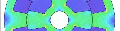
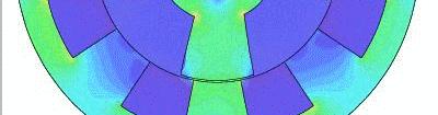
47 1D Axial Topology Rotational Motor By wrapping the linear motor into a circular shape, the linear motion becomes that of a rotation about a central axis. Motion is then described by angular velocity with an effective flux density that depends on angular displacement, r. The magnetic flux density, B( r ) applied depends on the magnet magnetization, geometry, and shape of the rotor/stator system. For permanent magnets, the flux density is viewed from the windings as a periodic function of angular displacement. If the rotor design is produced such that there are no gaps between magnet segments, then one may use the following relation to accurately describe the magnetic flux density relation Rotor North and South PM poles Stator Where B max is the maximum effective flux density produced by the magnets from the winding N m is the number of magnets (segments) n is the integer function of the magnet magnetization, geometry, shape, thickness, separation, and so on.
48 1D Axial Topology Rotational Motor Example Consider the three different magnetic flux density values given Where B max = 0.9 T and N m = 4. max m We can plot B( r ) using the following statements
49 1D Axial Topology Rotational Motor Example Consider the three different magnetic flux density values given Where B max = 0.9 T and N m = 4. max m We can plot B( r ) using the following statements
50 1D Axial Topology Rotational Motor Example Consider the three different magnetic flux density values given Where B max = 0.9 T and N m = 4. max m We can plot B( r ) using the following statements
51
52 Rotary PM DC Motor The electric circuit equation for torque can be derived as where l eq is the effective length, which includes the winding filament length and the lever arm, and N is the number of turns in the coil One can also derived dthe expression for magnetic energy, where A eq is the effective area that takes into account the number of turns, magnetic field no uniformity, etc. Applying One obtains:


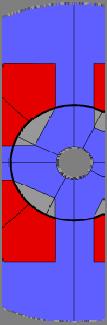
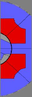
53 Hard Drive Actuator Consider an axial topology PM hard drive actuator assembled with two permanent magnet segments in an array Rotation of the motor is achieved by applying voltage across the current loop. The polarity voltage applied sets the current and therefore the direction of the motor The relative change in magnetization of the two motor segments also contributes to the direction of the rotation In hard drive actuators, a mechanical limiter restricts the angular displacement to Typical hard drives operate with displacement limiters of Applying Kirchhoff s Voltage law to the problem
54 Rotational Hard Disk Motor Example The equation of the circuit must be further limited by use of two (left and right) filaments Likewise, Newton s 2 nd law of motion results in Consider two practical cases when two magnetic strips are magnetized to ensure For these cases, we will let k = 1 and a =10 and 100 for a maximum magnetic flux density of 0.7 Tesla
55 Rotational Hard Disk Motor Example For the case where The electromagnetic torque can then be described as where L and R are the left and right angular displacements respectively. We will solve for the system using the following limiting factors Torque is then expressed as One can further match the system by applying a nonideal Hook s law (for spring forces) to the system
56 Rotational Hard Disk Motor Example For this example, let us use the following parameters
57 Rotational Hard Disk Motor Example Case Number 1:
58 Rotational Hard Disk Motor Example Case Number 2:
59 Rotational Hard Disk Motor Example Case Number 2:
60 Rotational Hard Disk Motor Example Case Number 2:
61 Rotational Hard Disk Motor Example Case Number 2:
62 Rotational Hard Disk Motor Example Case Number 3: Simplified Linear Model
63 Geometrical Variations of Electromechanical lmotion Devices
64
ENGG4420 LECTURE 7. CHAPTER 1 BY RADU MURESAN Page 1. September :29 PM
 CHAPTER 1 BY RADU MURESAN Page 1 ENGG4420 LECTURE 7 September 21 10 2:29 PM MODELS OF ELECTRIC CIRCUITS Electric circuits contain sources of electric voltage and current and other electronic elements such
Introduction. Energy is needed in different forms: Light bulbs and heaters need electrical energy Fans and rolling miles need mechanical energy
 Introduction Energy is needed in different forms: Light bulbs and heaters need electrical energy Fans and rolling miles need mechanical energy What does AC and DC stand for? Electrical machines Motors
Lesson 17: Synchronous Machines
 Lesson 17: Synchronous Machines ET 332b Ac Motors, Generators and Power Systems Lesson 17_et332b.pptx 1 Learning Objectives After this presentation you will be able to: Explain how synchronous machines
Electrical Machines and Energy Systems: Operating Principles (Part 2) SYED A Rizvi
 SYED A Rizvi") Electrical Machines and Energy Systems: Operating Principles (Part 2) SYED A Rizvi AC Machines Operating Principles: Synchronous Motor In synchronous motors, the stator of the motor has a rotating magnetic
Electrical Machines and Energy Systems: Operating Principles (Part 2) SYED A Rizvi AC Machines Operating Principles: Synchronous Motor In synchronous motors, the stator of the motor has a rotating magnetic
School of Mechanical Engineering Purdue University. ME375 ElectroMechanical - 1
 Electro-Mechanical Systems DC Motors Principles of Operation Modeling (Derivation of fg Governing Equations (EOM)) Block Diagram Representations Using Block Diagrams to Represent Equations in s - Domain
Texas A & M University Department of Mechanical Engineering MEEN 364 Dynamic Systems and Controls Dr. Alexander G. Parlos
 Texas A & M University Department of Mechanical Engineering MEEN 364 Dynamic Systems and Controls Dr. Alexander G. Parlos Lecture 6: Modeling of Electromechanical Systems Principles of Motor Operation
Mathematical Modelling of Permanent Magnet Synchronous Motor with Rotor Frame of Reference
 Mathematical Modelling of Permanent Magnet Synchronous Motor with Rotor Frame of Reference Mukesh C Chauhan 1, Hitesh R Khunt 2 1 P.G Student (Electrical),2 Electrical Department, AITS, rajkot 1 mcchauhan1@aits.edu.in
ROEVER COLLEGE OF ENGINEERING & TECHNOLOGY ELAMBALUR, PERAMBALUR DEPARTMENT OF ELECTRICAL AND ELECTRONICS ENGINEERING ELECTRICAL MACHINES I
 ROEVER COLLEGE OF ENGINEERING & TECHNOLOGY ELAMBALUR, PERAMBALUR-621220 DEPARTMENT OF ELECTRICAL AND ELECTRONICS ENGINEERING ELECTRICAL MACHINES I Unit I Introduction 1. What are the three basic types
Model of a DC Generator Driving a DC Motor (which propels a car)
") Model of a DC Generator Driving a DC Motor (which propels a car) John Hung 5 July 2011 The dc is connected to the dc as illustrated in Fig. 1. Both machines are of permanent magnet type, so their respective
Model of a DC Generator Driving a DC Motor (which propels a car) John Hung 5 July 2011 The dc is connected to the dc as illustrated in Fig. 1. Both machines are of permanent magnet type, so their respective
Synchronous Machines
 Synchronous Machines Synchronous generators or alternators are used to convert mechanical power derived from steam, gas, or hydraulic-turbine to ac electric power Synchronous generators are the primary
An Introduction to Electrical Machines. P. Di Barba, University of Pavia, Italy
 An Introduction to Electrical Machines P. Di Barba, University of Pavia, Italy Academic year 0-0 Contents Transformer. An overview of the device. Principle of operation of a single-phase transformer 3.
Mathematical Modeling and Dynamic Simulation of DC Motors using MATLAB/Simulink Environment
 Mathematical Modeling and Dynamic Simulation of DC Motors using MATLAB/Simulink Environment K. Kalaiselvi 1, K.Abinaya 2, P. Ramesh Babu 3 1,2 Under Graduate Scholar, Department of EEE, Saranathan College
Chapter 4. Synchronous Generators. Basic Topology
 Basic Topology Chapter 4 ynchronous Generators In stator, a three-phase winding similar to the one described in chapter 4. ince the main voltage is induced in this winding, it is also called armature winding.
Prince Sattam bin Abdulaziz University College of Engineering. Electrical Engineering Department EE 3360 Electrical Machines (II)
") Chapter # 4 Three-Phase Induction Machines 1- Introduction (General Principles) Generally, conversion of electrical power into mechanical power takes place in the rotating part of an electric motor. In
Chapter # 4 Three-Phase Induction Machines 1- Introduction (General Principles) Generally, conversion of electrical power into mechanical power takes place in the rotating part of an electric motor. In
Applied Electronics and Electrical Machines
 School of Electrical and Computer Engineering Applied Electronics and Electrical Machines (ELEC 365) Fall 2015 DC Machines 1 DC Machines Key educational goals: Develop the basic principle of operation
Note that a current-carrying solenoid produces a dipole field similar to that of a bar magnet. The field is uniform within the coil.
 An electrical current produces a magnetic field that is directed around it. Conventional current is the flow of positive charge. Hence, it is directed from the positive terminal of the power supply, through
Stepping Motors. Chapter 11 L E L F L D
 Chapter 11 Stepping Motors In the synchronous motor, the combination of sinusoidally distributed windings and sinusoidally time varying current produces a smoothly rotating magnetic field. We can eliminate
Equal Pitch and Unequal Pitch:
 Equal Pitch and Unequal Pitch: Equal-Pitch Multiple-Stack Stepper: For each rotor stack, there is a toothed stator segment around it, whose pitch angle is identical to that of the rotor (θs = θr). A stator
Analytical Model for Sizing the Magnets of Permanent Magnet Synchronous Machines
 Journal of Electrical Engineering 3 (2015) 134-141 doi: 10.17265/2328-2223/2015.03.004 D DAVID PUBLISHING Analytical Model for Sizing Magnets of Permanent Magnet Synchronous Machines George Todorov and
Control of Wind Turbine Generators. James Cale Guest Lecturer EE 566, Fall Semester 2014 Colorado State University
 Control of Wind Turbine Generators James Cale Guest Lecturer EE 566, Fall Semester 2014 Colorado State University Review from Day 1 Review Last time, we started with basic concepts from physics such as
ELECTRICALMACHINES-I QUESTUION BANK
 ELECTRICALMACHINES-I QUESTUION BANK UNIT-I INTRODUCTION OF MAGNETIC MATERIAL PART A 1. What are the three basic rotating Electric machines? 2. Name the three materials used in machine manufacture. 3. What
Definition Application of electrical machines Electromagnetism: review Analogies between electric and magnetic circuits Faraday s Law Electromagnetic
 Definition Application of electrical machines Electromagnetism: review Analogies between electric and magnetic circuits Faraday s Law Electromagnetic Force Motor action Generator action Types and parts
Massachusetts Institute of Technology Department of Electrical Engineering and Computer Science Electric Machines
 Massachusetts Institute of Technology Department of Electrical Engineering and Computer Science 6.685 Electric Machines Problem Set 10 Issued November 11, 2013 Due November 20, 2013 Problem 1: Permanent
Electric Machines I Three Phase Induction Motor. Dr. Firas Obeidat
 Electric Machines I Three Phase Induction Motor Dr. Firas Obeidat 1 Table of contents 1 General Principles 2 Construction 3 Production of Rotating Field 4 Why Does the Rotor Rotate 5 The Slip and Rotor
Finite Element Analysis of Hybrid Excitation Axial Flux Machine for Electric Cars
 223 Finite Element Analysis of Hybrid Excitation Axial Flux Machine for Electric Cars Pelizari, A. ademir.pelizari@usp.br- University of Sao Paulo Chabu, I.E. ichabu@pea.usp.br - University of Sao Paulo
MATHEMATICAL MODELING OF OPEN LOOP PMDC MOTOR USING MATLAB/SIMULINK
 MATHEMATICAL MODELING OF OPEN LOOP PMDC MOTOR USING MATLAB/SIMULINK 1 Mr.Dhaval K.Patel 1 Assistant Professor, Dept. of Electrical Engineering. Gidc Degree Engineering College Abrama, Navsari. ABSTRACT:
E11 Lecture 13: Motors. Professor Lape Fall 2010
 E11 Lecture 13: Motors Professor Lape Fall 2010 Overview How do electric motors work? Electric motor types and general principles of operation How well does your motor perform? Torque and power output
CHAPTER 8 DC MACHINERY FUNDAMENTALS
 CHAPTER 8 DC MACHINERY FUNDAMENTALS Summary: 1. A Simple Rotating Loop between Curved Pole Faces - The Voltage Induced in a Rotating Loop - Getting DC voltage out of the Rotating Loop - The Induced Torque
Electrical Machines and Energy Systems: Operating Principles (Part 1) SYED A Rizvi
 SYED A Rizvi") Electrical Machines and Energy Systems: Operating Principles (Part 1) SYED A Rizvi AC Machines Operating Principles: Rotating Magnetic Field The key to the functioning of AC machines is the rotating magnetic
Electrical Machines and Energy Systems: Operating Principles (Part 1) SYED A Rizvi AC Machines Operating Principles: Rotating Magnetic Field The key to the functioning of AC machines is the rotating magnetic
(a) Torsional spring-mass system. (b) Spring element.
 Torsional spring-mass system. (b) Spring element.") m v s T s v a (a) T a (b) T a FIGURE 2.1 (a) Torsional spring-mass system. (b) Spring element. by ky Wall friction, b Mass M k y M y r(t) Force r(t) (a) (b) FIGURE 2.2 (a) Spring-mass-damper system. (b)
m v s T s v a (a) T a (b) T a FIGURE 2.1 (a) Torsional spring-mass system. (b) Spring element. by ky Wall friction, b Mass M k y M y r(t) Force r(t) (a) (b) FIGURE 2.2 (a) Spring-mass-damper system. (b)
Mechatronics Engineering. Li Wen
 Mechatronics Engineering Li Wen Bio-inspired robot-dc motor drive Unstable system Mirko Kovac,EPFL Modeling and simulation of the control system Problems 1. Why we establish mathematical model of the control
2002 Prentice Hall, Inc. Gene F. Franklin, J. David Powell, Abbas Emami-Naeini Feedback Control of Dynamic Systems, 4e
 u Figure 2.1 Cruise-control model x Friction force bx m x u Figure 2.2 Free-body diagram for cruise control S P 278 Figure 2.3 Automobile suspension y m 2 k s b v car x m 1 k w Road surface r Inertial
Flux: Examples of Devices
 Flux: Examples of Devices xxx Philippe Wendling philippe.wendling@magsoft-flux.com Create, Design, Engineer! www.magsoft-flux.com www.cedrat.com Solenoid 2 1 The Domain Axisymmetry Open Boundary 3 Mesh
CHAPTER 5 SIMULATION AND TEST SETUP FOR FAULT ANALYSIS
 47 CHAPTER 5 SIMULATION AND TEST SETUP FOR FAULT ANALYSIS 5.1 INTRODUCTION This chapter describes the simulation model and experimental set up used for the fault analysis. For the simulation set up, the
ENHANCEMENT MAXIMUM POWER POINT TRACKING OF PV SYSTEMS USING DIFFERENT ALGORITHMS
 Journal of Al Azhar University Engineering Sector Vol. 13, No. 49, October, 2018, 1290-1299 ENHANCEMENT MAXIMUM POWER POINT TRACKING OF PV SYSTEMS USING DIFFERENT ALGORITHMS Yasmin Gharib 1, Wagdy R. Anis
Chapter 6: Efficiency and Heating. 9/18/2003 Electromechanical Dynamics 1
 Chapter 6: Efficiency and Heating 9/18/2003 Electromechanical Dynamics 1 Losses As a machine transforms energy from one form to another there is always a certain power loss the loss is expressed as heat,
Revised October 6, EEL 3211 ( 2008, H. Zmuda) 7. DC Machines 1
 7. DC Machines 1") DC Machines Revised October 6, 2008 EEL 3211 ( 2008, H. Zmuda) 7. DC Machines 1 DC Machines: DC Motors are rapidly losing popularity. Until recent advances in power electronics DC motors excelled in terms
DC Machines Revised October 6, 2008 EEL 3211 ( 2008, H. Zmuda) 7. DC Machines 1 DC Machines: DC Motors are rapidly losing popularity. Until recent advances in power electronics DC motors excelled in terms
FEEDBACK CONTROL SYSTEMS
 FEEDBAC CONTROL SYSTEMS. Control System Design. Open and Closed-Loop Control Systems 3. Why Closed-Loop Control? 4. Case Study --- Speed Control of a DC Motor 5. Steady-State Errors in Unity Feedback Control
PROBLEMS - chapter 3 *
 OpenStax-CNX module: m28362 1 PROBLEMS - chapter 3 * NGUYEN Phuc This work is produced by OpenStax-CNX and licensed under the Creative Commons Attribution License 3.0 PROBLEMS This lecture note is based
UJET VOL. 2, NO. 2, DEC Page 8
 UMUDIKE JOURNAL OF ENGINEERING AND TECHNOLOGY (UJET) VOL. 2, NO. 2, DEC 2016 PAGE 8-15 FINITE ELEMENT ANALYSIS OF A 7.5KW ASYNCHRONOUS MOTOR UNDER INTERMITTENT LOADING. Abunike, E. C. and Okoro, O. I.
1439. Numerical simulation of the magnetic field and electromagnetic vibration analysis of the AC permanent-magnet synchronous motor
 1439. Numerical simulation of the magnetic field and electromagnetic vibration analysis of the AC permanent-magnet synchronous motor Bai-zhou Li 1, Yu Wang 2, Qi-chang Zhang 3 1, 2, 3 School of Mechanical
LESSON 20 ALTERNATOR OPERATION OF SYNCHRONOUS MACHINES
 ET 332b Ac Motors, Generators and Power Systems LESSON 20 ALTERNATOR OPERATION OF SYNCHRONOUS MACHINES 1 LEARNING OBJECTIVES After this presentation you will be able to: Interpret alternator phasor diagrams
Electromagnetics and Electric Machines Stefan Holst, CD-adapco
 Electromagnetics and Electric Machines Stefan Holst, CD-adapco Overview Electric machines intro Designing electric machines with SPEED Links to STAR-CCM+ for thermal modeling Electromagnetics in STAR-CCM+
Revision Guide for Chapter 15
 Revision Guide for Chapter 15 Contents tudent s Checklist Revision otes Transformer... 4 Electromagnetic induction... 4 Generator... 5 Electric motor... 6 Magnetic field... 8 Magnetic flux... 9 Force on
Dynamics of the synchronous machine
 ELEC0047 - Power system dynamics, control and stability Dynamics of the synchronous machine Thierry Van Cutsem t.vancutsem@ulg.ac.be www.montefiore.ulg.ac.be/~vct October 2018 1 / 38 Time constants and
MATLAB SIMULINK Based DQ Modeling and Dynamic Characteristics of Three Phase Self Excited Induction Generator
 628 Progress In Electromagnetics Research Symposium 2006, Cambridge, USA, March 26-29 MATLAB SIMULINK Based DQ Modeling and Dynamic Characteristics of Three Phase Self Excited Induction Generator A. Kishore,
DESIGN OF ELECTRICAL APPARATUS SOLVED PROBLEMS
 DESIGN OF ELECTRICAL APPARATUS SOLVED PROBLEMS 1. A 350 KW, 500V, 450rpm, 6-pole, dc generator is built with an armature diameter of 0.87m and core length of 0.32m. The lap wound armature has 660 conductors.
EE155/255 Green Electronics
 EE155/255 Green Electronics Electric Motors 10/16/17 Prof. William Dally Computer Systems Laboratory Stanford University Course Logistics Solar day is Monday 10/23 HW 3 is due today HW 4 out, due next
EE 742 Chapter 3: Power System in the Steady State. Y. Baghzouz
 EE 742 Chapter 3: Power System in the Steady State Y. Baghzouz Transmission Line Model Distributed Parameter Model: Terminal Voltage/Current Relations: Characteristic impedance: Propagation constant: π
Generators for wind power conversion
 Generators for wind power conversion B. G. Fernandes Department of Electrical Engineering Indian Institute of Technology, Bombay Email : bgf@ee.iitb.ac.in Outline of The Talk Introduction Constant speed
EE155/255 Green Electronics
 EE155/255 Green Electronics Electric Motors 10/19/16 Prof. William Dally Computer Systems Laboratory Stanford University This week is flipped Course Logistics Discussion on 10/17, Motors on 10/19, Isolated
Mathematical Modeling and Dynamic Simulation of a Class of Drive Systems with Permanent Magnet Synchronous Motors
 Applied and Computational Mechanics 3 (2009) 331 338 Mathematical Modeling and Dynamic Simulation of a Class of Drive Systems with Permanent Magnet Synchronous Motors M. Mikhov a, a Faculty of Automatics,
DC Motor Position: System Modeling
 1 of 7 01/03/2014 22:07 Tips Effects TIPS ABOUT BASICS INDEX NEXT INTRODUCTION CRUISE CONTROL MOTOR SPEED MOTOR POSITION SUSPENSION INVERTED PENDULUM SYSTEM MODELING ANALYSIS DC Motor Position: System
Nonlinear dynamic simulation model of switched reluctance linear machine
 Procedia Earth and Planetary Science 1 (2009) 1320 1324 Procedia Earth and Planetary Science www.elsevier.com/locate/procedia The 6 th International Conference on Mining Science & Technology Nonlinear
4 Finite Element Analysis of a three-phase PM synchronous machine
 Assignment 4 1-1 4 Finite Element Analysis of a three-phase PM synchronous machine The goal of the third assignment is to extend your understanding on electromagnetic analysis in FEM. This assignment is
International Journal of Advance Engineering and Research Development SIMULATION OF FIELD ORIENTED CONTROL OF PERMANENT MAGNET SYNCHRONOUS MOTOR
 Scientific Journal of Impact Factor(SJIF): 3.134 e-issn(o): 2348-4470 p-issn(p): 2348-6406 International Journal of Advance Engineering and Research Development Volume 2,Issue 4, April -2015 SIMULATION
EDEXCEL NATIONALS UNIT 5 - ELECTRICAL AND ELECTRONIC PRINCIPLES. ASSIGNMENT No. 3 - ELECTRO MAGNETIC INDUCTION
 EDEXCEL NATIONALS UNIT 5 - ELECTRICAL AND ELECTRONIC PRINCIPLES ASSIGNMENT No. 3 - ELECTRO MAGNETIC INDUCTION NAME: I agree to the assessment as contained in this assignment. I confirm that the work submitted
EDEXCEL NATIONAL CERTIFICATE/DIPLOMA UNIT 5 - ELECTRICAL AND ELECTRONIC PRINCIPLES NQF LEVEL 3. OUTCOME 3 - MAGNETISM and INDUCTION
 EDEXCEL NATIONAL CERTIFICATE/DIPLOMA UNIT 5 - ELECTRICAL AND ELECTRONIC PRINCIPLES NQF LEVEL 3 OUTCOME 3 - MAGNETISM and INDUCTION 3 Understand the principles and properties of magnetism Magnetic field:
Step Motor Modeling. Step Motor Modeling K. Craig 1
 Step Motor Modeling Step Motor Modeling K. Craig 1 Stepper Motor Models Under steady operation at low speeds, we usually do not need to differentiate between VR motors and PM motors (a hybrid motor is
PARAMETER SENSITIVITY ANALYSIS OF AN INDUCTION MOTOR
 HUNGARIAN JOURNAL OF INDUSTRIAL CHEMISTRY VESZPRÉM Vol. 39(1) pp. 157-161 (2011) PARAMETER SENSITIVITY ANALYSIS OF AN INDUCTION MOTOR P. HATOS, A. FODOR, A. MAGYAR University of Pannonia, Department of
Sensorless Control for High-Speed BLDC Motors With Low Inductance and Nonideal Back EMF
 Sensorless Control for High-Speed BLDC Motors With Low Inductance and Nonideal Back EMF P.Suganya Assistant Professor, Department of EEE, Bharathiyar Institute of Engineering for Women Salem (DT). Abstract
Mechatronics Modeling and Analysis of Dynamic Systems Case-Study Exercise
 Mechatronics Modeling and Analysis of Dynamic Systems Case-Study Exercise Goal: This exercise is designed to take a real-world problem and apply the modeling and analysis concepts discussed in class. As
Revision Guide for Chapter 15
 Revision Guide for Chapter 15 Contents Revision Checklist Revision otes Transformer...4 Electromagnetic induction...4 Lenz's law...5 Generator...6 Electric motor...7 Magnetic field...9 Magnetic flux...
DESIGN AND ANALYSIS OF AXIAL-FLUX CORELESS PERMANENT MAGNET DISK GENERATOR
 DESIGN AND ANALYSIS OF AXIAL-FLUX CORELESS PERMANENT MAGNET DISK GENERATOR Łukasz DR ZIKOWSKI Włodzimierz KOCZARA Institute of Control and Industrial Electronics Warsaw University of Technology, Warsaw,
Automatic Control Systems. -Lecture Note 15-
 -Lecture Note 15- Modeling of Physical Systems 5 1/52 AC Motors AC Motors Classification i) Induction Motor (Asynchronous Motor) ii) Synchronous Motor 2/52 Advantages of AC Motors i) Cost-effective ii)
MODELING AND HIGH-PERFORMANCE CONTROL OF ELECTRIC MACHINES
 MODELING AND HIGH-PERFORMANCE CONTROL OF ELECTRIC MACHINES JOHN CHIASSON IEEE PRESS ü t SERIES ON POWER ENGINEERING IEEE Press Series on Power Engineering Mohamed E. El-Hawary, Series Editor The Institute
Doubly salient reluctance machine or, as it is also called, switched reluctance machine. [Pyrhönen et al 2008]
![Doubly salient reluctance machine or, as it is also called, switched reluctance machine. [Pyrhönen et al 2008]](/thumbs/86/93665357.jpg "Doubly salient reluctance machine or, as it is also called, switched reluctance machine. [Pyrhönen et al 2008]") Doubly salient reluctance machine or, as it is also called, switched reluctance machine [Pyrhönen et al 2008] Pros and contras of a switched reluctance machine Advantages Simple robust rotor with a small
Doubly salient reluctance machine or, as it is also called, switched reluctance machine [Pyrhönen et al 2008] Pros and contras of a switched reluctance machine Advantages Simple robust rotor with a small
DcMotor_ Model Help File
 Name of Model: DcMotor_021708 Author: Vladimir L. Chervyakov Date: 2002-10-26 Executable file name DcMotor_021708.vtm Version number: 1.0 Description This model represents a Nonlinear model of a permanent
DEVELOPMENT OF DIRECT TORQUE CONTROL MODELWITH USING SVI FOR THREE PHASE INDUCTION MOTOR
 DEVELOPMENT OF DIRECT TORQUE CONTROL MODELWITH USING SVI FOR THREE PHASE INDUCTION MOTOR MUKESH KUMAR ARYA * Electrical Engg. Department, Madhav Institute of Technology & Science, Gwalior, Gwalior, 474005,
6.013 Lecture 12: Magnetic Forces and Devices
 6.013 Lecture 12: Magnetic Forces and Devices A. Overview Magnetic forces are central to a wide array of actuators and sensors. These forces can be calculated using either energy methods or the Lorentz
NEPTUNE -code: KAUVG11ONC Prerequisites:... Knowledge description:
 Subject name: Electrical Machines Credits: 9 Requirement : Course director: Dr. Vajda István Position: Assessment and verification procedures: NEPTUNE -code: KAUVG11ONC Prerequisites:... Number of hours:
Introduction to Synchronous. Machines. Kevin Gaughan
 Introduction to Synchronous Machines Kevin Gaughan The Synchronous Machine An AC machine (generator or motor) with a stator winding (usually 3 phase) generating a rotating magnetic field and a rotor carrying
You know for EE 303 that electrical speed for a generator equals the mechanical speed times the number of poles, per eq. (1).
.") Stability 1 1. Introduction We now begin Chapter 14.1 in your text. Our previous work in this course has focused on analysis of currents during faulted conditions in order to design protective systems
Stability 1 1. Introduction We now begin Chapter 14.1 in your text. Our previous work in this course has focused on analysis of currents during faulted conditions in order to design protective systems
Mechatronic System Case Study: Rotary Inverted Pendulum Dynamic System Investigation
 Mechatronic System Case Study: Rotary Inverted Pendulum Dynamic System Investigation Dr. Kevin Craig Greenheck Chair in Engineering Design & Professor of Mechanical Engineering Marquette University K.
JRE SCHOOL OF Engineering
 JRE SCHOOL OF Engineering Class Test-1 Examinations September 2014 Subject Name Electromechanical Energy Conversion-II Subject Code EEE -501 Roll No. of Student Max Marks 30 Marks Max Duration 1 hour Date
Dynamic Modeling of Surface Mounted Permanent Synchronous Motor for Servo motor application
 797 Dynamic Modeling of Surface Mounted Permanent Synchronous Motor for Servo motor application Ritu Tak 1, Sudhir Y Kumar 2, B.S.Rajpurohit 3 1,2 Electrical Engineering, Mody University of Science & Technology,
Synergetic Control for Electromechanical Systems
 Synergetic Control for Electromechanical Systems Anatoly A. Kolesnikov, Roger Dougal, Guennady E. Veselov, Andrey N. Popov, Alexander A. Kolesnikov Taganrog State University of Radio-Engineering Automatic
Design and Characteristic Analysis of LSM for High Speed Train System using Magnetic Equivalent Circuit
 IJR International Journal of Railway Vol. 3, No. 1 / March 2010, pp. 14-18 The Korean Society for Railway Design and Characteristic Analysis of LSM for High Speed Train System using Magnetic Equivalent
Keywords: Electric Machines, Rotating Machinery, Stator faults, Fault tolerant control, Field Weakening, Anisotropy, Dual rotor, 3D modeling
 Analysis of Electromagnetic Behavior of Permanent Magnetized Electrical Machines in Fault Modes M. U. Hassan 1, R. Nilssen 1, A. Røkke 2 1. Department of Electrical Power Engineering, Norwegian University
Design of the Forced Water Cooling System for a Claw Pole Transverse Flux Permanent Magnet Synchronous Motor
 Design of the Forced Water Cooling System for a Claw Pole Transverse Flux Permanent Magnet Synchronous Motor Ahmad Darabi 1, Ali Sarreshtehdari 2, and Hamed Tahanian 1 1 Faculty of Electrical and Robotic
Overview of motors and motion control
 Overview of motors and motion control. Elements of a motion-control system Power upply High-level controller ow-level controller Driver Motor. Types of motors discussed here; Brushed, PM DC Motors Cheap,
Generalized Theory of Electrical Machines- A Review
 Generalized Theory of Electrical Machines- A Review Dr. Sandip Mehta Department of Electrical and Electronics Engineering, JIET Group of Institutions, Jodhpur Abstract:-This paper provides an overview
University of Jordan Faculty of Engineering & Technology Electric Power Engineering Department
 University of Jordan Faculty of Engineering & Technology Electric Power Engineering Department EE471: Electrical Machines-II Tutorial # 2: 3-ph Induction Motor/Generator Question #1 A 100 hp, 60-Hz, three-phase
6) Motors and Encoders
 Motors and Encoders") 6) Motors and Encoders Electric motors are by far the most common component to supply mechanical input to a linear motion system. Stepper motors and servo motors are the popular choices in linear motion
6) Motors and Encoders Electric motors are by far the most common component to supply mechanical input to a linear motion system. Stepper motors and servo motors are the popular choices in linear motion
3 d Calculate the product of the motor constant and the pole flux KΦ in this operating point. 2 e Calculate the torque.
 Exam Electrical Machines and Drives (ET4117) 11 November 011 from 14.00 to 17.00. This exam consists of 5 problems on 4 pages. Page 5 can be used to answer problem 4 question b. The number before a question
Synchronous Machines
 Synchronous Machines Synchronous Machines n 1 Φ f n 1 Φ f I f I f I f damper (run-up) winding Stator: similar to induction (asynchronous) machine ( 3 phase windings that forms a rotational circular magnetic
Electric Machines I DC Machines - DC Generators. Dr. Firas Obeidat
 Electric Machines I DC Machines DC Generators Dr. Firas Obeidat 1 Table of contents 1 Construction of Simple Loop Generator 2 Working of Simple Loop Generator 3 Types of DC Generators 4 The Terminal Characteristic
Modeling and Analysis of Dynamic Systems
 Modeling and Analysis of Dynamic Systems by Dr. Guillaume Ducard Fall 2016 Institute for Dynamic Systems and Control ETH Zurich, Switzerland 1/22 Outline 1 Lecture 5: Hydraulic Systems Pelton Turbine:
DC motors. 1. Parallel (shunt) excited DC motor
 excited DC motor") DC motors 1. Parallel (shunt) excited DC motor A shunt excited DC motor s terminal voltage is 500 V. The armature resistance is 0,5 Ω, field resistance is 250 Ω. On a certain load it takes 20 A current
DC motors 1. Parallel (shunt) excited DC motor A shunt excited DC motor s terminal voltage is 500 V. The armature resistance is 0,5 Ω, field resistance is 250 Ω. On a certain load it takes 20 A current
Chapter 7. Chapter 7. Electric Circuits Fundamentals - Floyd. Copyright 2007 Prentice-Hall
 Chapter 7 Magnetic Quantities Magnetic fields are described by drawing flux lines that represent the magnetic field. Where lines are close together, the flux density is higher. Where lines are further
UNIT I INTRODUCTION Part A- Two marks questions
 ROEVER COLLEGE OF ENGINEERING & TECHNOLOGY ELAMBALUR, PERAMBALUR-621220 DEPARTMENT OF ELECTRICAL AND ELECTRONICS ENGINEERING DESIGN OF ELECTRICAL MACHINES UNIT I INTRODUCTION 1. Define specific magnetic
ELECTRIC MACHINE TORQUE PRODUCTION 101
 ELECTRIC MACHINE TORQUE PRODUCTION 101 Best Electric Machine, 014 INTRODUCTION: The following discussion will show that the symmetrical (or true dual-ported) transformer electric machine as only provided
Power System Stability and Control. Dr. B. Kalyan Kumar, Department of Electrical Engineering, Indian Institute of Technology Madras, Chennai, India
 Power System Stability and Control Dr. B. Kalyan Kumar, Department of Electrical Engineering, Indian Institute of Technology Madras, Chennai, India Contents Chapter 1 Introduction to Power System Stability
Solved Problems. Electric Circuits & Components. 1-1 Write the KVL equation for the circuit shown.
 Solved Problems Electric Circuits & Components 1-1 Write the KVL equation for the circuit shown. 1-2 Write the KCL equation for the principal node shown. 1-2A In the DC circuit given in Fig. 1, find (i)
Introduction to Control (034040) lecture no. 2
 lecture no. 2") Introduction to Control (034040) lecture no. 2 Leonid Mirkin Faculty of Mechanical Engineering Technion IIT Setup: Abstract control problem to begin with y P(s) u where P is a plant u is a control signal
Introduction to Control (034040) lecture no. 2 Leonid Mirkin Faculty of Mechanical Engineering Technion IIT Setup: Abstract control problem to begin with y P(s) u where P is a plant u is a control signal
Electromagnetic Energy Conversion Exam 98-Elec-A6 Spring 2002
 Front Page Electromagnetic Energy Conversion Exam 98-Elec-A6 Spring 2002 Notes: Attempt question 1 and FOUR (4) other questions (FVE (5) questions in all). Unless you indicate otherwise, the first five
Electromagnetic Induction and Faraday s Law
 Electromagnetic Induction and Faraday s Law Induced EMF Almost 200 years ago, Faraday looked for evidence that a magnetic field would induce an electric current with this apparatus: He found no evidence
Generators. What its all about
 Generators What its all about How do we make a generator? Synchronous Operation Rotor Magnetic Field Stator Magnetic Field Forces and Magnetic Fields Force Between Fields Motoring Generators & motors are
EE 451 Power System Stability
 EE 451 Power System Stability Power system operates in synchronous mode Power system is subjected to a wide range of disturbances (small and large) - Loads and generation changes - Network changes - Faults
CHAPTER 2 CAPACITANCE REQUIREMENTS OF SIX-PHASE SELF-EXCITED INDUCTION GENERATORS
 9 CHAPTER 2 CAPACITANCE REQUIREMENTS OF SIX-PHASE SELF-EXCITED INDUCTION GENERATORS 2.. INTRODUCTION Rapidly depleting rate of conventional energy sources, has led the scientists to explore the possibility