Mechatronics Engineering. Li Wen
|
|
|
- Chester Long
- 6 years ago
- Views:
Transcription


1 Mechatronics Engineering Li Wen

2 Bio-inspired robot-dc motor drive Unstable system Mirko Kovac,EPFL
3 Modeling and simulation of the control system
4 Problems 1. Why we establish mathematical model of the control system? 2. Modeling methods and procedures? 3. How to create a mathematical model of the DC servo motor? 4. The simulation tool of the control system?

5 Contents 1 Significance of control system simulation analysis 2 Modeling methods and procedures 3 DC motor modeling examples 5 4 Analysis and correction for linear motion unit closed-loop simulation Introduction to MATLAB /SIMULINK
6 Contents 1 Significance of control system simulation analysis 2 Modeling methods and procedures 3 DC motor modeling examples 5 4 Analysis and correction for linear motion unit closed-loop simulation Introduction to MATLAB /SIMULINK
7 Establish the significance of the mathematical model By the specific physical problems, from a qualitative understanding of engineering problems to rise to the precise quantitative understanding of the key. Research and to analyze a mechanical control system, not only to qualitatively understand the working principle and characteristics of the system, but also quantitatively describe the system dynamic performance.
8 Basic concepts of mathematical models Mathematical description of the dynamic characteristics of the system: Because during the transition process, the system variable you want to change over time, thus describing the system appears not only in mathematical model of dynamic characteristics of the variable itself, but also contain all order derivatives of these variables, so the system of dynamic equations are differential equations, it is the most basic form representing mathematical model of the system.

9 Bio-inspired soft robot _ slow response
10 Control system modeling approach First, analysis, starting from the physical or chemical laws, establishing mathematical model and experimental verification Two is an experimental method, by adding a certain forms of input signals to the system or component, evaluating output response for system or component, building mathematical models. This lesson uses analysis
11 Principle of establishing mathematical models Inexact: Theoretically none can be absolutely accurate mathematical expressions to describe a system because, in theory, any system is nonlinear, time and distribution parameters change, the random factors are present, the more complex the system, the situation is more complicated. Simplification: Ignore secondary factors, seize the main problem for modeling, quantitative analysis.

12 Mathematical model is divided into: Time Domain Model Complex domain model Frequency domain model Time domain model: Mathematical Model Types Advantages: it is describes the control system in the time domain, and has the advantage of an intuitive, accurate, all of the responses and can provide the system time information. Disadvantages: complex; hard to find system of structure parameters on performance of control system of general rules, cannot find improvement program is not easy on the system analysis and design.
13 Mathematical Model Types Complex domain models: It includes the transfer function and structure of the system. It demonstrates its characteristic of the system and of the input signal;it not only characterize the dynamic performance of the system, but can also affect the structure or the study of changes in system parameters on system performance Frequency domain model: Describes the frequency characteristics of the system, with a clear physical meaning, experimental methods are available to determine.
14 Mathematical Model Types Relationship between the three commonly used mathematical models Linear Systems Transfer function Rumsfeld Transform Differential Equations Fourier Transform Frequency Characteristics
15 Modeling steps 1. A linear system of equations: 1 determine the input and output of the system 2 The system is divided into several areas, from the input start signal is transmitted in the order, according to the laws of physics followed each variable (Newton's law, Kirchhoff's current and voltage law), etc., lists various aspects of linearization original equation; 2. For the establishment of differential equations, Laplace transform one by one, eliminating the intermediate variables, get the system transfer function model

16 Biomimetic robot-dc drive Self-stable system Mirko Kovac,EPFL

17 Biomimetic robot-dc drive Self-stable system with steering Mirko Kovac,EPFL
18 Contents 1 Significance of control system simulation analysis 2 Modeling methods and procedures 3 DC motor modeling examples 5 4 Analysis and correction for linear motion unit closed-loop simulation Introduction to MATLAB /SIMULINK
19 DC modeling analysis Solution: armature controlled DC motor is essentially the work of the input electrical energy into mechanical energy, which is the Input of the armature voltage U a (t) generated armature current I a (t) in the armature circuit, and then by the current I a (t) and the excitation flux generated by the interaction of electromagnetic torque M m (t), to drag the load movement. Therefore, the equation of motion of the DC motor by the following three components. Armature circuit voltage balance equation Electromagnetic torque equation Turn the motor shaft from the balance equation 19
20 DC modeling analysis (1) According to Kirchhoff's voltage law, the armature winding voltage balance equation u i R L di E dt a a a a a a (1) Where, L a and R a were inductance (Henry) and the resistance of the armature windings (Ohm)
21 DC modeling analysis (2) When the rotation of the DC motor armature, the armature windings produce anti potential, it is generally proportional to the motor speed, i.e., d m Ea Ke dt (2) Where, E a is the back EMF (V), K e is a scaling factor (V.rad / s)
22 DC modeling analysis (3) the interaction between the armature current and the magnetic field to produce an electromagnetic torque. General electromagnetic torque is proportional to the armature current, namely: M m K i m a (3) Where M m is the electromagnetic torque (Nm), I a is the armature current (A), K m for the moment coefficient (Nm / A)
23 DC modeling analysis (4) for driving the electromagnetic torque to overcome the friction and load torque, assuming only consider the viscous friction is proportional to the speed, the DC motor torque balance equation 2 d m d m M m J m B () 2 m M c t dt dt The formula: J m The total moment of inertia of the motor shaft (Including the moment of inertia of the rotor and the load) 牛米.. 秒 2 m B m M () c t The angular displacement of the motor shaft (rad); As a viscous friction coefficient of the motor shaft The role of the applied load on the motor shaft torque 牛. 米 / 弧度 / 秒
24 DC modeling analysis m To find the angular velocity and load control model of the motor armature voltage U, namely the transfer function. We assume zero initial conditions in these kinds of Laplace Transform, respectively U s L I s s R I s E s a a a a a a E s K s a e m m m a M s K I s M s ( J S B ) s M s m m m m c
25 DC modeling analysis Erasing the armature current ia, and then take the armature voltage Ua is input, the angular velocity of the motor output shaft, i.e., m m s s. U s Whereby the DC motor can be controlled in the model, i.e., the transfer function is: a s 2 m Km (s) U s L J s ( L B J R ) s R B K K a a m a m m a a m e m
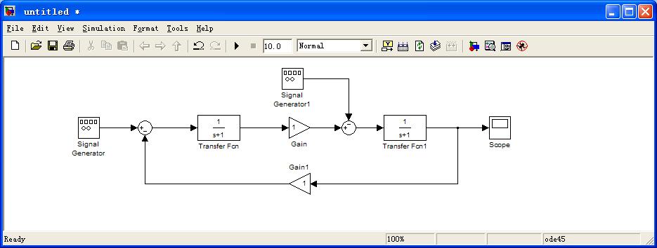
26 DC modeling analysis Created in MATLAB using the Simulink simulation model DC servo motor Structure

27 Li Wen et al, Beihang University

28 DC modeling analysis
29 Open Simulink

30 Modeling Overview of Linear Motion Units Linear motion units has flexibility and mechanical friction, etc., so it is virtually impossible to establish a precise mathematical model. We usually use approximate model, assuming driver and transmission is ideal rigid, and there is no elastic deformation
31 New Simulink model
32 The system block diagram of the various modules and drag it to the model file Pull in


33 Modeling of linear motion unit control system (2) Linear motion unit components Coupling Ball screw Reducer DC motor
34 The system block diagram of the various modules and drag it to the model file
35 The system block diagram of all the modules file and drag it to the model and adjust the layout and orientation
36 Connection
37 Variable and label
38 DC modeling analysis Substituting parameters L a,r a,j m,b m,k m,k e L a = 0.001Hery;R a = 1.2oum;J m = 1e-5 kg.m 2 ;B m = 5e-4;K m = 0.08N.m/A;K e = 0.08V.S/rad; Input signal: Amplitude of Input voltage U a is 1V, the frequency of square wave is 1Hz Amplitude of the interference torque Mf 0.01Nm, frequency of sinusoidal signal 1Hz Simulink block diagram to obtain arguments:
39 matlab m files for variable assignment
40 Generate input and load (or disturbance torque) signal generator Click on Run Amplitude of Input voltage is Ua 1V, the frequency of square wave is 1Hz Amplitude of the interference torque Mf 0.01Nm, frequency sinusoidal signal of 1Hz For example: motor Slip ring friction Produce
41 DC modeling analysis Judging from the simulation curve, the response curve is a cycle curve, is in response to a step input and Input of the linear superposition of the load cycle, from the curve to see the system is still stable, which can be from the poles and zeros of the transfer function are located to the left half plane verify get.
42 DC modeling analysis Necessary and sufficient conditions for stability of the system is necessary All the roots of the characteristic equation must be negative real part, that is all the roots in the complex plane of the left half-plane Root system characteristics 0.08 G(s) = e-08 s^ e-05 s Continuous-time transfer function i i 2 s 2 m Cm U s L J s ( L B J R ) s R B C C a a m a m m a a m e m
43 DC modeling analysis J m Impact on system performance Overshoot Jm=10-5 Jm=10-4 Jm=10-3 In three Jm, the system is stable, but smaller overshoot Jm more powerful; Jm greater the longer the rise time of the system.
44 DC modeling analysis B m impact on performance(b m bigger (output / input) becomes smaller, shorter adjustment time) Bm =1X10⁻⁴ Bm =5X10⁻⁴ Bm =2X10⁻³ The greater the damping coefficient, the smaller the value of the unit step response (speed / voltage value becomes smaller), the rise time becomes longer, but the time to reach steady state becomes shorter.
45 DC modeling analysis Load impact on performance Mc = 1Nm Mc = 2Nm Mc = 3Nm Load increase reduce the system response (moving speed), larger changes in the steady-state error of the system (open-loop steady-state error is large), the adjustment time becomes longer, the rise time becomes long.
46 Contents 1 Significance of control system simulation analysis 2 Modeling methods and procedures 3 DC motor modeling examples 5 4 Analysis and correction for linear motion unit closed-loop simulation Introduction to MATLAB /SIMULINK
 as the output, establish a mathematic model for the linear motion unit speed control system.")
47 Modeling Overview of linear motion units Model building Specify the slider velocity (unit: mm/s) as the input, and the slider actual speed (mm/s) as the output, establish a mathematic model for the linear motion unit speed control system.
48 Modeling of linear motion unit control system (1) Linear motion unit system components and parameters Rated voltage 24V Back-EMF constant (Ke) v*s/rad Reduction ratio (i) 29:1 Amplifier (Ka) 2.4 Motor resistor (Ra) 21.6 欧 Torque constant (Km) N*m/A Motor inductance (La) Screw lead (p) 1.97mH 2mm Rotor moment of inertia (Jx) Equivalent damping (Bm) kg. m Screw diameter (d) 11.5mm Speed gain (Ka) v*s/rad Screw Length (L) Workbench mass (m) 540mm 0.315kg Equivalent moment of inertia of the motor shaft d ( ) 2 p d l m ( ) J e -7 kg m 2 m J x i 2
49 Modeling of linear motion unit control system 1. The relationship between the motor and the screw speed The actual relationship between the rotational speed of the motor shaft and the screw speed: ( i is reduction ratio and the value is 29) m o t t m Motor shaft speed t i t Actural speed of screw o
50 Modeling of linear motion unit control system 2. Modeling of DC servo motor
51 Modeling of linear motion unit control system 2. Modeling of DC servo motor Potential balance equation of armature windings: Relations between the counter-electromotive force and speed The relationship between the armature current and the armature torque is: Torque balance equation is:

52 Modeling of linear motion unit control system 3. Angular velocity feedback To constitute the load shaft speed control system, there must be speed feedback of load shaft, the error voltage can be obtained by velocity error: n t t n u t k t t a a n m is the input shaft speed of motor; k a u a k a is the speed feedback gain t t m
53 Modeling of linear motion unit control system Laplace transform of the above formula : m t i t o s i s M K i ( N m) m m a a u k () t L di R i dt a e m a a a d m(t) M m(t) J m Bm m (t) Mc(t) dt m o m m a M s K I s U s L I s s R I s k s a a a a a e (s) M s J s s B s M m m m m m c u t k t t a a n m u s k s s a a n m This equation describes the relationship between the input control voltage U and the rotational angular velocity of the drive shaft.
54 Modeling of linear motion unit control system Specify the slider velocity (unit: mm/s) as the input, and the slider actual speed (mm/s) as the output, establish a mathematic model for the linear motion unit speed control system. The above notation is expressed as the angular velocity, as the screw lead P is 2mm, we can Build relationships between line speed and angular velocity. o s V o P 2 Vo 2 o s P o t is input speed Vo is slider speed
55 Modeling of linear motion unit control system Build the system model in Simulink:
56 After determining the mathematical model of the system, you can use several different methods to analyze the dynamic performance and steady-state performance of the control system. Method: Simulation analysis of control systems Time domain analysis Frequency domain analysis.
57 Simulation analysis of control systems Dynamic performance and steady-state performance

58 Simulation analysis of control systems Input step signal (amplitude is 1) to analyze the time-domain response From the results, we can get that rise time, peak time and settling time are relatively small, although there is a certain system overshoot, but eventually stabilized, but there is an error between the input and output. Therefore, system stability and accuracy are not very well.

59 Simulation analysis of control systems Analyze the system frequency response, draw bode plot

60 Simulation analysis of control systems Analyze the system frequency response, draw Nyquist plot Conclusion: The system gain margin is infinite, phase margin is 71.8, system stability is very good.
61 Impacts on system when change parameters Impact on the performance of the screw lead 2mm 6mm 8mm In the open-loop control, when lead increases, changes in steady-state error is large and the system response increases, rise time get lower.
62 Impacts on system when change parameters Impact on the performance of the screw lead 2mm 6mm 8mm In the open-loop control, changes in lead will not change the dynamic characteristic.
63 Impacts on system when change parameters Impact on the performance of the reduction ratio In the open-loop control, when the reduction ratio increases, system response time decreases
64 Impacts on system when change parameters Impact on the performance of the reduction ratio In the open-loop control, changes in reduction ratio will not change the dynamic characteristic.


65 Impacts on system when change parameters Changing the system structure parameters, and analyze its impact on system performance

66 Impacts on system when change parameters Bode plot

67 Open Simulink
68 Contents 1 Significance of control system simulation analysis 2 Modeling methods and procedures 3 DC motor modeling examples 5 4 Analysis and correction for linear motion unit closed-loop simulation Introduction to MATLAB /SIMULINK
69 biorobotics_fast response X0.1 Active control Rob Wood lab, Harvard University


70 New Simulink model


71 According to the system block diagram, and drag various modules to the model file Drag
72 According to the system block diagram, and drag various modules to the model file
73
74 Connection
75 Brought variables and mark
76 DC modeling analysis Brought parameters: L a,r a,j m,b m,k m,k e L a = 0.001H; R a = 1.2Ω; J m = 1e-5 kg.m 2 ;B m = 5e-4;K m = 0.08N.m/A; K e = 0.08V.S/rad; Input signal is: Square wave: Input voltage U a is 1V,frequency is 1Hz; Sin signal: Disturbance torque M f is 0.01N.m, frequency is 1Hz; Simulink block diagram:

77 Variable assignment in matlab m file

78 Generate input and load (or disturbance torque) signal using generator Run Input voltage U a : 1V, frequency 1Hz, of square wave. Disturbance torque M f is 0.01N.m, frequency 1Hz, of sin signal.
79 DC modeling analysis Judging from the simulation curve, the response curve is a cycle curve, which is a linear superposition response to a step input and periodic load input. From the curve to see the system is still stable, which can be verified from the transfer function poles and zeros are in the left half plane.

80
DC Motor Position: System Modeling
 1 of 7 01/03/2014 22:07 Tips Effects TIPS ABOUT BASICS INDEX NEXT INTRODUCTION CRUISE CONTROL MOTOR SPEED MOTOR POSITION SUSPENSION INVERTED PENDULUM SYSTEM MODELING ANALYSIS DC Motor Position: System
Lesson 17: Synchronous Machines
 Lesson 17: Synchronous Machines ET 332b Ac Motors, Generators and Power Systems Lesson 17_et332b.pptx 1 Learning Objectives After this presentation you will be able to: Explain how synchronous machines
Example: Modeling DC Motor Position Physical Setup System Equations Design Requirements MATLAB Representation and Open-Loop Response
 Page 1 of 5 Example: Modeling DC Motor Position Physical Setup System Equations Design Requirements MATLAB Representation and Open-Loop Response Physical Setup A common actuator in control systems is the
DcMotor_ Model Help File
 Name of Model: DcMotor_021708 Author: Vladimir L. Chervyakov Date: 2002-10-26 Executable file name DcMotor_021708.vtm Version number: 1.0 Description This model represents a Nonlinear model of a permanent
Example: DC Motor Speed Modeling
 Page 1 of 5 Example: DC Motor Speed Modeling Physical setup and system equations Design requirements MATLAB representation and open-loop response Physical setup and system equations A common actuator in
Quanser NI-ELVIS Trainer (QNET) Series: QNET Experiment #02: DC Motor Position Control. DC Motor Control Trainer (DCMCT) Student Manual
 Series: QNET Experiment #02: DC Motor Position Control. DC Motor Control Trainer (DCMCT) Student Manual") Quanser NI-ELVIS Trainer (QNET) Series: QNET Experiment #02: DC Motor Position Control DC Motor Control Trainer (DCMCT) Student Manual Table of Contents 1 Laboratory Objectives1 2 References1 3 DCMCT Plant
Quanser NI-ELVIS Trainer (QNET) Series: QNET Experiment #02: DC Motor Position Control DC Motor Control Trainer (DCMCT) Student Manual Table of Contents 1 Laboratory Objectives1 2 References1 3 DCMCT Plant
The basic principle to be used in mechanical systems to derive a mathematical model is Newton s law,
 Chapter. DYNAMIC MODELING Understanding the nature of the process to be controlled is a central issue for a control engineer. Thus the engineer must construct a model of the process with whatever information
R10 JNTUWORLD B 1 M 1 K 2 M 2. f(t) Figure 1
 Figure 1") Code No: R06 R0 SET - II B. Tech II Semester Regular Examinations April/May 03 CONTROL SYSTEMS (Com. to EEE, ECE, EIE, ECC, AE) Time: 3 hours Max. Marks: 75 Answer any FIVE Questions All Questions carry
Code No: R06 R0 SET - II B. Tech II Semester Regular Examinations April/May 03 CONTROL SYSTEMS (Com. to EEE, ECE, EIE, ECC, AE) Time: 3 hours Max. Marks: 75 Answer any FIVE Questions All Questions carry
FEEDBACK CONTROL SYSTEMS
 FEEDBAC CONTROL SYSTEMS. Control System Design. Open and Closed-Loop Control Systems 3. Why Closed-Loop Control? 4. Case Study --- Speed Control of a DC Motor 5. Steady-State Errors in Unity Feedback Control
Index. Index. More information. in this web service Cambridge University Press
 A-type elements, 4 7, 18, 31, 168, 198, 202, 219, 220, 222, 225 A-type variables. See Across variable ac current, 172, 251 ac induction motor, 251 Acceleration rotational, 30 translational, 16 Accumulator,
Manufacturing Equipment Control
 QUESTION 1 An electric drive spindle has the following parameters: J m = 2 1 3 kg m 2, R a = 8 Ω, K t =.5 N m/a, K v =.5 V/(rad/s), K a = 2, J s = 4 1 2 kg m 2, and K s =.3. Ignore electrical dynamics
EDEXCEL NATIONALS UNIT 5 - ELECTRICAL AND ELECTRONIC PRINCIPLES. ASSIGNMENT No. 3 - ELECTRO MAGNETIC INDUCTION
 EDEXCEL NATIONALS UNIT 5 - ELECTRICAL AND ELECTRONIC PRINCIPLES ASSIGNMENT No. 3 - ELECTRO MAGNETIC INDUCTION NAME: I agree to the assessment as contained in this assignment. I confirm that the work submitted
Mechatronics Modeling and Analysis of Dynamic Systems Case-Study Exercise
 Mechatronics Modeling and Analysis of Dynamic Systems Case-Study Exercise Goal: This exercise is designed to take a real-world problem and apply the modeling and analysis concepts discussed in class. As
Mechatronic System Case Study: Rotary Inverted Pendulum Dynamic System Investigation
 Mechatronic System Case Study: Rotary Inverted Pendulum Dynamic System Investigation Dr. Kevin Craig Greenheck Chair in Engineering Design & Professor of Mechanical Engineering Marquette University K.
JRE SCHOOL OF Engineering
 JRE SCHOOL OF Engineering Class Test-1 Examinations September 2014 Subject Name Electromechanical Energy Conversion-II Subject Code EEE -501 Roll No. of Student Max Marks 30 Marks Max Duration 1 hour Date
School of Mechanical Engineering Purdue University. ME375 ElectroMechanical - 1
 Electro-Mechanical Systems DC Motors Principles of Operation Modeling (Derivation of fg Governing Equations (EOM)) Block Diagram Representations Using Block Diagrams to Represent Equations in s - Domain
ME 3210 Mechatronics II Laboratory Lab 4: DC Motor Characteristics
 ME 3210 Mechatronics II Laboratory Lab 4: DC Motor Characteristics Introduction Often, due to budget constraints or convenience, engineers must use whatever tools are available to create new or improved
INC 341 Feedback Control Systems: Lecture 3 Transfer Function of Dynamic Systems II
 INC 341 Feedback Control Systems: Lecture 3 Transfer Function of Dynamic Systems II Asst. Prof. Dr.-Ing. Sudchai Boonto Department of Control Systems and Instrumentation Engineering King Mongkut s University
ECEN 420 LINEAR CONTROL SYSTEMS. Lecture 6 Mathematical Representation of Physical Systems II 1/67
 1/67 ECEN 420 LINEAR CONTROL SYSTEMS Lecture 6 Mathematical Representation of Physical Systems II State Variable Models for Dynamic Systems u 1 u 2 u ṙ. Internal Variables x 1, x 2 x n y 1 y 2. y m Figure
Positioning Servo Design Example
 Positioning Servo Design Example 1 Goal. The goal in this design example is to design a control system that will be used in a pick-and-place robot to move the link of a robot between two positions. Usually
International Journal of Advance Research in Computer Science and Management Studies
 Volume 2, Issue 9, September 2014 ISSN: 2321 7782 (Online) International Journal of Advance Research in Computer Science and Management Studies Research Article / Survey Paper / Case Study Available online
Lezione 9 30 March. Scribes: Arianna Marangon, Matteo Vitturi, Riccardo Prota
 Control Laboratory: a.a. 2015/2016 Lezione 9 30 March Instructor: Luca Schenato Scribes: Arianna Marangon, Matteo Vitturi, Riccardo Prota What is left to do is how to design the low pass pole τ L for the
ENGG4420 LECTURE 7. CHAPTER 1 BY RADU MURESAN Page 1. September :29 PM
 CHAPTER 1 BY RADU MURESAN Page 1 ENGG4420 LECTURE 7 September 21 10 2:29 PM MODELS OF ELECTRIC CIRCUITS Electric circuits contain sources of electric voltage and current and other electronic elements such
Introduction to Control (034040) lecture no. 2
 lecture no. 2") Introduction to Control (034040) lecture no. 2 Leonid Mirkin Faculty of Mechanical Engineering Technion IIT Setup: Abstract control problem to begin with y P(s) u where P is a plant u is a control signal
Introduction to Control (034040) lecture no. 2 Leonid Mirkin Faculty of Mechanical Engineering Technion IIT Setup: Abstract control problem to begin with y P(s) u where P is a plant u is a control signal
Coupled Drive Apparatus Modelling and Simulation
 University of Ljubljana Faculty of Electrical Engineering Victor Centellas Gil Coupled Drive Apparatus Modelling and Simulation Diploma thesis Menthor: prof. dr. Maja Atanasijević-Kunc Ljubljana, 2015
Automatic Control Systems. -Lecture Note 15-
 -Lecture Note 15- Modeling of Physical Systems 5 1/52 AC Motors AC Motors Classification i) Induction Motor (Asynchronous Motor) ii) Synchronous Motor 2/52 Advantages of AC Motors i) Cost-effective ii)
UNIVERSITY OF BOLTON SCHOOL OF ENGINEERING BSC (HONS) MECHATRONICS TOP-UP SEMESTER 1 EXAMINATION 2017/2018 ADVANCED MECHATRONIC SYSTEMS
 MECHATRONICS TOP-UP SEMESTER 1 EXAMINATION 2017/2018 ADVANCED MECHATRONIC SYSTEMS") ENG08 UNIVERSITY OF BOLTON SCHOOL OF ENGINEERING BSC (HONS) MECHATRONICS TOP-UP SEMESTER EXAMINATION 07/08 ADVANCED MECHATRONIC SYSTEMS MODULE NO: MEC600 Date: 7 January 08 Time: 0.00.00 INSTRUCTIONS TO
ENG08 UNIVERSITY OF BOLTON SCHOOL OF ENGINEERING BSC (HONS) MECHATRONICS TOP-UP SEMESTER EXAMINATION 07/08 ADVANCED MECHATRONIC SYSTEMS MODULE NO: MEC600 Date: 7 January 08 Time: 0.00.00 INSTRUCTIONS TO
ECE 5670/6670 Lab 8. Torque Curves of Induction Motors. Objectives
 ECE 5670/6670 Lab 8 Torque Curves of Induction Motors Objectives The objective of the lab is to measure the torque curves of induction motors. Acceleration experiments are used to reconstruct approximately
Appendix A: Exercise Problems on Classical Feedback Control Theory (Chaps. 1 and 2)
") Appendix A: Exercise Problems on Classical Feedback Control Theory (Chaps. 1 and 2) For all calculations in this book, you can use the MathCad software or any other mathematical software that you are familiar
Appendix A: Exercise Problems on Classical Feedback Control Theory (Chaps. 1 and 2) For all calculations in this book, you can use the MathCad software or any other mathematical software that you are familiar
R a) Compare open loop and closed loop control systems. b) Clearly bring out, from basics, Force-current and Force-Voltage analogies.
 Compare open loop and closed loop control systems. b) Clearly bring out, from basics, Force-current and Force-Voltage analogies.") SET - 1 II B. Tech II Semester Supplementary Examinations Dec 01 1. a) Compare open loop and closed loop control systems. b) Clearly bring out, from basics, Force-current and Force-Voltage analogies..
SET - 1 II B. Tech II Semester Supplementary Examinations Dec 01 1. a) Compare open loop and closed loop control systems. b) Clearly bring out, from basics, Force-current and Force-Voltage analogies..
SRV02-Series Rotary Experiment # 1. Position Control. Student Handout
 SRV02-Series Rotary Experiment # 1 Position Control Student Handout SRV02-Series Rotary Experiment # 1 Position Control Student Handout 1. Objectives The objective in this experiment is to introduce the
Overview of motors and motion control
 Overview of motors and motion control. Elements of a motion-control system Power upply High-level controller ow-level controller Driver Motor. Types of motors discussed here; Brushed, PM DC Motors Cheap,
Lab 3: Model based Position Control of a Cart
 I. Objective Lab 3: Model based Position Control of a Cart The goal of this lab is to help understand the methodology to design a controller using the given plant dynamics. Specifically, we would do position
Stepping Motors. Chapter 11 L E L F L D
 Chapter 11 Stepping Motors In the synchronous motor, the combination of sinusoidally distributed windings and sinusoidally time varying current produces a smoothly rotating magnetic field. We can eliminate
Electrical Machine & Automatic Control (EEE-409) (ME-II Yr) UNIT-3 Content: Signals u(t) = 1 when t 0 = 0 when t <0
 (ME-II Yr) UNIT-3 Content: Signals u(t) = 1 when t 0 = 0 when t <0") Electrical Machine & Automatic Control (EEE-409) (ME-II Yr) UNIT-3 Content: Modeling of Mechanical : linear mechanical elements, force-voltage and force current analogy, and electrical analog of simple
Electrical Machine & Automatic Control (EEE-409) (ME-II Yr) UNIT-3 Content: Modeling of Mechanical : linear mechanical elements, force-voltage and force current analogy, and electrical analog of simple
Rotary Motion Servo Plant: SRV02. Rotary Experiment #01: Modeling. SRV02 Modeling using QuaRC. Student Manual
 Rotary Motion Servo Plant: SRV02 Rotary Experiment #01: Modeling SRV02 Modeling using QuaRC Student Manual SRV02 Modeling Laboratory Student Manual Table of Contents 1. INTRODUCTION...1 2. PREREQUISITES...1
Open Access Permanent Magnet Synchronous Motor Vector Control Based on Weighted Integral Gain of Sliding Mode Variable Structure
 Send Orders for Reprints to reprints@benthamscienceae The Open Automation and Control Systems Journal, 5, 7, 33-33 33 Open Access Permanent Magnet Synchronous Motor Vector Control Based on Weighted Integral
EE 410/510: Electromechanical Systems Chapter 4
 EE 410/510: Electromechanical Systems Chapter 4 Chapter 4. Direct Current Electric Machines and Motion Devices Permanent Magnet DC Electric Machines Radial Topology Simulation and Experimental Studies
International Journal of Advance Engineering and Research Development SIMULATION OF FIELD ORIENTED CONTROL OF PERMANENT MAGNET SYNCHRONOUS MOTOR
 Scientific Journal of Impact Factor(SJIF): 3.134 e-issn(o): 2348-4470 p-issn(p): 2348-6406 International Journal of Advance Engineering and Research Development Volume 2,Issue 4, April -2015 SIMULATION
Laboratory Exercise 1 DC servo
 Laboratory Exercise DC servo Per-Olof Källén ø 0,8 POWER SAT. OVL.RESET POS.RESET Moment Reference ø 0,5 ø 0,5 ø 0,5 ø 0,65 ø 0,65 Int ø 0,8 ø 0,8 Σ k Js + d ø 0,8 s ø 0 8 Off Off ø 0,8 Ext. Int. + x0,
Revision Guide for Chapter 15
 Revision Guide for Chapter 15 Contents tudent s Checklist Revision otes Transformer... 4 Electromagnetic induction... 4 Generator... 5 Electric motor... 6 Magnetic field... 8 Magnetic flux... 9 Force on
Introduction to Synchronous. Machines. Kevin Gaughan
 Introduction to Synchronous Machines Kevin Gaughan The Synchronous Machine An AC machine (generator or motor) with a stator winding (usually 3 phase) generating a rotating magnetic field and a rotor carrying
Rotational Systems, Gears, and DC Servo Motors
 Rotational Systems Rotational Systems, Gears, and DC Servo Motors Rotational systems behave exactly like translational systems, except that The state (angle) is denoted with rather than x (position) Inertia
Modelling and simulation of a measurement robot
 Modellbygge och Simulering, TSRT62 Modelling and simulation of a measurement robot Denna version: 4 oktober 2017 Servo- motor Strömregulator + u + i(t) [A] r (t) [V] u(t) [V] Arm Skruvtransmission Remtransmission
King Saud University
 motor speed (rad/sec) Closed Loop Step Response ing Saud University College of Engineering, Electrical Engineering Department Labwork Manual EE 356 Control and Instrumentation Laboratory (كهر 356 معمل
3 Lab 3: DC Motor Transfer Function Estimation by Explicit Measurement
 3 Lab 3: DC Motor Transfer Function Estimation by Explicit Measurement 3.1 Introduction There are two common methods for determining a plant s transfer function. They are: 1. Measure all the physical parameters
Mathematical Modelling of Permanent Magnet Synchronous Motor with Rotor Frame of Reference
 Mathematical Modelling of Permanent Magnet Synchronous Motor with Rotor Frame of Reference Mukesh C Chauhan 1, Hitesh R Khunt 2 1 P.G Student (Electrical),2 Electrical Department, AITS, rajkot 1 mcchauhan1@aits.edu.in
Mathematical Modeling and Dynamic Simulation of a Class of Drive Systems with Permanent Magnet Synchronous Motors
 Applied and Computational Mechanics 3 (2009) 331 338 Mathematical Modeling and Dynamic Simulation of a Class of Drive Systems with Permanent Magnet Synchronous Motors M. Mikhov a, a Faculty of Automatics,
Laboratory 11 Control Systems Laboratory ECE3557. State Feedback Controller for Position Control of a Flexible Joint
 Laboratory 11 State Feedback Controller for Position Control of a Flexible Joint 11.1 Objective The objective of this laboratory is to design a full state feedback controller for endpoint position control
3 d Calculate the product of the motor constant and the pole flux KΦ in this operating point. 2 e Calculate the torque.
 Exam Electrical Machines and Drives (ET4117) 11 November 011 from 14.00 to 17.00. This exam consists of 5 problems on 4 pages. Page 5 can be used to answer problem 4 question b. The number before a question
Lab 3: Quanser Hardware and Proportional Control
 Lab 3: Quanser Hardware and Proportional Control The worst wheel of the cart makes the most noise. Benjamin Franklin 1 Objectives The goal of this lab is to: 1. familiarize you with Quanser s QuaRC tools
Equal Pitch and Unequal Pitch:
 Equal Pitch and Unequal Pitch: Equal-Pitch Multiple-Stack Stepper: For each rotor stack, there is a toothed stator segment around it, whose pitch angle is identical to that of the rotor (θs = θr). A stator
SCHOOL OF ELECTRICAL, MECHANICAL AND MECHATRONIC SYSTEMS. Transient Stability LECTURE NOTES SPRING SEMESTER, 2008
 SCHOOL OF ELECTRICAL, MECHANICAL AND MECHATRONIC SYSTEMS LECTURE NOTES Transient Stability SPRING SEMESTER, 008 October 7, 008 Transient Stability Transient stability refers to the ability of a synchronous
Mathematical Modeling and Dynamic Simulation of DC Motors using MATLAB/Simulink Environment
 Mathematical Modeling and Dynamic Simulation of DC Motors using MATLAB/Simulink Environment K. Kalaiselvi 1, K.Abinaya 2, P. Ramesh Babu 3 1,2 Under Graduate Scholar, Department of EEE, Saranathan College
Feedback Control Systems
 ME Homework #0 Feedback Control Systems Last Updated November 06 Text problem 67 (Revised Chapter 6 Homework Problems- attached) 65 Chapter 6 Homework Problems 65 Transient Response of a Second Order Model
2.004 Dynamics and Control II Spring 2008
 MIT OpenCourseWare http://ocw.mit.edu 2.004 Dynamics and Control II Spring 2008 For information about citing these materials or our Terms of Use, visit: http://ocw.mit.edu/terms. Massachusetts Institute
Dynamics of the synchronous machine
 ELEC0047 - Power system dynamics, control and stability Dynamics of the synchronous machine Thierry Van Cutsem t.vancutsem@ulg.ac.be www.montefiore.ulg.ac.be/~vct October 2018 1 / 38 Time constants and
Modelling of Ball and Plate System Based on First Principle Model and Optimal Control
 2017 21st International Conference on Process Control (PC) June 6 9, 2017, Štrbské Pleso, Slovakia Modelling of Ball and Plate System Based on First Principle Model and Optimal Control František Dušek,
Dynamic Modeling of Surface Mounted Permanent Synchronous Motor for Servo motor application
 797 Dynamic Modeling of Surface Mounted Permanent Synchronous Motor for Servo motor application Ritu Tak 1, Sudhir Y Kumar 2, B.S.Rajpurohit 3 1,2 Electrical Engineering, Mody University of Science & Technology,
Step Motor Modeling. Step Motor Modeling K. Craig 1
 Step Motor Modeling Step Motor Modeling K. Craig 1 Stepper Motor Models Under steady operation at low speeds, we usually do not need to differentiate between VR motors and PM motors (a hybrid motor is
ME 375 Final Examination Thursday, May 7, 2015 SOLUTION
 ME 375 Final Examination Thursday, May 7, 2015 SOLUTION POBLEM 1 (25%) negligible mass wheels negligible mass wheels v motor no slip ω r r F D O no slip e in Motor% Cart%with%motor%a,ached% The coupled
An Introduction to Electrical Machines. P. Di Barba, University of Pavia, Italy
 An Introduction to Electrical Machines P. Di Barba, University of Pavia, Italy Academic year 0-0 Contents Transformer. An overview of the device. Principle of operation of a single-phase transformer 3.
ADMISSION TEST INDUSTRIAL AUTOMATION ENGINEERING
 UNIVERSITÀ DEGLI STUDI DI PAVIA ADMISSION TEST INDUSTRIAL AUTOMATION ENGINEERING September 26, 2016 The candidates are required to answer the following multiple choice test which includes 30 questions;
Elctromagnetic hammer with impact
 Elctromagnetic hammer with impact There are many technical systems that are based on the principles of construction of an Electromagnetic hammer with impact. The Figure shown 4.42 shows the sketch of such
INDUCTION MOTOR MODEL AND PARAMETERS
 APPENDIX C INDUCTION MOTOR MODEL AND PARAMETERS C.1 Dynamic Model of the Induction Motor in Stationary Reference Frame A three phase induction machine can be represented by an equivalent two phase machine
Basic Electrical Engineering SYLLABUS. Total No. of Lecture Hrs. : 50 Exam Marks : 80
 SYLLABUS Subject Code: /25 No. of Lecture Hrs./ Week : 04 IA Marks : 20 Exam Hours : 03 Total No. of Lecture Hrs. : 50 Exam Marks : 80 Course objectives: Impart a basic knowledge of electrical quantities
System Modeling: Motor position, θ The physical parameters for the dc motor are:
 Dept. of EEE, KUET, Sessional on EE 3202: Expt. # 2 2k15 Batch Experiment No. 02 Name of the experiment: Modeling of Physical systems and study of their closed loop response Objective: (i) (ii) (iii) (iv)
E11 Lecture 13: Motors. Professor Lape Fall 2010
 E11 Lecture 13: Motors Professor Lape Fall 2010 Overview How do electric motors work? Electric motor types and general principles of operation How well does your motor perform? Torque and power output
MODELING AND HIGH-PERFORMANCE CONTROL OF ELECTRIC MACHINES
 MODELING AND HIGH-PERFORMANCE CONTROL OF ELECTRIC MACHINES JOHN CHIASSON IEEE PRESS ü t SERIES ON POWER ENGINEERING IEEE Press Series on Power Engineering Mohamed E. El-Hawary, Series Editor The Institute
Spontaneous Speed Reversals in Stepper Motors
 Spontaneous Speed Reversals in Stepper Motors Marc Bodson University of Utah Electrical & Computer Engineering 50 S Central Campus Dr Rm 3280 Salt Lake City, UT 84112, U.S.A. Jeffrey S. Sato & Stephen
Performance of Feedback Control Systems
 Performance of Feedback Control Systems Design of a PID Controller Transient Response of a Closed Loop System Damping Coefficient, Natural frequency, Settling time and Steady-state Error and Type 0, Type
The Control of an Inverted Pendulum
 The Control of an Inverted Pendulum AAE 364L This experiment is devoted to the inverted pendulum. Clearly, the inverted pendulum will fall without any control. We will design a controller to balance the
Modeling and Simulation of the Nonlinear Computed Torque Control in Simulink/MATLAB for an Industrial Robot
 Copyright 2013 Tech Science Press SL, vol.10, no.2, pp.95-106, 2013 Modeling and Simulation of the Nonlinear Computed Torque Control in Simulink/MATLAB for an Industrial Robot Dǎnuţ Receanu 1 Abstract:
Electromagnetic Induction and Faraday s Law
 Electromagnetic Induction and Faraday s Law Induced EMF Almost 200 years ago, Faraday looked for evidence that a magnetic field would induce an electric current with this apparatus: He found no evidence
ELECTROMAGNETIC OSCILLATIONS AND ALTERNATING CURRENT
 Chapter 31: ELECTROMAGNETIC OSCILLATIONS AND ALTERNATING CURRENT 1 A charged capacitor and an inductor are connected in series At time t = 0 the current is zero, but the capacitor is charged If T is the
Tutorial 1 - Drive fundamentals and DC motor characteristics
 University of New South Wales School of Electrical Engineering & elecommunications ELEC4613 ELECRIC DRIVE SYSEMS utorial 1 - Drive fundamentals and DC motor characteristics 1. In the hoist drive system
Massachusetts Institute of Technology Department of Electrical Engineering and Computer Science Electric Machines
 Massachusetts Institute of Technology Department of Electrical Engineering and Computer Science 6.685 Electric Machines Problem Set 10 Issued November 11, 2013 Due November 20, 2013 Problem 1: Permanent
MATHEMATICAL MODELING OF OPEN LOOP PMDC MOTOR USING MATLAB/SIMULINK
 MATHEMATICAL MODELING OF OPEN LOOP PMDC MOTOR USING MATLAB/SIMULINK 1 Mr.Dhaval K.Patel 1 Assistant Professor, Dept. of Electrical Engineering. Gidc Degree Engineering College Abrama, Navsari. ABSTRACT:
Chapter 4. Synchronous Generators. Basic Topology
 Basic Topology Chapter 4 ynchronous Generators In stator, a three-phase winding similar to the one described in chapter 4. ince the main voltage is induced in this winding, it is also called armature winding.
Induction_P1. 1. [1 mark]
![Induction_P1. 1. [1 mark]](/thumbs/88/115570773.jpg "Induction_P1. 1. [1 mark]") Induction_P1 1. [1 mark] Two identical circular coils are placed one below the other so that their planes are both horizontal. The top coil is connected to a cell and a switch. The switch is closed and
Induction_P1 1. [1 mark] Two identical circular coils are placed one below the other so that their planes are both horizontal. The top coil is connected to a cell and a switch. The switch is closed and
Real-Time Implementation of a LQR-Based Controller for the Stabilization of a Double Inverted Pendulum
 Proceedings of the International MultiConference of Engineers and Computer Scientists 017 Vol I,, March 15-17, 017, Hong Kong Real-Time Implementation of a LQR-Based Controller for the Stabilization of
Bangladesh University of Engineering and Technology. EEE 402: Control System I Laboratory
 Bangladesh University of Engineering and Technology Electrical and Electronic Engineering Department EEE 402: Control System I Laboratory Experiment No. 4 a) Effect of input waveform, loop gain, and system
The control of a gantry
 The control of a gantry AAE 364L In this experiment we will design a controller for a gantry or crane. Without a controller the pendulum of crane will swing for a long time. The idea is to use control
Solved Problems. Electric Circuits & Components. 1-1 Write the KVL equation for the circuit shown.
 Solved Problems Electric Circuits & Components 1-1 Write the KVL equation for the circuit shown. 1-2 Write the KCL equation for the principal node shown. 1-2A In the DC circuit given in Fig. 1, find (i)
Synchronous Machines
 Synchronous Machines Synchronous generators or alternators are used to convert mechanical power derived from steam, gas, or hydraulic-turbine to ac electric power Synchronous generators are the primary
Predictive Cascade Control of DC Motor
 Volume 49, Number, 008 89 Predictive Cascade Control of DC Motor Alexandru MORAR Abstract: The paper deals with the predictive cascade control of an electrical drive intended for positioning applications.
MECH 3140 Final Project
 MECH 3140 Final Project Final presentation will be held December 7-8. The presentation will be the only deliverable for the final project and should be approximately 20-25 minutes with an additional 10
Model of a DC Generator Driving a DC Motor (which propels a car)
") Model of a DC Generator Driving a DC Motor (which propels a car) John Hung 5 July 2011 The dc is connected to the dc as illustrated in Fig. 1. Both machines are of permanent magnet type, so their respective
Model of a DC Generator Driving a DC Motor (which propels a car) John Hung 5 July 2011 The dc is connected to the dc as illustrated in Fig. 1. Both machines are of permanent magnet type, so their respective
LESSON 20 ALTERNATOR OPERATION OF SYNCHRONOUS MACHINES
 ET 332b Ac Motors, Generators and Power Systems LESSON 20 ALTERNATOR OPERATION OF SYNCHRONOUS MACHINES 1 LEARNING OBJECTIVES After this presentation you will be able to: Interpret alternator phasor diagrams
MCE380: Measurements and Instrumentation Lab. Chapter 5: Electromechanical Transducers
 MCE380: Measurements and Instrumentation Lab Chapter 5: Electromechanical Transducers Part I Topics: Transducers and Impedance Magnetic Electromechanical Coupling Reference: Holman, CH 4. Cleveland State
Video 5.1 Vijay Kumar and Ani Hsieh
 Video 5.1 Vijay Kumar and Ani Hsieh Robo3x-1.1 1 The Purpose of Control Input/Stimulus/ Disturbance System or Plant Output/ Response Understand the Black Box Evaluate the Performance Change the Behavior
Lab 6a: Pole Placement for the Inverted Pendulum
 Lab 6a: Pole Placement for the Inverted Pendulum Idiot. Above her head was the only stable place in the cosmos, the only refuge from the damnation of the Panta Rei, and she guessed it was the Pendulum
UNIVERSITY OF WASHINGTON Department of Aeronautics and Astronautics
 UNIVERSITY OF WASHINGTON Department of Aeronautics and Astronautics Modeling and Control of a Flexishaft System March 19, 2003 Christopher Lum Travis Reisner Amanda Stephens Brian Hass AA/EE-448 Controls
Rotary Motion Servo Plant: SRV02. Rotary Experiment #11: 1-DOF Torsion. 1-DOF Torsion Position Control using QuaRC. Student Manual
 Rotary Motion Servo Plant: SRV02 Rotary Experiment #11: 1-DOF Torsion 1-DOF Torsion Position Control using QuaRC Student Manual Table of Contents 1. INTRODUCTION...1 2. PREREQUISITES...1 3. OVERVIEW OF
PID Controller Design for DC Motor
 Contemporary Engineering Sciences, Vol. 11, 2018, no. 99, 4913-4920 HIKARI Ltd, www.m-hikari.com https://doi.org/10.12988/ces.2018.810539 PID Controller Design for DC Motor Juan Pablo Trujillo Lemus Department
Modeling and Simulation Revision III D R. T A R E K A. T U T U N J I P H I L A D E L P H I A U N I V E R S I T Y, J O R D A N
 Modeling and Simulation Revision III D R. T A R E K A. T U T U N J I P H I L A D E L P H I A U N I V E R S I T Y, J O R D A N 0 1 4 Block Diagrams Block diagram models consist of two fundamental objects:
A FORCE BALANCE TECHNIQUE FOR MEASUREMENT OF YOUNG'S MODULUS. 1 Introduction
 A FORCE BALANCE TECHNIQUE FOR MEASUREMENT OF YOUNG'S MODULUS Abhinav A. Kalamdani Dept. of Instrumentation Engineering, R. V. College of Engineering, Bangalore, India. kalamdani@ieee.org Abstract: A new
Modeling and Simulation Revision IV D R. T A R E K A. T U T U N J I P H I L A D E L P H I A U N I V E R S I T Y, J O R D A N
 Modeling and Simulation Revision IV D R. T A R E K A. T U T U N J I P H I L A D E L P H I A U N I V E R S I T Y, J O R D A N 2 0 1 7 Modeling Modeling is the process of representing the behavior of a real
Lab 5a: Pole Placement for the Inverted Pendulum
 Lab 5a: Pole Placement for the Inverted Pendulum November 1, 2011 1 Purpose The objective of this lab is to achieve simultaneous control of both the angular position of the pendulum and horizontal position
IfA Fachpraktikum - Experiment 3.7A : Flexible Shaft A
 Automatic Control Laboratory, ETH Zürich Profs. M. Morari, J. Lygeros Manual prepared by: P. Brunner, F. Ullmann, S. Richter, C. Fischer Revision from: February 16, 2013 IfA Fachpraktikum - Experiment