From now, we ignore the superbar - with variables in per unit. ψ ψ. l ad ad ad ψ. ψ ψ ψ
|
|
|
- Chrystal Glenn
- 6 years ago
- Views:
Transcription
1 From now, we ignore the superbar - with variables in per unit. ψ 0 L0 i0 ψ L + L L L i d l ad ad ad d ψ F Lad LF MR if = ψ D Lad MR LD id ψ q Ll + Laq L aq i q ψ Q Laq LQ iq 41
2 Equivalent Circuits for d- and q-axes e d = -ω r ψ q -R a i d + pψ d = -ω r ψ q -R a i d +L ad d(-i d +i F +i D )/dt -L l di d /dt e F = R F i F + pψ F = R F i F -L ad di d /dt +L F di F /dt +M R di D /dt e D =0= R D i D +pψ D =R D i D -L ad di d /dt +M R di F /dt +L D di D /dt L l +L ad e q = ω r ψ d -R a i q + pψ q =ω r ψ d -R a i q +L aq d(-i q +i Q )/dt -L l di q /dt e Q =0=R Q i Q +pψ Q =R Q i Q -L aq di q /dt + L Q di Q /dt L l +L aq 42
3 Equivalent Circuits for d- and q-axes e d = L ad d(-i d +i F +i D )/dt -L l di d /dt -ω r ψ q -R a i d e F = -L ad di d /dt +L F di F /dt +M R di D /dt +R F i F i D +i F = L ad d(-i d +i F +i D )/dt +(M R - L ad ) d(i D +i F ) /dt +(L F - M R ) di F /dt + R F i F e D =0= -L ad di d /dt +M R di F /dt +L D di D /dt+ R D i D = L ad d(-i d +i F +i D )/dt +(M R - L ad ) d(i D +i F ) +(L D - M R ) di D /dt+ R D i D e q = L aq d(-i q +i Q )/dt -L l di q /dt +ω r ψ d -R a i q e Q =0= -L aq di q /dt + L Q di Q /dt +R Q i Q = L aq d(-i q +i Q )/dt +(L Q -L aq ) di Q /dt +R Q i Q 43
4 Equivalent Circuits with Multiple Damper Windings (e.g. Round-rotor Machines) d axis: L fd L F - M R R fd R F e fd e F L 1d (or L kd1 ) L D - M R R 1d (or R kd1 ) R D M R -L ad 0 ψ fd ψ F (named L fkd1 in some literature to model rotor mutual flux leakage, i.e. the flux linking the rotor s field and damper windings but not stator windings) q axis: L 1q (or L kq1 ) L Q L aq R 1q (or R kq1 ) R Q L 2q (or L kq2 ) L G - L aq R 2q (or R kq2 ) R G L 1d =L D - M R R 1d =R D L 1q =L Q L aq R 1q =R Q L fd =L F - M R R fd =R F e fd =e F L 2q =L G L aq R 2q =R G 44
5 Example: a model with 3 rotor windings in each of d- and q-axis equivalent circuits EPRI Report EL-1424-V2, Determination of Synchronous Machine Stability Study Constants, Volume 2, 1980 The proposed equivalent circuits are expected to contain sufficient details to model all machines Parameters are estimated by frequency response tests 45
6 46
7 Example 3.1 (Kundur s book) A 555 MVA, 24kV, 0.9p.f., 60Hz, 3 phase, 2 pole synchronous generator has the following inductances an resistances associated with the stator and field windings: l aa = cos(2θ) mh l ab = cos(2θ+π/3) mh l af =40.0 cosθ mh L F = mh R a = Ω R F = Ω a. Determine L d and L q in H b. If the stator leakage inductance L l is mH, determine L ad and L aq in H c. Using the machine rated values as the base values for the stator quantities, determine the per unit values of the following in the L ad base reciprocal per unit system (assuming L ad =M F =M R in per unit): L l, L ad, L aq, L d, L q, M F, L F, L fd, R a and R F Solution: a. l aa =L s + L m cos2θ = cos2θ mh l ab = -M s - L m cos(2θ+π/3) = cos(2θ+π/3) mh l af = M F cosθ =40.0 cosθ mh L d = L s + M s + 3L m /2 = = mh L q = L s + M s - 3L m /2 = = mh b. L ad = L d L l = = mh L aq = L q L l = =4.432 mh 47
8 c. 3-phase VA base = 555 MVA E RMS base =24/ 3 = kv e s base (peak) = 2 E RMS base = = kv I RMS base =3-phaseVAbase / (3 E RMS base )= /( )= A i s base (peak) = 2 I RMS base = = A Z s base =e s base /i s base = /( ) = Ω ω base =2π 60 =377 elec. rad/s L s base =Z s base /ω base = / =2.753 mh i F base =L ad /M F i s base =4.5696/ = A e F base =3-phaseVAbase/i Fbase = /2158 = kv Z F base = e F base / i F base = /2158 = Ω L F base = Z F base / ω base = /377 = mh M F base = L S base i S base / i F base = /2158 =241 mh Then per unit values are: L l =0.4129/2.753 =0.15 pu M F =M F /M F base =400/241 =1.66 pu L ad =4.5696/2.753 =1.66 pu L F =576.92/ =1.825 pu L aq =4.432/2.753 =1.61pu L fd = L F -M R =L F -L ad = =0.165 pu L d = L l + L ad = =1.81 pu R a =0.0031/ =0.003 pu L q = L l + L aq = =1.76 pu R F =0.0715/ = pu 48
9 Steady-state Analysis All flux linkages, voltages and currents are constant: pψ 1d =0 R 1d i 1d =0 i 1d =0 pψ 1q =0 R 1q i 1q =0 i 1q =0 (Damper winding currents are all zero due to no change in the magnetic field) ψ d = -( L l +L ad )i d +L ad i fd +L ad i 1d = -L d i d +L ad i fd ψ q = -( L l +L aq )i q +L aq i 1q = -L q i q pψ d =0 e d = -ω r ψ q -R a i d =ω r L q i q -R a i d pψ q =0 e q =ω r ψ d -R a i q =-ω r L d i d +ω r L ad i fd -R a i q pψ fd =0 e fd = R fd i fd ω r =1 and L=X in p.u. e d =X q i q -R a i d e q =-X d i d +X ad i fd -R a i q i fd =(e q + R a i q +X d i d )/X ad Can we have a single equivalent circuit representing both d and q axes circuits under balanced steady-state conditions? 49
10 e a = E m cos(ω s t+α) e b = E m cos(ω s t +α-2π/3) e c = E m cos(ω s t +α+2π/3) θ=ω r t+θ 0 e d = E m cos(α -θ 0 )= E t cos(α -θ 0 ) e q = E m sin(α -θ 0 ) = E t sin(α -θ 0 ) where E t is the per unit RMS value of the armature terminal voltage, which equals the peak value E m in per unit. E t =e d +je q I t=i d +ji q e d =X q i q -R a i d e q =-X d i d +X ad i fd -R a i q E t = X q i q -R a i d +-jx d i d +jx ad i fd -jr a i q = -R a I t +X q i q -jx d i d +jx ad i fd E t = E R a I t jx S I t X S =X q E =j[x ad i fd -(X d -X q )i d ] E q E E I t E t Load E t =E q R a I t jx q I t 50
11 Steady-state equivalent circuit Under no-load or open-circuit conditions, i d =i q =0. E t = E q =jx ad i fd δ i =0 (load angle) E q =j[x ad i fd -(X d -X q )i d ] For round rotor machines or machines with neglected saliency X d =X q =X s (synchronous reactance) E t =E q (R a +jx s )I t E q =X ad i fd 51
12 Computing steady-state values 52
13 Representation of Magnetic Saturation Assumptions for stability studies The leakage fluxes are not significantly affected by saturation of the iron portion, so L l is constant and only L ad and L aq saturate in equivalent circuits L adu L ad L aqu L aq L adu and L aqu denote the unsaturated values The leakage fluxes do not contribute to the iron saturation. Thus, saturation is determined only by the air-gap flux linkage ψ at = ψ 2 2 aa + ψ aa The saturation relationship ψ at ~ i fd or ψ at ~ MMF under loaded conditions is the same as under no-load conditions. This allows the open-circuit characteristic (OCC) to be considered No magnetic coupling between d and q axes, such that their effects of saturation can be modeled individually 53
14 Air-gap flux and voltage ψ = ψ + jψ at ad aq = ψ + Li + jψ + jli d l d q l q = eq + Raiq jed jraid + LlI t = je jr I + L I t a t l t = j[ E + ( R + jx ) I ] = je t a l t at For steady state conditions: e d = -ψ q -R a i d ψ q = - e d -R a i d e q = ψ d - R a i q ψ d = e q + R a i q ψ = E = E + ( R + jx ) I at at t a l t 54

15 Estimating Saturation Factors K sd and K sd L ad =K sd L adu L aq =K sq L aqu Salient pole machines The path for q-axis flux is largely in air, so L aq does not vary significantly with saturation of the iron portion of the path Assume K sq =1.0 for all loading conditions. Round rotor machines There is a magnetic saturation in both axes, but q axis saturation data is usually not available Assume K sq =K sd Thus, we focus on estimating K sd K sd = L ad /L adu =ψ at /ψ at0 = ψ at /(ψ at + ψ I ) = I 0 / I (See Kundur s Example 3.3 on Estimating K sd for different loading conditions) 55
16 Estimating the Saturation Characteristic Modeled by 3 approximate functions Segment I (ψ at <ψ T1 ): ψ I =ψ at0 - ψ at =0 Segment II (ψ T1 <ψ at <ψ T2 ): ψ I = A sss e B sss(ψ aa ψ TT ) Segment III (ψ at >ψ T2 ): ψ I nonlinear linear ψ I =ψ G2 +L ratio (ψ at -ψ T2 )- ψ at Note that segments I and II are not connected since when ψ at =ψ T1, ψ I =A sat 0 (usually small) Assume that segments II and III are connected at ψ at =ψ T2 to solve ψ G2 A sss e B sss(ψ TT ψ TT ) =ψ G2 +L ratio (ψ T2 -ψ T2 )- ψ T2 ψ G2 = ψ T2 +A sss e B sss(ψ TT ψ TT ) linear We need to know A sat, B sat, ψ T1, ψ T2 and L ratio 56
17 57
18 P186 of Anderson s book S(1.0) S(1.2) ψ I = A sss e B sss(ψ aa ψ TT ) ~ S G = Ae G B G ( V 0.8) t 58
19 Example 3.2 in Kundur s Book R 1d >>R fd L fd /R fd >>L 1d /R 1d M R L 1q /R 1q >>L 2q /R 2q 59
20 60
21 39.1 o 1.565pu 61
22 Sub-transient and Transient Analysis Following a disturbance, currents are induced in rotor circuits. Some of these induced rotor currents decay more rapidly than others. Sub-transient parameters: influencing rapidly decaying (cycles) components Transient parameters: influencing the slowly decaying (seconds) components Synchronous parameters: influencing sustained (steady state) components 62
23 Transient and sub-transient parameters R 1d >>R fd L fd /R fd >>L 1d /R 1d d axis circuit L 1q /R 1q >>L 2q /R 2q q axis circuit Considered rotor windings Time constant (open circuit) Time constant (short circuit) T d0 = 8.07(s) T d = Only field Winding L aa +L ff R ff L aa //L l + L ff R ff Add the damper winding Only 1 st damper winding T d = L aa //L ff //L l + L 1d T q = L aa //L l + L 1q T q = R 1d R 1q Add the 2 nd damper winding L T d0 = aa //L ff + L 1d T q0 = L aa +L 1q T q0 = L aa //L 1q + L 2q R 1d R 1q R 2q 0.03(s) 1.00(s) 0.07(s) L aa //L 1q //L l + L 2q R 2q Inductance (Reactance) L d = L l +L ad //L fd L d = L l +L ad //L fd //L 1d L q = L L q = l +L aq //L 1q L l +L aq //L 1q //L 2q 0.30(pu) 0.23(pu) 0.65(pu) 0.25(pu) Based on the parameters of Example
: ψ d (s) = G(s) e fd (s) L d (s) i d (s) ψ q (s) = L q (s) i q (s) L d (1 + st4)(1 + st6) (1 + st )(1 + st ) 1 3 G 0 (1 + st kd ) (1 + st )(1 + st ) 1 3 Since R 1d >>R fd T 2, T 3 <<T")
24 Identifying Terminal Quantities Apply Laplace transform to the incremental forms of flux linkage equations (see Kundur s Chapter 4.1 for details): ψ d (s) = G(s) e fd (s) L d (s) i d (s) ψ q (s) = L q (s) i q (s) L d (1 + st4)(1 + st6) (1 + st )(1 + st ) 1 3 G 0 (1 + st kd ) (1 + st )(1 + st ) 1 3 Since R 1d >>R fd T 2, T 3 <<T 1, T 5,T 6 <<T 4 >> T 1 +T 2 T 1 +T 3, T 4 +T 5 T 4 +T 6 >> >> (1 + st )(1 + st ) (1 + st )(1 + st ) d d 4 6 (1 + st )(1 + st ) (1 + st )(1 + st ) d0 d (Classical Expressions)
25 65
26 Summary of Transient and Sub-transient Parameters (Classical Expressions) d axis circuit q axis circuit OC Time Constant SC Time Constant T d0 = L aa +L ff R ff T d = L aa //L l + L ff R ff T d0 = T q0 = T q0 = L aa //L ff + L L aa +L 1q 1d R R 1q L aa //L 1q + L 2q 1d R 2q T d = T q = T q = L aa //L ff //L l + L L aa //L l + L 1q 1d L R R aa //L 1q //L l + L 2 1q 1d R 2q Inductance (Reactance) L d = L d = L l +L ad //L fd L l +L ad //L fd //L 1d L q = L q = L l +L aq //L 1q L l +L aq //L 1q //L 2q Note: time constants are all in p.u. To be converted to seconds, they have to be multiplied by t base =1/ω base (i.e. 1/377 for 60Hz). 66
27 Synchronous, Transient and Sub-transient Inductances L d ( s) = L d (1 + st d )(1 + (1 + st )(1 + st d ) st ) d 0 d 0 Under steady-state condition: s=0 (t ) L d (0)=L d (d-axis synchronous inductance) During a rapid transient: s TT L = L ( ) = L = L + L L L d d ad fd 1d d d d l T d 0T d 0 Lad Lfd + Lad L1 d + Lfd L1 d (d-axis sub-transient inductance) Without the damper winding :s>>1/t d and 1/T d0 but << 1/T d and 1/T d0 T L = L ( ) = L = L + L L d ad fd d d d l T d 0 Lad + Lfd (d-axis transient inductance) 67
28 X d X q X q X d X q X d T d0 > T d > >T d0 > T d T q0 > T q > >T q0 > T q 68

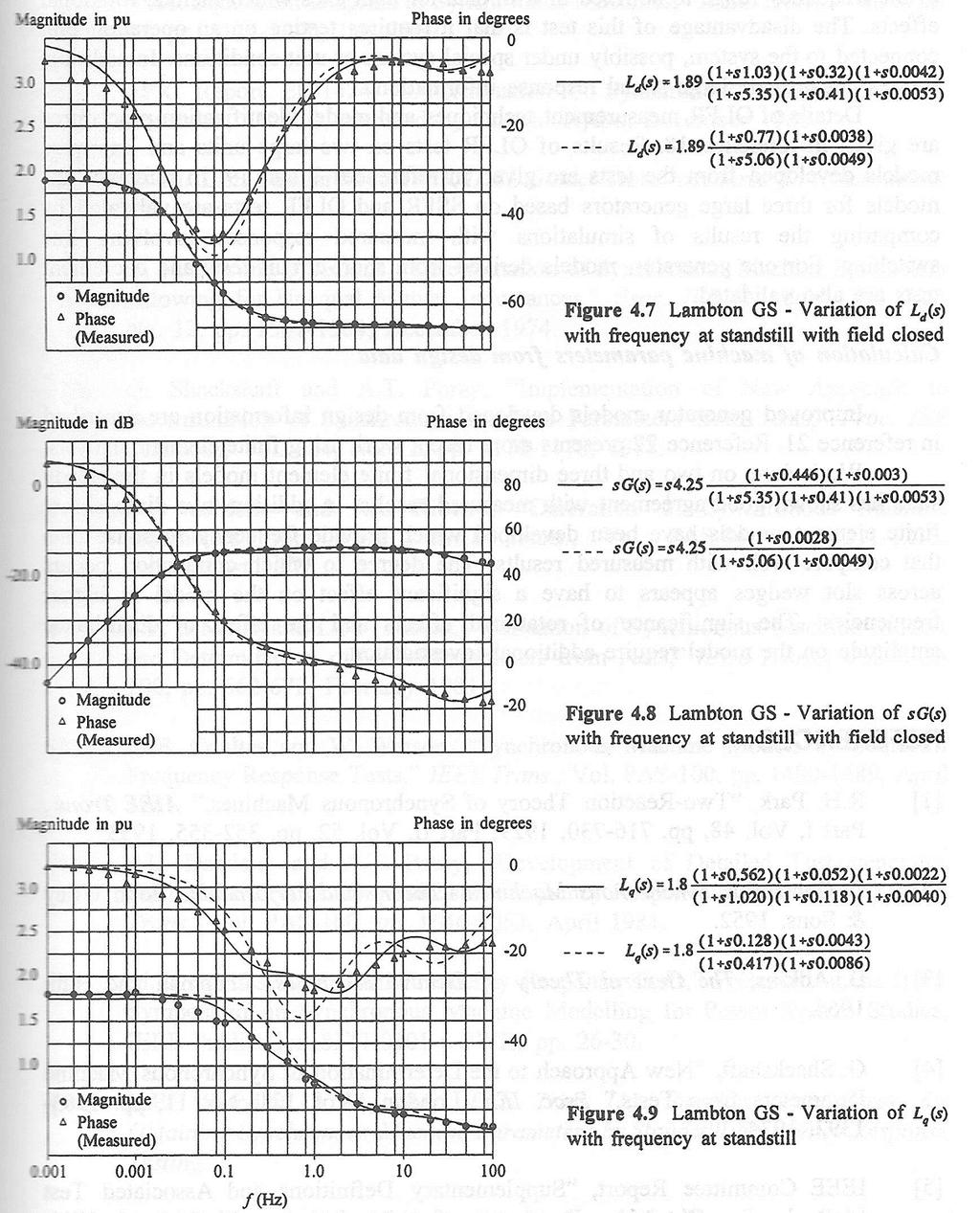
29 Parameter Estimation by Frequency Response Tests ψ d (s) = G(s) e fd (s) L d (s) i d (s) T d0 > T d > >T d0 > T d > T kd 1/T d0 <1/ T d << 1/T d0 <1/T d <1/T kd Bode Plot -20dB/decade 69
30 70
31 Swing Equations J ω m = Ta = Tm T J combined moment of inertia of generator e and turbine, kg m 2 ω m angular velocity of the rotor, mech. rad/s t time, s T a accelerating torque in N.m T m mechanical torque in N.m electromagnetic torque in N.m d dt T e Define per unit inertia constant H = 2 1 Jω 2 VA 0m base (s) (s) J = 2H ω 0 2 VA base m Some references define T M or M=2H, called the mechanical starting time, i.e. the time required for rated torque to accelerate the rotor from standstill to rated speed 71
32 dωm J = T = T T dt 2H dωm VA = T T 2 ω dt 0m a m e base m e d ω m Tm Te 2H = dt ω VA / 0m base ω0m d ω m Tm Te 2H = dt ω 0m T base dωr 2 H = Tm Te (in per unit) dt where ω ωr / p m f ωr ω r (in per unit) = = = ω ω / p ω 0m 0 f 0 Angular position of the rotor in electrical radian with respect to a synchronously rotating reference δ = ω ω t+ δ in rad r t 0 0 dδ = ωr ω0 = ωr in rad/s dt d d δ dω d( ωr) = = in rad/s 2 2 r 2 dt dt dt δ d( ω ) d( ωr) = = in rad/s dt r ω0 dt ω0 dt ω ω 1 ω r r = = ω0 0 dδ dt If adding a damping term proportional to speed deviation: 2 2Hdδ = T 2 m T ω dt 0 2 ω 72 e Hd 2 δ D = T - = - 2 m Te K K d D ωr Tm Te 0 dt ω0 δ dt
33 Block diagram representation of swing equations 2 ω Hd 2 δ D = T - = - 2 m Te K K d D ωr Tm Te 0 dt ω0 d( ωr ) 2H = Tm Te -KD ωr dt ω = r 1 ω 0 dδ dt δ dt 73
34 State-Space Representation of a Synchronous Machine So far, we modeled all critical dynamics about a synchronous machine: State variables (px): stator and rotor voltages, currents or flux linkages swing equations (rotor angle and speed) Time constants: Inertia: 2H Sub-transient and transient time constants, e.g. T d0 and T d0 Other parameters Stator and rotor self- or mutual-inductances and resistances Rotor mechanical torque T m and stator electromagnetic torque T e 74
35 Differential Equations on a Salient-pole Machine Consider 5 windings (d, F, D, q and Q) Voltage equations: e=r i+l di/dt+ω r N I pi = - L -1 (R+ω r N) i +L -1 e Swing equations: Since ψ=l i, here is pψ= - (R+ω r N)L -1 ψ+e τ pω r =T m -T e (where τ=2h/ω 0 ) pδ=ω r - ω 0 =ω r - 1 T e = ψ d i q ψ q i d ψ d = L d i d + km F i F + km D i D, ψ q = L q i q + km Q i Q T e = L d i q i d + km F i q i F + km D i q i D + L q i d i q km Q i d i Q 75
36 d State-space Model i i i i i ω r δ 0 0 i 0 0 d i L R+ ω N r i D Le 0 0 = (T d0, T d0, T q0, T q0 ) iq i Q L i km i km i L i km i d q F q D q q d Q d / 0 0 ω r T τ m τ τ τ τ τ δ d F 1 F D / dt q Q Thus, the state-space model of a synchronous machine: dx/dt=f(x, e d, e q and e fd, T m ) where x=[i d i Fd i 1d i q i 1q ω r δ] T or [ψ d ψ fd ψ 1d ψ q ψ 1q ω r δ] T is the state vector. (See the section 4.12 in Anderson s book). e fd and T m are usually known but e d and e q are related to state variables, so additional equations (on the machine outside, e.g. loading conditions) should be introduced 76
37 Simplified Models [ψ d ψ fd ψ 1d ψ q ψ 1q ω r δ] T Neglect pψ d, pψ q and variations of ω r (i.e. ω r =1 pu) in the voltage equations =ψ q = -L q i q [ψ fd ψ 1d ψ 1q ω r δ] T Inertia τ ~ pω r Transient T d0 ~ pψ fd Sub-transient T d0 ~pψ 1d T q0 ~ pψ 1q [ψ fd ω r δ] T Neglect damper windings, i.e. pψ 1d and pψ 1q =ψ d = -L d i q Inertia τ ~ pω r Transient T d0 ~ pψ fd Constant flux linkage assumption [ω r δ] T (classic model) Inertia τ ~ pω r 77
38 Neglect of Stator pψ terms 78
39 Neglecting Damper Windings ψ d = - L d i d + L ad i fd ψ q = - L q i q ψ fd = - L ad i d + (L ad +L fd ) i fd pψ fd = -e fd - R fd i fd (only differential equation left for the equivalent circuits) T d0 pe q = E fd E q (L d L d )i d where E q = L aa L F ψ fd and E fd = L aa R ff e fd T q0 pe d = E d (L q L q )i q (added for round-rotor machines to give the so called Two-Axis Model ) X d =L l +L ad //L fd X q =L l +L aq 79
40 Classic Model Eliminate the differential equations on flux linkages (swing equations are the only differential equations left) Assume X d =X q 2H pω ω r =T m -T e 0 pδ=ω r -1 ~ E t ~ = E ( R a + ~ jx ) I d t E = E + ( R + jx ) I t0 a d t0 E is constant and can be estimated by computing its pre-disturbance value 80
41 Simplified models neglecting pψ and saliency effects Used in short-circuit analysis Used for stability studies Used for steady-state analysis 81
42 Comparison of PSS/E Generator Models 82
Equivalent Circuits with Multiple Damper Windings (e.g. Round rotor Machines)
") Equivalent Circuits with Multiple Damper Windings (e.g. Round rotor Machines) d axis: L fd L F - M R fd F L 1d L D - M R 1d D R fd R F e fd e F R 1d R D Subscript Notations: ( ) fd ~ field winding quantities
Equivalent Circuits with Multiple Damper Windings (e.g. Round rotor Machines) d axis: L fd L F - M R fd F L 1d L D - M R 1d D R fd R F e fd e F R 1d R D Subscript Notations: ( ) fd ~ field winding quantities
Dynamics of the synchronous machine
 ELEC0047 - Power system dynamics, control and stability Dynamics of the synchronous machine Thierry Van Cutsem t.vancutsem@ulg.ac.be www.montefiore.ulg.ac.be/~vct October 2018 1 / 38 Time constants and
The synchronous machine (detailed model)
") ELEC0029 - Electric Power System Analysis The synchronous machine (detailed model) Thierry Van Cutsem t.vancutsem@ulg.ac.be www.montefiore.ulg.ac.be/~vct February 2018 1 / 6 Objectives The synchronous
ELEC0029 - Electric Power System Analysis The synchronous machine (detailed model) Thierry Van Cutsem t.vancutsem@ulg.ac.be www.montefiore.ulg.ac.be/~vct February 2018 1 / 6 Objectives The synchronous
ECE 422/522 Power System Operations & Planning/ Power Systems Analysis II 2 Synchronous Machine Modeling
 ECE 422/522 Power System Operations & Planning/ Power Systems Analysis II 2 Synchronous achine odeling Spring 214 Instructor: Kai Sun 1 Outline Synchronous achine odeling Per Unit Representation Simplified
ECE 692 Advanced Topics on Power System Stability 2 Power System Modeling
 ECE 692 Avance Topics on Power System Stability 2 Power System Moeling Spring 2016 Instructor: Kai Sun 1 Outline Moeling of synchronous generators for Stability Stuies Moeling of loas Moeling of frequency
ECE 585 Power System Stability
 Homework 1, Due on January 29 ECE 585 Power System Stability Consider the power system below. The network frequency is 60 Hz. At the pre-fault steady state (a) the power generated by the machine is 400
SCHOOL OF ELECTRICAL, MECHANICAL AND MECHATRONIC SYSTEMS. Transient Stability LECTURE NOTES SPRING SEMESTER, 2008
 SCHOOL OF ELECTRICAL, MECHANICAL AND MECHATRONIC SYSTEMS LECTURE NOTES Transient Stability SPRING SEMESTER, 008 October 7, 008 Transient Stability Transient stability refers to the ability of a synchronous
Behaviour of synchronous machine during a short-circuit (a simple example of electromagnetic transients)
") ELEC0047 - Power system dynamics, control and stability (a simple example of electromagnetic transients) Thierry Van Cutsem t.vancutsem@ulg.ac.be www.montefiore.ulg.ac.be/~vct October 2018 1 / 25 Objectives
ELEC0047 - Power system dynamics, control and stability (a simple example of electromagnetic transients) Thierry Van Cutsem t.vancutsem@ulg.ac.be www.montefiore.ulg.ac.be/~vct October 2018 1 / 25 Objectives
Understanding the Inductances
 Understanding the Inductances We have identified six different inductances (or reactances) for characterizing machine dynamics. These are: d, q (synchronous), ' d, ' q (transient), '' d,'' q (subtransient)
Modeling Free Acceleration of a Salient Synchronous Machine Using Two-Axis Theory
 1 Modeling ree Acceleration of a Salient Synchronous Machine Using Two-Axis Theory Abdullah H. Akca and Lingling an, Senior Member, IEEE Abstract This paper investigates a nonlinear simulation model of
The synchronous machine (SM) in the power system (2) (Where does the electricity come from)?
 in the power system (2) (Where does the electricity come from)?") 1 The synchronous machine (SM) in the power system (2) (Where does the electricity come from)? 2 Lecture overview Synchronous machines with more than 2 magnetic poles The relation between the number of
1 The synchronous machine (SM) in the power system (2) (Where does the electricity come from)? 2 Lecture overview Synchronous machines with more than 2 magnetic poles The relation between the number of
Synchronous Machines
 Synchronous Machines Synchronous generators or alternators are used to convert mechanical power derived from steam, gas, or hydraulic-turbine to ac electric power Synchronous generators are the primary
EE 742 Chapter 3: Power System in the Steady State. Y. Baghzouz
 EE 742 Chapter 3: Power System in the Steady State Y. Baghzouz Transmission Line Model Distributed Parameter Model: Terminal Voltage/Current Relations: Characteristic impedance: Propagation constant: π
CHAPTER 2 DYNAMIC STABILITY MODEL OF THE POWER SYSTEM
 20 CHAPTER 2 DYNAMIC STABILITY MODEL OF THE POWER SYSTEM 2. GENERAL Dynamic stability of a power system is concerned with the dynamic behavior of the system under small perturbations around an operating
INDUCTION MOTOR MODEL AND PARAMETERS
 APPENDIX C INDUCTION MOTOR MODEL AND PARAMETERS C.1 Dynamic Model of the Induction Motor in Stationary Reference Frame A three phase induction machine can be represented by an equivalent two phase machine
Chapter 4. Synchronous Generators. Basic Topology
 Basic Topology Chapter 4 ynchronous Generators In stator, a three-phase winding similar to the one described in chapter 4. ince the main voltage is induced in this winding, it is also called armature winding.
Dynamics of the synchronous machine
 ELEC0047 - Power system ynamics, control an stability Dynamics of the synchronous machine Thierry Van Cutsem t.vancutsem@ulg.ac.be www.montefiore.ulg.ac.be/~vct These slies follow those presente in course
Lecture 9: Space-Vector Models
 1 / 30 Lecture 9: Space-Vector Models ELEC-E8405 Electric Drives (5 ECTS) Marko Hinkkanen Autumn 2017 2 / 30 Learning Outcomes After this lecture and exercises you will be able to: Include the number of
(Refer Slide Time: 00:55) Friends, today we shall continue to study about the modelling of synchronous machine. (Refer Slide Time: 01:09)
 Friends, today we shall continue to study about the modelling of synchronous machine. (Refer Slide Time: 01:09)") (Refer Slide Time: 00:55) Power System Dynamics Prof. M. L. Kothari Department of Electrical Engineering Indian Institute of Technology, Delhi Lecture - 09 Modelling of Synchronous Machine (Contd ) Friends,
(Refer Slide Time: 00:55) Power System Dynamics Prof. M. L. Kothari Department of Electrical Engineering Indian Institute of Technology, Delhi Lecture - 09 Modelling of Synchronous Machine (Contd ) Friends,
Massachusetts Institute of Technology Department of Electrical Engineering and Computer Science Electric Machines
 Massachusetts Institute of Technology Department of Electrical Engineering and Computer Science 6.685 Electric Machines Problem Set 10 Issued November 11, 2013 Due November 20, 2013 Problem 1: Permanent
Lesson 17: Synchronous Machines
 Lesson 17: Synchronous Machines ET 332b Ac Motors, Generators and Power Systems Lesson 17_et332b.pptx 1 Learning Objectives After this presentation you will be able to: Explain how synchronous machines
You know for EE 303 that electrical speed for a generator equals the mechanical speed times the number of poles, per eq. (1).
.") Stability 1 1. Introduction We now begin Chapter 14.1 in your text. Our previous work in this course has focused on analysis of currents during faulted conditions in order to design protective systems
Stability 1 1. Introduction We now begin Chapter 14.1 in your text. Our previous work in this course has focused on analysis of currents during faulted conditions in order to design protective systems
Introduction to Synchronous. Machines. Kevin Gaughan
 Introduction to Synchronous Machines Kevin Gaughan The Synchronous Machine An AC machine (generator or motor) with a stator winding (usually 3 phase) generating a rotating magnetic field and a rotor carrying
Simulations and Control of Direct Driven Permanent Magnet Synchronous Generator
 Simulations and Control of Direct Driven Permanent Magnet Synchronous Generator Project Work Dmitry Svechkarenko Royal Institute of Technology Department of Electrical Engineering Electrical Machines and
POWER SYSTEM STABILITY
 LESSON SUMMARY-1:- POWER SYSTEM STABILITY 1. Introduction 2. Classification of Power System Stability 3. Dynamic Equation of Synchronous Machine Power system stability involves the study of the dynamics
ECE 325 Electric Energy System Components 7- Synchronous Machines. Instructor: Kai Sun Fall 2015
 ECE 325 Electric Energy System Components 7- Synchronous Machines Instructor: Kai Sun Fall 2015 1 Content (Materials are from Chapters 16-17) Synchronous Generators Synchronous Motors 2 Synchronous Generators
Dynamic Behavior of Three phase Inductions Motors as Loads in an Electric Power System with Distributed Generation, a Case of Study.
 Dynamic Behavior of Three phase Inductions Motors as Loads in an Electric Power System with Distributed Generation, a Case of Study. Marcelo Rodrigo García Saquicela, Ernesto Ruppert Filho, José Luis Azcue
University of Jordan Faculty of Engineering & Technology Electric Power Engineering Department
 University of Jordan Faculty of Engineering & Technology Electric Power Engineering Department EE471: Electrical Machines-II Tutorial # 2: 3-ph Induction Motor/Generator Question #1 A 100 hp, 60-Hz, three-phase
Synchronous machine with PM excitation Two-axis model
 Synchronous machine with PM excitation q Two-axis model q i q u q d i Q d Q D i d N S i D u d Voltage, flux-linkage and motion equations for a PM synchronous machine dd ud Ri s d q dt dq uq Ri s q d dt
SECTION - I. PULL-IN-OPERATION Op SYNCHRONOUS MOTORS
 SECTION - I PULL-IN-OPERATION Op SYNCHRONOUS MOTORS 14 S 1.1 INTRODUCTION The starting of synchronous, reluctance and permanent magnet synchronous motors is normally carried out by damper winding. The
Parameter Sensitivity Analysis of an Industrial Synchronous Generator
 Parameter Sensitivity Analysis of an Industrial Synchronous Generator Attila Fodor, Attila Magyar, Katalin M. Hangos Abstract A previously developed simple dynamic model of an industrial size synchronous
JRE SCHOOL OF Engineering
 JRE SCHOOL OF Engineering Class Test-1 Examinations September 2014 Subject Name Electromechanical Energy Conversion-II Subject Code EEE -501 Roll No. of Student Max Marks 30 Marks Max Duration 1 hour Date
ROEVER COLLEGE OF ENGINEERING & TECHNOLOGY ELAMBALUR, PERAMBALUR DEPARTMENT OF ELECTRICAL AND ELECTRONICS ENGINEERING ELECTRICAL MACHINES I
 ROEVER COLLEGE OF ENGINEERING & TECHNOLOGY ELAMBALUR, PERAMBALUR-621220 DEPARTMENT OF ELECTRICAL AND ELECTRONICS ENGINEERING ELECTRICAL MACHINES I Unit I Introduction 1. What are the three basic types
Final Exam, Second Semester: 2015/2016 Electrical Engineering Department
 Philadelphia University Faculty of Engineering Student Name Student No: Serial No Final Exam, Second Semester: 2015/2016 Electrical Engineering Department Course Title: Power II Date: 21 st June 2016 Course
Chapter 5 Three phase induction machine (1) Shengnan Li
 Shengnan Li") Chapter 5 Three phase induction machine (1) Shengnan Li Main content Structure of three phase induction motor Operating principle of three phase induction motor Rotating magnetic field Graphical representation
Chapter 5 Three phase induction machine (1) Shengnan Li Main content Structure of three phase induction motor Operating principle of three phase induction motor Rotating magnetic field Graphical representation
Permanent Magnet Synchronous Motors (PMSM). Parameters influence on the synchronization process of a PMSM
. Parameters influence on the synchronization process of a PMSM") Permanent Magnet ynchronous Motors (PMM). Parameters influence on the synchronization process of a PMM J. ais, M. P. Donsión Department of Electromechanics and Power Electronics Faculty of electrical engineering
Permanent Magnet ynchronous Motors (PMM). Parameters influence on the synchronization process of a PMM J. ais, M. P. Donsión Department of Electromechanics and Power Electronics Faculty of electrical engineering
Control of Wind Turbine Generators. James Cale Guest Lecturer EE 566, Fall Semester 2014 Colorado State University
 Control of Wind Turbine Generators James Cale Guest Lecturer EE 566, Fall Semester 2014 Colorado State University Review from Day 1 Review Last time, we started with basic concepts from physics such as
Lecture 1: Induction Motor
 1 / 22 Lecture 1: Induction Motor ELEC-E8402 Control of Electric Drives and Power Converters (5 ECTS) Marko Hinkkanen Aalto University School of Electrical Engineering Spring 2016 2 / 22 Learning Outcomes
ELEC Introduction to power and energy systems. The per unit system. Thierry Van Cutsem
 ELEC0014 - Introduction to power and energy systems The per unit system Thierry Van Cutsem t.vancutsem@ulg.ac.be www.montefiore.ulg.ac.be/~vct October 2018 1 / 12 Principle The per unit system Principle
AC Induction Motor Stator Resistance Estimation Algorithm
 7th WSEAS International Conference on Electric Power Systems, High Voltages, Electric Machines, Venice, Italy, November 21-23, 27 86 AC Induction Motor Stator Resistance Estimation Algorithm PETR BLAHA
3 d Calculate the product of the motor constant and the pole flux KΦ in this operating point. 2 e Calculate the torque.
 Exam Electrical Machines and Drives (ET4117) 11 November 011 from 14.00 to 17.00. This exam consists of 5 problems on 4 pages. Page 5 can be used to answer problem 4 question b. The number before a question
Predicting, controlling and damping inter-area mode oscillations in Power Systems including Wind Parks
 3rd IASME/WSEAS Int. Conf. on Energy & Environment, University of Cambridge, UK, February 3-5, 008 Predicting, controlling and damping inter-area mode oscillations in Power Systems including Wind Parks
Power system modelling under the phasor approximation
 ELEC0047 - Power system dynamics, control and stability Thierry Van Cutsem t.vancutsem@ulg.ac.be www.montefiore.ulg.ac.be/~vct October 2018 1 / 16 Electromagnetic transient vs. phasor-mode simulations
PROBLEMS - chapter 3 *
 OpenStax-CNX module: m28362 1 PROBLEMS - chapter 3 * NGUYEN Phuc This work is produced by OpenStax-CNX and licensed under the Creative Commons Attribution License 3.0 PROBLEMS This lecture note is based
ECE 422/522 Power System Operations & Planning/Power Systems Analysis II : 7 - Transient Stability
 ECE 4/5 Power System Operations & Planning/Power Systems Analysis II : 7 - Transient Stability Spring 014 Instructor: Kai Sun 1 Transient Stability The ability of the power system to maintain synchronism
Lecture 8: Sensorless Synchronous Motor Drives
 1 / 22 Lecture 8: Sensorless Synchronous Motor Drives ELEC-E8402 Control of Electric Drives and Power Converters (5 ECTS) Marko Hinkkanen Spring 2017 2 / 22 Learning Outcomes After this lecture and exercises
ECE 421/521 Electric Energy Systems Power Systems Analysis I 3 Generators, Transformers and the Per-Unit System. Instructor: Kai Sun Fall 2013
 ECE 41/51 Electric Energy Systems Power Systems Analysis I 3 Generators, Transformers and the Per-Unit System Instructor: Kai Sun Fall 013 1 Outline Synchronous Generators Power Transformers The Per-Unit
Dynamic Modeling of Surface Mounted Permanent Synchronous Motor for Servo motor application
 797 Dynamic Modeling of Surface Mounted Permanent Synchronous Motor for Servo motor application Ritu Tak 1, Sudhir Y Kumar 2, B.S.Rajpurohit 3 1,2 Electrical Engineering, Mody University of Science & Technology,
QUESTION BANK ENGINEERS ACADEMY. Power Systems Power System Stability 1
 ower ystems ower ystem tability QUETION BANK. A cylindrical rotor generator delivers 0.5 pu power in the steady-state to an infinite bus through a transmission line of reactance 0.5 pu. The generator no-load
Synergetic Control for Electromechanical Systems
 Synergetic Control for Electromechanical Systems Anatoly A. Kolesnikov, Roger Dougal, Guennady E. Veselov, Andrey N. Popov, Alexander A. Kolesnikov Taganrog State University of Radio-Engineering Automatic
International Journal of Advance Engineering and Research Development SIMULATION OF FIELD ORIENTED CONTROL OF PERMANENT MAGNET SYNCHRONOUS MOTOR
 Scientific Journal of Impact Factor(SJIF): 3.134 e-issn(o): 2348-4470 p-issn(p): 2348-6406 International Journal of Advance Engineering and Research Development Volume 2,Issue 4, April -2015 SIMULATION
EE2351 POWER SYSTEM ANALYSIS UNIT I: INTRODUCTION
 EE2351 POWER SYSTEM ANALYSIS UNIT I: INTRODUCTION PART: A 1. Define per unit value of an electrical quantity. Write equation for base impedance with respect to 3-phase system. 2. What is bus admittance
PARAMETER SENSITIVITY ANALYSIS OF AN INDUCTION MOTOR
 HUNGARIAN JOURNAL OF INDUSTRIAL CHEMISTRY VESZPRÉM Vol. 39(1) pp. 157-161 (2011) PARAMETER SENSITIVITY ANALYSIS OF AN INDUCTION MOTOR P. HATOS, A. FODOR, A. MAGYAR University of Pannonia, Department of
Prince Sattam bin Abdulaziz University College of Engineering. Electrical Engineering Department EE 3360 Electrical Machines (II)
") Chapter # 4 Three-Phase Induction Machines 1- Introduction (General Principles) Generally, conversion of electrical power into mechanical power takes place in the rotating part of an electric motor. In
Chapter # 4 Three-Phase Induction Machines 1- Introduction (General Principles) Generally, conversion of electrical power into mechanical power takes place in the rotating part of an electric motor. In
Electrical Machines and Energy Systems: Operating Principles (Part 2) SYED A Rizvi
 SYED A Rizvi") Electrical Machines and Energy Systems: Operating Principles (Part 2) SYED A Rizvi AC Machines Operating Principles: Synchronous Motor In synchronous motors, the stator of the motor has a rotating magnetic
Electrical Machines and Energy Systems: Operating Principles (Part 2) SYED A Rizvi AC Machines Operating Principles: Synchronous Motor In synchronous motors, the stator of the motor has a rotating magnetic
Mathematical Modelling of Permanent Magnet Synchronous Motor with Rotor Frame of Reference
 Mathematical Modelling of Permanent Magnet Synchronous Motor with Rotor Frame of Reference Mukesh C Chauhan 1, Hitesh R Khunt 2 1 P.G Student (Electrical),2 Electrical Department, AITS, rajkot 1 mcchauhan1@aits.edu.in
Electric Machines I Three Phase Induction Motor. Dr. Firas Obeidat
 Electric Machines I Three Phase Induction Motor Dr. Firas Obeidat 1 Table of contents 1 General Principles 2 Construction 3 Production of Rotating Field 4 Why Does the Rotor Rotate 5 The Slip and Rotor
6.061 / Introduction to Electric Power Systems
 MIT OpenCourseWare http://ocw.mit.edu 6.061 / 6.690 Introduction to Electric Power Systems Spring 2007 For information about citing these materials or our Terms of Use, visit: http://ocw.mit.edu/terms.
Estimation of synchronous generator parameters using an observer for damper currents and a graphical user interface
 Electric Power Systems Research 69 (2004) 7 16 Estimation of synchronous generator parameters using an observer for damper currents and a graphical user interface Elias Kyriakides, Gerald T. Heydt Department
Generalized Theory of Electrical Machines- A Review
 Generalized Theory of Electrical Machines- A Review Dr. Sandip Mehta Department of Electrical and Electronics Engineering, JIET Group of Institutions, Jodhpur Abstract:-This paper provides an overview
Synchronous Machines - Structure
 Synchronou Machine - Structure Synchronou Machine - Structure rotate at contant peed. primary energy converion device of the word electric power ytem. both generator and motor operation can draw either
International Journal of Advance Engineering and Research Development
 Scientific Journal of Impact Factor (SJIF): 4.7 International Journal of Advance Engineering and Research Development Volume 4, Issue 5, May-07 e-issn (O): 348-4470 p-issn (P): 348-6406 Mathematical modeling
Unified Torque Expressions of AC Machines. Qian Wu
 Unified Torque Expressions of AC Machines Qian Wu Outline 1. Review of torque calculation methods. 2. Interaction between two magnetic fields. 3. Unified torque expression for AC machines. Permanent Magnet
TURBO-GENERATOR MODEL WITH MAGNETIC SATURATION
 TURBO-GENERATOR MODEL WITH MAGNETIC SATURATION R. HADIK Department for Electrotechnics, Technical University, H-1521 Budapest Received May 8, 1984 Presented by Prof. Or. I. Nagy Summary In this paper a
Chapter 6. Induction Motors. Copyright The McGraw-Hill Companies, Inc. Permission required for reproduction or display.
 Chapter 6 Induction Motors 1 The Development of Induced Torque in an Induction Motor Figure 6-6 The development of induced torque in an induction motor. (a) The rotating stator field B S induces a voltage
Tutorial Sheet Fig. Q1
 Tutorial Sheet - 04 1. The magnetic circuit shown in Fig. Q1 has dimensions A c = A g = 9 cm 2, g = 0.050 cm, l c = 30 cm, and N = 500 turns. Assume the value of the relative permeability,µ r = 70,000
UNIT I INTRODUCTION Part A- Two marks questions
 ROEVER COLLEGE OF ENGINEERING & TECHNOLOGY ELAMBALUR, PERAMBALUR-621220 DEPARTMENT OF ELECTRICAL AND ELECTRONICS ENGINEERING DESIGN OF ELECTRICAL MACHINES UNIT I INTRODUCTION 1. Define specific magnetic
Comparative Study of Synchronous Machine, Model 1.0 and Model 1.1 in Transient Stability Studies with and without PSS
 Comparative Study of Synchronous Machine, Model 1.0 and Model 1.1 in Transient Stability Studies with and without PSS Abhijit N Morab, Abhishek P Jinde, Jayakrishna Narra, Omkar Kokane Guide: Kiran R Patil
Mathematical Modeling and Dynamic Simulation of a Class of Drive Systems with Permanent Magnet Synchronous Motors
 Applied and Computational Mechanics 3 (2009) 331 338 Mathematical Modeling and Dynamic Simulation of a Class of Drive Systems with Permanent Magnet Synchronous Motors M. Mikhov a, a Faculty of Automatics,
Determination of a Synchronous Generator Characteristics via Finite Element Analysis
 SERBIAN JOURNAL OF ELECTRICAL ENGINEERING Vol. 2, No. 2, November 25, 157-162 Determination of a Synchronous Generator Characteristics via Finite Element Analysis Zlatko Kolondzovski 1, Lidija Petkovska
System Stability of Synchronous Machine with Small Signal Representation including Rotor Circuit Dynamics
 System Stability of Synchronous Machine with Small Signal Representation including Rotor Circuit Dynamics S.Padhi 1, B.P.Mishra 2 1 Assistant Professor, Dept. of Electrical Engg.,OEC, Bhubaneswar 2 Associate
Outcome of this lecture
 Outcome of this lecture At the en of this lecture you will be able to: List the ifferent parts of a synchronous machine Explain the operation principles of the machine Use the equivalent circuit moel of
PERFORMANCE ANALYSIS OF DIRECT TORQUE CONTROL OF 3-PHASE INDUCTION MOTOR
 PERFORMANCE ANALYSIS OF DIRECT TORQUE CONTROL OF 3-PHASE INDUCTION MOTOR 1 A.PANDIAN, 2 Dr.R.DHANASEKARAN 1 Associate Professor., Department of Electrical and Electronics Engineering, Angel College of
Analytical Model for Sizing the Magnets of Permanent Magnet Synchronous Machines
 Journal of Electrical Engineering 3 (2015) 134-141 doi: 10.17265/2328-2223/2015.03.004 D DAVID PUBLISHING Analytical Model for Sizing Magnets of Permanent Magnet Synchronous Machines George Todorov and
CHAPTER 5 SIMULATION AND TEST SETUP FOR FAULT ANALYSIS
 47 CHAPTER 5 SIMULATION AND TEST SETUP FOR FAULT ANALYSIS 5.1 INTRODUCTION This chapter describes the simulation model and experimental set up used for the fault analysis. For the simulation set up, the
Proceedings of the 6th WSEAS/IASME Int. Conf. on Electric Power Systems, High Voltages, Electric Machines, Tenerife, Spain, December 16-18,
 Proceedings of the 6th WSEAS/IASME Int. Conf. on Electric Power Systems, High Voltages, Electric Machines, Tenerife, Spain, December 16-18, 2006 196 A Method for the Modeling and Analysis of Permanent
7. Transient stability
 1 7. Transient stability In AC power system, each generator is to keep phase relationship according to the relevant power flow, i.e. for a certain reactance X, the both terminal voltages V1and V2, and
Generators. What its all about
 Generators What its all about How do we make a generator? Synchronous Operation Rotor Magnetic Field Stator Magnetic Field Forces and Magnetic Fields Force Between Fields Motoring Generators & motors are
Power System Stability GENERATOR CONTROL AND PROTECTION
 Power System Stability Outline Basis for Steady-State Stability Transient Stability Effect of Excitation System on Stability Small Signal Stability Power System Stabilizers Speed Based Integral of Accelerating
MODELING AND HIGH-PERFORMANCE CONTROL OF ELECTRIC MACHINES
 MODELING AND HIGH-PERFORMANCE CONTROL OF ELECTRIC MACHINES JOHN CHIASSON IEEE PRESS ü t SERIES ON POWER ENGINEERING IEEE Press Series on Power Engineering Mohamed E. El-Hawary, Series Editor The Institute
The Operation of a Generator on Infinite Busbars
 The Operation of a Generator on Infinite Busbars In order to simplify the ideas as much as possible the resistance of the generator will be neglected; in practice this assumption is usually reasonable.
PROBLEM SOLUTIONS: Chapter 4
 48 PROBLEM SOLUTIONS: Chapter 4 Problem 4.1 ω m = 100 π/30 = 40π rad/sec part (b): 60 Hz; 10π rad/sec part (c): 100 5/6 = 1000 r/min Problem 4. The voltages in the remaining two phases can be expressed
Massachusetts Institute of Technology Department of Electrical Engineering and Computer Science
 Massachusetts Institute of Technology Department of Electrical Engineering and Computer Science 6.685 Electric Machines Class Notes 4: Elementary Synchronous Machine Models September 14, 2005 c 2005 James
Chapter 3 AUTOMATIC VOLTAGE CONTROL
 Chapter 3 AUTOMATIC VOLTAGE CONTROL . INTRODUCTION TO EXCITATION SYSTEM The basic function of an excitation system is to provide direct current to the field winding of the synchronous generator. The excitation
An Introduction to Electrical Machines. P. Di Barba, University of Pavia, Italy
 An Introduction to Electrical Machines P. Di Barba, University of Pavia, Italy Academic year 0-0 Contents Transformer. An overview of the device. Principle of operation of a single-phase transformer 3.
Steady State Modeling of Doubly Fed Induction Generator
 Steady State Modeling of Douly Fed Induction Generator Bhola Jha 1, Dr. K. R. M Rao 2 1 Dept. of Electrical Engg., G. B. Pant Engg. College, Pauri-Garhwal, India 2 Dept. of Electrical Engg., M. J. College
Step Motor Modeling. Step Motor Modeling K. Craig 1
 Step Motor Modeling Step Motor Modeling K. Craig 1 Stepper Motor Models Under steady operation at low speeds, we usually do not need to differentiate between VR motors and PM motors (a hybrid motor is
DcMotor_ Model Help File
 Name of Model: DcMotor_021708 Author: Vladimir L. Chervyakov Date: 2002-10-26 Executable file name DcMotor_021708.vtm Version number: 1.0 Description This model represents a Nonlinear model of a permanent
Symmetrical Components Fall 2007
 0.1 Variables STEADYSTATE ANALYSIS OF SALIENT-POLESYNCHRONOUS GENERATORS This paper is intended to provide a procedure for calculating the internal voltage of a salientpole synchronous generator given
Chapter 9: Transient Stability
 Chapter 9: Transient Stability 9.1 Introduction The first electric power system was a dc system built by Edison in 1882. The subsequent power systems that were constructed in the late 19 th century were
Synchronous Machine Modeling
 ECE 53 Session ; Page / Fall 07 Synchronous Machine Moeling Reference θ Quarature Axis B C Direct Axis Q G F D A F G Q A D C B Transient Moel for a Synchronous Machine Generator Convention ECE 53 Session
Scanned by CamScanner
 Scanned by CamScanner Scanned by CamScanner t W I w v 6.00-fall 017 Midterm 1 Name Problem 3 (15 pts). F the circuit below, assume that all equivalent parameters are to be found to the left of port
θ α W Description of aero.m
 Description of aero.m Determination of the aerodynamic forces, moments and power by means of the blade element method; for known mean wind speed, induction factor etc. Simplifications: uniform flow (i.e.
SYMMETRICAL FAULTS Revised: 10/8/13 1:49 PM
 SYMMETRICAL FAULTS Revised: 10/8/13 1:49 PM 10/8/13 Symmetrical Faults 1 What is a fault? A faults is any failure which interferes with the normal flow of current. Most faults on transmission lines of
Mechatronics Engineering. Li Wen
 Mechatronics Engineering Li Wen Bio-inspired robot-dc motor drive Unstable system Mirko Kovac,EPFL Modeling and simulation of the control system Problems 1. Why we establish mathematical model of the control
Lecture Set 8 Induction Machines
 Lecture Set 8 Induction Machine S.D. Sudhoff Spring 2018 Reading Chapter 6, Electromechanical Motion Device, Section 6.1-6.9, 6.12 2 Sample Application Low Power: Shaded pole machine (mall fan) Permanent
Deriving a Fast and Accurate PMSM Motor Model from Finite Element Analysis The MathWorks, Inc. 1
 Deriving a Fast and Accurate PMSM Motor Model from Finite Element Analysis Dakai Hu, Ph.D Haiwei Cai, Ph.D MathWorks Application Engineer ANSYS Application Engineer 2017 The MathWorks, Inc. 1 Motivation
The Effects of Machine Components on Bifurcation and Chaos as Applied to Multimachine System
 1 The Effects of Machine Components on Bifurcation and Chaos as Applied to Multimachine System M. M. Alomari and B. S. Rodanski University of Technology, Sydney (UTS) P.O. Box 123, Broadway NSW 2007, Australia
ECEN 667 Power System Stability Lecture 18: Voltage Stability, Load Models
 ECEN 667 Power System Stability Lecture 18: Voltage Stability, Load Models Prof. Tom Overbye Dept. of Electrical and Computer Engineering Texas A&M University, overbye@tamu.edu 1 Announcements Read Chapter
A GENERALISED OPERATIONAL EQUIVALENT CIRCUIT OF INDUCTION MACHINES FOR TRANSIENT/DYNAMIC STUDIES UNDER DIFFERENT OPERATING CONDITIONS
 A GENERALISED OPERATIONAL EQUIVALENT CIRCUIT OF INDUCTION MACHINES FOR TRANSIENT/DYNAMIC STUDIES UNDER DIFFERENT OPERATING CONDITIONS S. S. Murthy Department of Electrical Engineering Indian Institute