6. Three-Phase Systems. Department of Electrical, Electronic, and Information Engineering (DEI) - University of Bologna
|
|
|
- Loreen Brooks
- 5 years ago
- Views:
Transcription

1 6. Three-Phase Systems J B

2 G Three-Phase Systems v v v i i i The generation and the distribution of electrical energy is usually done by three- phase systems. There are three wire system connected to a generator consisting of three AC sources having the same amplitude and frequency (mostly 50 Hz, ω = 4 rad/s, V e - 0/400 (effective phase tension/line tension) in Europe, most of Asia and Australia, 60 Hz, ω = 77 rad/s, V e - 0/0 and 0/40 in Nord America, Canada, and others) but out of phase with each other by 0. Three are the main motivations:. Usually the electric power is generated by three phase electrical machines (alternators synchronous generators).. In balanced three phase systems the total instantaneous power is constant (not pulsating). This results in an uniform transmission and less vibrations.. For the same amount of transported power, a three phase system is more economical than a single phase. U
3 Three-Phase Systems The Set of voltages and currents in three phase systems are the following. The line currents i (t), i (t), and i (t) are the currents flowing in each of the three lines. From the KCL it follows: i (t) + i (t) + i (t) = 0 I + I + I! =!0 The line tensions ( line to line tensions or line voltages tensioni concatenate) v (t), v (t), and v (t) are also the po- tential differences between the termi- nals and, and, and and. From the KTL it follows: v (t) + v (t) + v (t) = 0 E! E! n E! V! V! V! I I I V + V + V! =!0
4 The#three#phase#system#is#isofrequential.#The#three#phase#currents#and# the#three#phase#voltages#must#fulfill#the#kirchhoff's#laws.#in#the#phasor# plane#it#follows: ################################### I + I + I # = #0 ################################## V + V + V # = #0 Therefore#the#three#phase#line#currents#are#represented#by#the#tringle(of( the(line(currents#and#the#the#three#phase#line#tensions#are#represented#by# the#tringle(of(the(line(tensions. I! Three-Phase Systems I! V! V! I! Triangle of the line currents V! Triangle of the line tensions
5 Three-Phase Systems Balanced line tension system (sistema simmetrico) p a! = e j(p /) p V! V! p p V! V! p V! V! p Positive sequence (Sequenza (Clockwise rotation from V diretta) "to" V " and from" V "to V ) V ;"" V " = " V e &j(π /) ;"" V " = " V &j(4π /) "e V ;"" V " = " α V ;"" V " = "" α V " Negative sequence (Sequenza indiretta) (Counterclockwise rotation from V "to " V " and from" V "to V ) V ;"" V " = " V e j(π /) ;"" V " = " V j(4π /) "e V ;"" V " = " α V ;"" V " = " α V "
6 Three-Phase Systems Balanced line current system (sisatema equilibrato) p a! = e j(p /) p I! I! I! I! p p p I! Positive sequence (Clockwise rotation from I "to" I " and from" I "to I ) I ;"" I " = " I e &j(π /) ;"" I " = " I &j(4π /) "e I ;"" I " = " α I ;"" I " = "" α I " I! p Negative sequence (Counterlockwise rotation from I " "to" I " and from" I "to I ) I ;"" I " = " I e j(π /) ;"" I " = " I j(4π /) "e I ;"" I " = " α I ;"" I " = " α I "
7 Three Phase System Supply The phase tensions E," E," E (or phase voltages) are the potential difference between the center n of the Y connected tension system and the terminals,, and. V! V! E! E!n Triangles of line and phase tensions E! E! E! n E! n center of the tension system: V! V! V! The n-node can be any point of the plain of the phasor plain for which a three phase tensions correspond to V! the same three line tensions. Therefore there are are sets of three impedances corresponding to the same set of line tensions
8 Three Phase System Supply Balanced Phase Tension Balanced line tension system (positive sequence):" """"" V ;"" V " = " α V ;"" V " = "" α V """ Balanced phase tension system (positive sequence):"!a V! E! n!a E!!a V! a! E! V! """"" E ;"" E " = " α E ;"" E " = "" α E """""""""""
9 Three Phase System Supply Balanced line tension system (positive sequence):" """"""""" V " = "V ( ) " (% + j" ) """"""""" V " = " V "e %jπ / " = "V"e %jπ / " = "% V + j" """"""""" V " = "" V "e %j4π / " = "V"e %j4π / " = " V """ Balanced phase tension system (positive sequence):" """""""" E " = "E"e %j"π /6 """" where ""E" = " V """"""""" E " = " E""e %j"π /6 "e %jπ / %j5π /6 " = "E"e """"""""" E " = " E""e %j"π /6 "e %j4π / %j9π /6 " = "E"e """"""""""" α V!a E! n a! E! E! V!a V!
10 Three Phase System Loading Δ-Connected Load I! I! I! I! I! I! Y-Connected load I! n I! Z I! V = Z I V = Z I V = Z I I = I - I I = I - I I = I - I V = Z I - Z I V = Z I - Z I I + I + I = 0 E = Z I E = Z I E = Z I There are sets of three Y connected impedances which induce sets of line tensions when connected to the same set of line tensions.
11 Three Phase System Loading Y-Connected load I! I! Z I! n n n ) n ) n n n ) n n As it is shown AT the right figure, there are n-points (which correspond to the n-node in the left figure) that correspond to sets of line to the n-node tensions n, n, n. and to sets of Y connected impedances Z, Z, Z which induce sets of line tensions when connected to the same set of line tensions,,.
12 Three Phase System Supply Balanced Y Connected System In a balanced line to line system with a positive sequence it is = V, = V e -jp /, = V e jp / For a balanced Y connected impedance system where Z = Z = Z = Z Y The phase tensions (line to the n-node tensions) become: with: E, E = E e -jp /, E = E e jp / E = V/!a V! n n!a V! I! I! I! Z E α E V! α E
13 Three Phase System Supply Balanced D Connected System In a balanced line to line system with a positive sequence it is I = I - I, I = I - I, I = I - I For a balanced D connected impedance system where Z = Z = Z = Z the currents flowing through the three impedances are: I, I = I e -jp /, I = I e jp / with: I = I / I I! I! I! I I! I! α I α I I = α I I! I =α I
14 Y-Connected load Three Phase System Loading I! O I! I! D -Connected Load I! I! I! I! I! I! V! V! V! V! I! O I! I! I! I! I! I! I! I!
15 Wye and Delta Load Connections For impedances as for resistors each impedance of the wye connection is the product of the two impedances of the delta connection connected to the same node, divided by the sum of the three impedances of the delta connection. Z Δ Z Δ Z Δ Each impedance of the delta connection is the sum of all the products of the impedances of the wye connection two by two, divided by the impedance in the opposite branch of the wye connection. Z Y Z Y Z Y!!!!!!!!!!!!!!!!!!!!!!!!! Z Y = Z Δ Z Δ Z Δ + Z Δ + Z Δ ;"" Z Y = Z Δ Z Δ Z Δ + Z Δ + Z Δ ;!! Z Y = Z Δ Z Δ Z Δ + Z Δ + Z Δ Z Δ = Z Y Z Y + Z Y Z Y + Z Y Z Y Z Y ;## Z Δ = Z Y Z Y + Z Y Z Y + Z Y Z Y Z Y ;## Z Δ = Z Y Z Y + Z Y Z Y + Z Y Z Y Z Y When Ż a = Ż b = Ż c = Ż Δ and Ż = Ż = Ż = Ż Y the load is said a balanced load. In this case It is: Z Y = Z Δ!;!!! Z Δ = Z Y
16 Three Phase System Loading n n n n neutral Z Z n E n E E E n E ' Z E As it is shown in the right figure, there are n-points that correspond to sets of line to the n-node (phase) tensions E, E, E. and to sets of Y or D connected impedances Z, Z, Z which induce sets of currents when connected to the same set of line tensions,,. In order to have always a balanced system of phase tensions (sistema simmetrico), a connection between the center of the Y connected generator system with the center of the Y load system (neutral) is used.
17 Three Phase System Loading A n n neutral Z n n n n n. B C Z n Z n In a system with neutral, as in balanced three phase system (sistemi simmetrici) each y connected impedance Z Y is supplied by a phase voltage where n Z Y E = 4. e -jp /6 n The same relation holds also for E, n,, and.
18 Three Phase System with Neutral E! E! O E! I n I I I n A three phase generator is equivalent to three y-connected mono-phase generators with a symmetric tension system. The node of center of the y-connection is linked to a fourth line. The relation between the phase tensions E and the line tensions V in a balanced system is: V E = The tension with an effective (rms) voltage E e = 0 V is obtained by means of a three phase symmetrical system with an effective line tension V e = 400 V. In this case it is: I + I + I + I n! =!0 ü The line tension system with neutral can afford the same utilization of the system without neutral. ü Both a balanced line tension set (,, with V =V =V = V) and a balanced phase tension set (E,E,E with E =E =E = E= V/ ) are available.
19 Power in Three Phase Systems In a balanced three phase system with a positive sequence the phase rms effective voltages are v p = Ecosωt;"""v p = Ecos( ωt 0 );"""v p = Ecos ωt +0 ( ) where E is the rms effective value of the phase voltage: E = V where V is the rms value of the line tension. In Y-connected balanced load with Z Y = Ze jϕ the currents lag behind their corresponding phase voltages by ϕ. Thus i p = Icos( ωt ϕ);"""i p = Icos( ωt ϕ 0 );" """"""""i p = Icos ωt ϕ +0 ( ) where I is the rms effective value of the current. The total instantaneous power absorbed by Y-connected load is p( t) = p + p + p = v p i p + v p i p + v p i p!!!!!!!!!!!!!!!!!!! = EI cosωt cos( ωt ϕ) +!!!!!!!!!!!!!!!!!!!!!!!!!!!!!!!!!!!+cos( ωt 0 )cos( ωt ϕ 0 ) +!!!!!!!!!!!!!!!!!!!!!!!!!!!!!!!!!!!+cos( ωt +0 )cos( ωt ϕ +0 )
20 Power in Three Phase Systems From the trigonometric identities cos(a+b) = cosa cosb - sina sinb and cos(a-b) = cosa cosb + sina sinb, and setting α =ωt-j, from the expression of the power: p(t) = EI [cos w t cos(w t- j ) + cos(w t-0 ) cos(w t- j -0 ) + + cos (w t+0 ) cos(w t- j +0 )] it results: ( ) = EI cosϕ + cos( ωt ϕ) ( ) = p t ( ) + +cos ωt ϕ 40!!!!!!!!!!!!!!!!!+cos ωt ϕ + 40!!!!!!!!!=EI cosϕ + cosα +cosα cos40 +sinα sin40 +!!!!!!!!!!!!!!!!!+cosα cos40!sinα sin40 =!!!!!!!!!=EI cosϕ + cosα +cosα cos40 =!!!!!!!!!=EI cosϕ + cosα+ cosα = EIcosϕ Ø Thus the total instantaneous power in a balanced three phase system does not change with time as the instantaneous power of each phase does. This result is true for a balanced system with balanced loads weather the loads are Y- connected or Δ-connected. This is one of the motivations to use three phase systems to generate and distribute AC power.
21 and Power in Three Phase Systems The total average power and the reactive power in a three phase balanced system are (E and V are the rms effective values of the phase and line tensions respectively): P = EIcosϕ = VIcosϕ Q = EI sinϕ = VI sinϕ The power factor is Q cosϕ = cos tan - P () The power factor is defined by eq. for every three phase system independently from the connection and whether it is balanced or not. For unbalanced system the power factor is given by eq. where the average and the reactive power can be calculated from: l P!! =!! R k!i k!!!and!!!!q!! =!! X k!i k k= where R k and X k are the resistances and the reactances of the circuit. l k=
22 Power in Three Phase Systems In a unbalanced system the phase shift angle between phase voltage and line current usually is different for each phase. In this case the shift angle correction has to be done for each phase. For unbalanced system the power factor is given by cosϕ = cos tan - Q P = where the average and the reactive power can be calculated from the resistances and the reactances of the circuit. P P + Q = P N ( N=P+jQ and N= P + Q ) For unbalanced systems, the rotation of an angle φ of the current system pruduces the maximal value of the average power. İ Ė İ Ė Ė φ φ İ φ
23 Power in Three Phase Systems In a unbalanced system the phase shift angles between the three phase voltages and the corresponding line currents are φ, φ, and φ. After the rotation they are: φ - φ, φ - φ, and φ - φ. The average power for a rotation of φ is P = E k I k cos( ϕ k ϕ) ; Q = E k I k sen( ϕ k ϕ) k= The maximum of P corresponds to ϕ for which: ( ) dp dϕ = E I sen ϕ ϕ = 0 k k k k= - cosϕ E k I k senϕ k + senϕ E k I k cosϕ k = 0 k= tan ϕ = senϕ cosϕ = k= k= E k I k senϕ k E k I k cosϕ k k= k= = Q P The power factor is thus defined as Q cosϕ = cos tan - P = P P + Q = P N İ Ė Ė Ė İ φ İ φ φ
24 Example (a)
25 Example
26
27 Example
28 N Q =N N N N P =N N N
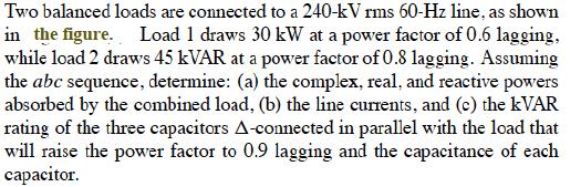
29 The total complex power N absorbed by the two loads is N = N + N N I L = I D = > A N = V L I D and the phase to phase current, I D flowing through each impedence of the connected laod, is I D = I L / (I L line current). I L I L
30 (Q C =Q C /). The the figure
31 Terminology Balanced current system Balanced load Balanced tension system Line tension Negative sequence Phase tension Positive sequence Three- phase electric system Sistema di correnti equilibrato Carico equilibrato Sistema simmetrico Tensioni concatenate Sequenza negativa (Sequenza indiretta) Tensioni d fase Sequenza positiva (Sequenza diretta) Sistema elettrico trifase
Three Phase Circuits
 Amin Electronics and Electrical Communications Engineering Department (EECE) Cairo University elc.n102.eng@gmail.com http://scholar.cu.edu.eg/refky/ OUTLINE Previously on ELCN102 Three Phase Circuits Balanced
Consider Figure What is the horizontal axis grid increment?
 Chapter Outline CHAPER 14 hree-phase Circuits and Power 14.1 What Is hree-phase? Why Is hree-phase Used? 14.2 hree-phase Circuits: Configurations, Conversions, Analysis 14.2.1 Delta Configuration Analysis
LO 1: Three Phase Circuits
 Course: EEL 2043 Principles of Electric Machines Class Instructor: Dr. Haris M. Khalid Email: hkhalid@hct.ac.ae Webpage: www.harismkhalid.com LO 1: Three Phase Circuits Three Phase AC System Three phase
THREE-PHASE CIRCUITS
 THR-HAS CIRCUITS 4.1 Introduction Generation, Transmission and distribution of electricity via the National Grid system is accomplished by three-phase alternating currents. The voltage induced by a single
Electric Circuit Theory
 Electric Circuit Theory Nam Ki Min nkmin@korea.ac.kr 010-9419-2320 Chapter 11 Sinusoidal Steady-State Analysis Nam Ki Min nkmin@korea.ac.kr 010-9419-2320 Contents and Objectives 3 Chapter Contents 11.1
Sinusoidal Steady State Analysis (AC Analysis) Part II
 Part II") Sinusoidal Steady State Analysis (AC Analysis) Part II Amin Electronics and Electrical Communications Engineering Department (EECE) Cairo University elc.n102.eng@gmail.com http://scholar.cu.edu.eg/refky/
Sinusoidal Steady State Analysis (AC Analysis) Part II Amin Electronics and Electrical Communications Engineering Department (EECE) Cairo University elc.n102.eng@gmail.com http://scholar.cu.edu.eg/refky/
Circuit Analysis-III. Circuit Analysis-II Lecture # 3 Friday 06 th April, 18
 Circuit Analysis-III Sinusoids Example #1 ü Find the amplitude, phase, period and frequency of the sinusoid: v (t ) =12cos(50t +10 ) Signal Conversion ü From sine to cosine and vice versa. ü sin (A ± B)
THREE-PHASE CIRCUITS. Historical Profiles
 C H A P T E R THREE-PHASE CIRCUITS 1 2 Society is never prepared to receive any invention. Every new thing is resisted, and it takes years for the inventor to get people to listen to him and years more
Chapter 2-3 Transformers
 Principles of Electric Machines and Power Electronics Chapter 2-3 Transformers Third Edition P. C. Sen Auto transformer Per unit system S b = S rate V b1 = V rate1 V b2 = V rate2 S b I b1 = = S rate =
Electric Circuits II Power Measurement. Dr. Firas Obeidat
 Electric Circuits II Power Measurement Dr. Firas Obeidat 1 Table of contents 1 Single-Phase Power Measurement 2 Three-Phase Power Measurement 2 Single-Phase Power Measurement The wattmeter is the instrument
Sinusoidal Steady State Analysis
 Sinusoidal Steady State Analysis 9 Assessment Problems AP 9. [a] V = 70/ 40 V [b] 0 sin(000t +20 ) = 0 cos(000t 70 ).. I = 0/ 70 A [c] I =5/36.87 + 0/ 53.3 =4+j3+6 j8 =0 j5 =.8/ 26.57 A [d] sin(20,000πt
1 Phasors and Alternating Currents
 Physics 4 Chapter : Alternating Current 0/5 Phasors and Alternating Currents alternating current: current that varies sinusoidally with time ac source: any device that supplies a sinusoidally varying potential
Chapter 33. Alternating Current Circuits
 Chapter 33 Alternating Current Circuits 1 Capacitor Resistor + Q = C V = I R R I + + Inductance d I Vab = L dt AC power source The AC power source provides an alternative voltage, Notation - Lower case
Consider a simple RC circuit. We might like to know how much power is being supplied by the source. We probably need to find the current.
 AC power Consider a simple RC circuit We might like to know how much power is being supplied by the source We probably need to find the current R 10! R 10! is VS Vmcosωt Vm 10 V f 60 Hz V m 10 V C 150
Sinusoidal Steady-State Analysis
 Chapter 4 Sinusoidal Steady-State Analysis In this unit, we consider circuits in which the sources are sinusoidal in nature. The review section of this unit covers most of section 9.1 9.9 of the text.
Three-phase AC Circuits. Measurement of Power in a Three-phase Circuit
 Three-phase AC Circuits Lesson Measurement of Power in a Three-phase Circuit In the previous lesson, the phase and line currents for balanced delta-connected load fed from a three-phase supply, along with
Refresher course on Electrical fundamentals (Basics of A.C. Circuits) by B.M.Vyas
 by B.M.Vyas") Refresher course on Electrical fundamentals (Basics of A.C. Circuits) by B.M.Vyas A specifically designed programme for Da Afghanistan Breshna Sherkat (DABS) Afghanistan 1 Areas Covered Under this Module
Refresher course on Electrical fundamentals (Basics of A.C. Circuits) by B.M.Vyas A specifically designed programme for Da Afghanistan Breshna Sherkat (DABS) Afghanistan 1 Areas Covered Under this Module
Three Phase Systems 295
 Three Phase Systems 95 9. MEASUEMENT OF POE Star-Connected Balanced Load with Neutral Point Power can be measured in this case by connecting a single wattmeter with its current coil in one line and the
VTU E-LEARNING NOTES ON:
 VTU E-LEARNING NOTES ON: 10EE35 ELECTRICAL AND ELECTRONIC MEASUREMENTS AND INSTRUMENTATION BY DR. M.S. RAVIPRAKASHA PROFESSOR & HEAD DEPT. OF E&E ENGG. MALNAD COLLEGE OF ENGG. HASSAN 573 201. SUBJECT CODE
Basics of Electric Circuits
 António Dente Célia de Jesus February 2014 1 Alternating Current Circuits 1.1 Using Phasors There are practical and economic reasons justifying that electrical generators produce emf with alternating and
Lecture 9 Time Domain vs. Frequency Domain
 . Topics covered Lecture 9 Time Domain vs. Frequency Domain (a) AC power in the time domain (b) AC power in the frequency domain (c) Reactive power (d) Maximum power transfer in AC circuits (e) Frequency
Chapter 12: Three-Phase Circuits
 Chater 1: Three-Phase Circuits 1.1 ntroduction 1. Balanced Three-Phase oltages 1.3 Balanced Wye-Wye connection 1.4 Balanced Wye-Delta Connection 1.7 Power in a Balanced System 1.1 NTRODUCTON A single-hase
Module 4. Single-phase AC Circuits
 Module 4 Single-phase AC Circuits Lesson 14 Solution of Current in R-L-C Series Circuits In the last lesson, two points were described: 1. How to represent a sinusoidal (ac) quantity, i.e. voltage/current
Lecture 11 - AC Power
 - AC Power 11/17/2015 Reading: Chapter 11 1 Outline Instantaneous power Complex power Average (real) power Reactive power Apparent power Maximum power transfer Power factor correction 2 Power in AC Circuits
Alternating Current Circuits
 Alternating Current Circuits AC Circuit An AC circuit consists of a combination of circuit elements and an AC generator or source. The output of an AC generator is sinusoidal and varies with time according
Power and Energy Measurement
 Power and Energy Measurement ENE 240 Electrical and Electronic Measurement Class 11, February 4, 2009 werapon.chi@kmutt.ac.th 1 Work, Energy and Power Work is an activity of force and movement in the direction
Single Phase Parallel AC Circuits
 Single Phase Parallel AC Circuits 1 Single Phase Parallel A.C. Circuits (Much of this material has come from Electrical & Electronic Principles & Technology by John Bird) n parallel a.c. circuits similar
Balanced three-phase systems and operation
 ELEC0014 - Introduction to power and energy systems Balanced three-phase systems and operation Thierry Van Cutsem t.vancutsem@ulg.ac.be www.montefiore.ulg.ac.be/~vct October 2017 1 / 17 system used for
mywbut.com Lesson 16 Solution of Current in AC Parallel and Seriesparallel
 esson 6 Solution of urrent in Parallel and Seriesparallel ircuits n the last lesson, the following points were described:. How to compute the total impedance/admittance in series/parallel circuits?. How
Chapter 10: Sinusoidal Steady-State Analysis
 Chapter 10: Sinusoidal Steady-State Analysis 1 Objectives : sinusoidal functions Impedance use phasors to determine the forced response of a circuit subjected to sinusoidal excitation Apply techniques
Power Factor Improvement
 Salman bin AbdulazizUniversity College of Engineering Electrical Engineering Department EE 2050Electrical Circuit Laboratory Power Factor Improvement Experiment # 4 Objectives: 1. To introduce the concept
ECE 421/521 Electric Energy Systems Power Systems Analysis I 2 Basic Principles. Instructor: Kai Sun Fall 2013
 ECE 41/51 Electric Energy Systems Power Systems Analysis I Basic Principles Instructor: Kai Sun Fall 013 1 Outline Power in a 1-phase AC circuit Complex power Balanced 3-phase circuit Single Phase AC System
BASIC NETWORK ANALYSIS
 SECTION 1 BASIC NETWORK ANALYSIS A. Wayne Galli, Ph.D. Project Engineer Newport News Shipbuilding Series-Parallel dc Network Analysis......................... 1.1 Branch-Current Analysis of a dc Network......................
ALTERNATING CURRENT
 ATENATING UENT Important oints:. The alternating current (A) is generally expressed as ( ) I I sin ω t + φ Where i peak value of alternating current.. emf of an alternating current source is generally
ECE 420. Review of Three Phase Circuits. Copyright by Chanan Singh, Panida Jirutitijaroen, and Hangtian Lei, For educational use only-not for sale.
 ECE 40 Review of Three Phase Circuits Outline Phasor Complex power Power factor Balanced 3Ф circuit Read Appendix A Phasors and in steady state are sinusoidal functions with constant frequency 5 0 15 10
THREE PHASE SYSTEMS Part 1
 ERT105: ELECTRCAL TECHNOLOGY CHAPTER 3 THREE PHASE SYSTEMS Part 1 1 Objectives Become familiar with the operation of a three phase generator and the magnitude and phase relationship. Be able to calculate
12 Chapter Driven RLC Circuits
 hapter Driven ircuits. A Sources... -. A ircuits with a Source and One ircuit Element... -3.. Purely esistive oad... -3.. Purely Inductive oad... -6..3 Purely apacitive oad... -8.3 The Series ircuit...
Module 4. Single-phase AC circuits. Version 2 EE IIT, Kharagpur
 Module 4 Single-phase circuits ersion EE T, Kharagpur esson 6 Solution of urrent in Parallel and Seriesparallel ircuits ersion EE T, Kharagpur n the last lesson, the following points were described:. How
Sinusoidal Response of RLC Circuits
 Sinusoidal Response of RLC Circuits Series RL circuit Series RC circuit Series RLC circuit Parallel RL circuit Parallel RC circuit R-L Series Circuit R-L Series Circuit R-L Series Circuit Instantaneous
BASIC PRINCIPLES. Power In Single-Phase AC Circuit
 BASIC PRINCIPLES Power In Single-Phase AC Circuit Let instantaneous voltage be v(t)=v m cos(ωt+θ v ) Let instantaneous current be i(t)=i m cos(ωt+θ i ) The instantaneous p(t) delivered to the load is p(t)=v(t)i(t)=v
CHAPTER 22 ELECTROMAGNETIC INDUCTION
 CHAPTER 22 ELECTROMAGNETIC INDUCTION PROBLEMS 47. REASONING AND Using Equation 22.7, we find emf 2 M I or M ( emf 2 ) t ( 0.2 V) ( 0.4 s) t I (.6 A) ( 3.4 A) 9.3 0 3 H 49. SSM REASONING AND From the results
EE292: Fundamentals of ECE
 EE292: Fundamentals of ECE Fall 2012 TTh 10:00-11:15 SEB 1242 Lecture 18 121025 http://www.ee.unlv.edu/~b1morris/ee292/ 2 Outline Review RMS Values Complex Numbers Phasors Complex Impedance Circuit Analysis
Sinusoids and Phasors
 CHAPTER 9 Sinusoids and Phasors We now begins the analysis of circuits in which the voltage or current sources are time-varying. In this chapter, we are particularly interested in sinusoidally time-varying
Power Systems - Basic Concepts and Applications - Part I
 PDHonline Course E104 (1 PDH) Power ystems Basic Concepts and Applications Part I Instructor: hihmin Hsu PhD PE 01 PDH Online PDH Center 57 Meadow Estates Drive Fairfax A 006658 Phone & Fax: 709880088
REACTANCE. By: Enzo Paterno Date: 03/2013
 REACTANCE REACTANCE By: Enzo Paterno Date: 03/2013 5/2007 Enzo Paterno 1 RESISTANCE - R i R (t R A resistor for all practical purposes is unaffected by the frequency of the applied sinusoidal voltage or
Module 4. Single-phase AC Circuits. Version 2 EE IIT, Kharagpur 1
 Module 4 Single-phase A ircuits ersion EE IIT, Kharagpur esson 4 Solution of urrent in -- Series ircuits ersion EE IIT, Kharagpur In the last lesson, two points were described:. How to represent a sinusoidal
Electrical Circuits Lab Series RC Circuit Phasor Diagram
 Electrical Circuits Lab. 0903219 Series RC Circuit Phasor Diagram - Simple steps to draw phasor diagram of a series RC circuit without memorizing: * Start with the quantity (voltage or current) that is
Chapter 5 Steady-State Sinusoidal Analysis
 Chapter 5 Steady-State Sinusoidal Analysis Chapter 5 Steady-State Sinusoidal Analysis 1. Identify the frequency, angular frequency, peak value, rms value, and phase of a sinusoidal signal. 2. Solve steady-state
Course Updates. Reminders: 1) Assignment #10 due Today. 2) Quiz # 5 Friday (Chap 29, 30) 3) Start AC Circuits
 Assignment #10 due Today. 2) Quiz # 5 Friday (Chap 29, 30) 3) Start AC Circuits") ourse Updates http://www.phys.hawaii.edu/~varner/phys272-spr10/physics272.html eminders: 1) Assignment #10 due Today 2) Quiz # 5 Friday (hap 29, 30) 3) Start A ircuits Alternating urrents (hap 31) In this
ourse Updates http://www.phys.hawaii.edu/~varner/phys272-spr10/physics272.html eminders: 1) Assignment #10 due Today 2) Quiz # 5 Friday (hap 29, 30) 3) Start A ircuits Alternating urrents (hap 31) In this
2 Signal Frequency and Impedances First Order Filter Circuits Resonant and Second Order Filter Circuits... 13
 Lecture Notes: 3454 Physics and Electronics Lecture ( nd Half), Year: 7 Physics Department, Faculty of Science, Chulalongkorn University //7 Contents Power in Ac Circuits Signal Frequency and Impedances
Physics-272 Lecture 20. AC Power Resonant Circuits Phasors (2-dim vectors, amplitude and phase)
") Physics-7 ecture 0 A Power esonant ircuits Phasors (-dim vectors, amplitude and phase) What is reactance? You can think of it as a frequency-dependent resistance. 1 ω For high ω, χ ~0 - apacitor looks
Physics-7 ecture 0 A Power esonant ircuits Phasors (-dim vectors, amplitude and phase) What is reactance? You can think of it as a frequency-dependent resistance. 1 ω For high ω, χ ~0 - apacitor looks
EE 3120 Electric Energy Systems Study Guide for Prerequisite Test Wednesday, Jan 18, pm, Room TBA
 EE 3120 Electric Energy Systems Study Guide for Prerequisite Test Wednesday, Jan 18, 2006 6-7 pm, Room TBA First retrieve your EE2110 final and other course papers and notes! The test will be closed book
Analysis of AC Power RMS and Phasors Power Factor. Power Factor. Eduardo Campero Littlewood
 Power Factor Eduardo Campero Littlewood Universidad Autónoma Metropolitana Azcapotzalco Campus Energy Department Content 1 Analysis of AC Power 2 RMS and Phasors 3 Power Factor Recommended Bibliography
I. Impedance of an R-L circuit.
 I. Impedance of an R-L circuit. [For inductor in an AC Circuit, see Chapter 31, pg. 1024] Consider the R-L circuit shown in Figure: 1. A current i(t) = I cos(ωt) is driven across the circuit using an AC
Grunntækni og rafmagn í riðstraums (AC) raforkukerfi
 raforkukerfi") VÉL102M - Orkufrek framleiðsluferli - Egill Benedikt Hreinsson 1 Grunntækni og rafmagn í riðstraums (AC) raforkukerfi Haust 2016 VÉL102M - Orkufrek framleiðsluferli - Egill Benedikt Hreinsson 2 Samræmi
VÉL102M - Orkufrek framleiðsluferli - Egill Benedikt Hreinsson 1 Grunntækni og rafmagn í riðstraums (AC) raforkukerfi Haust 2016 VÉL102M - Orkufrek framleiðsluferli - Egill Benedikt Hreinsson 2 Samræmi
12. Introduction and Chapter Objectives
 Real Analog - Circuits 1 Chapter 1: Steady-State Sinusoidal Power 1. Introduction and Chapter Objectives In this chapter we will address the issue of power transmission via sinusoidal or AC) signals. This
B.E. / B.Tech. Degree Examination, April / May 2010 Sixth Semester. Electrical and Electronics Engineering. EE 1352 Power System Analysis
 B.E. / B.Tech. Degree Examination, April / May 2010 Sixth Semester Electrical and Electronics Engineering EE 1352 Power System Analysis (Regulation 2008) Time: Three hours Answer all questions Part A (10
UNIT- I Phase Sequence:
 UNIT- I Phase Sequence: Phase sequence refers to the relation between voltages (or currents, as well) in a three-phase system. The common representation of this relation is in terms of a phasor diagram,
Chapter 10: Sinusoids and Phasors
 Chapter 10: Sinusoids and Phasors 1. Motivation 2. Sinusoid Features 3. Phasors 4. Phasor Relationships for Circuit Elements 5. Impedance and Admittance 6. Kirchhoff s Laws in the Frequency Domain 7. Impedance
SINUSOIDAL STEADY STATE CIRCUIT ANALYSIS
 SINUSOIDAL STEADY STATE CIRCUIT ANALYSIS 1. Introduction A sinusoidal current has the following form: where I m is the amplitude value; ω=2 πf is the angular frequency; φ is the phase shift. i (t )=I m.sin
ELECTRIC POWER CIRCUITS BASIC CONCEPTS AND ANALYSIS
 Contents ELEC46 Power ystem Analysis Lecture ELECTRC POWER CRCUT BAC CONCEPT AND ANALY. Circuit analysis. Phasors. Power in single phase circuits 4. Three phase () circuits 5. Power in circuits 6. ingle
Generation, transmission and distribution, as well as power supplied to industrial and commercial customers uses a 3 phase system.
 Three-phase Circuits Generation, transmission and distribution, as well as power supplied to industrial and commercial customers uses a 3 phase system. Where 3 voltages are supplied of equal magnitude,
Lecture 3: Three-phase power circuits
 1/24/28 Lecture : Three-phase power circuits 1 nstructor: Dr. Gleb. Tcheslavski Contact: gleb@ee.lamar.edu Office Hours: TBD; Room 2 Class web site: MyLamar ntroduction 2 Almost all electric power generation
Transformer Fundamentals
 Transformer Fundamentals 1 Introduction The physical basis of the transformer is mutual induction between two circuits linked by a common magnetic field. Transformer is required to pass electrical energy
Chapter 21: RLC Circuits. PHY2054: Chapter 21 1
 Chapter 21: RC Circuits PHY2054: Chapter 21 1 Voltage and Current in RC Circuits AC emf source: driving frequency f ε = ε sinωt ω = 2π f m If circuit contains only R + emf source, current is simple ε ε
Power and Energy Measurement
 Power and Energy Measurement EIE 240 Electrical and Electronic Measurement April 24, 2015 1 Work, Energy and Power Work is an activity of force and movement in the direction of force (Joules) Energy is
Week No. 6 Chapter Six: Power Factor Improvement
 Week No. 6 Chapter Six: Power Factor Improvement The electrical energy is almost wholly generated, transmitted and distributed in the form of alternating current. Therefore, the question of power factor
Homework 2 SJTU233. Part A. Part B. Problem 2. Part A. Problem 1. Find the impedance Zab in the circuit seen in the figure. Suppose that R = 5 Ω.
 Homework 2 SJTU233 Problem 1 Find the impedance Zab in the circuit seen in the figure. Suppose that R = 5 Ω. Express Zab in polar form. Enter your answer using polar notation. Express argument in degrees.
Chapter 9 Objectives
 Chapter 9 Engr8 Circuit Analysis Dr Curtis Nelson Chapter 9 Objectives Understand the concept of a phasor; Be able to transform a circuit with a sinusoidal source into the frequency domain using phasor
Series & Parallel Resistors 3/17/2015 1
 Series & Parallel Resistors 3/17/2015 1 Series Resistors & Voltage Division Consider the single-loop circuit as shown in figure. The two resistors are in series, since the same current i flows in both
Circuit Theorems Overview Linearity Superposition Source Transformation Thévenin and Norton Equivalents Maximum Power Transfer
 Circuit Theorems Overview Linearity Superposition Source Transformation Thévenin and Norton Equivalents Maximum Power Transfer J. McNames Portland State University ECE 221 Circuit Theorems Ver. 1.36 1
Lecture 05 Power in AC circuit
 CA2627 Building Science Lecture 05 Power in AC circuit Instructor: Jiayu Chen Ph.D. Announcement 1. Makeup Midterm 2. Midterm grade Grade 25 20 15 10 5 0 10 15 20 25 30 35 40 Grade Jiayu Chen, Ph.D. 2
Lectures 16 & 17 Sinusoidal Signals, Complex Numbers, Phasors, Impedance & AC Circuits. Nov. 7 & 9, 2011
 Lectures 16 & 17 Sinusoidal Signals, Complex Numbers, Phasors, Impedance & AC Circuits Nov. 7 & 9, 2011 Material from Textbook by Alexander & Sadiku and Electrical Engineering: Principles & Applications,
Physics 142 AC Circuits Page 1. AC Circuits. I ve had a perfectly lovely evening but this wasn t it. Groucho Marx
 Physics 142 A ircuits Page 1 A ircuits I ve had a perfectly lovely evening but this wasn t it. Groucho Marx Alternating current: generators and values It is relatively easy to devise a source (a generator
Notes on Electric Circuits (Dr. Ramakant Srivastava)
") Notes on Electric ircuits (Dr. Ramakant Srivastava) Passive Sign onvention (PS) Passive sign convention deals with the designation of the polarity of the voltage and the direction of the current arrow
Notes on Electric ircuits (Dr. Ramakant Srivastava) Passive Sign onvention (PS) Passive sign convention deals with the designation of the polarity of the voltage and the direction of the current arrow
Sinusoidal Steady State Analysis (AC Analysis) Part I
 Part I") Sinusoidal Steady State Analysis (AC Analysis) Part I Amin Electronics and Electrical Communications Engineering Department (EECE) Cairo University elc.n102.eng@gmail.com http://scholar.cu.edu.eg/refky/
Sinusoidal Steady State Analysis (AC Analysis) Part I Amin Electronics and Electrical Communications Engineering Department (EECE) Cairo University elc.n102.eng@gmail.com http://scholar.cu.edu.eg/refky/
Toolbox: Electrical Systems Dynamics
 Toolbox: Electrical Systems Dynamics Dr. John C. Wright MIT - PSFC 05 OCT 2010 Introduction Outline Outline AC and DC power transmission Basic electric circuits Electricity and the grid Image removed due
University of Jordan Faculty of Engineering & Technology Electric Power Engineering Department
 University of Jordan Faculty of Engineering & Technology Electric Power Engineering Department EE471: Electrical Machines-II Tutorial # 2: 3-ph Induction Motor/Generator Question #1 A 100 hp, 60-Hz, three-phase
Driven RLC Circuits Challenge Problem Solutions
 Driven LC Circuits Challenge Problem Solutions Problem : Using the same circuit as in problem 6, only this time leaving the function generator on and driving below resonance, which in the following pairs
ALTERNATING CURRENT. with X C = 0.34 A. SET UP: The specified value is the root-mean-square current; I. EXECUTE: (a) V = (0.34 A) = 0.12 A.
 V = (0.34 A) = 0.12 A.") ATENATING UENT 3 3 IDENTIFY: i Icosωt and I I/ SET UP: The specified value is the root-mean-square current; I 34 A EXEUTE: (a) I 34 A (b) I I (34 A) 48 A (c) Since the current is positive half of the time
ATENATING UENT 3 3 IDENTIFY: i Icosωt and I I/ SET UP: The specified value is the root-mean-square current; I 34 A EXEUTE: (a) I 34 A (b) I I (34 A) 48 A (c) Since the current is positive half of the time
EE313 Fall 2013 Exam #1 (100 pts) Thursday, September 26, 2013 Name. 1) [6 pts] Convert the following time-domain circuit to the RMS Phasor Domain.
![EE313 Fall 2013 Exam #1 (100 pts) Thursday, September 26, 2013 Name. 1) [6 pts] Convert the following time-domain circuit to the RMS Phasor Domain.](/thumbs/95/123488230.jpg "EE313 Fall 2013 Exam #1 (100 pts) Thursday, September 26, 2013 Name. 1) [6 pts] Convert the following time-domain circuit to the RMS Phasor Domain.") Name If you have any questions ask them. Remember to include all units on your answers (V, A, etc). Clearly indicate your answers. All angles must be in the range 0 to +180 or 0 to 180 degrees. 1) [6 pts]
Name If you have any questions ask them. Remember to include all units on your answers (V, A, etc). Clearly indicate your answers. All angles must be in the range 0 to +180 or 0 to 180 degrees. 1) [6 pts]
ECE 1311: Electric Circuits. Chapter 2: Basic laws
 ECE 1311: Electric Circuits Chapter 2: Basic laws Basic Law Overview Ideal sources series and parallel Ohm s law Definitions open circuits, short circuits, conductance, nodes, branches, loops Kirchhoff's
Work, Energy and Power
 1 Work, Energy and Power Work is an activity of force and movement in the direction of force (Joules) Energy is the capacity for doing work (Joules) Power is the rate of using energy (Watt) P = W / t,
Chapter 10 AC Analysis Using Phasors
 Chapter 10 AC Analysis Using Phasors 10.1 Introduction We would like to use our linear circuit theorems (Nodal analysis, Mesh analysis, Thevenin and Norton equivalent circuits, Superposition, etc.) to
Learnabout Electronics - AC Theory
 Learnabout Electronics - AC Theory Facts & Formulae for AC Theory www.learnabout-electronics.org Contents AC Wave Values... 2 Capacitance... 2 Charge on a Capacitor... 2 Total Capacitance... 2 Inductance...
Chapter 1W Basic Electromagnetic Concepts
 Chapter 1W Basic Electromagnetic Concepts 1W Basic Electromagnetic Concepts 1W.1 Examples and Problems on Electric Circuits 1W.2 Examples on Magnetic Concepts This chapter includes additional examples
11. AC Circuit Power Analysis
 . AC Circuit Power Analysis Often an integral part of circuit analysis is the determination of either power delivered or power absorbed (or both). In this chapter First, we begin by considering instantaneous
Pre-Lab. Introduction
 Pre-Lab Read through this entire lab. Perform all of your calculations (calculated values) prior to making the required circuit measurements. You may need to measure circuit component values to obtain
Chapter 8: Unsymmetrical Faults
 Chapter 8: Unsymmetrical Faults Introduction The sequence circuits and the sequence networks developed in the previous chapter will now be used for finding out fault current during unsymmetrical faults.
Sinusoidal Steady State Power Calculations
 10 Sinusoidal Steady State Power Calculations Assessment Problems AP 10.1 [a] V = 100/ 45 V, Therefore I = 20/15 A P = 1 (100)(20)cos[ 45 (15)] = 500W, 2 A B Q = 1000sin 60 = 866.03 VAR, B A [b] V = 100/
EE301 Three Phase Power
 Learning Objectives a. Compute the real, reactive and apparent power in three phase systems b. Calculate currents and voltages in more challenging three phase circuit arrangements c. Apply the principles
EKT103 ELECTRICAL ENGINEERING
 EKT13 EECTRCA ENGNEERNG Chater 1 Three-Phase System 1 COURSE OUTCOME (CO) CO1: Ability to define and exlain the concet of single-hase and threehase system. 2 Revision A sinusoid is a signal that has the
TECHNICAL BULLETIN 006 Symmetrical Components Overview. Introduction. I a g I b g I c
 Introduction The method of symmetrical components is a mathematical technique that allows the engineer to solve unbalanced systems using balanced techniques. Developed by C. Fortescue and presented in
EEE3405 ELECTRICAL ENGINEERING PRINCIPLES 2 - TEST
 ATTEMPT ALL QUESTIONS (EACH QUESTION 20 Marks, FULL MAKS = 60) Given v 1 = 100 sin(100πt+π/6) (i) Find the MS, period and the frequency of v 1 (ii) If v 2 =75sin(100πt-π/10) find V 1, V 2, 2V 1 -V 2 (phasor)
RLC Circuit (3) We can then write the differential equation for charge on the capacitor. The solution of this differential equation is
 We can then write the differential equation for charge on the capacitor. The solution of this differential equation is") RLC Circuit (3) We can then write the differential equation for charge on the capacitor The solution of this differential equation is (damped harmonic oscillation!), where 25 RLC Circuit (4) If we charge
RLC Circuit (3) We can then write the differential equation for charge on the capacitor The solution of this differential equation is (damped harmonic oscillation!), where 25 RLC Circuit (4) If we charge
Chapter 2. Engr228 Circuit Analysis. Dr Curtis Nelson
 Chapter 2 Engr228 Circuit Analysis Dr Curtis Nelson Chapter 2 Objectives Understand symbols and behavior of the following circuit elements: Independent voltage and current sources; Dependent voltage and
MCE603: Interfacing and Control of Mechatronic Systems. Chapter 1: Impedance Analysis for Electromechanical Interfacing
 MCE63: Interfacing and Control of Mechatronic Systems Chapter 1: Impedance Analysis for Electromechanical Interfacing Part B: Input and Output Impedance Cleveland State University Mechanical Engineering
PHYS Fields and Waves
 PHYS 2421 - Fields and Waves Idea: how to deal with alternating currents Edison wanted direct current, Tesla alternating current, who won? Mathematically: Instantaneous current: Instantaneous voltage:
Transformer. Transformer comprises two or more windings coupled by a common magnetic circuit (M.C.).
.") . Transformers Transformer Transformer comprises two or more windings coupled by a common magnetic circuit (M.C.). f the primary side is connected to an AC voltage source v (t), an AC flux (t) will be
. Transformers Transformer Transformer comprises two or more windings coupled by a common magnetic circuit (M.C.). f the primary side is connected to an AC voltage source v (t), an AC flux (t) will be
Chapter 2 Power System Fundamentals: Balanced Three-Phase Circuits
 Chapter 2 Power System Fundamentals: Balanced Three-Phase Circuits This chapter reviews the fundamentals of balanced three-phase alternating current (ac) circuits. First, we define positive and negative