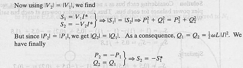
ECE 421/521 Electric Energy Systems Power Systems Analysis I 2 Basic Principles. Instructor: Kai Sun Fall 2013
|
|
|
- Bartholomew Maxwell
- 5 years ago
- Views:
Transcription
1 ECE 41/51 Electric Energy Systems Power Systems Analysis I Basic Principles Instructor: Kai Sun Fall 013 1
2 Outline Power in a 1-phase AC circuit Complex power Balanced 3-phase circuit
3 Single Phase AC System it ( ) = I cos( ωt+ θ ) m i + vt ( ) = Vm cos( ωt+ θv) - Z Load 3
4 Phasor Representation vt ( ) = V cos( ωt+ θ ) = V cos( ωt+ θ ) m v v it ( ) = I cos( ωt+ θ ) = I cos( ωt+ θ ) m i i V= V θ v I= I θ i RMS phasors of v(t) and i(t) Reference A phasor is a complex number that carries the amplitude and phase angle information of a sinusoidal function Phasors represent sinusoidal signals of a common frequency (ω) as vectors in the complex plane w.r.t. a chosen reference signal. Phasor representation is a mapping from the time domain to complex number domain. 4
5 Instantaneous power delivered to the load: Using trigonometric identity 1 cos Acos B = cos( A- B) + cos( A+ B) θ = θ θ v V = V /, I = I / m [ ] i Impedance angle >0 for inductive load and <0 for capacitive load Root-mean-square (RMS) values m pt () = vtit ()() = VI cos( ωt+ θ )cos( ωt+ θ ) m m v i 1 = VmIm[ cos( θv θi) + cos( ωt + θv + θi) ] 1 = VmIm{ cos( θv θi) + cos[( ωt + θv) ( θv θi)] } 1 = VmIm{ cosθ + cos[( ωt + θv) θ] } 1 = VmIm[ cosθ + cos ( ωt + θv) cosθ + sin ( ωt + θv) sinθ ] p( t) = V I cos θ[1 + cos ( ωt + θv)] + V I sinθsin ( ωt + θv) p () t p () t R X 5
6 Example.1 Assume vt ( ) = 100cosωt Z = Ω Calculate the RMS current phasor: I = = o it ( ) = 80cos( ωt 60 ) 100 v(t)=v m cos ωt, i(t)=i m cos(ωt -60) 6000 p(t)=v(t) i(t) ωt, degree p R (t) Eq ωt, degree p X (t) Eq ωt, degree ωt, degree 6
7 p( t) = V I cos θ[1 + cos ( ωt + θv)] + V I sinθsin ( ωt + θv) p () t p () t R X Observations on p R (t): Oscillating at frequency *ω (twice of the source frequency) Changing between 0 and V I cosθ (always positive) Average value is V I cosθ It is the energy flow into the circuit Observations on p X (t): Oscillating at frequency *ω (twice of the source frequency) Changing between - V I sinθ and V I sinθ (either positive or negative) Average value is zero It is the energy borrowed & returned by the circuit. It does no useful work in the load but takes some line capacity 7
![Real and Reactive Powers p( t) = V I cos θ[1 + cos ( ωt + θv)] + V I sinθsin ( ωt + θv) V I Apparent power def P = V I cosθ Real power or active power (average power) Unit ~ watt or W p () t p () t](/docs-images/88/114789056/images/8-0.jpg "Unit ~ volt ampere or VA (kva or MVA) Power factor (PF): cosθ= cos(θ v -θ i ) R Lagging or leading when θ =θ v -θ i >0 or <0 X Q P def Q = V I sinθ Reactive power Unit ~ var (volt-ampere reactive).")
8 Real and Reactive Powers p( t) = V I cos θ[1 + cos ( ωt + θv)] + V I sinθsin ( ωt + θv) V I Apparent power def P = V I cosθ Real power or active power (average power) Unit ~ watt or W p () t p () t Unit ~ volt ampere or VA (kva or MVA) Power factor (PF): cosθ= cos(θ v -θ i ) R Lagging or leading when θ =θ v -θ i >0 or <0 X Q P def Q = V I sinθ Reactive power Unit ~ var (volt-ampere reactive). Some people use Var, VAR or VAr Q>0 or <0 when θ=θ v -θ i >0 or <0 8
9 Characteristics of instantaneous power p(t) p( t) = V I cos θ[1 + cos ( ωt+ θv)] + V I sinθsin ( ωt+ θv) For a pure resistor load (thermal load), θ=θ v -θ i =0, PF=1 (unity PF) P= V I, so all electric energy becomes thermal energy For a pure inductive load, θ=θ v -θ i =90, PF=0 P=0, so electric energy = constant (no transformation to other forms) p(t) oscillates between the source and the magnetic field associated with the inductive load For a pure capacitive load, θ=θ v -θ i =-90, PF=0 p () t p () t R = P[1 + cos ( ωt+ θ )] + Qsin ( ωt+ θ ) v P=0, so electric energy = constant (no transformation to other forms) p(t) oscillates between the source and the electric field associated with the capacitive load v X 9
10 Example.1 Z = Ω vt ( ) = 100cosωt o it ( ) = 80cos( ωt 60 ) RMS phasors: V = 0, I = 60 o o p( t) = V I cos θ[1 + cos ωt] + V I sinθsin ωt = 4000cos 60 [1 + cos ωt] sin 60 sin ωt () p () () () pr t X t pr t px t P Q 100 v(t)=v m cos ωt, i(t)=i m cos(ωt -60) 6000 p(t)=v(t) i(t) P ωt, degree 4000 p R (t) Eq ωt, degree 4000 p X (t) Eq P ωt, degree ωt, degree Borrowing Returning Q Q
11 What does absorbing or generating reactive power mean? Reactive power with a circuit element does not lead to real energy consumption Starting from the time of v(t)=v m, An inductive element (lagging PF) first absorbs and then returns the same amount of electric energy. Such a pattern is considered absorbing reactive power, and it helps reduce oscillations of power A capacitive element (leading PF) first generates and then absorbs the same amount of electric energy. Such a pattern is considered generating reactive power, and it helps maintain voltage For a real-world power system with long-distance transmission, low voltage at receiving ends is usually a big reliability concern. Shunt/series capacitors can be added as sources of reactive power or var 11
12 Complex Power def S = P + jq = V I cosθ + jv I sinθ = V I θ = V I θ θ = VI v i * = S θ = P + Q θ Reference S is the apparent power θ=tan -1 (Q/P) When θ>0 (θ i <θ v, i.e. lagging PF), Q>0 i.e. absorbing Q (inductive load) When θ<0 (θ i >θ v, i.e. leading PF), Q<0 i.e. generating Q (capacitive load) 1
13 PF=cosθ=P/ S (lagging/leading is told by +/- sign of Q) P= S cosθ= S PF = Q= = S sin θ S 1 PF, if lagging S sin θ S 1 PF, if leading If the load impedance is Z, i.e.v=zi, then S = VI * = ZII * = Z I = R I +jx I = P + jq P=R I Q=X I Z R X The load impedance angle θ is also called power angle (ϕ in some literature) Apparent power S I indicates heating and is used as a rating unit of power equipment 13
14 Some useful equations: * * VV V * * * S = VI = = = V Y Z Z Z = V S * Y = S V * If Z is purely resistive P = V R If Z is purely reactive Q V V V = = or X ωl 1/ ωc 14
15 Complex Power Balance S = VI = V[ I + I + I ] = VI + VI + VI = S + S + S * * * * P + jq = P + jq + P + jq + P + jq Due to the conservation of energy, the total complex power delivered to the loads in parallel is the sum of complex powers delivered to each (by KCL). In other words, a balance must be maintained all the time for both real power and reactive power 15
16 Example. V = V, Z = 60 + j0 Ω, Z = 6 + j1 Ω, Z = 30 j30ω 3 1 Find the power absorbed by each load and the total complex power I I I 1 3 V = = = = 0 + j0 A Z j0 60 V (1 j) = = = = = 40 j80 A Z 6 + j1 1+ j 5 V (1 + j) = = = = = 0 + j0 A Z 30 j30 1 j 3 S = VI = (0 j0) = 4, 000 W+ j0 var * 1 1 * * 3 3 S = VI = (40 + j80) = 48, 000 W+ j96, 000 var S = VI = (0 j0) = 4, 000 W j4, 000 var S = S1 + S + S3 = 96,000 W+ j7,000 var 16
17 Other approaches I = I + I + I = (0 + j0) + (40 j80) + (0 + j0) 1 3 = 80 j60 = A S (100 0 )( ) 10, VA * = VI = = = 96,000 W + j7,000 var S S S V (100) = = = 4,000 W + j0 var 60 1 * Z1 V (100) = = = 48,000 W + j96,000 var 6 j1 * Z V (100) = = = 4,000 W j4,000 var 30 + j30 3 * Z3 17
18 Theorem of Conservation of Complex Power For a network supplied by independent sources all at the same frequency (all voltages and currents are assumed to be sinusoids), the sum of the complex power supplied by the independent sources equals the sum of the complex power received by all the other branches of the network For a single source with elements in series or parallel, it is proved by Kirchhoff s voltage or current law (KVL/KCL) For a general case, it is proved by Tellegen s theorem. Application of the theorem: a part of the network can be replaced by an equivalent independent source 18

19 Some examples on Bergen and Vittal s book 19

20 0
21 1
22 Homework # Read through Saadat s Chapter.1~.4 ECE51:.1~.6 ECE41:.1,.3,.4,.5 Due date: 9/11 (Wednesday) submitted in class or by
23 Power Factor Correction P= V I cosθ= S PF When PF<1, current I needs to increase by 1/PF to deliver the same P as that with PF=1. Thus, the major loads of the system are expected to have close to unity PFs. That is not a problem for residential and small commercial customers. However, industrial loads are inductive with low lagging PFs, so capacitors may be installed to improve PFs 3
24 Example.3 P+jQ (a) (b) Find P, Q, I and PF at the source Find capacitance C of the shunt capacitor to improve the overall PF to 0.8 lagging C Solution: (a) I I = = 0 A = = 4 j8 A 10 + j0 S = VI = 00 0 ( j0) = 400 W+ j0 var * 1 1 S = VI = 00 0 (4 + j8) = 800 W + j1600 var * S = P + jq = j1600 = VA * S I = = = A * V 00 0 PF = cos(53.13 ) = 0.6 lagging 4 (b) New power angle θ 1 = cos (0.8) = Q = P tanθ = 100 tan(36.87 ) = 900 var Q Z c c = = 700 var V (00) = = = j57.14 Ω S j700 * c 6 10 C = = 46.4 μf π (60)(57.14)

25 New apparent power and current S = j900 = * S I = = = * V Learn Example.4 (high-voltage) High-voltage capacitor bank (150kV - 75MVAR) (Source: wikipedia.org) 5
26 Complex Power Flow V1 = V1 δ1 V = V δ P 1 +jq 1 P 1 +jq 1 I 1 = V δ V δ 1 1 Z γ V1 V = δ1 γ δ γ Z Z * V1 V S1 = VI 1 1 = V1 δ 1[ 1 ] Z γ δ Z γ δ V1 V1 V = γ γ + δ1 δ Z Z P V V V = cosγ cos( γ + δ δ ) Z Z Q V V V = sin γ sin( γ + δ δ ) Z Z If R=0, i.e. Z =X and γ=90 o P V V = sin( δ δ ) X V1 Q1 = [ V1 V cos( δ1 δ )] X 6
27 P V V = sin( δ δ ) X V1 Q1 = [ V1 V cos( δ1 δ )] X Since R=0, there are no transmission line losses, and P 1 =-P 1 In a normal power systems, V i 100% and δ 1 -δ is small (e.g. 5~30 o ). P 1 sin(δ 1 -δ ) δ 1 -δ Real power flow is governed mainly by the angle difference of the terminal voltages. For example, if V 1 leads V, i.e. δ 1 -δ >0, the real power flows from node 1 to node. Theoretical maximum power transfer (i.e. static transmission capacity): V V P1 max = sin 90 = X V V X 1 1 Q 1 V 1 - V cos(δ 1 -δ ) V 1 - V Reactive power flow is determined by the magnitude difference of terminal voltages 7
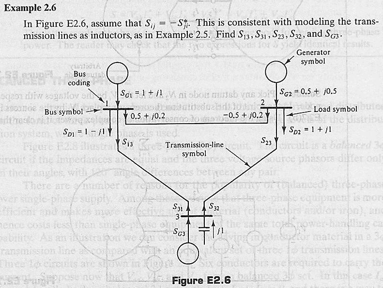
28 Example.5 Determine the real and reactive powers supplied or received by each source and the power loss in the line S 1 =P 1 +jq 1 S 1 =P 1 +jq 1 I 1 V = 10 5 V, V = V, Z = 1 + j7 Ω 1 I I = = A 1+ j = = A 1+ j P S = VI = = 97.5 W + j363.3 var * S = VI = = W j94.5 var * S = S1 + S1 = 9.8 W + j68.8 var = P + jq PL QL L L L = RI1 = (1)(3.135) = 9.8 W = X I1 = (7)(3.135) = 68.8 var P, Watts P L P Source #1 Voltage Phase Angle, δ 1
29 Balanced Three-Phase Circuits A balanced source: three sinusoidal voltages are generated having the same amplitude but displaced in phase by 10 o Instantaneous power delivered to the external loads is constant Positive phase sequence Negative phase sequence 9
30 Balanced Y-connected Loads EAn = Ep α A EBn = Ep α A 10 ECn = Ep α A 40 VAn = EAn ZG Ia Van = VAn ZLIa Let V an be the reference: Phase voltages (line-to-neutral voltages): V an = V 0 V V 10 p bn = V V 40 p cn = p Line voltages (line-to-line voltages): V = V V = V ( ) = 3 V 30 ab an bn p p V = V V = V ( ) = 3 V 90 bc bn cn p p V = V V = V ( ) = 3 V 150 ca cn an p p 30 V = 3V L V bc p
 The balanced 3-phase power system problems can be solved on a per-phase basis, e.g. for Phase A only. The other two phases carry identical currents except for phase shifts.")
31 I I a I b c Van Van 0 = = = Ip θ Z Z θ p p Vbn = = Ip 10 θ Z p Vcn = = Ip 40 θ Z p I L = I p On the neutral line (return line) I n =I a +I b +I c =0 The neutral line may not actually exist (one line per phase) The balanced 3-phase power system problems can be solved on a per-phase basis, e.g. for Phase A only. The other two phases carry identical currents except for phase shifts. 31
32 Balanced -connected Loads V L = V p Let I ab be the reference: I I ab bc I ca = I 0 p = I 10 p = I 40 p I = I I = I ( ) = 3 I 30 a ab ca p p I = I I = I ( ) = 3 I 150 b bc ab p p I = I I = I ( ) = 3 I 90 c ca bc p p I = 3 L I p 3
33 -Y Transformation Idea: compare I a =f (V an, Z ) and I a =f Y (V an, Z Y ) Z Z n Find I a =f (V an, Z ): Z I a V V V + V = + = Z Z Z ab ac ab ac I a = 3V an Z V ca Find I a =f Y (V an, Z ): I a = V Z an Y V + V = 3 V V 30 ab ac an an = 3 V ( 3/ + j/+ 3/ j/) = 3V an an Z Y = Z 3 33
34 Balanced Three-Phase Power v = V cos( ωt+ θ ) an p v v = V cos( ωt+ θ 10 ) bn p v v = V cos( ωt+ θ 40 ) cn p v For balanced loads i = I cos( ωt+ θ ) an p i i = I cos( ωt+ θ 10 ) bn p i i = I cos( ωt+ θ 40 ) cn p i Total instantaneous power: p = 3 vani + a vbni + φ b vcnic = V I cos( ωt+ θ )cos( ωt+ θ ) p p v i + V I cos( ωt+ θ 10 ) cos( ωt+ θ 10 ) p p v i + V I cos( ωt+ θ 40 ) cos( ωt+ θ 40 ) p p v i p3 φ = Vp Ip [cos( θv θi) + cos( ωt+ θv + θi)] + V I [cos( θ θ ) + cos(ωt+ θ + θ 40 )] p p v i v i + V I [cos( θ θ ) + cos(ωt+ θ + θ 480 )] p p v i v i Zero Total instantaneous power is constant: p3 = P3 = 3 Vp Ip cos φ φ θ Where is reactive power? 34
35 Extend the concept of complex power to 3-phase systems Q3 φ = 3 Vp Ip sinθ S = P + jq = V I * 3φ 3φ 3φ 3 p p Expressed in terms of line voltage V L and line current I L Y-connection: V = V / 3 Ip = IL -connection: p V p L = V I = I / 3 L p L P3 φ = 3 VL IL cosθ Q3 φ = 3 VL IL cosθ θ is the angle between the phase voltage and the phase current for the same phase (e.g. Phase A) 35
36 Example.7 (a) (b) (c) (d) The current, real power and reactive powers drawn from the supply The line voltage at the combined loads The current per phase in each load The total real and reactive powers in each load and the line 36
37 V =110-j0 37
38 Homework #3 Read through Saadat s Chapter.5~.1 ECE51:.7~.10,.14~.16 ECE41:.7,.8,.10,.15,.16 Due date: 9/0 (Friday) submitted in class or by 38
ECE 421/521 Electric Energy Systems Power Systems Analysis I 2 Basic Principles. Instructor: Kai Sun Fall 2014
 ECE 41/51 Electric Energy Systems Power Systems Analysis I Basic Princiles Instructor: Kai Sun Fall 014 1 Outline Power in a 1-hase AC circuit Comlex ower Balanced 3-hase circuit Single Phase AC System
BASIC PRINCIPLES. Power In Single-Phase AC Circuit
 BASIC PRINCIPLES Power In Single-Phase AC Circuit Let instantaneous voltage be v(t)=v m cos(ωt+θ v ) Let instantaneous current be i(t)=i m cos(ωt+θ i ) The instantaneous p(t) delivered to the load is p(t)=v(t)i(t)=v
Lecture 11 - AC Power
 - AC Power 11/17/2015 Reading: Chapter 11 1 Outline Instantaneous power Complex power Average (real) power Reactive power Apparent power Maximum power transfer Power factor correction 2 Power in AC Circuits
AC Power Analysis. Chapter Objectives:
 AC Power Analysis Chapter Objectives: Know the difference between instantaneous power and average power Learn the AC version of maximum power transfer theorem Learn about the concepts of effective or value
Sinusoidal Steady State Analysis (AC Analysis) Part II
 Part II") Sinusoidal Steady State Analysis (AC Analysis) Part II Amin Electronics and Electrical Communications Engineering Department (EECE) Cairo University elc.n102.eng@gmail.com http://scholar.cu.edu.eg/refky/
Sinusoidal Steady State Analysis (AC Analysis) Part II Amin Electronics and Electrical Communications Engineering Department (EECE) Cairo University elc.n102.eng@gmail.com http://scholar.cu.edu.eg/refky/
Sinusoidal Response of RLC Circuits
 Sinusoidal Response of RLC Circuits Series RL circuit Series RC circuit Series RLC circuit Parallel RL circuit Parallel RC circuit R-L Series Circuit R-L Series Circuit R-L Series Circuit Instantaneous
Three Phase Circuits
 Amin Electronics and Electrical Communications Engineering Department (EECE) Cairo University elc.n102.eng@gmail.com http://scholar.cu.edu.eg/refky/ OUTLINE Previously on ELCN102 Three Phase Circuits Balanced
11. AC Circuit Power Analysis
 . AC Circuit Power Analysis Often an integral part of circuit analysis is the determination of either power delivered or power absorbed (or both). In this chapter First, we begin by considering instantaneous
Chapter 2-3 Transformers
 Principles of Electric Machines and Power Electronics Chapter 2-3 Transformers Third Edition P. C. Sen Auto transformer Per unit system S b = S rate V b1 = V rate1 V b2 = V rate2 S b I b1 = = S rate =
Lecture 05 Power in AC circuit
 CA2627 Building Science Lecture 05 Power in AC circuit Instructor: Jiayu Chen Ph.D. Announcement 1. Makeup Midterm 2. Midterm grade Grade 25 20 15 10 5 0 10 15 20 25 30 35 40 Grade Jiayu Chen, Ph.D. 2
REACTANCE. By: Enzo Paterno Date: 03/2013
 REACTANCE REACTANCE By: Enzo Paterno Date: 03/2013 5/2007 Enzo Paterno 1 RESISTANCE - R i R (t R A resistor for all practical purposes is unaffected by the frequency of the applied sinusoidal voltage or
Lecture (5) Power Factor,threephase circuits, and Per Unit Calculations
 Power Factor,threephase circuits, and Per Unit Calculations") Lecture (5) Power Factor,threephase circuits, and Per Unit Calculations 5-1 Repeating the Example on Power Factor Correction (Given last Class) P? Q? S? Light Motor From source 1000 volts @ 60 Htz 10kW
Lecture (5) Power Factor,threephase circuits, and Per Unit Calculations 5-1 Repeating the Example on Power Factor Correction (Given last Class) P? Q? S? Light Motor From source 1000 volts @ 60 Htz 10kW
ECE 420. Review of Three Phase Circuits. Copyright by Chanan Singh, Panida Jirutitijaroen, and Hangtian Lei, For educational use only-not for sale.
 ECE 40 Review of Three Phase Circuits Outline Phasor Complex power Power factor Balanced 3Ф circuit Read Appendix A Phasors and in steady state are sinusoidal functions with constant frequency 5 0 15 10
Analysis of AC Power RMS and Phasors Power Factor. Power Factor. Eduardo Campero Littlewood
 Power Factor Eduardo Campero Littlewood Universidad Autónoma Metropolitana Azcapotzalco Campus Energy Department Content 1 Analysis of AC Power 2 RMS and Phasors 3 Power Factor Recommended Bibliography
LO 1: Three Phase Circuits
 Course: EEL 2043 Principles of Electric Machines Class Instructor: Dr. Haris M. Khalid Email: hkhalid@hct.ac.ae Webpage: www.harismkhalid.com LO 1: Three Phase Circuits Three Phase AC System Three phase
Power Factor Improvement
 Salman bin AbdulazizUniversity College of Engineering Electrical Engineering Department EE 2050Electrical Circuit Laboratory Power Factor Improvement Experiment # 4 Objectives: 1. To introduce the concept
Homework 2 SJTU233. Part A. Part B. Problem 2. Part A. Problem 1. Find the impedance Zab in the circuit seen in the figure. Suppose that R = 5 Ω.
 Homework 2 SJTU233 Problem 1 Find the impedance Zab in the circuit seen in the figure. Suppose that R = 5 Ω. Express Zab in polar form. Enter your answer using polar notation. Express argument in degrees.
Refresher course on Electrical fundamentals (Basics of A.C. Circuits) by B.M.Vyas
 by B.M.Vyas") Refresher course on Electrical fundamentals (Basics of A.C. Circuits) by B.M.Vyas A specifically designed programme for Da Afghanistan Breshna Sherkat (DABS) Afghanistan 1 Areas Covered Under this Module
Refresher course on Electrical fundamentals (Basics of A.C. Circuits) by B.M.Vyas A specifically designed programme for Da Afghanistan Breshna Sherkat (DABS) Afghanistan 1 Areas Covered Under this Module
EE313 Fall 2013 Exam #1 (100 pts) Thursday, September 26, 2013 Name. 1) [6 pts] Convert the following time-domain circuit to the RMS Phasor Domain.
![EE313 Fall 2013 Exam #1 (100 pts) Thursday, September 26, 2013 Name. 1) [6 pts] Convert the following time-domain circuit to the RMS Phasor Domain.](/thumbs/95/123488230.jpg "EE313 Fall 2013 Exam #1 (100 pts) Thursday, September 26, 2013 Name. 1) [6 pts] Convert the following time-domain circuit to the RMS Phasor Domain.") Name If you have any questions ask them. Remember to include all units on your answers (V, A, etc). Clearly indicate your answers. All angles must be in the range 0 to +180 or 0 to 180 degrees. 1) [6 pts]
Name If you have any questions ask them. Remember to include all units on your answers (V, A, etc). Clearly indicate your answers. All angles must be in the range 0 to +180 or 0 to 180 degrees. 1) [6 pts]
ELECTRIC POWER CIRCUITS BASIC CONCEPTS AND ANALYSIS
 Contents ELEC46 Power ystem Analysis Lecture ELECTRC POWER CRCUT BAC CONCEPT AND ANALY. Circuit analysis. Phasors. Power in single phase circuits 4. Three phase () circuits 5. Power in circuits 6. ingle
15-884/484 Electric Power Systems 1: DC and AC Circuits
 15-884/484 Electric Power Systems 1: DC and AC Circuits J. Zico Kolter October 8, 2013 1 Hydro Estimated U.S. Energy Use in 2010: ~98.0 Quads Lawrence Livermore National Laboratory Solar 0.11 0.01 8.44
EXP. NO. 3 Power on (resistive inductive & capacitive) load Series connection
 load Series connection") OBJECT: To examine the power distribution on (R, L, C) series circuit. APPARATUS 1-signal function generator 2- Oscilloscope, A.V.O meter 3- Resisters & inductor &capacitor THEORY the following form for
OBJECT: To examine the power distribution on (R, L, C) series circuit. APPARATUS 1-signal function generator 2- Oscilloscope, A.V.O meter 3- Resisters & inductor &capacitor THEORY the following form for
Sinusoidal Steady State Power Calculations
 10 Sinusoidal Steady State Power Calculations Assessment Problems AP 10.1 [a] V = 100/ 45 V, Therefore I = 20/15 A P = 1 (100)(20)cos[ 45 (15)] = 500W, 2 A B Q = 1000sin 60 = 866.03 VAR, B A [b] V = 100/
Toolbox: Electrical Systems Dynamics
 Toolbox: Electrical Systems Dynamics Dr. John C. Wright MIT - PSFC 05 OCT 2010 Introduction Outline Outline AC and DC power transmission Basic electric circuits Electricity and the grid Image removed due
= 32.0\cis{38.7} = j Ω. Zab = Homework 2 SJTU233. Part A. Part B. Problem 2. Part A. Problem 1
 Homework 2 SJTU233 Problem 1 Find the impedance Zab in the circuit seen in the figure. Suppose that R = 5 Ω. Express Zab in polar form. Enter your answer using polar notation. Express argument in degrees.
Revised October 6, EEL , Henry Zmuda. 2. Three-Phase Circuits 1
 Three Phase Circuitsit Revised October 6, 008. Three-Phase Circuits 1 Preliminary Comments and a quick review of phasors. We live in the time domain. We also assume a causal (nonpredictive) world. Real-world
Chapter 33. Alternating Current Circuits
 Chapter 33 Alternating Current Circuits 1 Capacitor Resistor + Q = C V = I R R I + + Inductance d I Vab = L dt AC power source The AC power source provides an alternative voltage, Notation - Lower case
12. Introduction and Chapter Objectives
 Real Analog - Circuits 1 Chapter 1: Steady-State Sinusoidal Power 1. Introduction and Chapter Objectives In this chapter we will address the issue of power transmission via sinusoidal or AC) signals. This
Sinusoidal Steady-State Analysis
 Chapter 4 Sinusoidal Steady-State Analysis In this unit, we consider circuits in which the sources are sinusoidal in nature. The review section of this unit covers most of section 9.1 9.9 of the text.
Module 4. Single-phase AC Circuits
 Module 4 Single-phase AC Circuits Lesson 14 Solution of Current in R-L-C Series Circuits In the last lesson, two points were described: 1. How to represent a sinusoidal (ac) quantity, i.e. voltage/current
Power and Energy Measurement
 Power and Energy Measurement ENE 240 Electrical and Electronic Measurement Class 11, February 4, 2009 werapon.chi@kmutt.ac.th 1 Work, Energy and Power Work is an activity of force and movement in the direction
Review of Chapter 2, Plus Matlab Examples
 Reiew of Chapter, Plus Matlab Examples. Power in single-phase circuits Let () t and () i t be defined as: () = cos ( ω + θ ) and () = cos ( ω + θ ) t V t i t I t m m i then the instantaneous power is gie
Boise State University Department of Electrical and Computer Engineering ECE 212L Circuit Analysis and Design Lab
 Objectives Boise State University Department of Electrical and Computer Engineering ECE 22L Circuit Analysis and Design Lab Experiment #4: Power Factor Correction The objectives of this laboratory experiment
Basics of Electric Circuits
 António Dente Célia de Jesus February 2014 1 Alternating Current Circuits 1.1 Using Phasors There are practical and economic reasons justifying that electrical generators produce emf with alternating and
ECE 421/521 Electric Energy Systems Power Systems Analysis I 3 Generators, Transformers and the Per-Unit System. Instructor: Kai Sun Fall 2013
 ECE 41/51 Electric Energy Systems Power Systems Analysis I 3 Generators, Transformers and the Per-Unit System Instructor: Kai Sun Fall 013 1 Outline Synchronous Generators Power Transformers The Per-Unit
1 Phasors and Alternating Currents
 Physics 4 Chapter : Alternating Current 0/5 Phasors and Alternating Currents alternating current: current that varies sinusoidally with time ac source: any device that supplies a sinusoidally varying potential
Consider a simple RC circuit. We might like to know how much power is being supplied by the source. We probably need to find the current.
 AC power Consider a simple RC circuit We might like to know how much power is being supplied by the source We probably need to find the current R 10! R 10! is VS Vmcosωt Vm 10 V f 60 Hz V m 10 V C 150
Driven RLC Circuits Challenge Problem Solutions
 Driven LC Circuits Challenge Problem Solutions Problem : Using the same circuit as in problem 6, only this time leaving the function generator on and driving below resonance, which in the following pairs
Work, Energy and Power
 1 Work, Energy and Power Work is an activity of force and movement in the direction of force (Joules) Energy is the capacity for doing work (Joules) Power is the rate of using energy (Watt) P = W / t,
Chapter 10 Objectives
 Chapter 10 Engr8 Circuit Analysis Dr Curtis Nelson Chapter 10 Objectives Understand the following AC power concepts: Instantaneous power; Average power; Root Mean Squared (RMS) value; Reactive power; Coplex
Generation, transmission and distribution, as well as power supplied to industrial and commercial customers uses a 3 phase system.
 Three-phase Circuits Generation, transmission and distribution, as well as power supplied to industrial and commercial customers uses a 3 phase system. Where 3 voltages are supplied of equal magnitude,
Power Systems - Basic Concepts and Applications - Part I
 PDHonline Course E104 (1 PDH) Power ystems Basic Concepts and Applications Part I Instructor: hihmin Hsu PhD PE 01 PDH Online PDH Center 57 Meadow Estates Drive Fairfax A 006658 Phone & Fax: 709880088
EE 3120 Electric Energy Systems Study Guide for Prerequisite Test Wednesday, Jan 18, pm, Room TBA
 EE 3120 Electric Energy Systems Study Guide for Prerequisite Test Wednesday, Jan 18, 2006 6-7 pm, Room TBA First retrieve your EE2110 final and other course papers and notes! The test will be closed book
Physics 115. AC circuits Reactances Phase relationships Evaluation. General Physics II. Session 35. R. J. Wilkes
 Session 35 Physics 115 General Physics II AC circuits Reactances Phase relationships Evaluation R. J. Wilkes Email: phy115a@u.washington.edu 06/05/14 1 Lecture Schedule Today 2 Announcements Please pick
ELG4125: Power Transmission Lines Steady State Operation
 ELG4125: Power Transmission Lines Steady State Operation Two-Port Networks and ABCD Models A transmission line can be represented by a two-port network, that is a network that can be isolated from the
Chapter 10: Sinusoidal Steady-State Analysis
 Chapter 10: Sinusoidal Steady-State Analysis 1 Objectives : sinusoidal functions Impedance use phasors to determine the forced response of a circuit subjected to sinusoidal excitation Apply techniques
EE221 - Practice for the Midterm Exam
 EE1 - Practice for the Midterm Exam 1. Consider this circuit and corresponding plot of the inductor current: Determine the values of L, R 1 and R : L = H, R 1 = Ω and R = Ω. Hint: Use the plot to determine
Power and Energy Measurement
 Power and Energy Measurement EIE 240 Electrical and Electronic Measurement April 24, 2015 1 Work, Energy and Power Work is an activity of force and movement in the direction of force (Joules) Energy is
10.1 Instantaneous Power 10.2 Average and Reactive Power 10.3 The RMS Value and Power Calculations 10.4 Complex Power
 SINUSOIDAL STEADY-STATE STATE POWER CALCULATIONS C.T. Pan 1 10.1 Instantaneous Powe 10. Aveage and Reactive Powe 10.3 The RMS Value and Powe Calculations 10.4 Complex Powe C.T. Pan 10.5 Powe Calculations
EE292: Fundamentals of ECE
 EE292: Fundamentals of ECE Fall 2012 TTh 10:00-11:15 SEB 1242 Lecture 18 121025 http://www.ee.unlv.edu/~b1morris/ee292/ 2 Outline Review RMS Values Complex Numbers Phasors Complex Impedance Circuit Analysis
THREE-PHASE CIRCUITS. Historical Profiles
 C H A P T E R THREE-PHASE CIRCUITS 1 2 Society is never prepared to receive any invention. Every new thing is resisted, and it takes years for the inventor to get people to listen to him and years more
SINUSOIDAL STEADY STATE CIRCUIT ANALYSIS
 SINUSOIDAL STEADY STATE CIRCUIT ANALYSIS 1. Introduction A sinusoidal current has the following form: where I m is the amplitude value; ω=2 πf is the angular frequency; φ is the phase shift. i (t )=I m.sin
ECE 201 Fall 2009 Final Exam
 ECE 01 Fall 009 Final Exam December 16, 009 Division 0101: Tan (11:30am) Division 001: Clark (7:30 am) Division 0301: Elliott (1:30 pm) Instructions 1. DO NOT START UNTIL TOLD TO DO SO.. Write your Name,
Sinusoidal Steady State Analysis
 Sinusoidal Steady State Analysis 9 Assessment Problems AP 9. [a] V = 70/ 40 V [b] 0 sin(000t +20 ) = 0 cos(000t 70 ).. I = 0/ 70 A [c] I =5/36.87 + 0/ 53.3 =4+j3+6 j8 =0 j5 =.8/ 26.57 A [d] sin(20,000πt
Single Phase Parallel AC Circuits
 Single Phase Parallel AC Circuits 1 Single Phase Parallel A.C. Circuits (Much of this material has come from Electrical & Electronic Principles & Technology by John Bird) n parallel a.c. circuits similar
ECE 476 Power System Analysis Fall 2014 Exam #1, Thursday, October 2, :30AM - 10:50AM
 ECE 476 Power System Analysis Fall 4 Exam #, Thursday, October, 4. 9:3AM - :5AM Name: Problem (5 p) Two balanced 3-phase loads are connected in parallel. One is Y-connected and draws 75 kw (3-phase) at.8
Lecture 3: Three-phase power circuits
 1/24/28 Lecture : Three-phase power circuits 1 nstructor: Dr. Gleb. Tcheslavski Contact: gleb@ee.lamar.edu Office Hours: TBD; Room 2 Class web site: MyLamar ntroduction 2 Almost all electric power generation
Review of Basic Electrical and Magnetic Circuit Concepts EE
 Review of Basic Electrical and Magnetic Circuit Concepts EE 442-642 Sinusoidal Linear Circuits: Instantaneous voltage, current and power, rms values Average (real) power, reactive power, apparent power,
Oscillations and Electromagnetic Waves. March 30, 2014 Chapter 31 1
 Oscillations and Electromagnetic Waves March 30, 2014 Chapter 31 1 Three Polarizers! Consider the case of unpolarized light with intensity I 0 incident on three polarizers! The first polarizer has a polarizing
Announcements: Today: more AC circuits
 Announcements: Today: more AC circuits I 0 I rms Current through a light bulb I 0 I rms I t = I 0 cos ωt I 0 Current through a LED I t = I 0 cos ωt Θ(cos ωt ) Theta function (is zero for a negative argument)
CONTENTS 1 THE POWER SYSTEM: AN OVERVIEW 1 2 BASIC PRINCIPLES 5 3 GENERATOR AND TRANSFORMER MODELS; THE PER-UNIT SYSTEM 25
 Solutions Manual Hadi Saadat Professor of Electrical Engineering Milwaukee School of Engineering Milwaukee, Wisconsin McGraw-Hill, Inc CONTENTS 1 THE POWER SYSTEM: AN OVERVIEW 1 2 BASIC PRINCIPLES 5 3
Circuit Analysis-III. Circuit Analysis-II Lecture # 3 Friday 06 th April, 18
 Circuit Analysis-III Sinusoids Example #1 ü Find the amplitude, phase, period and frequency of the sinusoid: v (t ) =12cos(50t +10 ) Signal Conversion ü From sine to cosine and vice versa. ü sin (A ± B)
Sinusoidal Steady State Analysis (AC Analysis) Part I
 Part I") Sinusoidal Steady State Analysis (AC Analysis) Part I Amin Electronics and Electrical Communications Engineering Department (EECE) Cairo University elc.n102.eng@gmail.com http://scholar.cu.edu.eg/refky/
Sinusoidal Steady State Analysis (AC Analysis) Part I Amin Electronics and Electrical Communications Engineering Department (EECE) Cairo University elc.n102.eng@gmail.com http://scholar.cu.edu.eg/refky/
ELECTROMAGNETIC OSCILLATIONS AND ALTERNATING CURRENT
 Chapter 31: ELECTROMAGNETIC OSCILLATIONS AND ALTERNATING CURRENT 1 A charged capacitor and an inductor are connected in series At time t = 0 the current is zero, but the capacitor is charged If T is the
Chapter 5 Steady-State Sinusoidal Analysis
 Chapter 5 Steady-State Sinusoidal Analysis Chapter 5 Steady-State Sinusoidal Analysis 1. Identify the frequency, angular frequency, peak value, rms value, and phase of a sinusoidal signal. 2. Solve steady-state
2 Signal Frequency and Impedances First Order Filter Circuits Resonant and Second Order Filter Circuits... 13
 Lecture Notes: 3454 Physics and Electronics Lecture ( nd Half), Year: 7 Physics Department, Faculty of Science, Chulalongkorn University //7 Contents Power in Ac Circuits Signal Frequency and Impedances
EIT Review 1. FE/EIT Review. Circuits. John A. Camara, Electrical Engineering Reference Manual, 6 th edition, Professional Publications, Inc, 2002.
 FE/EIT eview Circuits Instructor: uss Tatro eferences John A. Camara, Electrical Engineering eference Manual, 6 th edition, Professional Publications, Inc, 00. John A. Camara, Practice Problems for the
Power System Engineering Prof. Debapriya Das Department of Electrical Engineering Indian Institute of Technology, Kharagpur
 Power System Engineering Prof. Debapriya Das Department of Electrical Engineering Indian Institute of Technology, Kharagpur Lecture 41 Application of capacitors in distribution system (Contd.) (Refer Slide
RLC Circuit (3) We can then write the differential equation for charge on the capacitor. The solution of this differential equation is
 We can then write the differential equation for charge on the capacitor. The solution of this differential equation is") RLC Circuit (3) We can then write the differential equation for charge on the capacitor The solution of this differential equation is (damped harmonic oscillation!), where 25 RLC Circuit (4) If we charge
RLC Circuit (3) We can then write the differential equation for charge on the capacitor The solution of this differential equation is (damped harmonic oscillation!), where 25 RLC Circuit (4) If we charge
Chapter 15 Power And Harmonics in Nonsinusoidal Systems
 Chapter 15 Power And Harmonics in Nonsinusoidal Systems 15.1. Average power in terms of Fourier series 15.2. RMS value of a waveform 15.3. Power factor THD Distortion and Displacement factors 15.4. Power
Chapter 1W Basic Electromagnetic Concepts
 Chapter 1W Basic Electromagnetic Concepts 1W Basic Electromagnetic Concepts 1W.1 Examples and Problems on Electric Circuits 1W.2 Examples on Magnetic Concepts This chapter includes additional examples
ECE 325 Electric Energy System Components 7- Synchronous Machines. Instructor: Kai Sun Fall 2015
 ECE 325 Electric Energy System Components 7- Synchronous Machines Instructor: Kai Sun Fall 2015 1 Content (Materials are from Chapters 16-17) Synchronous Generators Synchronous Motors 2 Synchronous Generators
BASIC NETWORK ANALYSIS
 SECTION 1 BASIC NETWORK ANALYSIS A. Wayne Galli, Ph.D. Project Engineer Newport News Shipbuilding Series-Parallel dc Network Analysis......................... 1.1 Branch-Current Analysis of a dc Network......................
VTU E-LEARNING NOTES ON:
 VTU E-LEARNING NOTES ON: 10EE35 ELECTRICAL AND ELECTRONIC MEASUREMENTS AND INSTRUMENTATION BY DR. M.S. RAVIPRAKASHA PROFESSOR & HEAD DEPT. OF E&E ENGG. MALNAD COLLEGE OF ENGG. HASSAN 573 201. SUBJECT CODE
Chapter 9 Objectives
 Chapter 9 Engr8 Circuit Analysis Dr Curtis Nelson Chapter 9 Objectives Understand the concept of a phasor; Be able to transform a circuit with a sinusoidal source into the frequency domain using phasor
mywbut.com Lesson 16 Solution of Current in AC Parallel and Seriesparallel
 esson 6 Solution of urrent in Parallel and Seriesparallel ircuits n the last lesson, the following points were described:. How to compute the total impedance/admittance in series/parallel circuits?. How
Three-phase AC Circuits. Measurement of Power in a Three-phase Circuit
 Three-phase AC Circuits Lesson Measurement of Power in a Three-phase Circuit In the previous lesson, the phase and line currents for balanced delta-connected load fed from a three-phase supply, along with
Consider Figure What is the horizontal axis grid increment?
 Chapter Outline CHAPER 14 hree-phase Circuits and Power 14.1 What Is hree-phase? Why Is hree-phase Used? 14.2 hree-phase Circuits: Configurations, Conversions, Analysis 14.2.1 Delta Configuration Analysis
Work, Energy and Power
 1 Work, Energy and Power Work is an activity of force and movement in the direction of force (Joules) Energy is the capacity for doing work (Joules) Power is the rate of using energy (Watt) P = W / t,
ECE 325 Electric Energy System Components 5 Transmission Lines. Instructor: Kai Sun Fall 2015
 ECE 325 Electric Energy System Components 5 Transmission Lines Instructor: Kai Sun Fall 2015 1 Content (Materials are from Chapter 25) Overview of power lines Equivalent circuit of a line Voltage regulation
Week No. 6 Chapter Six: Power Factor Improvement
 Week No. 6 Chapter Six: Power Factor Improvement The electrical energy is almost wholly generated, transmitted and distributed in the form of alternating current. Therefore, the question of power factor
Chapter 3 AUTOMATIC VOLTAGE CONTROL
 Chapter 3 AUTOMATIC VOLTAGE CONTROL . INTRODUCTION TO EXCITATION SYSTEM The basic function of an excitation system is to provide direct current to the field winding of the synchronous generator. The excitation
PARALLEL A.C. CIRCUITS
 C H A P T E R 4 earning Objectives Solving Parallel Circuits Vector or Phasor Method Admittance Method Application of Admittance Method Complex or Phasor Algebra Series-Parallel Circuits Series Equivalent
Handout 11: AC circuit. AC generator
 Handout : AC circuit AC generator Figure compares the voltage across the directcurrent (DC) generator and that across the alternatingcurrent (AC) generator For DC generator, the voltage is constant For
Exercise Dr.-Ing. Abdalkarim Awad. Informatik 7 Rechnernetze und Kommunikationssysteme
 Exercise1 1.10.015 Informatik 7 Rechnernetze und Kommunikationssysteme Review of Phasors Goal of phasor analysis is to simplify the analysis of constant frequency ac systems v(t) = max cos(wt + q v ) i(t)
FACULTY OF ENGINEERING LAB SHEET
 FCLTY F ENGNEERNG LB SHEET EEL1196 nstrumentation & Measurement Techniques TRMESTER 2 2017-2018 M2: Power Measurement sing Two Wattmeter Method *Note: Students will have to tabulate the theoretical values
04-Electric Power. ECEGR 452 Renewable Energy Systems
 04-Electric Power ECEGR 452 Renewable Energy Systems Overview Review of Electric Circuits Phasor Representation Electrical Power Power Factor Dr. Louie 2 Introduction Majority of the electrical energy
Sinusoidal Steady-State Analysis
 Sinusoidal Steady-State Analysis Almost all electrical systems, whether signal or power, operate with alternating currents and voltages. We have seen that when any circuit is disturbed (switched on or
ECE Spring 2015 Final Exam
 ECE 20100 Spring 2015 Final Exam May 7, 2015 Section (circle below) Jung (1:30) 0001 Qi (12:30) 0002 Peleato (9:30) 0004 Allen (10:30) 0005 Zhu (4:30) 0006 Name PUID Instructions 1. DO NOT START UNTIL
Sinusoidal Steady-State Analysis
 Sinusoidal Steady-State Analysis Mauro Forti October 27, 2018 Constitutive Relations in the Frequency Domain Consider a network with independent voltage and current sources at the same angular frequency
Course Updates. Reminders: 1) Assignment #10 due Today. 2) Quiz # 5 Friday (Chap 29, 30) 3) Start AC Circuits
 Assignment #10 due Today. 2) Quiz # 5 Friday (Chap 29, 30) 3) Start AC Circuits") ourse Updates http://www.phys.hawaii.edu/~varner/phys272-spr10/physics272.html eminders: 1) Assignment #10 due Today 2) Quiz # 5 Friday (hap 29, 30) 3) Start A ircuits Alternating urrents (hap 31) In this
ourse Updates http://www.phys.hawaii.edu/~varner/phys272-spr10/physics272.html eminders: 1) Assignment #10 due Today 2) Quiz # 5 Friday (hap 29, 30) 3) Start A ircuits Alternating urrents (hap 31) In this
Electronic Power Conversion
 Electronic Power Conversion Review of Basic Electrical and Magnetic Circuit Concepts Challenge the future 3. Review of Basic Electrical and Magnetic Circuit Concepts Notation Electric circuits Steady state
Lecture 2 Introduction
 EE 333 POWER SYSTEMS ENGNEERNG Lecture 2 ntroduction Dr. Lei Wu Departent of Electrical and Coputer Engineering Clarkson University Resilient Underground Microgrid in Potsda, NY Funded by NYSERDAR + National
AC Electric Machines. Objectives. Introduction. 1. To understand what the meant by the term ac circuit. 2. To understand how to analyze ac circuits.
 AC Electric Machines Objectives 1. To understand what the meant by the term ac circuit.. To understand how to analyze ac circuits. 3. To understand the basic construction and operation of an ac machine.
Basics of Network Theory (Part-I)
") Basics of Network Theory (Part-I) 1. One coulomb charge is equal to the charge on (a) 6.24 x 10 18 electrons (b) 6.24 x 10 24 electrons (c) 6.24 x 10 18 atoms (d) none of the above 2. The correct relation
Basics of Network Theory (Part-I) 1. One coulomb charge is equal to the charge on (a) 6.24 x 10 18 electrons (b) 6.24 x 10 24 electrons (c) 6.24 x 10 18 atoms (d) none of the above 2. The correct relation
Three Phase Systems 295
 Three Phase Systems 95 9. MEASUEMENT OF POE Star-Connected Balanced Load with Neutral Point Power can be measured in this case by connecting a single wattmeter with its current coil in one line and the
Sinusoids and Phasors
 CHAPTER 9 Sinusoids and Phasors We now begins the analysis of circuits in which the voltage or current sources are time-varying. In this chapter, we are particularly interested in sinusoidally time-varying
a + b Time Domain i(τ)dτ.
dτ.") R, C, and L Elements and their v and i relationships We deal with three essential elements in circuit analysis: Resistance R Capacitance C Inductance L Their v and i relationships are summarized below.
R, C, and L Elements and their v and i relationships We deal with three essential elements in circuit analysis: Resistance R Capacitance C Inductance L Their v and i relationships are summarized below.
Chapter 10: Sinusoids and Phasors
 Chapter 10: Sinusoids and Phasors 1. Motivation 2. Sinusoid Features 3. Phasors 4. Phasor Relationships for Circuit Elements 5. Impedance and Admittance 6. Kirchhoff s Laws in the Frequency Domain 7. Impedance
Review of DC Electric Circuit. DC Electric Circuits Examples (source:
 Review of DC Electric Circuit DC Electric Circuits Examples (source: http://hyperphysics.phyastr.gsu.edu/hbase/electric/dcex.html) 1 Review - DC Electric Circuit Multisim Circuit Simulation DC Circuit