LO 1: Three Phase Circuits
|
|
|
- Sheryl Lynch
- 5 years ago
- Views:
Transcription
1 Course: EEL 2043 Principles of Electric Machines Class Instructor: Dr. Haris M. Khalid Webpage: LO 1: Three Phase Circuits
2 Three Phase AC System Three phase is generated by a generator with three sets of independent windings which are physically spaced 120 degrees around the stator. oltages are labeled phase a, phase b, and phase c and have the same magnitude but differ in phase angle by 120 degrees. 5
3 Three Phase AC System 6
4 Three Phase AC System 7

5 Three Phase AC System The waveform of a three-phase ac generator 8
6 Three Phase AC System Three-phase systems have either three or four conductors. There are three-phase conductors identified as A, B, and C. The three phases are 120 degrees out of phase with each other (360 divided by 3). There is sometimes a fourth conductor, which is the neutral. 9


7 Three Phase AC System The abc (or positive) phase sequence 10


8 Three Phase AC System The acb (or negative) phase sequence 11
9 Three Phase AC System The two basic connections of ac three-phase source Y-connected source Δ-connected source 12

10 Three Phase AC System 13
11 Three Phase AC System Why use 3-phase? 3-phase motors, generators, and transformers are more efficient Smooth torque on generator shaft Delivery of constant power to a 3-phase load 3 or 4 Wires and not 6 Can deliver more power for a given weight and cost oltage regulation is better 14
12 Three Phase AC System Why use 3-phase? The horsepower rating of three-phase motors and the ka rating of three-phase transformers are 150% greater than single-phase motors or transformers of similar frame size. 15

13 Three Phase AC System Why use 3-phase? The power delivered by a single-phase system pulsates and falls to zero. The three-phase power never falls to zero. The power delivered to the load in a three-phase system is the same at any instant. This produces superior operating characteristics for three-phase motors. 16
14 Three Phase AC System Why use 3-phase? A three-phase system needs three conductors; however, each conductor is only 75% the size of the equivalent ka rated single-phase conductors. 17
15 Three-Phase Systems Relationship between the phases in a threephase arrangement 18
16 Three-Phase Systems Three-phase arrangements may use either 3 or 4 conductors 19
17 Three Phase AC System Ia ab a b ac Ib Ic bc 20
18 Star/Delta Connections 21
19 Two Common Methods Three-phase Connection phase voltage (a) Y-connected sources (b) -connected sources 22
20 Star Connection The wye, or star, connection is made by connecting one end of each of the phase windings together in a common node. Each phase winding has a voltage drop known as the phase voltage. The line voltage is measured from phase conductor to a different phase conductor. 23
21 Star Connection The line voltage is higher than the phase voltage by a factor of the square root of 3 (1.732) 3 L p The line current is equal to the phase current I L I p 24
22 Star Connection I L I p I L I p p L 3 L p I p I p I L L I L 25

23 Star Connection ector sum of typical wye system voltages 26
24 Phase and Line oltages The line-to-line voltage ab of the Y-connected source ab a b p ( 0.5 j0.866) p p 3 30 p p Similarly bc ca 3 90 p p 27
25 The Y-to-Y Circuit A four-wire Y-to-Y circuit 28
26 Four - wire InN IaA IbB IcC The average power delivered by the three-phase source to the three-phase load P PA PB PC 29
27 When Z A = Z B = Z C the load is said to be balanced 30
28 There is no current in the wire connecting the neutral node of the source to the neutral node of the load. InN IaA IbB IcC 0 The average power delivered to the load is: P P P P A B C cos( ) cos( ) cos( ) Z Z Z 2 3 cos( ) Z 31
29 The Y-to-Y Circuit (3-wire) A three-wire Y-to-Y circuit 32
30 Y-Y Three - wire 0 I aa I bb I cc We need to solve for Nn IaA, IbB, and IcC Z Z Z a Nn b Nn c Nn A B C 0 Z Z Z a Nn b Nn c Nn A B C Z Z Z Nn Nn Nn A B C Solve for Nn Nn ( 120 ) Z Z 120 Z Z 0Z Z Z Z Z Z Z Z A C A B B C A C A B B C 33
31 When the circuit is balanced i.e. Z A = Z B = Z C Nn ( 120 ) ZZ 120ZZ 0ZZ ZZ ZZ ZZ 0 The average power delivered to the load is: or P P P P A B C 2 3 cos( ) Z P 3 I cos Q 3 I sin, S 3 I *, 34
32 Transmission lines A three-wire Y-to-Y circuit with line impedances 35
33 The analysis of balanced Y-Y circuits is simpler than the analysis of unbalanced Y-Y circuits. Nn = 0. It is not necessary to solve for Nn. The line currents have equal magnitudes and differ in phase by 120 degree. Equal power is absorbed by each impedance. Per-phase equivalent circuit 36
34 Delta Connection The line current is higher than the phase current by a factor of the square root of 3 (1.732) I 3 L I P The line current is equal to the phase current L P 37
35 Delta Connection I L L P p L I p I p I L I p I L I 3 L I P 38
36 The -Connected Source and Load ab bc ca 1200 rms rms rms Circulating current I ( ab bc ca ) A Unacceptable Total resistance around the loop Therefore the sources connection is seldom used in practice. 39
37 Z A The -Y and Y- Transformation Z C ZB Z Z Z A B C ZZ 1 3 Z Z Z ZZ 2 3 Z Z Z Z ZZ 1 2 Z Z Z 1 Z 3 Z 2 Z Z Z Z Z Z Z Z Z Z A B B C A C Z Z Z Z Z Z Z B A B B C A C Z Z Z Z Z Z Z A A B B C A C C 40
38 The Y- Circuits I I I aa AB CA I I I bb BC AB I I I cc CA BC where I I I AB BC CA Z Z AB 3 BC 1 CA Z2 41
39 The Y- Circuits (cont.) I I I or aa AB CA I cos jsin I cos( 120 ) jsin( 120 ) 3 I( 30 ) I 3 I I 3I aa L p 42
40 The Balanced Three-Phase Circuits Y-to- circuit equivalent Y-to-Y circuit Z Y Z 3 per-phase equivalent circuit 43
41 Instantaneous and Average Power The total average power delivered to the balanced Y-connected load is I I, aa L AI AN P A Phase A 44
42 Instantaneous and Average Power in Balanced Three Phase Circuits The total average power delivered to the balanced -connected load is P P 3P 3 I cos AB AB AB 3 P I cos P P 3 L I cos L 45
43 Active and Reactive Power When a circuit has resistive and reactive parts, the resultant power has 2 parts: The first is dissipated in the resistive element. This is the active power, P The second is stored and returned by the reactive element. This is the reactive power, Q, which has units of volt amperes reactive or var While reactive power is not dissipated it does have an effect on the system for example, it increases the current that must be supplied and increases losses with cables 46
44 Active and Reactive Power Consider an RL circuit the relationship between the various forms of power can be illustrated using a power triangle 47
45 Three Phase Power Single phase power P I cos In a balanced 3 phase system the total power is equal to three times the power in any one phase P 3 P I cos P In star and delta, 3 phase power can also be calculated using this formula P 3 L I cos L Note that this is the same on wye or delta systems 48
46 Active and Reactive Power For Single Phase: Active Power P I cos watts Reactive Power Q I sin var Apparent Power S I * A S 2 = P 2 + Q 2 49
47 Active and Reactive Power For 3-Phase: Active Power P 3 P I cos P watts Reactive Power Q 3 P I sin P var Apparent Power S * 3 P IP A S 2 = P 2 + Q 2 50
48 Active and Reactive Power For 3-Phase: Active Power P 3 L I cos L watts Reactive Power Q 3 L I sin L var Apparent Power S * 3 L IL A S 2 = P 2 + Q 2 51
49 Power Measurement When using AC, power is determined not only by the r.m.s. values of the voltage and current, but also by the phase angle (which determines the power factor) consequently, you cannot determine the power from independent measurements of current and voltage 52
50 Power Measurement In single-phase systems power is normally measured using a watt-meter measures power directly using a single meter which effectively multiplies instantaneous current and voltage 53
 a single wattmeter can be used, its reading being multiplied by 3 to get the total")
51 Power Measurement In three-phase systems we need to sum the power taken from the various phases in a four-wire system it may be necessary to use 3 single-phase watt-meters in balanced systems (systems that take equal power from each phase) a single wattmeter can be used, its reading being multiplied by 3 to get the total power 54
52 Power Measurement In three-wire arrangements we can deduce the total power from measurements using 2 single-phase wattmeters The watt-meters are supplied by the line current and the line-to-line voltage. The total power is the algebraic sum of the two watt-meters reading. 55
53 Two-Wattmeter Power Measurement cc = current coil vc = voltage coil W1 read 1 AB A cos 1 P I W2 read P I cos 2 CB C 2 For balanced load with abc phase sequence 30 and 30 1 a 2 a is the angle between phase current and phase voltage of phase a a 56
54 Two-Wattmeter Power Measurement (cont.) P P P 1 2 2I cos cos 30 L L 3I cos L L To determine the power factor angle P1 P2 LI L2cos cos30 P1 P2 LI L( 2sin sin 30 ) P1 P2 LI L2cos cos30 3 P P I ( 2sin sin 30 ) tan 1 2 L L P1 P2 1 P1 P 2 tan 3 or tan 3 P1 P2 P1 P2 57

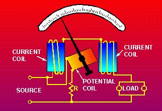
55 Power Measurement Some wattmeters, such as those used on switchboards, are specially designed to give a direct read out of the 3-phase power. The Figure shows a megawatt-range wattmeter circuit that measures the power in a generating station. The current transformers (CT) and potential transformers (PT) step down the line currents and voltages to values compatible with the instrument rating. 58
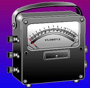
56 Electrodynamic Wattmeter 59


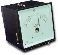
57 Digital Power Meter AR Meter pf Meter 60
58 ARmeter A ARmeter indicates the reactive power in a circuit. It is built the same way as a wattmeter is, but an internal circuit shifts the line voltage by 90 before it is applied to the potential coil. ARmeters are mainly employed in the control rooms of generating stations and the substations of electrical utilities and large industrial consumers. 61
59 ARmeter In 3-phase, 3-wire balanced circuits, we can calculate the reactive power from the two wattmeter readings by simply multiplying the difference of the two readings by 3. For example, if the two wattmeters indicate W and W respectively, the reactive power is ( ) 3 = 6176 AR. Note that this method of AR measurement is only valid for balanced 3-phase circuits. 62
60 Example 1 A balanced star connected 3 phase load of 10Ω per phase is supplied from a Hz mains supply at unity power factor Calculate the phase voltage, the line current and the total power consumed 63
61 Example 1 A balanced star connected 3 phase load of 10Ω per phase is supplied from a Hz mains supply at unity power factor Calculate the phase voltage, the line current and the total power consumed I L I p 3 L p P L P
62 Example 1 A balanced star connected 3 phase load of 10Ω per phase is supplied from a Hz mains supply at unity power factor Calculate the phase voltage, the line current and the total power consumed I I L I p I R I L I P R 230 I 23A L P 10 P P 65
63 Example 1 A balanced star connected 3 phase load of 10Ω per phase is supplied from a Hz mains supply at unity power factor Calculate the phase voltage, the line current and the total power consumed P 3 L I cos P kW L 66
64 Example 2 A 20 kw 400 balanced delta connected load has a power factor of 0.8 Calculate the line current and the phase current 67
65 Example 2 A 20 kw 400 balanced delta connected load has a power factor of 0.8 Calculate the line current and the phase current I P L I L 3 L I cos P 3 cos L L 20000( w) I L 36A 68
66 Example 2 A 20 kw 400 balanced delta connected load has a power factor of 0.8 Calculate the line current and the phase current I L 36A Delta connection therefore I I 3 L I P P I L 3 I P 36 3 I P A 69
67 Example 3 A 3Ph, 60 Hz wye connected generator generates a line to-line voltage of 23,900. Calculate a. The line-to-neutral voltage b. The voltage induced in the individual windings c. The time interval between the positive peak voltage of phase A and the positive peak of phase B d. The peak value of the line voltage 70
68 Example 3 A 3Ph, 60 Hz wye connected generator generates a line to-line voltage of 23,900. Calculate a. The line-to-neutral voltage b. The voltage induced in the individual windings c. The time interval between the positive peak voltage of phase A and the positive peak of phase B d. The peak value of the line voltage (a) The line-to-neutral voltage is: E p =E L / 3 = 23,900 / 3 = 13,800 (b) The windings are connected in wye, consequently, the voltage induced in each winding is 13,800. (c) One complete cycle (360 ) corresponds to 1/60 s. Consequently, a phase angle of 120 corresponds to an interval of T = 120 / 360 x 1/ 60 = 5.55 ms (d) The peak line voltage is: E l(peak) = 2 E L = 23,900 2 = 33,800 71
69 Example 4 The generator in the Figure generates a line voltage of 865, and each load resistor has an impedance of 50 Ω. Calculate a. The voltage across each resistor b. The current in each resistor c. The total power output of the generator 72
70 Example 4 The generator in the Figure generates a line voltage of 865, and each load resistor has an impedance of 50 Ω. Calculate a. The voltage across each resistor b. The current in each resistor c. The total power output of the generator (a) The voltage across each resistor is: E p =E L / 3 = 865 / 3 = 500 (b) The current in each resistor is: I p = E p / R = 500 / 50 = 10 A All the line currents are equal to10 A. (c) Power absorbed by each resistor is: P = E p I p = 500 x 10 = 5000 W The power delivered by the generator to all three resistors is: P = =15 kw 73
71 Example 5 Three identical impedances are connected in delta across a 3- phase, 550 line. If the line current is 10 A, calculate the following: a. The current in each impedance b. The value of each impedance 74
72 Example 5 Three identical impedances are connected in delta across a 3- phase, 550 line. If the line current is 10 A, calculate the following: a. The current in each impedance b. The value of each impedance (a) The current in each impedance is: I z = 10 / 3 = 5.77 A (b) The voltage across each impedance is 550. Consequently: Z = E / I z = 550 / 5.77 = 95 Ω 75
73 Example 6 A 3-phase motor, connected to a 440 line, draws a line current of 5 A. If the power factor of the motor is 80 percent, calculate the following: a. The total apparent power b. The total active power c. The total reactive power absorbed by the machine 76
74 Example 7 Three identical resistors dissipating a total power of 3000 W are connected in wye across a 3- phase, 550 line. Calculate: a. The current in each line b. The value of each resistor c. In Figure shown, the phase sequence of the source is known to be A-C-B. Draw the phasor diagram of the line voltages. 77
75 Example 7 Three identical resistors dissipating a total power of 3000 W are connected in wye across a 3-phase, 550 line. Calculate: a. The current in each line b. The value of each resistor (a) The power dissipated by each resistor is: P = 3000 W/3 =1000 W The voltage across the terminals of each resistor is: E =550 / 3 =318 The current in each resistor is: I = P/E =1000 W / 318 = 3.15 A The current in each line is also 3.15 A. (b) The resistance of each element is: R = E / I = 318 / 3.15 =101 Ω 78
76 Example 7 Three identical resistors dissipating a total power of 3000 W are connected in wye across a 3- phase, 550 line. Calculate: c. In Figure shown, the phase sequence of the source is known to be A-C-B. Draw the phasor diagram of the line voltages. (c) The voltages follow the sequence A-C-B, which is the same as the sequence AC-CB-BA-AC... Consequently, the line voltage sequence is E AC -E CB - E BA and the corresponding phasor diagram is shown. We can reverse the phase sequence of a 3-phase line by interchanging any two conductors. 79
77 Example 8 In the circuit shown, calculate the following: a. The current in each line b. The voltage across the inductor terminals 80
78 Example 8 In the circuit shown, calculate the following: a. The current in each line b. The voltage across the inductor terminals (a) Each branch is composed of an inductive reactance X L =4 Ω in series with a resistance R=3 Ω. Therefore, the impedance of each branch is Z p = 5 Ω. The voltage across each branch is: E p = E L / 3 = 440 / 3 = 254 The current in each circuit element is: I p = E p / Z p = 254 / 5 = 50.8 A (b) The voltage across each inductor is: E = I X L = 50.8 x 4 =
79 Example 9 A 3-phase, 550, 60 Hz line is connected to three identical capacitors connected in delta. If the line current is 22 A, calculate the capacitance of each capacitor. 82
80 Example 9 A 3-phase, 550, 60 Hz line is connected to three identical capacitors connected in delta. If the line current is 22 A, calculate the capacitance of each capacitor. (a) The current in each capacitor is: I p = I L / 3 = 22 A / 3 = 12.7 A oltage across each capacitor is: E p = 550 Capacitive reactance X c of each capacitor is: X c = E p / I p =550/12.7 =43.3Ω. (a) The capacitance of each capacitor is: C = 1 / (2 ᴫ f X c ) = 61.3 µf 83
81 Example 10 A manufacturing plant draws a total of 415 ka from a 2400 (line-to-line), 3-phase line. If the plant power factor is 87.5 percent lagging, calculate: a. The impedance of the plant, per phase b. The phase angle between the lineto-neutral voltage and the line current c. The complete phasor diagram for the plant 84
82 Example 10 A manufacturing plant draws a total of 415 ka from a 2,400 (line-to-line), 3-phase line. If the plant power factor is 87.5 percent lagging, calculate: a. The impedance of the plant, per phase b. The phase angle between the lineto-neutral voltage and the line current c. The complete phasor diagram for the plant (a) We assume a wye connection composed of three identical impedances Z. The voltage per branch is: E p = 2,400 / 3 = 1,386 The current per branch is: I p = S / (3 E p ) I p = 415,000 / (3 x 1,386) = 100 A The impedance per branch is: Z = E p / I p = 1,386 / 100 = 13.9 Ω (b) The phase angle between the line-toneutral voltage (1386 ) and the corresponding line current (100 A) is given by: cos = = 29 The current in each phase lags 29 behind the line-to-neutral voltage. 85
83 Example 11 A 5000 hp, wye-connected motor is connected to a 4000, 3-phase, 60 Hz line. A delta-connected capacitor bank rated at 1800 kvar is also connected to the line. If the motor produces an output of 3594 hp at an efficiency of 93% and a power factor of 90% (lagging), calculate the following: a. The active power absorbed by the motor b. The reactive power absorbed by the motor c. The reactive power supplied by the transmission line d. The apparent power supplied by the transmission line e. The transmission line current f. The motor line current g. Draw the complete phasor diagram for one phase 86
84 Example 11 A 5000 hp, wye-connected motor is connected to a 4000, 3-phase, 60 Hz line. A delta-connected capacitor bank rated at 1800 kvar is also connected to the line. If the motor produces an output of 3594 hp at an efficiency of 93% and a power factor of 90% (lagging), calculate the following: a. The active power absorbed by the motor b. The reactive power absorbed by the motor c. The reactive power supplied by the transmission line d. The apparent power supplied by the transmission line e. The transmission line current f. The motor line current g. Draw the complete phasor diagram for one phase (a) Active power output is: P 2 =3594 hp =2681 kw Active power input to motor: P m = P 2 / η = 2681 / 0.93 = 2883 kw (b) Apparent power absorbed by the motor: S m = P m / cos = 2883 / 0.90 = 3203 ka Reactive power absorbed by the motor: Q m = (S m 2 - P m 2 ) = 1395 kvar 87
85 Example 11 A 5000 hp, wye-connected motor is connected to a 4000, 3-phase, 60 Hz line. A delta-connected capacitor bank rated at 1800 kvar is also connected to the line. If the motor produces an output of 3594 hp at an efficiency of 93% and a power factor of 90% (lagging), calculate the following: a. The active power absorbed by the motor b. The reactive power absorbed by the motor c. The reactive power supplied by the transmission line d. The apparent power supplied by the transmission line e. The transmission line current f. The motor line current g. Draw the complete phasor diagram for one phase (c) Reactive power supplied by the capacitor bank: Q c = kvar Total reactive power absorbed by the load: Q L = Q c + Q m = = -405 kvar This is an unusual situation because reactive power is being returned to the line. In most cases the capacitor bank furnishes no more than Q m kilovars of reactive power. (d) Active power supplied by the line is P L = P m =2883 kw Apparent power supplied by the line is: S L = (P L 2 + Q L 2 ) = 2911 ka 88
86 Example 11 A 5000 hp, wye-connected motor is connected to a 4000, 3-phase, 60 Hz line. A delta-connected capacitor bank rated at 1800 kvar is also connected to the line. If the motor produces an output of 3594 hp at an efficiency of 93% and a power factor of 90% (lagging), calculate the following: a. The active power absorbed by the motor b. The reactive power absorbed by the motor c. The reactive power supplied by the transmission line d. The apparent power supplied by the transmission line e. The transmission line current f. The motor line current g. Draw the complete phasor diagram for one phase (e) Transmission line current is: I L = S L / (E L x 3) = 420 A (f) Motor line current is: I m = S m / (E L x 3) = 462 A (g) The line-to-neutral voltage is E p = 4000/ 3 = 2309 Phase angle between the motor current and the line-to-neutral voltage is: cos = 0.9 = 25.8 (The motor current lags 25.8 behind the voltage, as shown in the phasor diagram.) Line current drawn by the capacitor bank is: I c = Q c / (E L x 3) = / (4000 x 3) = 260 A 89
87 Example 11 A 5000 hp, wye-connected motor is connected to a 4000, 3-phase, 60 Hz line. A delta-connected capacitor bank rated at 1800 kvar is also connected to the line. If the motor produces an output of 3594 hp at an efficiency of 93% and a power factor of 90% (lagging), calculate the following: a. The active power absorbed by the motor b. The reactive power absorbed by the motor c. The reactive power supplied by the transmission line d. The apparent power supplied by the transmission line e. The transmission line current f. The motor line current g. Draw the complete phasor diagram for one phase 90
88 Example #12 Calculate the total apparent power for three-phase Y-Y connected balanced system shown if the phase voltage is 110, and load impedance per phase is Ω. a b c 1100 rms rms rms 91
89 S 3 I * A Repeat the last example, if the source voltage is 230 (rms) and the load impedance is Ω? 92
90 Example #13 Calculate the total apparent power for three-phase 4-wire Y-Y connected shown in if the phase voltage is 110, and load impedances are: Z 50 j80 Z Z A B C j j25 a b c 1100 rms rms rms 93
91 Unbalanced 4-wire S S I 68 j109 A * A aa a I * B bb b * C cc c j242 A S I 114 j28 A S S S S A A B C j 94
92 Example #14 Calculate the total apparent power for three-phase 3-wire Y-Y connected shown if the phase voltage is 110, and load impedances are: Z 50 j80 Z Z A B C j j25 95
93 Nn ( ) Z Z Z Z 1100Z Z Z Z Z Z Z Z A C A B B C rms A C A B B C IaA, IbB, and IcC Z Z Z a Nn b Nn c Nn A B C S I I ( I Z ) 146 j234 A * * A aa a aa aa A S I I ( I Z ) j94 A * * B bb b bb bb B S I I ( I Z ) 141 j35 A * * C cc c cc cc C S S S S A A B C j 96
94 Example #15 Calculate the total source real power, the total power delivered to the load, and the total power loss in the transmission line for threephase 3-wire Y-Y connected shown in the Figure. 97
95 98 50) ( ) ( j j Z Z I A load Line a aa watt I P I v aa a a ) ( cos watt P P a T 3
96 P Load A I aa 2 Real ( Z LA ) watt P Total Load 3P Load A watt P Total Line loss 3P Lineloss A watt 99
97 Example -16 I P =? I L =? a b rms rms c The -connected load is balanced with Z 1050 AB I AB 2250 A 2200 Z AB a b rms BC b c CA c a The line currents are rms rms I I BC CA rms rms BC A Z CA A Z I I I , I , I aa AB CA bb cc rms 100 rms
98 Example - 17 I P =? Z Z L a b c 1100 rms j5 75 j225 rms rms Z Y Z 25 j75 3 I aa a A rms Z Z L Y 101
99 I bb A and I A rms The voltages in the per-phase equivalent circuit are rms rms cc I Z AN aa Y BN CN The line-to-line voltages are AB AN BN rms BC BN CN CA CN AN rms rms I I I AB BC CA rms rms AB A Z BC A Z CA A Z rms rms rms 102
100 Example 18 P =? Z Z L a b c 1100 rms j5 75 j225 I aa rms rms a A rms Z Z L Y I Z rms AN aa Y P 3(99.6)(1.26)cos(5 ( 66 )) W 103
101 Example 19 P =? Z 1045 line-to-line voltage = 220rms The phase voltage The line current 220 A 30 3 I A A Z and I B P I 1 AC A 1 P I 2 BC B 2 cos 2698 W cos 723 W P P1 P W 104
102 Example 20 A full-load test on a 10 hp, 3-phase motor yields the following results: P 1 = + 5,950 W; P 2 = + 2,380 W; the current in each of the three lines is 10 A; and the line voltage is 600. Calculate the power factor of the motor. 105
103 Example 20 A full-load test on a 10 hp, 3-phase motor yields the following results: P 1 = + 5,950 W; P 2 = + 2,380 W; the current in each of the three lines is 10 A; and the line voltage is 600. Calculate the power factor of the motor. Apparent power supplied to the motor is: S L = 3 x E L x I L = = 3 x 600 x 10 = 10,390 A Active power supplied to the motor is: P = 5, ,380 = 8,330 W P.F. = cos = P / S = 8,330 / 10,390 = 0.80, or 80% 106
104 Example 21 When the motor in the previous example runs at no-load, the line current drops to 3.6 A and the wattmeter readings are P 1 = W; P 2 = -845 W. Calculate the no-load losses and power factor. 107
105 Example 21 When the motor in the previous example runs at no-load, the line current drops to 3.6 A and the wattmeter readings are P 1 = W; P 2 = -845 W. Calculate the no-load losses and power factor. Apparent power supplied to the motor is: S L = 3 x E L x I L = = 3 x 600 x 3.6 = 3,741 A No-load losses are: P = P 1 + P 2 = 1, = 450 W P.F. = cos = P / S = 450 / 3741 = 0.12 = 12% 108
ECE 420. Review of Three Phase Circuits. Copyright by Chanan Singh, Panida Jirutitijaroen, and Hangtian Lei, For educational use only-not for sale.
 ECE 40 Review of Three Phase Circuits Outline Phasor Complex power Power factor Balanced 3Ф circuit Read Appendix A Phasors and in steady state are sinusoidal functions with constant frequency 5 0 15 10
UNIT- I Phase Sequence:
 UNIT- I Phase Sequence: Phase sequence refers to the relation between voltages (or currents, as well) in a three-phase system. The common representation of this relation is in terms of a phasor diagram,
Sinusoidal Response of RLC Circuits
 Sinusoidal Response of RLC Circuits Series RL circuit Series RC circuit Series RLC circuit Parallel RL circuit Parallel RC circuit R-L Series Circuit R-L Series Circuit R-L Series Circuit Instantaneous
Three Phase Circuits
 Amin Electronics and Electrical Communications Engineering Department (EECE) Cairo University elc.n102.eng@gmail.com http://scholar.cu.edu.eg/refky/ OUTLINE Previously on ELCN102 Three Phase Circuits Balanced
ENE 104 Electric Circuit Theory
 Electric Circuit Theory Lecture 11: : Dejwoot KHAWPARSUTH http://webstaff.kmutt.ac.th/~dejwoot.kha/ Objectives : Ch12 Page 2 single-phase and polyphase systems Y- and Δ- connected three-phase system per-phase
THREE PHASE SYSTEMS Part 1
 ERT105: ELECTRCAL TECHNOLOGY CHAPTER 3 THREE PHASE SYSTEMS Part 1 1 Objectives Become familiar with the operation of a three phase generator and the magnitude and phase relationship. Be able to calculate
Power Factor Improvement
 Salman bin AbdulazizUniversity College of Engineering Electrical Engineering Department EE 2050Electrical Circuit Laboratory Power Factor Improvement Experiment # 4 Objectives: 1. To introduce the concept
Unit-3. Question Bank
 Unit- Question Bank Q.1 A delta connected load draw a current of 15A at lagging P.F. of.85 from 400, -hase, 50Hz suly. Find & of each hase. Given P = = 400 0 I = 15A Ans. 4.98, 5.7mH So I P = 15 =8.66A
Lecture (5) Power Factor,threephase circuits, and Per Unit Calculations
 Power Factor,threephase circuits, and Per Unit Calculations") Lecture (5) Power Factor,threephase circuits, and Per Unit Calculations 5-1 Repeating the Example on Power Factor Correction (Given last Class) P? Q? S? Light Motor From source 1000 volts @ 60 Htz 10kW
Lecture (5) Power Factor,threephase circuits, and Per Unit Calculations 5-1 Repeating the Example on Power Factor Correction (Given last Class) P? Q? S? Light Motor From source 1000 volts @ 60 Htz 10kW
VTU E-LEARNING NOTES ON:
 VTU E-LEARNING NOTES ON: 10EE35 ELECTRICAL AND ELECTRONIC MEASUREMENTS AND INSTRUMENTATION BY DR. M.S. RAVIPRAKASHA PROFESSOR & HEAD DEPT. OF E&E ENGG. MALNAD COLLEGE OF ENGG. HASSAN 573 201. SUBJECT CODE
Power and Energy Measurement
 Power and Energy Measurement EIE 240 Electrical and Electronic Measurement April 24, 2015 1 Work, Energy and Power Work is an activity of force and movement in the direction of force (Joules) Energy is
Three Phase Systems 295
 Three Phase Systems 95 9. MEASUEMENT OF POE Star-Connected Balanced Load with Neutral Point Power can be measured in this case by connecting a single wattmeter with its current coil in one line and the
Lecture 11 - AC Power
 - AC Power 11/17/2015 Reading: Chapter 11 1 Outline Instantaneous power Complex power Average (real) power Reactive power Apparent power Maximum power transfer Power factor correction 2 Power in AC Circuits
Power Systems - Basic Concepts and Applications - Part I
 PDHonline Course E104 (1 PDH) Power ystems Basic Concepts and Applications Part I Instructor: hihmin Hsu PhD PE 01 PDH Online PDH Center 57 Meadow Estates Drive Fairfax A 006658 Phone & Fax: 709880088
AC Power Analysis. Chapter Objectives:
 AC Power Analysis Chapter Objectives: Know the difference between instantaneous power and average power Learn the AC version of maximum power transfer theorem Learn about the concepts of effective or value
FACULTY OF ENGINEERING LAB SHEET
 FCLTY F ENGNEERNG LB SHEET EEL1196 nstrumentation & Measurement Techniques TRMESTER 2 2017-2018 M2: Power Measurement sing Two Wattmeter Method *Note: Students will have to tabulate the theoretical values
Generation, transmission and distribution, as well as power supplied to industrial and commercial customers uses a 3 phase system.
 Three-phase Circuits Generation, transmission and distribution, as well as power supplied to industrial and commercial customers uses a 3 phase system. Where 3 voltages are supplied of equal magnitude,
THREE-PHASE CIRCUITS. Historical Profiles
 C H A P T E R THREE-PHASE CIRCUITS 1 2 Society is never prepared to receive any invention. Every new thing is resisted, and it takes years for the inventor to get people to listen to him and years more
Three-phase AC Circuits. Measurement of Power in a Three-phase Circuit
 Three-phase AC Circuits Lesson Measurement of Power in a Three-phase Circuit In the previous lesson, the phase and line currents for balanced delta-connected load fed from a three-phase supply, along with
Sinusoidal Steady State Analysis (AC Analysis) Part II
 Part II") Sinusoidal Steady State Analysis (AC Analysis) Part II Amin Electronics and Electrical Communications Engineering Department (EECE) Cairo University elc.n102.eng@gmail.com http://scholar.cu.edu.eg/refky/
Sinusoidal Steady State Analysis (AC Analysis) Part II Amin Electronics and Electrical Communications Engineering Department (EECE) Cairo University elc.n102.eng@gmail.com http://scholar.cu.edu.eg/refky/
Chapter 2-3 Transformers
 Principles of Electric Machines and Power Electronics Chapter 2-3 Transformers Third Edition P. C. Sen Auto transformer Per unit system S b = S rate V b1 = V rate1 V b2 = V rate2 S b I b1 = = S rate =
Work, Energy and Power
 1 Work, Energy and Power Work is an activity of force and movement in the direction of force (Joules) Energy is the capacity for doing work (Joules) Power is the rate of using energy (Watt) P = W / t,
12. Introduction and Chapter Objectives
 Real Analog - Circuits 1 Chapter 1: Steady-State Sinusoidal Power 1. Introduction and Chapter Objectives In this chapter we will address the issue of power transmission via sinusoidal or AC) signals. This
BASIC NETWORK ANALYSIS
 SECTION 1 BASIC NETWORK ANALYSIS A. Wayne Galli, Ph.D. Project Engineer Newport News Shipbuilding Series-Parallel dc Network Analysis......................... 1.1 Branch-Current Analysis of a dc Network......................
Power and Energy Measurement
 Power and Energy Measurement ENE 240 Electrical and Electronic Measurement Class 11, February 4, 2009 werapon.chi@kmutt.ac.th 1 Work, Energy and Power Work is an activity of force and movement in the direction
Basics of Electric Circuits
 António Dente Célia de Jesus February 2014 1 Alternating Current Circuits 1.1 Using Phasors There are practical and economic reasons justifying that electrical generators produce emf with alternating and
Exercise Dr.-Ing. Abdalkarim Awad. Informatik 7 Rechnernetze und Kommunikationssysteme
 Exercise1 1.10.015 Informatik 7 Rechnernetze und Kommunikationssysteme Review of Phasors Goal of phasor analysis is to simplify the analysis of constant frequency ac systems v(t) = max cos(wt + q v ) i(t)
EE 3120 Electric Energy Systems Study Guide for Prerequisite Test Wednesday, Jan 18, pm, Room TBA
 EE 3120 Electric Energy Systems Study Guide for Prerequisite Test Wednesday, Jan 18, 2006 6-7 pm, Room TBA First retrieve your EE2110 final and other course papers and notes! The test will be closed book
SSC-JE EE POWER SYSTEMS: GENERATION, TRANSMISSION & DISTRIBUTION SSC-JE STAFF SELECTION COMMISSION ELECTRICAL ENGINEERING STUDY MATERIAL
 1 SSC-JE STAFF SELECTION COMMISSION ELECTRICAL ENGINEERING STUDY MATERIAL Power Systems: Generation, Transmission and Distribution Power Systems: Generation, Transmission and Distribution Power Systems:
ELECTRIC POWER CIRCUITS BASIC CONCEPTS AND ANALYSIS
 Contents ELEC46 Power ystem Analysis Lecture ELECTRC POWER CRCUT BAC CONCEPT AND ANALY. Circuit analysis. Phasors. Power in single phase circuits 4. Three phase () circuits 5. Power in circuits 6. ingle
University of Jordan Faculty of Engineering & Technology Electric Power Engineering Department
 University of Jordan Faculty of Engineering & Technology Electric Power Engineering Department EE471: Electrical Machines-II Tutorial # 2: 3-ph Induction Motor/Generator Question #1 A 100 hp, 60-Hz, three-phase
THREE-PHASE CIRCUITS
 THR-HAS CIRCUITS 4.1 Introduction Generation, Transmission and distribution of electricity via the National Grid system is accomplished by three-phase alternating currents. The voltage induced by a single
11. AC Circuit Power Analysis
 . AC Circuit Power Analysis Often an integral part of circuit analysis is the determination of either power delivered or power absorbed (or both). In this chapter First, we begin by considering instantaneous
BASIC PRINCIPLES. Power In Single-Phase AC Circuit
 BASIC PRINCIPLES Power In Single-Phase AC Circuit Let instantaneous voltage be v(t)=v m cos(ωt+θ v ) Let instantaneous current be i(t)=i m cos(ωt+θ i ) The instantaneous p(t) delivered to the load is p(t)=v(t)i(t)=v
Pre-Lab. Introduction
 Pre-Lab Read through this entire lab. Perform all of your calculations (calculated values) prior to making the required circuit measurements. You may need to measure circuit component values to obtain
Lecture 05 Power in AC circuit
 CA2627 Building Science Lecture 05 Power in AC circuit Instructor: Jiayu Chen Ph.D. Announcement 1. Makeup Midterm 2. Midterm grade Grade 25 20 15 10 5 0 10 15 20 25 30 35 40 Grade Jiayu Chen, Ph.D. 2
mywbut.com Lesson 16 Solution of Current in AC Parallel and Seriesparallel
 esson 6 Solution of urrent in Parallel and Seriesparallel ircuits n the last lesson, the following points were described:. How to compute the total impedance/admittance in series/parallel circuits?. How
Single Phase Parallel AC Circuits
 Single Phase Parallel AC Circuits 1 Single Phase Parallel A.C. Circuits (Much of this material has come from Electrical & Electronic Principles & Technology by John Bird) n parallel a.c. circuits similar
Electrical Machines-I Prof. D. Kastha Department of Electrical Engineering Indian Institute of Technology, Kharagpur
 Electrical Machines-I Prof. D. Kastha Department of Electrical Engineering Indian Institute of Technology, Kharagpur Lecture - 20 Potential and Current Transformers (Refer Slide Time: 00:37) So far we
PARALLEL A.C. CIRCUITS
 C H A P T E R 4 earning Objectives Solving Parallel Circuits Vector or Phasor Method Admittance Method Application of Admittance Method Complex or Phasor Algebra Series-Parallel Circuits Series Equivalent
PESIT Bangalore South Campus Hosur road, 1km before Electronic City, Bengaluru -100 Department of Electronics & Communication Engineering
 QUESTION PAPER INTERNAL ASSESSMENT TEST 2 Date : /10/2016 Marks: 0 Subject & Code: BASIC ELECTRICAL ENGINEERING -15ELE15 Sec : F,G,H,I,J,K Name of faculty : Dhanashree Bhate, Hema B, Prashanth V Time :
Refresher course on Electrical fundamentals (Basics of A.C. Circuits) by B.M.Vyas
 by B.M.Vyas") Refresher course on Electrical fundamentals (Basics of A.C. Circuits) by B.M.Vyas A specifically designed programme for Da Afghanistan Breshna Sherkat (DABS) Afghanistan 1 Areas Covered Under this Module
Refresher course on Electrical fundamentals (Basics of A.C. Circuits) by B.M.Vyas A specifically designed programme for Da Afghanistan Breshna Sherkat (DABS) Afghanistan 1 Areas Covered Under this Module
ECE 421/521 Electric Energy Systems Power Systems Analysis I 2 Basic Principles. Instructor: Kai Sun Fall 2013
 ECE 41/51 Electric Energy Systems Power Systems Analysis I Basic Principles Instructor: Kai Sun Fall 013 1 Outline Power in a 1-phase AC circuit Complex power Balanced 3-phase circuit Single Phase AC System
Electric Circuits II Power Measurement. Dr. Firas Obeidat
 Electric Circuits II Power Measurement Dr. Firas Obeidat 1 Table of contents 1 Single-Phase Power Measurement 2 Three-Phase Power Measurement 2 Single-Phase Power Measurement The wattmeter is the instrument
Homework 2 SJTU233. Part A. Part B. Problem 2. Part A. Problem 1. Find the impedance Zab in the circuit seen in the figure. Suppose that R = 5 Ω.
 Homework 2 SJTU233 Problem 1 Find the impedance Zab in the circuit seen in the figure. Suppose that R = 5 Ω. Express Zab in polar form. Enter your answer using polar notation. Express argument in degrees.
= 32.0\cis{38.7} = j Ω. Zab = Homework 2 SJTU233. Part A. Part B. Problem 2. Part A. Problem 1
 Homework 2 SJTU233 Problem 1 Find the impedance Zab in the circuit seen in the figure. Suppose that R = 5 Ω. Express Zab in polar form. Enter your answer using polar notation. Express argument in degrees.
EEE3405 ELECTRICAL ENGINEERING PRINCIPLES 2 - TEST
 ATTEMPT ALL QUESTIONS (EACH QUESTION 20 Marks, FULL MAKS = 60) Given v 1 = 100 sin(100πt+π/6) (i) Find the MS, period and the frequency of v 1 (ii) If v 2 =75sin(100πt-π/10) find V 1, V 2, 2V 1 -V 2 (phasor)
Circuit Analysis-II. Circuit Analysis-II Lecture # 5 Monday 23 rd April, 18
 Circuit Analysis-II Capacitors in AC Circuits Introduction ü The instantaneous capacitor current is equal to the capacitance times the instantaneous rate of change of the voltage across the capacitor.
Alternating Current Circuits
 Alternating Current Circuits AC Circuit An AC circuit consists of a combination of circuit elements and an AC generator or source. The output of an AC generator is sinusoidal and varies with time according
EXP. NO. 3 Power on (resistive inductive & capacitive) load Series connection
 load Series connection") OBJECT: To examine the power distribution on (R, L, C) series circuit. APPARATUS 1-signal function generator 2- Oscilloscope, A.V.O meter 3- Resisters & inductor &capacitor THEORY the following form for
OBJECT: To examine the power distribution on (R, L, C) series circuit. APPARATUS 1-signal function generator 2- Oscilloscope, A.V.O meter 3- Resisters & inductor &capacitor THEORY the following form for
Work, Energy and Power
 1 Work, Energy and Power Work is an activity of force and movement in the direction of force (Joules) Energy is the capacity for doing work (Joules) Power is the rate of using energy (Watt) P = W / t,
Module 4. Single-phase AC circuits. Version 2 EE IIT, Kharagpur
 Module 4 Single-phase circuits ersion EE T, Kharagpur esson 6 Solution of urrent in Parallel and Seriesparallel ircuits ersion EE T, Kharagpur n the last lesson, the following points were described:. How
Lecture 3: Three-phase power circuits
 1/24/28 Lecture : Three-phase power circuits 1 nstructor: Dr. Gleb. Tcheslavski Contact: gleb@ee.lamar.edu Office Hours: TBD; Room 2 Class web site: MyLamar ntroduction 2 Almost all electric power generation
ELECTROMAGNETIC OSCILLATIONS AND ALTERNATING CURRENT
 Chapter 31: ELECTROMAGNETIC OSCILLATIONS AND ALTERNATING CURRENT 1 A charged capacitor and an inductor are connected in series At time t = 0 the current is zero, but the capacitor is charged If T is the
Consider Figure What is the horizontal axis grid increment?
 Chapter Outline CHAPER 14 hree-phase Circuits and Power 14.1 What Is hree-phase? Why Is hree-phase Used? 14.2 hree-phase Circuits: Configurations, Conversions, Analysis 14.2.1 Delta Configuration Analysis
Review of Basic Electrical and Magnetic Circuit Concepts EE
 Review of Basic Electrical and Magnetic Circuit Concepts EE 442-642 Sinusoidal Linear Circuits: Instantaneous voltage, current and power, rms values Average (real) power, reactive power, apparent power,
Ch 8. Three-phase systems
 Ch 8. Three-ase systems Lecture outcomes (what you are supposed to learn): Generation of three-ase voltages Connection of three-ase circuits Wye-Delta transformation Power of three-ase connected loads
Total No. of Questions :09] [Total No. of Pages : 03
![Total No. of Questions :09] [Total No. of Pages : 03](/thumbs/94/118747664.jpg "Total No. of Questions :09] [Total No. of Pages : 03") EE 4 (RR) Total No. of Questions :09] [Total No. of Pages : 03 II/IV B.Tech. DEGREE EXAMINATIONS, APRIL/MAY- 016 Second Semester ELECTRICAL & ELECTRONICS NETWORK ANALYSIS Time: Three Hours Answer Question
EE 4 (RR) Total No. of Questions :09] [Total No. of Pages : 03 II/IV B.Tech. DEGREE EXAMINATIONS, APRIL/MAY- 016 Second Semester ELECTRICAL & ELECTRONICS NETWORK ANALYSIS Time: Three Hours Answer Question
Consider a simple RC circuit. We might like to know how much power is being supplied by the source. We probably need to find the current.
 AC power Consider a simple RC circuit We might like to know how much power is being supplied by the source We probably need to find the current R 10! R 10! is VS Vmcosωt Vm 10 V f 60 Hz V m 10 V C 150
Power System Analysis Prof. A. K. Sinha Department of Electrical Engineering Indian Institute of Technology, Kharagpur
 Power System Analysis Prof. A. K. Sinha Department of Electrical Engineering Indian Institute of Technology, Kharagpur Lecture - 9 Transmission Line Steady State Operation Welcome to lesson 9, in Power
Week No. 6 Chapter Six: Power Factor Improvement
 Week No. 6 Chapter Six: Power Factor Improvement The electrical energy is almost wholly generated, transmitted and distributed in the form of alternating current. Therefore, the question of power factor
CHAPTER 22 ELECTROMAGNETIC INDUCTION
 CHAPTER 22 ELECTROMAGNETIC INDUCTION PROBLEMS 47. REASONING AND Using Equation 22.7, we find emf 2 M I or M ( emf 2 ) t ( 0.2 V) ( 0.4 s) t I (.6 A) ( 3.4 A) 9.3 0 3 H 49. SSM REASONING AND From the results
Chapter 1W Basic Electromagnetic Concepts
 Chapter 1W Basic Electromagnetic Concepts 1W Basic Electromagnetic Concepts 1W.1 Examples and Problems on Electric Circuits 1W.2 Examples on Magnetic Concepts This chapter includes additional examples
Review of DC Electric Circuit. DC Electric Circuits Examples (source:
 Review of DC Electric Circuit DC Electric Circuits Examples (source: http://hyperphysics.phyastr.gsu.edu/hbase/electric/dcex.html) 1 Review - DC Electric Circuit Multisim Circuit Simulation DC Circuit
Chapter 33. Alternating Current Circuits
 Chapter 33 Alternating Current Circuits 1 Capacitor Resistor + Q = C V = I R R I + + Inductance d I Vab = L dt AC power source The AC power source provides an alternative voltage, Notation - Lower case
ECE 476 Power System Analysis Fall 2014 Exam #1, Thursday, October 2, :30AM - 10:50AM
 ECE 476 Power System Analysis Fall 4 Exam #, Thursday, October, 4. 9:3AM - :5AM Name: Problem (5 p) Two balanced 3-phase loads are connected in parallel. One is Y-connected and draws 75 kw (3-phase) at.8
Power Systems - Basic Concepts and Applications - Part I
 PDHonline Course E104A (1 PDH) Power Systems - Basic Concepts and Applications - Part I Instructor: Shih-Min Hsu, Ph.D., P.E. 01 PDH Online PDH Center 57 Meadow Estates Drive Fairfax, VA 030-6658 Phone
KINGS COLLEGE OF ENGINEERING Punalkulam
 KINGS COLLEGE OF ENGINEERING Punalkulam 613 303 DEPARTMENT OF ELECTRICAL AND ELECTRONICS ENGINEERING POWER SYSTEM ANALYSIS QUESTION BANK UNIT I THE POWER SYSTEM AN OVERVIEW AND MODELLING PART A (TWO MARK
Brief Steady of Power Factor Improvement
 International Journal of Electrical Engineering. ISSN 0974-2158 Volume 6, Number 5 (2013), pp. 531-539 International Research PublicationHouse http://www.irphouse.com Brief Steady of Power Factor Improvement
EE313 Fall 2013 Exam #1 (100 pts) Thursday, September 26, 2013 Name. 1) [6 pts] Convert the following time-domain circuit to the RMS Phasor Domain.
![EE313 Fall 2013 Exam #1 (100 pts) Thursday, September 26, 2013 Name. 1) [6 pts] Convert the following time-domain circuit to the RMS Phasor Domain.](/thumbs/95/123488230.jpg "EE313 Fall 2013 Exam #1 (100 pts) Thursday, September 26, 2013 Name. 1) [6 pts] Convert the following time-domain circuit to the RMS Phasor Domain.") Name If you have any questions ask them. Remember to include all units on your answers (V, A, etc). Clearly indicate your answers. All angles must be in the range 0 to +180 or 0 to 180 degrees. 1) [6 pts]
Name If you have any questions ask them. Remember to include all units on your answers (V, A, etc). Clearly indicate your answers. All angles must be in the range 0 to +180 or 0 to 180 degrees. 1) [6 pts]
Conventional Paper-I Part A. 1. (a) Define intrinsic wave impedance for a medium and derive the equation for intrinsic vy
 Define intrinsic wave impedance for a medium and derive the equation for intrinsic vy") EE-Conventional Paper-I IES-01 www.gateforum.com Conventional Paper-I-01 Part A 1. (a) Define intrinsic wave impedance for a medium and derive the equation for intrinsic vy impedance for a lossy dielectric
EE-Conventional Paper-I IES-01 www.gateforum.com Conventional Paper-I-01 Part A 1. (a) Define intrinsic wave impedance for a medium and derive the equation for intrinsic vy impedance for a lossy dielectric
EE221 - Practice for the Midterm Exam
 EE1 - Practice for the Midterm Exam 1. Consider this circuit and corresponding plot of the inductor current: Determine the values of L, R 1 and R : L = H, R 1 = Ω and R = Ω. Hint: Use the plot to determine
Introduction to Synchronous. Machines. Kevin Gaughan
 Introduction to Synchronous Machines Kevin Gaughan The Synchronous Machine An AC machine (generator or motor) with a stator winding (usually 3 phase) generating a rotating magnetic field and a rotor carrying
MAHARASHTRA STATE BOARD OF TECHNICAL EDUCATION
 Subject Code : 17331 (ETE) Model Answer Page No : 1 of 23 Important Instructions to examiners: 1) The answers should be examined by key words and not as word-to-word as given in the model answer scheme.
Module 4. Single-phase AC Circuits
 Module 4 Single-phase AC Circuits Lesson 14 Solution of Current in R-L-C Series Circuits In the last lesson, two points were described: 1. How to represent a sinusoidal (ac) quantity, i.e. voltage/current
Revised October 6, EEL , Henry Zmuda. 2. Three-Phase Circuits 1
 Three Phase Circuitsit Revised October 6, 008. Three-Phase Circuits 1 Preliminary Comments and a quick review of phasors. We live in the time domain. We also assume a causal (nonpredictive) world. Real-world
Electrical Circuits Lab Series RC Circuit Phasor Diagram
 Electrical Circuits Lab. 0903219 Series RC Circuit Phasor Diagram - Simple steps to draw phasor diagram of a series RC circuit without memorizing: * Start with the quantity (voltage or current) that is
Electromagnetic Oscillations and Alternating Current. 1. Electromagnetic oscillations and LC circuit 2. Alternating Current 3.
 Electromagnetic Oscillations and Alternating Current 1. Electromagnetic oscillations and LC circuit 2. Alternating Current 3. RLC circuit in AC 1 RL and RC circuits RL RC Charging Discharging I = emf R
AC Circuits Homework Set
 Problem 1. In an oscillating LC circuit in which C=4.0 μf, the maximum potential difference across the capacitor during the oscillations is 1.50 V and the maximum current through the inductor is 50.0 ma.
EE Branch GATE Paper 2010
 Q.1 Q.25 carry one mark each 1. The value of the quantity P, where, is equal to 0 1 e 1/e 2. Divergence of the three-dimensional radial vector field is 3 1/r 3. The period of the signal x(t) = 8 is 0.4
coil of the circuit. [8+8]
![coil of the circuit. [8+8]](/thumbs/80/81218867.jpg "coil of the circuit. [8+8]") Code No: R05310202 Set No. 1 III B.Tech I Semester Regular Examinations, November 2008 ELECTRICAL MEASUREMENTS (Electrical & Electronic Engineering) Time: 3 hours Max Marks: 80 Answer any FIVE Questions
Code No: R05310202 Set No. 1 III B.Tech I Semester Regular Examinations, November 2008 ELECTRICAL MEASUREMENTS (Electrical & Electronic Engineering) Time: 3 hours Max Marks: 80 Answer any FIVE Questions
EE301 Three Phase Power
 Learning Objectives a. Compute the real, reactive and apparent power in three phase systems b. Calculate currents and voltages in more challenging three phase circuit arrangements c. Apply the principles
Transformer. Transformer comprises two or more windings coupled by a common magnetic circuit (M.C.).
.") . Transformers Transformer Transformer comprises two or more windings coupled by a common magnetic circuit (M.C.). f the primary side is connected to an AC voltage source v (t), an AC flux (t) will be
. Transformers Transformer Transformer comprises two or more windings coupled by a common magnetic circuit (M.C.). f the primary side is connected to an AC voltage source v (t), an AC flux (t) will be
ECE 201 Fall 2009 Final Exam
 ECE 01 Fall 009 Final Exam December 16, 009 Division 0101: Tan (11:30am) Division 001: Clark (7:30 am) Division 0301: Elliott (1:30 pm) Instructions 1. DO NOT START UNTIL TOLD TO DO SO.. Write your Name,
Lesson 17: Synchronous Machines
 Lesson 17: Synchronous Machines ET 332b Ac Motors, Generators and Power Systems Lesson 17_et332b.pptx 1 Learning Objectives After this presentation you will be able to: Explain how synchronous machines
EKT103 ELECTRICAL ENGINEERING
 EKT13 EECTRCA ENGNEERNG Chater 1 Three-Phase System 1 COURSE OUTCOME (CO) CO1: Ability to define and exlain the concet of single-hase and threehase system. 2 Revision A sinusoid is a signal that has the
Some Important Electrical Units
 Some Important Electrical Units Quantity Unit Symbol Current Charge Voltage Resistance Power Ampere Coulomb Volt Ohm Watt A C V W W These derived units are based on fundamental units from the meterkilogram-second
Chapter 32A AC Circuits. A PowerPoint Presentation by Paul E. Tippens, Professor of Physics Southern Polytechnic State University
 Chapter 32A AC Circuits A PowerPoint Presentation by Paul E. Tippens, Professor of Physics Southern Polytechnic State University 2007 Objectives: After completing this module, you should be able to: Describe
ECE 325 Electric Energy System Components 7- Synchronous Machines. Instructor: Kai Sun Fall 2015
 ECE 325 Electric Energy System Components 7- Synchronous Machines Instructor: Kai Sun Fall 2015 1 Content (Materials are from Chapters 16-17) Synchronous Generators Synchronous Motors 2 Synchronous Generators
PHYS 241 EXAM #2 November 9, 2006
 1. ( 5 points) A resistance R and a 3.9 H inductance are in series across a 60 Hz AC voltage. The voltage across the resistor is 23 V and the voltage across the inductor is 35 V. Assume that all voltages
CLUSTER LEVEL WORK SHOP
 CLUSTER LEVEL WORK SHOP SUBJECT PHYSICS QUESTION BANK (ALTERNATING CURRENT ) DATE: 0/08/06 What is the phase difference between the voltage across the inductance and capacitor in series AC circuit? Ans.
REACTANCE. By: Enzo Paterno Date: 03/2013
 REACTANCE REACTANCE By: Enzo Paterno Date: 03/2013 5/2007 Enzo Paterno 1 RESISTANCE - R i R (t R A resistor for all practical purposes is unaffected by the frequency of the applied sinusoidal voltage or
Physics 115. AC circuits Reactances Phase relationships Evaluation. General Physics II. Session 35. R. J. Wilkes
 Session 35 Physics 115 General Physics II AC circuits Reactances Phase relationships Evaluation R. J. Wilkes Email: phy115a@u.washington.edu 06/05/14 1 Lecture Schedule Today 2 Announcements Please pick
Chapter 12: Three-Phase Circuits
 Chater 1: Three-Phase Circuits 1.1 ntroduction 1. Balanced Three-Phase oltages 1.3 Balanced Wye-Wye connection 1.4 Balanced Wye-Delta Connection 1.7 Power in a Balanced System 1.1 NTRODUCTON A single-hase
Basic Electrical Engineering SYLLABUS. Total No. of Lecture Hrs. : 50 Exam Marks : 80
 SYLLABUS Subject Code: /25 No. of Lecture Hrs./ Week : 04 IA Marks : 20 Exam Hours : 03 Total No. of Lecture Hrs. : 50 Exam Marks : 80 Course objectives: Impart a basic knowledge of electrical quantities
Chapter 15 Power And Harmonics in Nonsinusoidal Systems
 Chapter 15 Power And Harmonics in Nonsinusoidal Systems 15.1. Average power in terms of Fourier series 15.2. RMS value of a waveform 15.3. Power factor THD Distortion and Displacement factors 15.4. Power
Sinusoidal Steady State Analysis (AC Analysis) Part I
 Part I") Sinusoidal Steady State Analysis (AC Analysis) Part I Amin Electronics and Electrical Communications Engineering Department (EECE) Cairo University elc.n102.eng@gmail.com http://scholar.cu.edu.eg/refky/
Sinusoidal Steady State Analysis (AC Analysis) Part I Amin Electronics and Electrical Communications Engineering Department (EECE) Cairo University elc.n102.eng@gmail.com http://scholar.cu.edu.eg/refky/
ENGR 2405 Chapter 6. Capacitors And Inductors
 ENGR 2405 Chapter 6 Capacitors And Inductors Overview This chapter will introduce two new linear circuit elements: The capacitor The inductor Unlike resistors, these elements do not dissipate energy They
FIRST TERM EXAMINATION (07 SEPT 2015) Paper - PHYSICS Class XII (SET B) Time: 3hrs. MM: 70
 Paper - PHYSICS Class XII (SET B) Time: 3hrs. MM: 70") FIRST TERM EXAMINATION (07 SEPT 205) Paper - PHYSICS Class XII (SET B) Time: 3hrs. MM: 70 Instructions:. All questions are compulsory. 2. Q.no. to 5 carry mark each. 3. Q.no. 6 to 0 carry 2 marks each.
FIRST TERM EXAMINATION (07 SEPT 205) Paper - PHYSICS Class XII (SET B) Time: 3hrs. MM: 70 Instructions:. All questions are compulsory. 2. Q.no. to 5 carry mark each. 3. Q.no. 6 to 0 carry 2 marks each.
Toolbox: Electrical Systems Dynamics
 Toolbox: Electrical Systems Dynamics Dr. John C. Wright MIT - PSFC 05 OCT 2010 Introduction Outline Outline AC and DC power transmission Basic electric circuits Electricity and the grid Image removed due