Guide to the use of the Erosion and Sediment Control Evaluation Tool
|
|
|
- Erik Stevenson
- 5 years ago
- Views:
Transcription


1 Guide to the use of the Erosion and Sediment Control Evaluation Tool December 2017 If you require content in an alternate format please contact us at or by at
2 Introduction: Early in 2017 the Lake Simcoe Region Conservation Authority (LSRCA) implemented a pilot project to develop an erosion and sedimentation control (ESC) evaluation tool and inspection form to assist with the review of compliance with current LSRCA technical guidelines within the Lake Simcoe watershed. This tool guide has been developed to assist in identifying and managing ESC risks associated with urban construction sites. The pressures of urban development have large-scale impacts on the natural environment and in particular aquatic resources and their natural corridors. Changes to land use can result in decreased permeability, increased fine sediment inputs, impact water quality and increased runoff. The changes create an imbalance in the natural processes and can lead to increased flood events, reduction in tributary baseflows, decreased natural habitat diversity and increase channel erosion. Sediment from construction activities is a major contributor to these impacts. Additional sediment from construction runoff contributes to the destabilization of watercourses that not only has extreme ecological costs, but can also result in loss of property, costly infrastructure repairs, and may require stabilization efforts which could take many years to complete. It is everyone s responsibility to prevent construction related sediment from impacting aquatic resources and other natural features. The site evaluation tool has been developed to support construction site managers, municipal inspectors and contractors at residential, commercial and major transportation related construction sites within the Lake Simcoe watershed. The following is a link to LSRCA SWM Guidelines (specific erosion and sediment control sections have been appended at the end of this document): Erosion and sedimentation control is a vital component of all construction projects including land development, building and infrastructure construction, installation of utilities or any other projects which involve the disruption of the existing or natural environments. With proper design and implementation of specific ESC measures, most impacts can be mitigated and managed to ensure downstream environments are protected from the potential damages caused by the release of sediments off site. Each construction project has its own unique issues with respect to ESC measures and typically, the designer/engineer will utilize various forms of data collection to identify topographic and natural heritage features which require protection from erosion and sedimentation. Data collection can include topographic mapping using aerial orthographic photography, in-field topographic surveys, existing mapping such as Ontario Base Mapping (OBM) or various other local information sources within the watershed. Once significant features have been identified, the designer develops detailed ESC plans in accordance with LSRCA and local area municipality guidelines to establish which specific controls and staging requirements are required to ensure that downstream natural environmental features are not impacted by any construction operations within the project limits. Typically, the designer will prepare a series of plans identifying various stages of
3 construction and how ESC measures are to be implemented throughout the entire project. As an example, on a typical land development project, topsoil stripping and earthworks may require specific ESC measures in advance of servicing operations. Once servicing is completed, different, and usually permanent, measures are constructed. Site Inspection and Evaluation Tool: Prior to any site evaluation the inspector should be completely familiar with the approved ESC engineering drawings and all LSRCA permit requirements. All significant natural heritage features should be identified including downstream watercourses, areas where runoff is most likely to be discharged and the location of sediment traps, temporary sediment ponds and future permanent stormwater management facilities where applicable. It is imperative that all sedimentation and erosion controls are in place and operational prior to the contractor removing any existing vegetative cover on site. Sediment control fencing or other approved boundary controls act as the final line of defense against sediment discharge but will not provide full protection in isolation. Properly constructed cut-off swales, rock check dams and sediment ponds or traps are critical components in any ESC plan and these must be constructed as construction is staged. The ESC evaluation tool has been created in a standard spreadsheet format and has been designed to identify various components of a typical construction project. These components are broken down into subsections to assist the inspector in clearly identifying the level of compliance with the approved ESC plans for various areas of the site. The inspector should take as many photographs of site conditions as possible during the inspection; these can be incorporated into the inspection report in a separate section (to be discussed further below). It should be noted that as with any typical site inspection report these evaluations represent a single moment in the overall progress of construction on site and may not necessarily be representative of how well or poorly a specific contractor complies with the approved drawings and permit requirements. Part 1: Site Information This section is used to provide details of the site location, LSRCA permit number (site identifier), date of inspection, specific assessment parcel identification number (APID), date of last rainfall event and amount of precipitation, etc. There are specific sections to identify the type of construction project and description of work currently underway on site; these sections have dropdown menus with various options to select from or the inspector can input others as required. There are also sections for identifying the property owner, engineering consultant, contractor and builder for the project. Part 2: Erosion and Sediment Control Inspection Results There is a scoring breakdown list included at the beginning of this section which identifies various scores for each specific component of the inspection report. Scores range from least to most critical: 0 (no issues identified), 1 (monitoring required), 2 (routine maintenance required), 3 (immediate repair/restoration required) and 4 (immediate installation of ES controls required). Within each subsection of the inspection report, there are dropdown menus
4 for specific components which incorporate the above scoring protocol; each result is colourcoded from green to red depending on the severity of the value and to visually display inspection results. Each section also has a separate area to provide additional comments; this area should be utilized by the inspector to provide specific details with respect to any subsection on the evaluation sheet. It is recommended that where details are being included, the specific cell(s) be highlighted for ease of review. Subsection 1 Site Perimeter and Adjacent lands This section is used to identify various components of the ESC requirements used to protect the site perimeter and identify any issues associated with movement of sediment off site. Obviously, this is the most critical area of the inspection report since any deficiencies are likely to cause significant downstream impacts. Where possible the inspector should traverse the entire perimeter of the site to evaluate encroachments into natural areas or adjacent lands, proper installation of perimeter sediment control fencing (single or double as specified), proper installation of construction access controls, mud tracking off site and all other specific ESC requirements identified on the approved plans. Each applicable component has a corresponding section with dropdown menu to identify the level of compliance and current condition (0 to 4) for the specific control measure. Specific attention should be placed on the condition of sediment fencing particularly in the lower areas of the site where runoff will collect before being discharged off site. Perimeter fencing (double where specified) should be stable and well constructed with no breaches. The inspector should note any areas where residue of sediment is visible on the fabric especially if the residue is evident to more than half the height of the fence; this would denote the potential for possible future failure of the fence during a significant rain event. Regardless of the current condition of any section of perimeter fencing, the inspector should always complete a visual inspection of all downstream watercourses and natural features to assess if there is any evidence of previous discharge of sediment from the site. Photographic record of any sediment discharge or other areas of concern should be taken and attached to the inspection report. Subsection 2 Internal Controls Sheet Flow Typically, on large scale projects such as subdivisions or site plans there will be significant sheet drainage patterns within the site which contribute runoff which will ultimately be directed towards the perimeter. As such, various ESC measures are employed to control the flow. Some measures include intermediate sediment fencing, maintaining existing ground cover in certain areas, use of erosion mats, straw mulch and other vegetative cover techniques designed to remove sediment, slow flow and/or protect from potential surface soil erosion. The inspector should review the existing topography of the site where sheet flow is expected to occur and evaluate all measures put in place to protect the site. One very important control is revegetation of exposed areas after topsoil stripping and earthworks operations have been completed. Within large-scale developments where lands may be left vacant for extended periods of time (such as industrial/commercial developments) it is imperative that disturbed areas be re-vegetated as soon as possible to avoid possible erosion of surface soils.
5 Some smaller sites or linear projects such as road reconstruction will not have significant or identifiable sheet drainage patterns and therefore most components in the section can be marked as not applicable (n/a). Photographs showing overall site drainage conditions should be taken for record purposes. Subsection 3 Internal Controls Concentrated flows This section deals with various ESC measures used on almost all construction projects where surface flows are being directed to temporary sediment ponds and / or traps to be treated prior to release off site. Specific control measures include cut-off swales, rock check dams (with sediment traps upstream), internal haul roads with temporary culverts, lined by-pass channels, etc. The inspector should review the measures in place to assess their effectiveness in controlling flows and removing sediments. Rock check dams should be properly constructed as per the approved standard detail with sufficient capacity in the sediment trap on the upstream side. In longer and / or steeper grade swales, a sufficient number of check dams should be installed to slow flows and allow for maximum sediment removal. The inspector should note any areas where flows appear to be overflowing or bypassing check dams where evident by bank erosion. Lined by-pass channels should be stable and show no signs of stream bank erosion which may denote insufficient capacity of the channel. Photographs should be taken to identify any areas of concern or in the case of well-constructed and properly functioning ESC measure, to show that systems are currently in place at the time of the inspection. Subsection 4 (a to d) Sediment Control Ponds The evaluation tool includes multiple sections for sediment control ponds because typically most construction sites will include more than one sediment pond or trap. The inspector can add or delete sections as required using cut-and-paste applications within the spreadsheet based on the number of sediment ponds located on a specific site. Each pond should be identified with a corresponding number and approximate location within the site for clarification. Each sediment control pond section includes various components typically found in a standard sediment pond or trap. The inspector should review the approved plans for each pond design to establish which components are incorporated into each. Where perforated risers and clear stone jackets are utilized, an assessment of the amount of sediment buildup on the clear stone should be made; excess buildup could be the result of inlet blockage or plugged filter fabric. Overflow spillways should be inspected to confirm stability and capacity. The berm enclosing the pond should also be inspected to ensure stability and that there is no evidence of significant erosion on the embankments which could eventually compromise the berm or reduce the overall storage capacity of the pond. Overall Result of Site Inspection At the end of Part 2 there is a separate section for the inspector to provide an overall rating of the site based on the overall result of the inspection. The ratings vary from A Excellent, [wherein all applicable erosion controls are in place (given rating between zero and two),
6 operating as designed and there is no evidence of sediment discharge offsite] to F Fail, [wherein the site is in poor condition, ESC measures are poorly installed/maintained and there is or may be evidence of sediment discharge from the site]. To assist the inspector with completing the site evaluation report specific criteria are identified on the evaluation sheet for each rating (grade). Part 3 Assessment of Level of Adoption of LSRCA - ESC Standards This section of the evaluation sheet includes a list of ratings for degree of compliance in the use of the most current LSRCA erosion and sedimentation control standards (copies of the specific standards and details are included at the end of this document). Compliance rating ranges from 0 ESC meet LSRCA standard to 4 Immediate installation of ESC measures required. Each standard component includes a dropdown menu for individual ratings which are also colour-coded (green to red) for visual clarification. The inspector should review all components and establish an overall rating for the site based on the worst case for each individual component. Example: if there are two temporary sediment ponds on a specific site and one of the two have significant issues associated with any component of those ponds, the rating should be reflective of the poorer constructed/maintained pond. Although this may not be totally objective it will bring attention to any issues with overall compliance. General Comments Section This section is provided for the inspector to include any specific comments, critique or any other notes regarding the overall assessment of the site. Photos and Drawings or Sketches This section has been included for the inspector to include copies or a link to any photographs taken during the inspection. Hyperlink to a separate folder is an efficient method for including multiple photos files. Copies of engineering plans, sketches, field notes or permit files can be linked in this section as well. It is suggested that any spreadsheet cells which include links be highlighted to assist the reader with visual clarification. The following pages are excerpts from the LSRCA s Technical Guidelines relating to ESC.
7 LSRCA Technical Guidelines for Stormwater Management Submissions Approval Date: June 24, 2016 Effective Date: September 1, 2016 Erosion and Sediment Control Sections 2.6 Erosion and Sediment Control Soil Erosion Soil erosion is a naturally occurring process where water picks up and transports soil particles. The degree of naturally occurring erosion will depend on a number of factors such as vegetative cover, slopes and soil type. When a site is disturbed and soil is exposed, the potential for soil erosion is greatly increased. This increase in erosion results in sediment-laden runoff, which should be considered a pollutant. This sediment-laden runoff is damaging to natural downstream systems such as wetlands, creeks, rivers and wooded-areas. As such, measures should be implemented on sites with exposed soil with the intent of: 1. Minimizing soil erosion at the source; 2. Containing sediment on site; 3. Treating sediment-laden runoff; and 4. Being proactive, not reactive. Additional benefits such as construction phase phosphorus reduction may be realized from a well-designed and well-implemented erosion and sediment control plan Erosion Control Requirements Erosion and sediment control for site alteration works must be in accordance with the Erosion and Sediment Control Guidelines for Urban Construction, 2006 and the LSRCA requirements in Appendix G. Local Municipalities may have specific additional requirements above and beyond
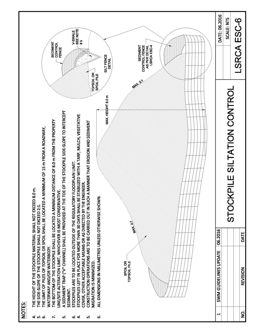
8 those outlined in the above documents, which would need to be applied to erosion and sediment control plans. As noted above in Section 2.0, Site alteration should be performed in such a manner that release of sediment into receiving waters is kept to an absolute minimum with a goal of no sediment migration offsite. In certain circumstances, this may require that the release in sediment be controlled such that natural background rates / loads are not exceeded. Key points from the LSRCA requirements for erosion and sediment control submission found in Appendix G are highlighted here: A separate erosion and sediment control plan must be included with submissions; The phasing or stages must be clear from the plans (clearing and grubbing, earthworks, restoration) and need to be itemized and shown on all ESC plans; Temporary sediment control basins or traps to be installed at low points accepting less than 2 hectares (ha) of overland drainage. The preferred sizing for temporary sediment control basin or trap is to provide a storage volume of 185m 3 /ha. At a minimum, temporary sediment basins or traps are to be sized to provide a storage volume of 125 m 3 /ha. All temporary sediment control basins or traps are to provide appropriate outlet protection; In general, temporary sediment ponds should have a contributing drainage area of no more than 10 ha. In some site-specific instances, there may be restrictions that need to be accommodated such as site outlet constraints, grading constraints and phasing. In cases where restrictions are present, intermediate controls (i.e. sediment traps used upstream of the temporary sediment pond) should be used to provide at source controls for contributing drainage areas greater than 10 ha and the temporary sediment pond would be sized for the full contributing drainage area. Temporary sediment ponds are to be sized to provide 185 m 3 /ha of permanent pool storage along with a minimum of 125m 3 /ha (in some cases 185 m 3 /ha) of active storage. Refer to Appendix G, note 4 for additional information; Swales and ditches at a minimum must be designed to convey the flow from a 5-year design storm. Municipalities may have additional requirements for swale sizing and capacity. The LSRCA may also require sizing for the flows resulting from 100 year storm as Site specific conditions dictate; Topsoil/spoil piles shall not exceed 8m in height and shall be located in such a manner as to respect the setbacks as outlined in Appendix G; and Given the importance of LIDs as part of a holistic approach to stormwater management within the LSRCA watershed, it is imperative that LIDs are not to be used for sediment control.
9
10 APPENDIX G from LSRCA Technical Guidelines EROSION AND SEDIMENT CONTROL MINIMUM REQUIREMENTS 1.0 Erosion and Sediment Control Plans, Drawings and Details This section includes the minimum requirements for erosion and sediment control plans, drawings, details, reports and supporting calculations. If there is a discrepancy between these minimum requirements and local Municipal requirements, then the more conservative requirements will apply. Typical Erosion and Sediment Control (ESC) Details sheets are included at the end of this section. 1. Identify approved development and regulatory limits on submitted plan: development limits for Site. i.e. to clarify that all works are within the development limit; floodplain elevations and floodplain limit for the 1:100 year and the regulatory event as applicable, within the area of interest. Include a reference for the modelling and mapping source; identify the meanderbelt limit and source; and any other regulatory limit as applicable, within the area of interest. 2. Separate Phase and / or Stage drawings including notes and details sheets. 3. Drawings should clearly identify the following ESC information and details as applicable: a. Contours and / or DTM points for existing and proposed elevations at each phase of construction; b. A note indicating that all sediment control measures must be installed prior to the commencement of site works; c. Notes on the inspection and maintenance of sediment controls are to be included in the ESC drawing set. Sediment controls should be inspected on a regular basis and after every significant rainfall event. Repairs to ESC measures must be completed in a timely manner to prevent sediment migration; d. Notes requiring that additional materials such as clear stone, filter fabric, pumps, hoses and siltsoxx to be kept onsite at all times for conducting repairs to sediment control measures; e. A statement is to be provided in the ESC drawing notes requiring all disturbed areas left inactive for more than thirty days are to be stabilized. Identify seed mix and / or stabilization measures within note and / or detail; f. A note must be included on the ESC drawing that engineered changes to the ESC measures may be required as Site conditions change; g. Construction access mats are to be installed at all construction entrances and exits; h. A sediment control fence detail that is consistent with the Authority standard is to be used. Heavy duty sediment control fences are to be installed downslope of all disturbed areas, see detail LSRCA ESC-4. Double row sediment control fence will be required
11 upstream of natural heritage features and as Site conditions require, see detail LSRCA ESC-5; i. Cut-off swales and ditches are to be shown as directing overland flow to the appropriate sediment trap or temporary sediment pond; j. Check dams are to be shown in all swales and ditches. Swales and ditches at a minimum must be designed to convey the flow from a 5-year design storm. Municipalities may have additional requirements for swale sizing and capacity. The LSRCA may also require sizing for the flows resulting from 100 year storm as Site specific conditions dictate; k. Temporary sediment control traps are to be shown at low points accepting less than 2 hectares (ha) of overland drainage. The preferred sizing for temporary sediment control trap is to provide a storage volume of 185m 3 / ha. At a minimum, temporary sediment traps are to be sized to provide a storage volume of 125 m 3 / ha. All temporary sediment control traps are to provide appropriate outlet protection; l. In general, temporary sediment ponds should have a contributing drainage area of no more than 10 ha. In some site-specific instances, there may be restrictions that need to be accommodated such as site outlet constraints, grading constraints and phasing. In cases where restrictions are present, intermediate controls (i.e. sediment traps used upstream of the temporary sediment pond) should be used to provide at source controls for contributing drainage areas greater than 10 ha and the temporary sediment pond would be sized for the full contributing drainage area. Refer to Note 4 below for additional clarification on temporary ESC Pond required components. Additional reference information can be found on details sheet LSRCA ESC-7; m. A general overall Site plan showing areas of cut and fill is to be provided. i.e. the typical green / red mass balance drawing is an example of this information; n. For fill within regulated areas, the volume and source of the fill are to be shown on a drawing(s). The supporting calculations are to be provided for the cut and fill analysis; o. Stockpile locations are to be shown on the drawing(s) in accordance with the following criteria: i. The height of the stockpile material shall not exceed 8.0 metres; ii. The side-slope of the stockpile shall not exceed 2:1; iii. The bottom of the stockpile shall be located a minimum distance of 15.0 metres from a municipal road, provincial road, waterway and/or a waterbody; iv. The bottom of the stockpile shall be located a minimum distance of 8.0 metres from the property-line or alteration limit, whichever is most conservative; v. Erosion control shall be provided at the base of the stockpile to intercept sediment; vi. vii. Stockpiles are to be located outside of the regulatory floodplain limit; Stockpiles left in place more than 30 days shall be stabilized with a tarp, mulch, vegetated cover, other acceptable means or as directed by the engineer; and viii. Construction operations are to be carried out in a manner that erosion and sediment migration of sediment is minimized; p. Dewatering notes and details must be identified in the ESC drawing set at the
12 appropriate ESC stage / phase, and as needed due to changing Site conditions; q. A drawing note is required identifying that the Site trailer location, equipment storage, refueling area and hydrocarbon storage are to be located outside of the regulated area limit. If the entire site falls within a regulated area, the LSRCA and municipality should be consulted to determine a suitable refuelling and storage locations. This location is to be clearly shown on the drawings; r. A note is required identifying MOECC spills action centre contact and number on ESC drawings; s. A note indicating that the contractor will be responsible for clean-up and restoration, including all costs, due to the release of sediment from the Site; t. Include proposed storm sewer alignments on appropriate phase or stage drawing; u. A sample site plan showing sediment controls to be installed during home building on individual lots (applicable to large estate residential lots only); 4. Temporary ESC Pond components identified as applicable: a. Temporary ESC ponds are to be individually sized for both the permanent pool component and active storage component based on the following requirements: For the permanent pool component, temporary ESC ponds are to be sized to provide 185 m 3 / ha of storage; and The active storage component is to be sized to provide a minimum storage of 125 m 3 / ha with a minimum 48 hour drawdown time and a minimum 4:1 length to width ratio. If the minimum 48 hour drawdown time and / or the minimum 4:1 length to width ratio cannot be met, then an active storage volume of 185 m 3 / ha will be required; b. Temporary ESC pond sized as outlined above and supported with calculations and appropriate ESC measures. i.e. as applicable outlet with orifice, emergency overflow weir, low flow outlet dispersion dam, animal protection grate, all components in details, freeboard, spot elevations, sections provided through outlet and across pond, etc.; c. Temporary ESC ponds are to have filter fabric / clear stone wrapped Hickenbottom riser outfalls (with anti-seepage collars) and rip rap (or equivalent erosion protection) overflow weirs. Reference Detail Sheet LSRCA ESC-7. The outlet must have an animal protection grate and a flow dispersion dam or suitably designed flow spreader, unless outletting directly to a storm sewer. The emergency overflow weir must be sized at a minimum to convey the 100 year event; d. Notes on the construction of the pond berms to be included on the appropriate ESC drawing (i.e. acceptable soils with low permeability to be used, 95% SPMDD compaction, inspection to be completed by a geo-technical engineer); e. Stage / storage table with supporting calculations for the temporary ESC pond is to be included in the design submission; and f. Emergency overflow weir and orifice included on drawing detail. Drawdown calculations are to be provided in the submission.
13 5. ESC details must be provided to support the ESC plan. Erosion and sediment control measures used on Site must be equal or better than the attached details. Sample details are attached and identified in the Erosion and Sediment Control Drawing Index below. 2.0 Erosion and Sediment Control Drawing Index: See following pages for the attached details. Drawing Title Erosion and Sediment Control Plan Notes Swale and Rock Check Dam Construction Access Mat Sediment Control Fence Double Row Sediment Control Fence Stockpile Siltation Control Temporary Sediment Pond and Outlet Details Drawing Number LSRCA ESC-1 LSRCA ESC-2 LSRCA ESC-3 LSRCA ESC-4 LSRCA ESC-5 LSRCA ESC-6 LSRCA ESC-7

14
15
16
17
18
19
20
Sediment Trap. A temporary runoff containment area, which promotes sedimentation prior to discharge of the runoff through a stabilized spillway.
 Sediment Trap SC-15 Source: Caltrans Construction Site Best Management Practices Manual, 2003. Description A temporary runoff containment area, which promotes sedimentation prior to discharge of the runoff
Rock & Aggregate Drop Inlet Protection
 Rock & Aggregate Drop Inlet Protection SEDIMENT CONTROL TECHNIQUE Type 1 System Sheet Flow Sandy Soils Type 2 System [1] Concentrated Flow Clayey Soils Type 3 System Supplementary Trap Dispersive Soils
B805 TEMPORARY EROSION AND SEDIMENT CONTROL MEASURES - OPSS 805
 B805 MEASURES - OPSS 805 805.1 GENERAL Construction activities frequently remove protective cover and expose soil to accelerated rates of erosion. Sediments generated thereby can be conveyed via runoff
Materials. Use materials meeting the following.
 208.01 Section 208. SOIL EROSION AND SEDIMENTATION CONTROL 208.01 Description. Install and maintain erosion and sedimentation controls to minimize soil erosion and to control sedimentation from affecting
Continuing Education Associated with Maintaining CPESC and CESSWI Certification
 Continuing Education Associated with Maintaining CPESC and CESSWI Certification Module 2: Stormwater Management Principles for Earth Disturbing Activities Sponsors: ODOTs Local Technical Assistance Program
Sediment Trap. At multiple locations within the project site where sediment control is needed.
 Sediment Trap SE-3 Objectives EC Erosion Control SE Sediment Control TR Tracking Control WE Wind Erosion Control Non-Stormwater NS Management Control Waste Management and WM Materials Pollution Control
Suitable Applications Sediment traps should be considered for use:
 Categories EC Erosion Control SE Sediment Control TC Tracking Control WE Wind Erosion Control Non-Stormwater NS Management Control Waste Management and WM Materials Pollution Control Legend: Primary Objective
FOR PROJECTS INITIATED AFTER NOVEMBER 1, 2008 ITEM 716 EMBANKMENT EARTH OUTLET SEDIMENT TRAP
 AFTER NOVEMBER 1, 2008 ITEM 716 EMBANKMENT EARTH OUTLET SEDIMENT TRAP 716.1 Description. This work shall consist of furnishing, installing, maintaining, and removing temporary erosion protection and sediment
[1] Performance of the sediment trap depends on the type of outlet structure and the settling pond surface area.
![[1] Performance of the sediment trap depends on the type of outlet structure and the settling pond surface area.](/thumbs/76/74245181.jpg "[1] Performance of the sediment trap depends on the type of outlet structure and the settling pond surface area.") Sediment Trench SEDIMENT CONTROL TECHNIQUE Type 1 System Sheet Flow Sandy Soils Type 2 System [1] Concentrated Flow Clayey Soils Type 3 System [1] Supplementary Trap Dispersive Soils [1] Performance of
Sediment Trench SEDIMENT CONTROL TECHNIQUE Type 1 System Sheet Flow Sandy Soils Type 2 System [1] Concentrated Flow Clayey Soils Type 3 System [1] Supplementary Trap Dispersive Soils [1] Performance of
Woodford County Erosion Prevention Plan and Permit. Application #
 Woodford County Erosion Prevention Plan and Permit Application # Date Instructions: Applicant will complete Parts A and B, and attach a proposed site diagram. This diagram must be completed in accordance
Specifications Whitcomb Elementary School Demolition January 15, 2016
 SECTION 31 2500 - EROSION CONTROL PART 1 - GENERAL 1.1 RELATED DOCUMENTS: A. The provisions of the Contract Documents apply to the work of this Section. B. The Virginia Erosion and Sediment Control Handbook,
Agenda. INDOT Office of Environmental Services. Describe Results of FHWA QAR. Landscape and Waterway Permitting Unit. Interviews Site Inspections
 Nathan Saxe Administrator, Ecology and Waterway Permitting Section Back to Basics: Erosion and Sediment Control FHWA INDOT Quality Assurance Review (QAR) Results 1 Agenda INDOT Office of Environmental
Stormwater Outlet Sediment Traps
 Stormwater Outlet Traps SEDIMENT CONTROL TECHNIQUES Photo 1 Excavated sediment trap just prior to scheduled clean-out (note energy dissipater at end of pipe) Photo 2 A supplementary straw bale barrier
Stone Outlet Sediment Trap
 3.12 Sediment Control Description: A stone outlet sediment trap is a small detention area formed by placing a stone embankment with an integral stone filter outlet across a drainage swale for the purpose
STREUVER FIDELCO CAPPELLI, LLC YONKERS DOWNTOWN DEVELOPMENT PHASE 1. DRAFT ENVIRONMENTAL IMPACT STATEMENT For: PALISADES POINT
 STREUVER FIDELCO CAPPELLI, LLC YONKERS DOWNTOWN DEVELOPMENT PHASE 1 DRAFT ENVIRONMENTAL IMPACT STATEMENT For: PALISADES POINT Prepared by: PAULUS, SOKOLOWSKI & SARTOR STORMWATER MANAGEMENT 1. Methodology
WELCOME Lake Wabukayne OPEN HOUSE
 WELCOME Lake Wabukayne Sediment Removal Project OPEN HOUSE We are here to: Update you, the community, on recent developments and activities at Lake Wabukayne Present the preferred alternative and receive
APPENDIX A: EROSION & SEDIMENT CONTROL FORMS
 APPENDIX A: EROSION & SEDIMENT CONTROL FORMS Croy Engineering # 1580.08 EROSION & SEDIMENT CONTROL FORMS Appendix-1 This page intentionally left blank. Croy Engineering # 1580.08 EROSION & SEDIMENT CONTROL
Instream Sediment Control Systems
 Instream Sediment Control Systems INSTREAM PRACTICES Photo 1 Photo 2 Modular sediment The information contained within this series of fact sheets deals only with the design of temporary instream sediment
Coarse Sediment Traps
 Coarse Sediment Traps SEDIMENT CONTROL TECHNIQUE Type 1 System Sheet Flow Sandy Soils Type 2 System [1] Concentrated Flow Clayey Soils [2] Type 3 System Supplementary Trap Dispersive Soils [1] Though primarily
Sediment Control Practices. John Mathews Ohio Dept. of Natural Resources, Division of Soil and Water Resources
 Sediment Control Practices John Mathews Ohio Dept. of Natural Resources, Division of Soil and Water Resources Practices Treat the Largest Soil Particles Sand Sand Silt Clay Treated Untreated Settleable
TPDES: Soil, Erosion and Sedimentation Methods
 SAWS TPDES: Soil, Erosion and Sedimentation Methods Philip Handley Supervisor-Resource Protection & Compliance August 25, 2014 TPDES: Soil, Erosion and Sedimentation Methods Soil Common term: Dirt Common
Sediment Control Log (SCL)
") Description A sediment control log is a linear roll made of natural materials such as straw, coconut fiber, or other fibrous material trenched into the ground and held with a wooden stake. Sediment control
Description A sediment control log is a linear roll made of natural materials such as straw, coconut fiber, or other fibrous material trenched into the ground and held with a wooden stake. Sediment control
MIDDLESEX COUNTY Department of Planning and Community Development P.O. Box 427, Saluda, VA Phone: Fax:
 MIDDLESEX COUNTY Department of Planning and Community Development P.O. Box 427, Saluda, VA 23149 Phone: 804-758-3382 Fax: 804-758-0061 LAND DISTURBANCE PERMIT SUBMISSION REQUIREMENTS In order to expedite
APPENDIX B WORKSHEETS & EXHIBITS
 APPENDIX B WORKSHEETS & EXHIBITS A worksheet provides the designer a representation of a measure that allows for input of specific design criteria. The plan designer will be required to assess field conditions
U-Shaped Sediment Traps
 U-Shaped Sediment Traps SEDIMENT CONTROL TECHNIQUE Type 1 System Sheet Flow Sandy Soils Type 2 System Concentrated Flow Clayey Soils [1] Type 3 System Supplementary Trap Dispersive Soils [1] Generally
Construction Exits Rock pads
 Construction Exits Rock pads SEDIMENT CONTROL TECHNIQUE Type 1 System Sheet Flow Sandy Soils Type 2 System Concentrated Flow [1] Clayey Soils Type 3 System Supplementary Trap Dispersive Soils [1] Minor
**Temporary Erosion Control**
 Construction operations And methods **Temporary Erosion Control** The test will more than likely just have a basic word problem dealing with Erosion control, if it has anything on the test. So just review,
INFLOW DESIGN FLOOD CONTROL SYSTEM PLAN 40 C.F.R. PART PLANT YATES ASH POND 2 (AP-2) GEORGIA POWER COMPANY
 GEORGIA POWER COMPANY") INFLOW DESIGN FLOOD CONTROL SYSTEM PLAN 40 C.F.R. PART 257.82 PLANT YATES ASH POND 2 (AP-2) GEORGIA POWER COMPANY EPA s Disposal of Coal Combustion Residuals from Electric Utilities Final Rule (40 C.F.R.
INFLOW DESIGN FLOOD CONTROL SYSTEM PLAN 40 C.F.R. PART 257.82 PLANT YATES ASH POND 2 (AP-2) GEORGIA POWER COMPANY EPA s Disposal of Coal Combustion Residuals from Electric Utilities Final Rule (40 C.F.R.
M. Sloat, AAg., CPESC R.J. Redden, R.P.Bio., A.Sc.T., CPESC. EDI Environmental Dynamics Inc Continental Way Prince George, B.C.
 OVERVIEW OF BEST PRACTICES FOR SURFACE EROSION PROTECTION AND SEDIMENT CONTROL FOR THE DEVELOPMENT PHASE OF SURFACE MINING FOR COAL IN NORTHEAST BRITISH COLUMBIA M. Sloat, AAg., CPESC R.J. Redden, R.P.Bio.,
Type 1 System Sheet Flow Sandy Soils Type 2 System Concentrated Flow Clayey Soils Type 3 System [1] Supplementary Trap Dispersive Soils
![Type 1 System Sheet Flow Sandy Soils Type 2 System Concentrated Flow Clayey Soils Type 3 System [1] Supplementary Trap Dispersive Soils](/thumbs/77/76519623.jpg "Type 1 System Sheet Flow Sandy Soils Type 2 System Concentrated Flow Clayey Soils Type 3 System [1] Supplementary Trap Dispersive Soils") Sediment Weirs SEDIMENT CONTROL TECHNIQUE Type 1 System Sheet Flow Sandy Soils Type 2 System Concentrated Flow Clayey Soils Type 3 System [1] Supplementary Trap Dispersive Soils [1] Type 3 classification
Sediment Weirs SEDIMENT CONTROL TECHNIQUE Type 1 System Sheet Flow Sandy Soils Type 2 System Concentrated Flow Clayey Soils Type 3 System [1] Supplementary Trap Dispersive Soils [1] Type 3 classification
Independent Environmental Audit Erosion and Sediment Control
 Independent Environmental Audit Erosion and Sediment Control Commencement of YOUNG TO BETHUNGRA LOOPING PIPELINE JUNE 2016 suite 1, 39 fitzmaurice st (po box 5464) wagga wagga nsw 2650 australia t (02)
Culvert and Pipe Phasing
 Culvert and Pipe Phasing Barney Blackburn, PE, CPESC, CPSWQ NCDOT Roadside Environmental Unit Soil & Water Engineering Section Supervisor NCDOT Culvert Phasing Process Hydraulics Unit: Culvert Survey Report
Sediment Weirs (Instream)
") Sediment Weirs (Instream) INSTREAM PRACTICES Flow Control No Channel Flow Dry Channels Erosion Control Low Channel Flows Shallow Water Sediment Control High Channel Flows [1] Deep Water [1] Sediment weirs
Sediment Weirs (Instream) INSTREAM PRACTICES Flow Control No Channel Flow Dry Channels Erosion Control Low Channel Flows Shallow Water Sediment Control High Channel Flows [1] Deep Water [1] Sediment weirs
Modeling Great Britain s Flood Defenses. Flood Defense in Great Britain. By Dr. Yizhong Qu
 Modeling Great Britain s Flood Defenses AIRCurrents Editor s note: AIR launched its Inland Flood Model for Great Britain in December 2008. The hazard module captures the physical processes of rainfall-runoff
Rock Sizing for Batter Chutes
 Rock Sizing for Batter Chutes STORMWATER MANAGEMENT PRACTICES Photo 1 Rock-lined batter chute Photo 2 Rock-lined batter chute 1. Introduction In the stormwater industry a chute is a steep drainage channel,
Template for Sediment and Erosion Control Plan General Instructions. Section Instructions
 Template for Sediment and Erosion Control Plan General Instructions Introduction: Soil erosion and sediment deposition from farmlands can contribute to degraded surface water quality. Sediment delivery
 DRAFT DRAFT DRAFT DRAFT DRAFT SEDIMENT CONTROLS Method Application Description BMP Sediment fencing Flat Ground Y Anywhere low flow runoff is Sloping Ground Y Geotextile fabric, buried at the bottom
CONSTRUCTION EXIT SEDIMENT BARRIER
 241428_itizen ield Guide_v3 2/22/06 11:09 M Page 1 (1,1) ONSTRUTION EXIT stone pad located where traffic leaves a construction site to eliminate the transport of soil to public streets. SEDIMENT BRRIER
UGRC 144 Science and Technology in Our Lives/Geohazards
 UGRC 144 Science and Technology in Our Lives/Geohazards Flood and Flood Hazards Dr. Patrick Asamoah Sakyi Department of Earth Science, UG, Legon College of Education School of Continuing and Distance Education
Gully Erosion Part 1 GULLY EROSION AND ITS CAUSES. Introduction. The mechanics of gully erosion
 Gully Erosion Part 1 GULLY EROSION AND ITS CAUSES Gully erosion A complex of processes whereby the removal of soil is characterised by incised channels in the landscape. NSW Soil Conservation Service,
EROSION AND SEDIMENT CONTROL AT CONSTRUCTION SITES GUIDELINES. City of Moncton Engineering and Environmental Services
 EROSION AND SEDIMENT CONTROL AT CONSTRUCTION SITES GUIDELINES City of Moncton Engineering and Environmental Services Revised March 2011 TABLE OF CONTENTS INTRODUCTION... 2 THE EROSION AND SEDIMENT CONTROL
Crows Landing Naval Base Easement
 1 of 15 West Stanislaus Resource Conservation District Crows Landing Naval Base Easement Annual Reserve Monitoring Report Jamie McFarlin 11/112012 2 of 15 West Stanislaus Resource Conservation District
NORTH DAKOTA DEPARTMENT OF TRANSPORTATION SPECIAL PROVISION TEMPORARY EROSION AND SEDIMENT BEST MANAGEMENT PRACTICES
 Page 1 of 5 NORTH DAKOTA DEPARTMENT OF TRANSPORTATION SPECIAL PROVISION TEMPORARY EROSION AND SEDIMENT BEST MANAGEMENT PRACTICES 1. GENERAL Install, maintain and remove appropriate Temporary Best Management
Chutes Part 5: Rock linings
 Chutes Part 5: Rock linings DRAINAGE CONTROL TECHNIQUE Low Gradient Velocity Control Short-Term Steep Gradient Channel Lining Medium-Long Term Outlet Control [1] Soil Treatment Permanent [2] [1] Chutes
Standards for Soil Erosion and Sediment Control in New Jersey May 2012
 STANDARD FOR SEDIMENT BASIN Definition A barrier, dam, excavated pit, or dugout constructed across a waterway or at other suitable locations to intercept and retain sediment. Basins created by construction
Stream Geomorphology. Leslie A. Morrissey UVM July 25, 2012
 Stream Geomorphology Leslie A. Morrissey UVM July 25, 2012 What Functions do Healthy Streams Provide? Flood mitigation Water supply Water quality Sediment storage and transport Habitat Recreation Transportation
Erosion and Sediment Control Measures 2.7 Silt Fences
 Erosion and Sediment Control Measures Silt fences are designed to intercept sheet flow sediment laden stormwater run-off and filter out both the larger and smaller particles of sediment. Silt fences and
Construction Exits Vibration grids
 Construction Exits Vibration grids SEDIMENT CONTROL TECHNIQUE Type 1 System Sheet Flow Sandy Soils Type 2 System Concentrated Flow Clayey Soils [1] Type 3 System Supplementary Trap Dispersive Soils [1]
1.0 INSPECTION ANNUAL INSPECTION, JUNE 29, 2011 CARMACKS COPPER PROJECT, CARMACKS, YUKON. Dear Mr. West-Sells,
 Doc. No. 162 Rev. 0 Mr. Paul West-Sells President & Chief Operating Officer Western Copper Corporation 2060-1111 West Georgia Street Vancouver, BC V6E 4M3 ANNUAL INSPECTION, JUNE 29, 2011 CARMACKS COPPER
Appendix E Guidance for Shallow Flooding Analyses and Mapping
 Appendix E Guidance for Shallow Flooding Analyses and Mapping E.1 Introduction Different types of shallow flooding commonly occur throughout the United States. Types of flows that result in shallow flooding
Selected Site BMPs: Why s the Water Muddy? John C. Hayes, Ph.D., P. E. Biosystems Engineering Clemson University
 Selected Site BMPs: Why s the Water Muddy? John C. Hayes, Ph.D., P. E. Biosystems Engineering Clemson University The BMP worked fine until last week when it rained! Turbidity Best Management Practices
Sediment and Erosion Control Techniques on Stream Restoration Projects
 Sediment and Erosion Control Techniques on Stream Restoration Projects D. R. Clinton, G. D. Jennings, R. A. McLaughlin, D. A. Bidelspach 1 ABSTRACT Erosion control, sediment loss and turbidity control
CHAPTER GEOLOGICALLY HAZARDOUS AREAS Applicability Regulations.
 CHAPTER 19.07 GEOLOGICALLY HAZARDOUS AREAS 19.07.010 Applicability. Geologically hazardous areas may pose a threat to the health and safety of citizens when incompatible development is sited in areas of
APPENDIX B DESIGN CRITERIA FOR TEMPORARY WATER QUALITY BMPS USED DURING CONSTRUCTION
 APPENDIX B DESIGN CRITERIA FOR TEMPORARY WATER QUALITY BMPS USED DURING CONSTRUCTION This Appendix presents design criteria and example calculations for the following temporary water quality BMPs for use
APPENDIX G APPENDIX G SEDIMENT CONTAINMENT SYSTEM DESIGN RATIONALE
 APPENDIX G SEDIMENT CONTAINMENT SYSTEM DESIGN RATIONALE March 18, 2003 This page left blank intentionally. March 18, 2003 G-2 FIGURES Page # Figure G.1 Estimated Runoff from Precipitation Over Different
ROCK EXCAVATION (GRADING) OPSS 206 INDEX
 OPSS 206 INDEX") 206-2 - OPSS 206 INDEX 206-2.1 GENERAL 206-2.1.1 Classification of Rock Materials 206-2.1.2 Tender Items 206-2.1.3 Other Excavation Tender Items 206-2.1.4 Specifications 206-2.1.5 Special Provisions 206-2.1.6
206-2 - OPSS 206 INDEX 206-2.1 GENERAL 206-2.1.1 Classification of Rock Materials 206-2.1.2 Tender Items 206-2.1.3 Other Excavation Tender Items 206-2.1.4 Specifications 206-2.1.5 Special Provisions 206-2.1.6
Stormwater Guidelines and Case Studies. CAHILL ASSOCIATES Environmental Consultants West Chester, PA (610)
") Stormwater Guidelines and Case Studies CAHILL ASSOCIATES Environmental Consultants West Chester, PA (610) 696-4150 www.thcahill.com Goals and Challenges for Manual State Stormwater Policy More Widespread
Stormwater Guidelines and Case Studies CAHILL ASSOCIATES Environmental Consultants West Chester, PA (610) 696-4150 www.thcahill.com Goals and Challenges for Manual State Stormwater Policy More Widespread
North Carolina Department of Environment and Natural Resources Division Energy, Mineral, and Land Resources Land Quality Section
 Tracy E. Davis, PE, CPM Director City of Greenville Attention: Scott Godefroy 1500 Beatty Street Greenville, NC 27834 North Carolina Department of Environment and Natural Resources Division Energy, Mineral,
Long Valley Meadow Restoration Project
 Long Valley Meadow Restoration Project USDA Forest Service Mogollon Rim Ranger District Coconino National Forest Coconino County, Arizona T13N, R9E, Section 12 and T13N, R10E, Sections 6 and 7 Gila and
Stormwater Inlet Sediment Traps
 Stormwater Inlet Sediment Traps SEDIMENT CONTROL TECHNIQUES Photo 1 Kerb inlet Photo 2 Field (drop) inlet Table 1 provides the recommended default classification of various sediment control systems suitable
Template for Sediment and Erosion Control Plan General Instructions
 Template for Sediment and Erosion Control Plan General Instructions Introduction: Soil erosion and sediment deposition from farmlands can contribute to degraded surface water quality. Sediment delivery
Required Documents. Title: Number: AEP Administration 2017 No. 1. Provincial Wetlands and Water Boundaries Section. Effective Date: September 1, 2017
 Title: Number: Program Name: Provincial Wetlands and Water Boundaries Section Effective Date: September 1, 2017 This document was updated on: August 25, 2017 The Provincial Wetlands and Water Boundaries
Rock Sizing for Waterway & Gully Chutes
 Rock Sizing for Waterway & Gully Chutes WATERWAY MANAGEMENT PRACTICES Photo 1 Rock-lined waterway chute Photo 2 Rock-lined gully chute 1. Introduction A waterway chute is a stabilised section of channel
Rock Sizing for Small Dam Spillways
 Rock Sizing for Small Dam Spillways STORMWATER MANAGEMENT PRACTICES Photo 1 Rock-lined spillway on a construction site sediment basin Photo 2 Rock-lined spillway on a small farm dam 1. Introduction A chute
STORMWATER REPORT FRITO LAY SUBDIVISION NO. 3
 STORMWATER REPORT FRITO LAY SUBDIVISION NO. 3 May 2018 STORMWATER REPORT I. Subdivision Data a. The parcel is adjacent to the existing Frito Lay property in Topeka; and the subject plat application encompasses
Assessment. Assessment
 2001 SPRINGBROOK CREEK RESTORATION - THREE YEAR POST-CONSTRUCTION REVIEW - Presented by Bruce Henderson and Andy Harris 2005 River Restoration Northwest Symposium Skamania Lodge, Washington www.hendersonlandservices.com
Rock Sizing for Multi-Pipe & Culvert Outlets
 Rock Sizing for Multi-Pipe & Culvert Outlets STORMWATER AND WATERWAY MANAGEMENT PRACTICES Photo 1 Rock pad outlet structure at end of a duel stormwater pipe outlet Photo 2 Rock pad outlet structure at
May 22, Mr. Tim Tyler TRWME Properties, LLC 240 Hwy. 65 N Conway, AR RE: Royal Oaks Vista Subdivision Site. Dear Mr.
 May 22, 2008 Mr. Tim Tyler TRWME Properties, LLC 240 Hwy. 65 N Conway, AR 72032 RE: Royal Oaks Vista Subdivision Site AFIN: 12-00272 NPDES Permit No.: ARR150472 Dear Mr. Tyler: On March 26, 2008, I performed
HISTORY OF CONSTRUCTION FOR EXISTING CCR SURFACE IMPOUNDMENT PLANT GASTON ASH POND 40 CFR (c)(1)(i) (xii)
(1)(i) (xii)") HISTORY OF CONSTRUCTION FOR EXISTING CCR SURFACE IMPOUNDMENT PLANT GASTON ASH POND 40 CFR 257.73(c)(1)(i) (xii) (i) Site Name and Ownership Information: Site Name: E.C. Gaston Steam Plant Site Location:
HISTORY OF CONSTRUCTION FOR EXISTING CCR SURFACE IMPOUNDMENT PLANT GASTON ASH POND 40 CFR 257.73(c)(1)(i) (xii) (i) Site Name and Ownership Information: Site Name: E.C. Gaston Steam Plant Site Location:
Local Conditions-NE Minnesota
 Local Conditions-NE Minnesota Identifying Regional Stormwater Challenges Selecting BMPs for our area Experience & observations from MNDOT & MPCA BMPs that work / don t work in NE Minnesota Local Conditions-NE
Low Gradient Velocity Control Short Term Steep Gradient Channel Lining Medium-Long Term Outlet Control Soil Treatment Permanent [1]
![Low Gradient Velocity Control Short Term Steep Gradient Channel Lining Medium-Long Term Outlet Control Soil Treatment Permanent [1]](/thumbs/87/96478185.jpg "Low Gradient Velocity Control Short Term Steep Gradient Channel Lining Medium-Long Term Outlet Control Soil Treatment Permanent [1]") Rock Linings DRAINAGE CONTROL TECHNIQUE Low Gradient Velocity Control Short Term Steep Gradient Channel Lining Medium-Long Term Outlet Control Soil Treatment Permanent [1] [1] The design of permanent installations
Rock Linings DRAINAGE CONTROL TECHNIQUE Low Gradient Velocity Control Short Term Steep Gradient Channel Lining Medium-Long Term Outlet Control Soil Treatment Permanent [1] [1] The design of permanent installations
In-channel coarse sediment trap Best Management Practice
 In-channel coarse sediment trap Best Management Practice By Henry R. Hudson July 2002 Environmental Management Associates Ltd., Christchurch Complexity Environmental Value Cost Low Moderate High Low Moderate
Black Gore Creek 2013 Sediment Source Monitoring and TMDL Sediment Budget
 Black Gore Creek 2013 Sediment Source Monitoring and TMDL Sediment Budget Prepared for: Prepared By: - I. Introduction The Black Gore Creek Total Maximum Daily Load (TMDL) was developed in collaboration
Stream Simulation: A Simple Example
 Stream Simulation: A Simple Example North Thompson Creek, CO Paul T. Anderson U.S.D.A. Forest Service Here s How We Started May 2011 2-1 USDA-Forest Service Here s How We Finished Forest Service Aquatic
December 11, 2006 File:
 December 11, 2006 File: 15-85-38 Alberta Infrastructure and Transportation Room 301, Provincial Building 9621-96 Avenue Peace River, Alberta T8S 1T4 Attention: Mr. Ed Szmata PEACE REGION (SWAN HILLS AREA)
APPENDIX E GREATER SPRINGFIELD RELIABILTIY PROJECT DRAINAGE ANALYSIS FOR THE NEWGATE/PHELPS ROAD AND THE HATCHETT HILL ROAD AREAS
 APPENDIX E GREATER SPRINGFIELD RELIABILTIY PROJECT DRAINAGE ANALYSIS FOR THE NEWGATE/PHELPS ROAD AND THE HATCHETT HILL ROAD AREAS New England East-West Solution (NEEWS) Greater Springfield Reliability
D. B. G R A Y E N G I N E E R I N G I N C.
 STORMWATER MANAGEMENT REPORT 948 Hunt lub Road Ottawa, Ontario Report No. 12020-SWM August 27, 2012 Revised April 21, 2014 Revised December 9, 2014 Revised April 14, 2015 D. B. G R A Y E N G I N E E R
HOTEL KANATA 160 HEARST WAY KANATA, ONTARIO SERVICING REPORT. Prepared for: David Johnston Architect. Prepared By:
 HOTEL KANATA 160 HEARST WAY KANATA, ONTARIO SERVICING REPORT Prepared for: David Johnston Architect Prepared By: BaseTech Consulting Inc. 309 Roywood Crescent Newmarket, Ontario L3Y 1A6 BCI Project No.
THE MINISTRY OF ENERGY AND ENERGY INDUSTRIES MINERALS DIVISION MINE DESIGN TEMPLATE OPERATOR NAME: OPERATOR ADDRESS: PHONE NUMBER: FACSIMILE:
 THE MINISTRY OF ENERGY AND ENERGY INDUSTRIES MINERALS DIVISION MINE DESIGN TEMPLATE 1.0 GENERAL INFORMATION OPERATOR NAME: OPERATOR ADDRESS: PHONE NUMBER: FACSIMILE: NAME OF CONTACT: CELLULAR PHONE: EMAIL
Appendix K.2: Sediment Management Excerpt from South Orange County Hydromodification Management Plan
 Appendix K.2: Sediment Management Excerpt from South Orange County Hydromodification Management Plan 4 Sediment Supply Management Requirements Permit Order R9-2013-0001 as amended by Order No. R9-2015-0001Section
SAN FRANCISCO DISTRICT INFORMATION REQUESTED FOR VERIFICATION OF CORPS JURISDICTION
 DEPARTMENT OF THE ARMY SAN FRANCISCO DISTRICT, U.S. ARMY CORPS OF ENGINEERS 1455 MARKET STREET SAN FRANCISCO, CALIFORNIA 94103-1398 SAN FRANCISCO DISTRICT INFORMATION REQUESTED FOR VERIFICATION OF CORPS
SERVICING BRIEF & STORMWATER MANAGEMENT REPORT Colonial Road Sarsfield (Ottawa), Ontario. Report No June 15, 2017
, Ontario. Report No June 15, 2017") SERVICING BRIEF & STORMWATER MANAGEMENT REPORT 2980 Colonial Road Sarsfield (Ottawa), Ontario Report No. 16033 June 15, 2017 D. B. G R A Y E N G I N E E R I N G I N C. Stormwater Management - Grading &
SERVICING BRIEF & STORMWATER MANAGEMENT REPORT 2980 Colonial Road Sarsfield (Ottawa), Ontario Report No. 16033 June 15, 2017 D. B. G R A Y E N G I N E E R I N G I N C. Stormwater Management - Grading &
STORMWATER MANAGEMENT ASSESSMENT TECHNICAL MEMORANDUM DRAFT FINAL FOSTER DRIVE AREA SANITARY SERVICING AND STORMWATER MANAGEMENT CLASS EA
 The City of Committed to Total Service Excellence STORMWATER MANAGEMENT ASSESSMENT TECHNICAL MEMORANDUM DRAFT FINAL FOSTER DRIVE AREA SANITARY SERVICING AND STORMWATER MANAGEMENT CLASS EA April 2015 Revised
Subject Name: SOIL AND WATER CONSERVATION ENGINEERING 3(2+1) COURSE OUTLINE
 COURSE OUTLINE") Subject Name: SOIL AND WATER CONSERVATION ENGINEERING 3(2+1) COURSE OUTLINE (Name of Course Developer: Prof. Ashok Mishra, AgFE Department, IIT Kharagpur, Kharagpur 721 302) Module 1: Introduction and
Subject Name: SOIL AND WATER CONSERVATION ENGINEERING 3(2+1) COURSE OUTLINE (Name of Course Developer: Prof. Ashok Mishra, AgFE Department, IIT Kharagpur, Kharagpur 721 302) Module 1: Introduction and
Orica Australia Pty Ltd Ammonium Nitrate Facility Upgrade
 Orica Australia Pty Ltd Ammonium Nitrate Facility Upgrade January 2010 Revision 0 Contents 1. Introduction 1 1.1 Purpose 1 1.2 Objectives 1 1.3 Relevant Environmental Legislation, Guidelines and Policies
3.11 Floodplains Existing Conditions
 Other stormwater control practices may be needed to mitigate water quality impacts. In addition to detention facilities, other practices such as vegetated basins/buffers, infiltration basins, and bioswales
NRCS - THUNDER ROAD #2, TRIBUTARY TO QUILEUTE RIVER CULVERT REMOVAL AND REPLACEMENT PLAN CLALLAM COUNTY, WA., WRIA: 20, SITE:
 WDFW CONTROL POINT #1 Re-Bar, Elevation 100.00 Northing 10004.441 Easting 8002.5905 WDFW CONTROL POINT #2 Re-Bar, Elevation 101.36 Northing 10031.6683 Easting 846.0623 WDFW TBM #1 Spike in Tree Elevation
ATTACHMENT D SNOW REMOVAL AND DE-ICING PROCEDURES
 Interstate Reliability Project 345-kV Transmission Lines Development & Management Plan Volume 2 ATTACHMENT D SNOW REMOVAL AND DE-ICING PROCEDURES INTERSTATE RELIABILITY PROJECT The Interstate Reliability
CASE STUDIES. Introduction
 Introduction The City of Winston-Salem faces the challenge of maintaining public infrastructure (e.g., water and sewer lines, storm drains, roads, culverts and bridges) while minimizing the potential impacts
ENGINEERING HYDROLOGY
 ENGINEERING HYDROLOGY Prof. Rajesh Bhagat Asst. Professor Civil Engineering Department Yeshwantrao Chavan College Of Engineering Nagpur B. E. (Civil Engg.) M. Tech. (Enviro. Engg.) GCOE, Amravati VNIT,
EROSION CONTROL NARRATIVE
 EROSION CONTROL NARRATIVE Erosion and sediment control has been designed for the Willow Bend Phase I Subdivision according to UDFCD and the City of Thornton criteria, in order to minimize erosion and sediment
GEOL 1121 Earth Processes and Environments
 GEOL 1121 Earth Processes and Environments Wondwosen Seyoum Department of Geology University of Georgia e-mail: seyoum@uga.edu G/G Bldg., Rm. No. 122 Seyoum, 2015 Chapter 6 Streams and Flooding Seyoum,
Limited Visual Dam Safety Inspections OA Oahu Reservoir No Oahu, Hawaii
 Limited Visual Dam Safety Inspections OA00137 Oahu Reservoir No. 155 Oahu, Hawaii Prepared by: U.S. ARMY CORPS OF ENGINEERS HONOLULU DISTRICT STATE OF HAWAII DEPARTMENT OF LAND AND NATURAL RESOURCES May
ONTARIO REGULATION 156/06. made under the CONSERVATION AUTHORITIES ACT
 ONTARIO REGULATION 156/06 made under the CONSERVATION AUTHORITIES ACT Made: April 28, 2006 Approved: May 4, 2006 Filed: May 4, 2006 Published on e-laws: May 8, 2006 Printed in The Ontario Gazette: May
Photographic Log. Photo No. 1. Date: 10/27/15. Direction Photo Taken: Southwest. Photo Taken By: JBH1
 1 Southwest 10/27/15 Looking southwest on Copper Park Lane viewing clearing and grubbing of area south of Copper Park Lane prior to excavation. 2 Southeast 10/29/15 Looking southeast at the sump and pump
Swift Creek Sediment Management Action Plan (SCSMAP)
") Swift Creek Sediment Management Action Plan (SCSMAP) PHASE 3 PROJECT PLAN PROPOSAL Whatcom County Public Works Department 322 N. Commercial Street, Suite 210 Bellingham, WA 98225 (360) 676-6692 June 2013
Swift Creek Sediment Management Action Plan (SCSMAP) PHASE 3 PROJECT PLAN PROPOSAL Whatcom County Public Works Department 322 N. Commercial Street, Suite 210 Bellingham, WA 98225 (360) 676-6692 June 2013
Why Geomorphology for Fish Passage
 Channel Morphology - Stream Crossing Interactions An Overview Michael Love Michael Love & Associates mlove@h2odesigns.com (707) 476-8938 Why Geomorphology for Fish Passage 1. Understand the Scale of the
LOCATED IN INDIAN RIVER COUNTY PREPARED FOR S.J.R.W.M.D. AND F.W.C.D. DECEMBER, 2003 Updated 2007 Updated May 2014 PREPARED BY
 FELLSMERE WATER CONTROL DISTRICT EAST MASTER DRAINAGE PLAN AND STORMWATER HYDROLOGIC ANALYSIS OF THE GRAVITY DRAINAGE SYSTEM LOCATED BETWEEN THE EAST BOUNDARY, LATERAL U, THE MAIN CANAL, AND DITCH 24 LOCATED
HISTORY OF CONSTRUCTION FOR EXISTING CCR SURFACE IMPOUNDMENT PLANT GADSDEN ASH POND 40 CFR (c)(1)(i)-(xii)
(1)(i)-(xii)") HISTORY OF CONSTRUCTION FOR EXISTING CCR SURFACE IMPOUNDMENT PLANT GADSDEN ASH POND 40 CFR 257.73(c)(1)(i)-(xii) (i) Site Name and Ownership Information: Site Name: Site Location: Site Address: Gadsden
HISTORY OF CONSTRUCTION FOR EXISTING CCR SURFACE IMPOUNDMENT PLANT GADSDEN ASH POND 40 CFR 257.73(c)(1)(i)-(xii) (i) Site Name and Ownership Information: Site Name: Site Location: Site Address: Gadsden
design, construction, operation, and maintenance of the BAP is consistent with recognized and generally accepted good engineering standards.
 design, construction, operation, and maintenance of the BAP is consistent with recognized and generally accepted good engineering standards. In addition to the field inspection, Associated Engineers, Inc.