ACTON QUARRY TOWN OF HALTON HILLS 4 TH LINE RESIDENTIAL WATER SUPPLY INTERFERENCE COMPLAINTS THIRD-PARTY HYDROGEOLOGICAL ASSESSMENT AND RESOLUTION
|
|
|
- Rosalyn Gaines
- 5 years ago
- Views:
Transcription
1 ACTON QUARRY TOWN OF HALTON HILLS 4 TH LINE RESIDENTIAL WATER SUPPLY INTERFERENCE COMPLAINTS THIRD-PARTY HYDROGEOLOGICAL ASSESSMENT AND RESOLUTION May 2009 File Distribution: 11 c 4 th Line Residents (Study Participants) 2 c Dufferin Aggregates 1 c Town of Halton Hills (Mayor s Office) 1 c Well Wise Resource Centre 1 c File

2 May 4, 2009 Dufferin Aggregates 2300 Steeles Avenue West, 4 th Floor Concord, ON L4K 5X6 Attention: Ms. Andrea Bourrie, MCIP, RPP Property and Resource Manager Re: Action Quarry - 4 th Line Residential Water Supply Interference Complaints Third-Party Hydrogeological Assessment and Resolution File Jagger Hims Limited is pleased to present the enclosed final revision of our third-party hydrogeological assessment report. This report documents our review and interpretation of available file records, as well as recent field evaluation data / information gathered, to assess reported shortages in groundwater supply along the 4 th Line Road, in the vicinity of the Acton Quarry. To ensure the accuracy of the enclosed technical report, a draft version was released on March 20 th, 2009, in which we had sought input from yourself as well a number of other interested parties, which included study participants along the 4 th Line Road, Dufferin Aggregates, and the Well Wise Resource Centre. All comments received from the various parties were carefully considered by staff of Jagger Hims Limited and revisions to the report made where and if deemed to be required or appropriate. We thank you for your time and participation in this study. If you have any questions or concerns, please contact either myself or Jason Murchison at our Collingwood branch office at (888) Yours truly, JAGGER HIMS LIMITED Andrew G. Hims, P.Eng. Consulting Engineer
3 TABLE OF CONTENTS Letter of Transmittal PAGE 1.0 INTRODUCTION QUARRY LOCATION AND DESCRIPTION OBJECTIVES AND SCOPE PHYSICAL SETTING PHYSIOGRAPHY QUATERNARY GEOLOGY BEDROCK GEOLOGY Silurian Amabel Formation Reynales Formation Cabot Formation Manitoulin Formation Whirlpool Formation Ordovician Queenston Formation HYDROGEOLOGY Overburden Groundwater Resources Bedrock Groundwater Resources SURFACE WATER AND DRAINAGE ACTON QUARRY OPERATIONAL SUMMARY BACKGROUND SITE OPERATIONS ( ) ASSESSMENT OF LOCAL WATER WELLS ALONG 4 TH LINE PREVIOUS INVESTIGATIONS NATURE AND TIMING OF RECENT INTERFERENCE COMPLAINTS DESCRIPTION OF GROUNDWATER RESOURCES South (Lowland) Area Central (Escarpment) Area North (Spillway) Area /11/2009 2:06:58 PM H:\Proj\Newmarket\08\2042\00\Wp\JAM-R Hydrogeological Assessment - FINAL r2 (090504).docx
4 TABLE OF CONTENTS (Cont d) PAGE 7.0 WORK PROGRAM SUMMARY BACKGROUND RESULTS AND INTERPRETATION South (Lowland) Area Investigation No. 1 (Property A ) Investigation No. 2 (Property B ) Investigation No. 3 (Property D ) Central (Escarpment) Area Investigation No. 1 (Property C ) Investigation No. 2 (Property E ) Investigation No. 3 (Property F ) North (Spillway) Area Investigation No. 1 (Property G ) Investigation No. 2 (Property H ) Investigation No. 3 (Property I ) Investigation No. 4 (Property J ) Investigation No. 5 (Property K ) CONCLUSIONS AND RECOMMENDATIONS LIMITATIONS AND USE REFERENCES /11/2009 2:06:58 PM H:\Proj\Newmarket\08\2042\00\Wp\JAM-R Hydrogeological Assessment - FINAL r2 (090504).docx
5 TABLE OF CONTENTS (Cont d) APPENDICES APPENDIX A AVAILABLE BACKGROUND REPORTS APPENDIX B INDIVIDUAL WELL ASSESSMENT (WORK PROGRAM) APPENDIX C QUARRY MONITORING SUMMARY ( ) APPENDIX D PREVIOUS INVESTIGATIONS APPENDIX E REMEDIAL OPTIONS APPENDIX F INDIVIDUAL WELL ASSESSMENT REPORTS APPENDIX G CORRESPONDENCE FIGURES FIGURE 1 LOCATION MAP FIGURE 2 MONITORING LOCATIONS FIGURE 3 EVALUATED LOCAL PRIVATE WELLS FIGURE 4 PHYSIOGRAPHY FIGURE 5 QUATERNARY GEOLOGY FIGURE 6 CROSS-SECTION A-A (CRA, 2008) FIGURE 7 RESIDENTIAL WELL LOCATIONS ALONG 4 TH LINE ROAD (SOUTH SECTION) FIGURE 8 RESIDENTIAL WELL LOCATIONS ALONG 4 TH LINE ROAD (NORTH SECTION) TABLES TABLE 1 HYDRAULIC TENDENCY OF BEDROCK FORMATIONS TABLE 2 ACTON QUARRY OPERATIONS SUMMARY ( ) TABLE 3 RESULTS OF INDIVIDUAL WELL ASSESSMENTS /11/2009 2:06:58 PM H:\Proj\Newmarket\08\2042\00\Wp\JAM-R Hydrogeological Assessment - FINAL r2 (090504).docx
6 3 rd Party Hydrogeological Assessment and Resolution REVISION #2 1.0 INTRODUCTION Jagger Hims Limited (JHL) was retained by Dufferin Aggregates (through consultation and acknowledgement with a selection committee comprised of local property owners), to undertake a third-party hydrogeological assessment as it pertains to the ongoing operation of the Acton Quarry. Water supply interference complaints from some local residents along the 4 th Line Road have been submitted to, and investigated by, Dufferin Aggregates as well as the Ontario Ministry of the Environment on several occasions. The specific focus of this current assessment is to undertake 3 rd party site-specific evaluations of identified individual residential water supplies located along the 4 th Line Road, and to evaluate potential hydrogeologic impact(s) that may affect the availability of groundwater to supply nearby wells along the 4 th Line Road in the vicinity of the quarry site. In addition, the scope of work for this assignment also includes an evaluation of possible alternative cause scenarios (where applicable and appropriate) to aid in the identification and development of potential remedial options to alleviate reported concerns with respect to shortages in groundwater supply along the 4 th Line Road. 2.0 QUARRY LOCATION AND DESCRIPTION The Acton Quarry is located in the immediate vicinity of the Niagara Escarpment, approximately 1 km southeast of the developed limit of the Town of Acton (Figure 1). Dufferin Aggregates (Dufferin), a business unit of St. Lawrence Cement Inc. (member of the Holcim Group) purchased the property in November 2001 and is the current owner/operator of the quarry. According to information obtained from the Ontario Ministry of Natural Resources (1989), bedrock extraction at the Acton Quarry site dates back to the turn of the 20 th century. Dufferin s property holding associated with the licensed Acton Quarry property includes lands situated in Lots 19 to 24 of both Concessions III and IV, in Town of Halton Hills (former Township of Esquesing), of the Regional Municipality of Halton. The Acton Quarry is divided into a series of three extraction phases, which encompass a total Aggregate Resources Act (ARA) licensed area of approximately 330 ha. Bedrock removal Jagger Hims Limited6/11/2009 2:06:58 PM H:\Proj\Newmarket\08\2042\00\Wp\JAM-R Hydrogeological Assessment - FINAL r2 (090504).docx Page 1
7 at the Acton Quarry site is limited to the dolostone bedrock of the Amabel Formation (uppermost bedrock unit and cap-rock of the Niagara Escarpment) and includes extraction both above and below the water table. Figure 2 provides a site plan of the area showing quarry property limits, extraction phasing and groundwater and surface water monitoring locations. 3.0 OBJECTIVES AND SCOPE Water supply interference complaints from some local residents along the 4 th Line Road have been submitted to, and investigated by, Dufferin Aggregates as well as the Ontario Ministry of the Environment on several occasions. The specific focus of this current assessment is to undertake 3 rd party site-specific evaluations of identified individual residential water supplies located along the 4 th Line Road, and to evaluate potential hydrogeologic impact(s) that may affect the availability of groundwater to supply nearby wells along the 4 th Line Road in the vicinity of the quarry site (Figure 3). In addition, the scope of work for this assignment also includes an evaluation of possible alternative cause scenarios (where applicable and appropriate) to aid in the identification and development of potential remedial options to alleviate reported concerns with respect to shortages in groundwater supply along the 4 th Line Road. This assessment includes two general areas of investigation: Third-party peer-review of previous environmental reports pertaining to operations and monitoring activities at the Acton Quarry. The reports reviewed here include those prepared by previous consultants for both Dufferin and local homeowners, the Ontario Ministry of the Environment and the Well Wise Resource Centre. A summary listing of the individual documents reviewed as part of this assessment is provided in Appendix A. Field level testing and evaluation of identified individual private well sources along the 4 th Line Road. The intent of this work program is to document the site-specific construction details and operational history of identified individual private well sources along the 4 th Line Road, as well as to obtain current information regarding the 6/11/2009 2:06:58 PM H:\Proj\Newmarket\08\2042\00\Wp\JAM-R Hydrogeological Assessment - FINAL r2 (090504).docx Page 2
8 well s hydraulic condition and geochemical quality of the groundwater source provided from it. The specific details of the field level work program completed as part of this assessment is provided included as Appendix B. The scope of the work program was expanded from that originally defined in our proposal to complete this assessment. In all, a total of thirty-four (34) individual property owners along the 4 th Line Road between Glen Lawson Road (north) and the 17 th Sideroad (south) were contacted and were provided with an opportunity to participate in the field level testing program described above. Of these, access permission was obtained to complete testing (to various degrees) at eleven (11) local properties, the locations of which are indicated on Figure 3 (well sites A to K). 4.0 PHYSICAL SETTING The following section provides a description the local physical setting, as obtained from available literature resources, a review of available monitoring reports for the Acton Quarry, as well as general field level reconnaissance completed by JHL staff. 4.1 PHYSIOGRAPHY The regional physiography is dominated by the presence of the Niagara Escarpment, which traverses the area in a general north-south orientation (Feature #1 - Figure 4). In the vicinity of the Acton Quarry, the form of the Escarpment is somewhat less-pronounced than in other locales where near-vertical cliffs of exposed bedrock occur, such as in the Milton and Collingwood areas for example. Locally, the relief of the Escarpment is on the order of approximately 20 to 30 m along the southwest side of the 4 th Line Road below the 22 nd Sideroad. In contrast, the Niagara Escarpment is absent to the north of the 22 nd Sideroad due to the presence of a large buried fluvial valley that cuts through the face of the Escarpment (Feature #2 - Figure 4). This feature is known locally as either the Limehouse or Acton re-entrant valley and includes the present-day alignment of Black Creek, a tributary of the Credit River. 6/11/2009 2:06:58 PM H:\Proj\Newmarket\08\2042\00\Wp\JAM-R Hydrogeological Assessment - FINAL r2 (090504).docx Page 3
9 Atop the Escarpment to the west of its brow, the Acton Quarry lies within the large physiographic region known as the Flamborough Plain. This region, which spans the former Flamborough Township along the brow of the Niagara Escarpment from northwest of Hamilton through to the Town of Acton, encompasses a total land area of about 390 km 2 (Chapman & Putnam, 1984). The Flamborough Plain is characterized as an isolated tract of shallow glacial drift that is bounded to the west by the Galt Moraine (Feature #2 - Figure 4) and to the south by the silts and sands of glacial Lake Warren. A few scattered glacial drumlin landforms occur throughout the region, a number of which occur locally in intimate association with the Galt Moraine (Feature #7 on Figure 4). Swamps / wetlands are described as being plentiful and are visible in a number of areas to both the west and south of the Acton Quarry. In certain areas, and in particular along the brow of the Escarpment, bedrock is exposed at surface. Where present, typically the overburden is relatively thin, and comprised of bouldery glacial till, sand and gravel, and/or organic soils. The topography of the Flamborough plain is described as being rugged due to the thin and commonly discontinuous nature of the overburden and the irregular form of the bedrock surface. To the east of, and below the Niagara Escarpment, lies the extensive physiographic region known as the South Slope. This region represents the southern slope of the Oak Ridges Moraine and extends easterly from the Escarpment face all the way to the Trent River at Peterborough, across a total area of approximately 2,435 km 2 (Chapman & Putnam, 1984). Locally, the South Slope lies atop the reddish shales of the Queenston Formation, with the drift sediments being typically clayey in nature, and its mineral composition being commonly related to the underlying bedrock (Feature #6 on Figure 4). Drumlin features are common, and thus the relief of the South Slope physiographic region is somewhat variable. 4.2 QUATERNARY GEOLOGY The Quaternary geology of the area lying to the west of and atop the Niagara Escarpment (i.e., in the immediate vicinity of the Acton Quarry) has been characterized by the Ontario Geological Survey (OGS) as consisting principally of bedrock that is either exposed at 6/11/2009 2:06:58 PM H:\Proj\Newmarket\08\2042\00\Wp\JAM-R Hydrogeological Assessment - FINAL r2 (090504).docx Page 4
10 surface or overlain by a thin, discontinuous layer of glacial drift (Barnett, et al., 1991). The local drift sediments are described as being comprised generally of sandy silt to silty sand till, which lies uncomformably atop the bedrock surface (CRA, 2008). Field observation by JHL staff both upon the Acton Quarry property, as well as at a number of roadside locales throughout the area indicates that the overburden description provided above is generally consistent with that which exists locally. We note that around the perimeter of the quarry property, the soil includes a distinct clastic or stony component within the sandy silt matrix. The extent of the overburden in the vicinity of the quarry does not appear to be overly significant (i.e., less than about 2-3 m), with bedrock outcrops being observed at surface in a number of areas. To the immediate north and east of the Phase 1 area of the quarry, an extensive deeply buried glacial fluvial bedrock valley feature (spillway) is known to occur. This spillway is oriented approximately northwest-southeast, similar to the present-day alignment of Black Creek, and cuts across the Escarpment face quasi-orthogonal. According to the OGS (see Figure 5), this buried bedrock valley is infilled predominantly with poorly sorted sands and gravels of both ice-contact and fluvial (outwash) origin. A review of the stratigraphic details contained on a number of local Ministry of the Environment (MOE) water well records tend to generally support the geologic interpretation published by the OGS. However, instances of finer-grained materials (i.e., silt and/or clay) are also identified on a number of local well records, most frequently occurring within the uppermost 30 m (100 ) of the overburden profile of the valley infilling. Further review of local MOE records also indicates that overburden thicknesses in excess of 55.8 m (183 ) occur within the spillway valley along the 4 th Line Road between the 22 nd Sideroad (south) and Glen Lawson Road (north). The bedrock forming the base of the valley is consistent with that of the Queenston Shale. Below the Escarpment and to the south of the 22 nd Sideroad, the OGS indicate an overburden material composition consistent with that of the Halton Till (Ontario-Erie Lobe). In this area, the till sediments are described as being composed of a matrix of silt to silty clay (see Figure 5). Field observation and examination of the stratigraphic logs 6/11/2009 2:06:58 PM H:\Proj\Newmarket\08\2042\00\Wp\JAM-R Hydrogeological Assessment - FINAL r2 (090504).docx Page 5
11 contained on a number of MOE water well records indicate the local dominance of a finegrained (clay) till, thus confirming the overburden material description provided by the OGS. A distinct component of gravel, cobbles and boulders is, however, also noted on many local water well records. Further review of MOE well records has also indicated that the thickness of the Halton Till is not significant, and generally lies in the range of about 2 to 4 m. Adjacent to the Escarpment face, thicker occurrences of unconsolidated deposits (up to a maximum of about 17.7 m) are also noted in a few local well records, likely being associated with talus deposits along the toe slope of the Escarpment. 4.3 BEDROCK GEOLOGY The following sections provide a summary discussion of the major bedrock types encountered within the area local to the Acton Quarry. Discussion of the various bedrock types is organized to follow in a progressive manner from shallowest to deepest (hence youngest to oldest in age). A graphical depiction of the local bedrock sequence is provided in a cross-section profile included as Figure Silurian Amabel Formation The Amabel Formation is the uppermost bedrock unit existing in the local area atop the Escarpment, and is comprised generally of a light-buff to light-grey coloured dolostone. The Amabel is the principal rock formation that Dufferin extracts at the Acton Quarry. The Amabel dolostone in the immediate vicinity of the Acton Quarry is further described as being medium to coarsely crystalline, medium to thick and irregularly bedded, crinoidal, and in part porous (Vos, 1969). Numerous structural features are known to exist within the Amabel, which may locally include bedding planes, fractures and joints. Across the Acton Quarry property, the thickness of the Amabel Formation varies significantly, ranging from less than 5 m in the southeastern corner of Phase 2, to more than 30 m at the western limit of Phase 3 (Figure 6). Thickening of the Amabel occurs in a 6/11/2009 2:06:58 PM H:\Proj\Newmarket\08\2042\00\Wp\JAM-R Hydrogeological Assessment - FINAL r2 (090504).docx Page 6
12 general westerly direction, corresponding to the form or dip of the Michigan Basin. This rock formation is mined exclusively by the quarry operator Reynales Formation Underlying the Amabel lies the dolomitic bedrock of the Reynales Formation. The bedrock of the Reynales Formation is described as consisting generally of a light grey to blue, thinbedded, fine crystalline dolomite with shaly partings (Hewitt, 1971). To the north of Waterdown, the Reynales is further described as being dense and aphanitic, and thus visibly different from that of the overlying crystalline dolomite of the Amabel Formation. Locally, the Reynales Formation is relatively thin at only about 2 to 3 m (CRA, 2008). This rock formation is not mined by the quarry operator Cabot Head Formation The Cabot Head Formation, which lies beneath the Reynales consists generally of a bluegrey, green-grey, or red shale that is interlayered periodically with a few hard limey or sandy beds (Guillet, 1977). The Cabot Head shale is further described as being typically soft, very thin-bedded, uniform and readily broken down by weathering. According to the OGS, the upper contact of the Cabot Head with the Reynales Formation is sharp, whereas the lower contact with the Manitoulin Formation dolostone is transitional, with interlayering occurring over a vertical range of a approximately 2 m (Guillet, 1977). Locally, the thickness of the Cabot Head lies in the range of about 15 to 20 m (CRA, 2008). This shale deposit is not mined by the quarry operator Manitoulin Formation Beneath the Cabot Head lies the bedrock of the Manitoulin Formation. Hewitt (1971) describes the Manitoulin Formation as being comprised of a thick to thin-bedded, grey, buff weathering, dense to fine-grained argillaceous dolomitic limestone with grey shale partings and lenses of white chert. As discussed previously, the upper contact of the Manitoulin Formation with the Cabot Head shale is transitional, and according to Guillet (1977), interlayering of the Cabot Head shale and the Manitoulin dolostone occurs over a 6/11/2009 2:06:58 PM H:\Proj\Newmarket\08\2042\00\Wp\JAM-R Hydrogeological Assessment - FINAL r2 (090504).docx Page 7
13 vertical distance of about 2 m in the Acton area. In contrast, the lower contact of the Manitoulin with the underlying Whirlpool Formation sandstone is commonly sharp. Locally, the Manitoulin Formation is approximately 6 m in thickness (CRA, 2008). This rock formation is not mined by the quarry operator Whirlpool Formation Representing the lowermost formation of the Silurian-age rocks is the Whirlpool Formation which lies immediately beneath the Manitoulin. The bedrock of the Whirlpool is comprised of a light grey massive quartz sandstone that typically is cross-bedded (Hewitt, 1971). Locally, the Whirlpool Formation is approximately 4 m in thickness (CRA, 2008). This rock formation is not mined by the quarry operator Ordovician Queenston Formation The Queenston Formation shale represents the uppermost bedrock formation of Ordovician-age rocks in Ontario. The brick-red appearance of the shale of the Queenston Formation is distinct and easily recognizable from other bedrock units throughout the area. Hewitt (1971) further describes the Queenston shale as being thin to medium-bedded and commonly includes thin beds of grey-green and reddish argillaceous limestone. The Queenston shale is moderately soft and readily weathered and broken down into a red clay soil that commonly is observed along the lower terraces of, and the base of, the Niagara Escarpment including areas along the 4 th Line Road. According to CRA (2008), the local thickness of the Queenston Formation is approximately 150 m, based on a borehole constructed within the Milton Quarry located to the southwest of the Acton Quarry site. This rock formation is not mined by the quarry operator. 4.4 HYDROGEOLOGY Overburden Groundwater Resources Where sufficient material composition and thickness exists, groundwater flow within the 6/11/2009 2:06:58 PM H:\Proj\Newmarket\08\2042\00\Wp\JAM-R Hydrogeological Assessment - FINAL r2 (090504).docx Page 8
14 overburden may occur locally. Where present, lateral groundwater flow within the overburden may be controlled by local bedrock topography and/or proximity to the Niagara Escarpment. In the vicinity of the Acton Quarry, groundwater flow within the overburden (where present) is interpreted to migrate in a general westerly direction similar to the alignment of the upper contact of the Amabel bedrock. Figure 6 shows the regional dip of the bedrock units to illustrate the general down-dip direction of groundwater movement. Local deviation from this flowpath likely occurs in response to smaller-scale topographic undulation of the upper bedrock surface, and especially near the edge of the Escarpment. A groundwater flow system is also known to occur within the buried spillway valley feature that occurs to the immediate north and east of Phase 1. As this valley cuts through the upper bedrock and is founded upon the Queenston shale, therein lies opportunity for recharge to this system to occur through the discharge of groundwater from shallower bedrock formations (i.e., Amabel and/or Whirlpool) along the flanks of the valley channel. A review of local MOE well records indicates that a number of properties situated along the 4 th Line Road to the north of the 22 nd Sideroad (i.e., along the valley axis) target the overburden as their groundwater source. Elsewhere, discrete granular horizons within the overburden profile potentially may serve as aquifer source(s) for local shallow well supplies. Due to the nature of the depositional processes and topography of the bedrock contact, however, granular units are not likely to be widespread, as is confirmed by the stratigraphic profiles contained on a number of local MOE water well records. Overburden observation wells in the vicinity of the Acton Quarry show that groundwater typically is not present except for during the spring melt period and in response to individual storm events during non-freezing periods. As a result, local opportunities for viable year-round water resources within the overburden in these areas are limited Bedrock Groundwater Resources On a regional basis, groundwater movement within the upper Amabel bedrock is interpreted to follow a general west to southwest flow path that corresponds with the form 6/11/2009 2:06:58 PM H:\Proj\Newmarket\08\2042\00\Wp\JAM-R Hydrogeological Assessment - FINAL r2 (090504).docx Page 9
15 or regional dip of the Michigan Basin. In this regard, it should be considered that varying geologic conditions including but not limited to, topography, bedrock fracturing (frequency, orientation and hydraulic interconnection) and/or the existence of karst features may serve to affect both the direction and rate of groundwater movement on a smaller (local) scale. Although groundwater migrates regionally to the west / southwest, the presence of the Escarpment induces a component of groundwater flow east and toward the 4 th Line Road. In the vicinity of the Acton Quarry, the Niagara Escarpment serves as a groundwater discharge location for shallower bedrock units exposed along its face. With distance away from the face, the influence of the Escarpment on groundwater movement will correspondingly decrease. Groundwater level data obtained at monitoring wells installed both adjacent to and in the vicinity of the Acton Quarry indicates that local groundwater patterns within the upper bedrock (i.e., Amabel / Reynales) are directed in a general eastward direction toward the Escarpment face (Figures A-1 & A-2). For bedrock units existing below the toe of the Escarpment, groundwater flow, where present, will tend to follow the regional flowpath, with the noted exception of local variability as discussed above. In addition to the above, the presence of the local spillway valley feature and its quasiorthogonal intersection with the Niagara Escarpment face also affects groundwater movement. Flow patterns within shallower bedrock zones may be influenced locally by the presence of this valley feature, such that a northerly component of flow may occur in its immediate vicinity, recalling here that the base of the spillway valley is founded upon the Queenston shale. However, a review of the ground water level data for monitoring locations around the south, west and north sides of the quarry does not indicate the presence of a change in flow direction within any of the Amabel/Reynales, Cabot Head, or Whirlpool Formations. Although unconfirmed, the apparent absence of hydraulic influence at the quarry monitoring network (MW s and residential wells) associated with the valley feature relates to a combination of both its scale (relative to that of the Escarpment), and buried nature, as opposed to the exposed Escarpment face (i.e., path of least resistance). 6/11/2009 2:06:58 PM H:\Proj\Newmarket\08\2042\00\Wp\JAM-R Hydrogeological Assessment - FINAL r2 (090504).docx Page 10
16 Given its relatively shallow depth and transmissive tendency compared with other local bedrock units, many local private well supplies constructed atop the Escarpment to the north, south and west of the Acton Quarry are developed within the upper dolomitic bedrock of the Amabel Formation (Guelph/Amabel aquifer). In contrast, those residential wells constructed either along the terraced face of, or below, the Niagara Escarpment typically obtain their supply from one or more deeper bedrock formations (see Table 1). This latter description encompasses the predominance of private wells which are present along the 4 th Line Road to the east/southeast of the Acton Quarry. TABLE 1: HYDRAULIC TENDENCY OF BEDROCK FORMATIONS BEDROCK FORMATION ROCK TYPE HYDRAULIC TENDENCY Amabel / Reynales Dolostone Aquifer Cabot Head Shale Aquitard Manitoulin Dolostone Aquifer (limited) Whirlpool Sandstone Aquifer (limited) Queenston Shale Aquitard 4.5 SURFACE WATER AND DRAINAGE The site of the Acton Quarry lies at a hydraulic divide between the headwater areas of two prominent surface watersheds, which include Black Creek (tributary to Credit River) to the north & east and Sixteen Mile Creek to the south/southwest. Both of these watersheds are areally extensive and drain in a general southerly direction toward, and ultimately into, Lake Ontario. Given its location, under the current Permit To Take Water, discharge of excess water from the Acton Quarry during active dewatering is split between the two watersheds to maintain a balance, as follows: Phase 1: Phase 2: Phase 3: 100% of discharge directed into Black Creek 55% of discharge is directed into Black Creek, 45% of discharge is directed into Sixteen Mile Creek. 100% of discharge directed into Sixteen Mile Creek In addition to the headwater areas of the two surface watersheds, a number of wetlands exist in the vicinity of the Acton Quarry site. These wetlands, that reflect the thin nature of 6/11/2009 2:06:58 PM H:\Proj\Newmarket\08\2042\00\Wp\JAM-R Hydrogeological Assessment - FINAL r2 (090504).docx Page 11
17 the overburden coupled with the undulating topography of the bedrock contact surface, occur as both isolated (contained) features, as well as headwaters for local watercourses. Groundwater seepage occurs both above and below the face of the Niagara Escarpment. This seepage of groundwater commonly forms the headwaters / baseflow for numerous small watercourses that emanate from the Escarpment face. As well as forming run off as surface flow, the seepage may also re-infiltrate to deeper bedrock units, thus potentially forming a net recharge to these deeper units downgradient of the point of re-infiltration. 5.0 ACTON QUARRY OPERATIONAL SUMMARY 5.1 BACKGROUND According to information obtained from the Ontario Ministry of Natural Resources (1989), bedrock extraction at the Acton Quarry site dates back to the turn of the 20 th century (Phase 1 area). Bedrock removal within the Acton Quarry in all three extraction phases has been limited to the dolomitic bedrock of the Amabel Formation. The depth of rock removal within the quarry extraction area extends across the Amabel, with the finished quarry base elevation being positioned atop the underlying Reynales Formation. Across the quarry property, the thickness of the Amabel increases in a general west/southwest direction away from the face of the Niagara Escarpment in response to the regional bedding direction/dip of underlying bedrock formations. As a result, the elevation of the quarry base decreases from an elevation above 340 m above sea level (asl.) at the eastern limit of Phase 2 to lower than 325 m asl. at the western limit of Phase 3. A groundwater condition has been encountered within the Amabel during quarrying in all three extraction phases. As a result, the quarry acts as a local groundwater sink, with flow from the surrounding area converging upon it. Active dewatering has been required in all three extraction phases to facilitate the removal of captured groundwater and incident precipitation and snowmelt as part of normal quarry operations. The discharge of water pumped from the quarry is divided proportionately between two local surface watersheds, which include Black Creek to the northeast and Sixteen Mile Creek to the south/southwest, as noted in Section /11/2009 2:06:58 PM H:\Proj\Newmarket\08\2042\00\Wp\JAM-R Hydrogeological Assessment - FINAL r2 (090504).docx Page 12
18 An extensive network of dedicated groundwater monitoring wells is installed around the perimeter of, and at various distances away from, the Acton Quarry. The purpose of this monitoring network is to document the seasonal groundwater conditions around the quarry to quantify the extent and magnitude of potential groundwater impact(s) associated within the quarry operation, as well as to track any changes that may occur in aquifer response patterns over time. As part of this network, groundwater levels within a number of different geologic units are monitored, which include; (i) overburden, (ii) Amabel Formation (upper, middle and lower), (iii) Reynales Formation, (iv) Cabot Head Formation, and (v) Whirlpool Formation (Figure 2). In addition to these dedicated monitoring sites, water level monitoring is also completed within a number of local private well supplies (many of which are actively used) that are situated within a radius of about 800 m from the quarry area (Figure 2). For certain monitoring sites groundwater level data extends as far back as 1987; however, in about 1990 the monitoring network was significantly expanded to provide additional coverage in preparation for the quarry expansion into Phase 2. In conjunction with the above, a number of naturally-occurring groundwater seeps along the Escarpment face adjacent to the eastern limit of Phase 2 are also monitored on a regular basis to evaluate potential impacts associated with the quarry operation. A summary and discussion of results obtained as part of the quarry monitoring program between 2004 and 2008 is provided in Appendix C. 5.2 SITE OPERATIONS ( ) A summary of site operations occurring at the Acton Quarry over the period of (information obtained from available reports) is provided on Table 2. 6/11/2009 2:06:58 PM H:\Proj\Newmarket\08\2042\00\Wp\JAM-R Hydrogeological Assessment - FINAL r2 (090504).docx Page 13
19 TABLE 2: ACTON QUARRY OPERATIONS SUMMARY ( ) YEAR PHASE 1 PHASE 2 PHASE Rock Extraction & Dewatering Rock Extraction, Stripping, Site Preparation & Dewatering 2006 Material Processing & Rock Extraction Dewatering Rock Extraction & Dewatering 2007 (from seep recharge ponds only) Rock Extraction & Dewatering 2008 (phase completed by end of 2008) Stripping, Site Preparation & Dewatering Rock Extraction, Stripping, Site Preparation & Dewatering Rock Extraction, Stripping, Site Preparation & Dewatering Rock Extraction & Dewatering Rock Extraction & Dewatering 6.0 ASSESSMENT OF LOCAL WATER WELLS ALONG 4 TH LINE 6.1 PREVIOUS INVESTIGATIONS In response to the complaint submissions received from local residents, a number of previous hydrogeologic assessments have been completed by both the MOE Central Region Office (1997 and 2007) and by the quarry operator s environmental consultant, Conestoga Rovers & Associates (2007) to determine the presence / absence and magnitude of potential quarry-related impact to identified well(s). Those investigations include information contained in earlier investigations which occurred both during and prior to Dufferin s ownership of the Acton Quarry, dating as far back as Depending upon the nature and magnitude of the reported impact, Dufferin has provided certain residents with an external (hauled) source of water, as an interim measure, during the course of their well evaluation. A discussion of the details and findings of those previous complaint investigations, as obtained from available file documentation, is provided in Appendix D. The names and addresses of individual property owners intentionally have been excluded, for privacy reasons. The site reference(s) for each investigation report has, however, been assigned either an alphabetic or numeric indicator (relevance of which is discussed in a later section), the general location of which is denoted on Figures 7 (south section) and 8 (north section), respectively. 6/11/2009 2:06:58 PM H:\Proj\Newmarket\08\2042\00\Wp\JAM-R Hydrogeological Assessment - FINAL r2 (090504).docx Page 14
20 6.2 NATURE AND TIMING OF RECENT INTERFERENCE COMPLAINTS Water supply interference complaints have been received by Dufferin Aggregates from a number of local property owners residing along the adjacent 4 th Line Road. The concerns raised by the various property owners have generally included one or a combination of yield reduction and/or quality degradation. During the summer/autumn of 2007 in particular, water supply interference complaints were received by Dufferin Aggregates from a total of five (5) local property owners who reside along the 4 th Line Road, in the general vicinity of the quarry property. The locations of those properties where well supply issues were reported spanned a distance of more than 3.3 km along the 4 th Line Road, and included areas to the northeast, east and southeast of the Acton Quarry. Similar to that of prior complaints received, the issues raised by the local residents included one or a combination of yield reduction and/or quality degradation. Further discussion regarding the details of each of these interference complaints, as well as the ensuing investigations is provided in Section 6.2. In the timeframe following submission of the original five interference complaints, additional property owners along the 4 th Line indicated similar yield and/or quality-related issues. Specifically, in a letter submitted to Dufferin Aggregates by Dr. Mary Jane Conboy of the Well Wise Resource Centre (dated October 18 th 2007), an informal survey of 31 local water well owners along the 4 th Line Road in the vicinity of the Acton Quarry was completed. According to that correspondence, the results of the survey indicated that all but one respondent indicated that they felt the quarry was causing problems to their well or home. Neither the locations of the identified wells nor the identity of the survey respondents were provided for review as part of this assessment, for personal privacy reasons. For reference, a figure denoting existing well sites along the 4 th Line Road in the vicinity of the Acton Quarry is included as Figures 7 (south section) and 8 (north section), respectively. Other than those complaints previously submitted, it is our understanding that no additional complaints of well impact(s) were received by Dufferin from local residents in /11/2009 2:06:58 PM H:\Proj\Newmarket\08\2042\00\Wp\JAM-R Hydrogeological Assessment - FINAL r2 (090504).docx Page 15
21 6.3 DESCRIPTION OF GROUNDWATER RESOURCES Groundwater resources utilized along the 4 th Line Road to both the east and southeast of the Acton Quarry typically are obtained from a number of local bedrock formations. In addition to local bedrock wells, a limited number of shallow overburden well sources are also known to be present within the area along the 4 th Line Road to the east and southeast of the Acton Quarry. In contrast, to the northeast of the Acton Quarry, most domestic wells obtain their source of water from the overburden, and specifically from within an expansive buried spillway channel that is known locally as the Limehouse re-entrant. Due to the known existence of flowing sands within the basal component of the spillway (due to high hydrostatic heads in the sands), a small number of wells in this area were extended through the overburden profile to obtain their water source from the underlying Queenston shale bedrock. For the purposes of this discussion, the existing private wells along the 4 th Line Road are divided into three distinct areas. These areas, which include a northern (spillway) area, central (Escarpment) area and southern (lowland) area respectively, exhibit different hydrostratigraphic conditions from one another, and thus require independent evaluation. A discussion of the main hydrogeologic aspects for each area is provided in the following sections South (Lowland) Area The South (Lowland) Area includes Properties A, B, 1, 2, 3, 4 and 6 (Figure 7). Given its setback distance to the northeast of the 4 th Line Road and distance from the Escarpment face, Property D is also included within this grouping for discussion purposes. The south (lowland) area is positioned at the base of the Niagara Escarpment, with well head elevations generally being in the range of about 305 to 315 m asl. The wells included in this grouping are all older sources, with ages ranging from about 21 years, to more than 50 years. The available MOE records for wells in this area indicate a relatively consistent geologic sequence, which includes a thin surficial layer of fine-grained (clayey) glacial till (2-4 m), 6/11/2009 2:06:58 PM H:\Proj\Newmarket\08\2042\00\Wp\JAM-R Hydrogeological Assessment - FINAL r2 (090504).docx Page 16
22 that is underlain by sandstone of the Whirlpool Formation ( m thick) followed by shale of the Queenston Formation (extends to depth at each well). The only exception to this was identified on MOE well records (Property 2 ) and (Property B ), where the Whirlpool sandstone is not reported as being present (i.e., overburden lies atop the Queenston shale). In conjunction with the discussion above, an evaluation of available MOE well records for this area, as well as the results of field reconnaissance / testing work recently completed by JHL also indicates the following additional information: For most of wells in this area, groundwater was encountered within the Queenston shale. The MOE records indicate the presence of a number of discrete water-bearing fracture horizons within the Queenston shale, which range in depth from about 7.5 m to 30 m below ground surface. In this regard, it appears that a deeper fracture zone situated at an elevation of about 283 to 286 m asl. is the most productive zone locally (yields in the range of about 31.8 to 81.7 L/min), as compared with wells that target shallower water-bearing zones, which tend to indicate lower yields (generally 4.5 L/min). The original static water level within each of the wells constructed in this area rises above the water-bearing fracture elevation, thus suggesting the local presence of upward hydraulic gradients. None of the available well records for this area denote the presence of an available groundwater resource from within the Whirlpool sandstone. The total depth of bedrock wells in this area is relatively consistent at approximately 30 m. The only noted exceptions to this include, (i) the MOE well record for Property 1 ( ), and (ii) the results of downhole video survey at Property A. The total depths of these wells are 19.2 m (63 ) and 18.2 m (60 ), respectively. 6/11/2009 2:06:58 PM H:\Proj\Newmarket\08\2042\00\Wp\JAM-R Hydrogeological Assessment - FINAL r2 (090504).docx Page 17
23 Recommended pumping rates reported on MOE records for wells installed into the Queenston shale vary significantly between locations, ranging from a high of 81.7 L/min to a low of 2.3 L/min. Within the south (lowland) area, it is known that a small number of shallow wells are constructed which obtain their source from within the overburden. In this regard, JHL staff have visually confirmed the presence of shallow (i.e., less than 3 m deep) dug wells at both Property A (drilled source through its base) and Property D. It has also been reported to JHL staff that a shallow dug well is presently utilized to service the residence at Property 1, although the existence of such has not been confirmed Central (Escarpment) Area The Central (Escarpment) Area includes Properties C, E, F, 5, 7 (A & B), 8, 9, 10, 11, 12 (A & B), 13 (A & B), 14, 15, 16, 17 and 18 (Figure 7). With the exception of wells 14 to 18, which are located within a relatively flat area just beyond the toe of the Niagara Escarpment, all of the other wells in this area are situated to the west of the 4 th Line Road at various locations (and hence elevations) along the terraced face of the Escarpment. Wellhead elevations in this area vary depending on their location along the Escarpment face, falling in the range of approximately 325 to 345 m asl. The ages of wells in this area vary from less than 10 years, up to about 48 years. Review of the available well records indicates that the extent of overburden across this area is locally variable and is controlled by the degree of mantling of glacial drift along and at the toe of the Escarpment face. A range in overburden thickness from 0.6 m to 22.9 m is indicated in available MOE records for wells in this area. With the exception of isolated occurrences of more-granular materials, the composition of the overburden is relatively consistent across the area, being of a fine-grained (clayey) glacial till. Beneath the overburden, the geologic profile for each well denotes a progressive sequence of distinct bedrock formations, which may locally include the Amabel/Reynales, Cabot Head, Manitoulin, Whirlpool, and Queenston, respectively. With the possible exception of Properties E F, 10 and 13 (A & B), none of the other wells in this area denote the 6/11/2009 2:06:58 PM H:\Proj\Newmarket\08\2042\00\Wp\JAM-R Hydrogeological Assessment - FINAL r2 (090504).docx Page 18
24 occurrence of bedrock formations above the Cabot Head shale. Similarly, the wells on Property 7 (A & B) and Property 18 are the only sources in this area which extend to sufficient depth to contact the deeper shale bedrock of the Queenston Formation. Thus, for the majority of wells in this area, the bedrock geologic units encountered include one or a combination of the three central formations, which include the Cabot Head, Manitoulin and Whirlpool, respectively. In conjunction with the discussion above, an evaluation of available MOE well records for this area, as well as the results of field reconnaissance / testing work recently completed by JHL also indicates the following additional information: Most wells in this area derive their ground water source from within either the Manitoulin dolostone or Whirlpool sandstone formation, with wells installed only into the overlying Cabot Head shale occurring to a lesser degree. Contact with multiple water-bearing units within a number of bedrock formations along the open (uncased) borehole length is typical of most wells in this group. Although it would appear that the wells at Properties E F, 10 and 13 (A & B), extend through the upper Amabel / Reynales dolostone cap rock, only the well at Property E has been confirmed to derive its source from within the upper dolostone unit. The well record for Property 10 indicates that the well casing extends approximately 5 m into the underlying Cabot Head shale, and thus would serve to isolate this source to within deeper bedrock units. Similarly, the two wells installed at Property 13 are also cased across the upper dolostone unit and into the Cabot Head shale (well 13B is cased to below the Cabot Head Shale). Given the absence of an MOE well record for Property F (and inability to be granted access permission to complete a downhole video survey of this source), the contributing formation(s) to the well are not known. It is possible that the well on Property F does obtain at least part of its source from the upper dolostone unit, given the position of the well near the top of the Escarpment and that dolostone bedrock outcrops at surface frequently around the exterior of the residence (well is installed in the basement). 6/11/2009 2:06:58 PM H:\Proj\Newmarket\08\2042\00\Wp\JAM-R Hydrogeological Assessment - FINAL r2 (090504).docx Page 19
25 The total depth of the wells varies significantly across this area, being related principally to the collar elevation existing at a particular site. In this regard, total well depths of between 12.8 and 30.5 m are reported, over a basal elevation range of about 295 to 320 m asl. Although bedrock material descriptions differ between well sites (descriptions are based on driller s observation of cuttings), a deeper fracture zone situated between the elevations of about 310 to 315 m asl. would appear to be the most productive unit encountered within this area. Wells that target shallower water-bearing zones tend to indicate lower yields. Recommended (on the well record) pumping rates vary across this area, ranging from a high of 31.8 L/min to a low of about 2.3 L.min. The original static head within each of the wells constructed in this area is relatively shallow relative to the water-bearing fracture elevation, thus suggesting the local presence of upward hydraulic gradients. The results of groundwater level monitoring completed on behalf of the quarry operator at Properties E, F, 7, 9, 10, 11, 12, 13 since 1990 (at certain locations), has not indicated any negative quarryrelated trends, and appears consistent with natural seasonal variations North (Spillway) Area The North (Spillway) Area includes Properties G, H, I, J, K, 19, 20, 21, 22, 23, 24, 25, 26, 27 and 28 (Figure 8). This area is positioned between the CNR rail bed (south) and Glen Lawson Road (north) to the northeast of the Acton Quarry. Across this area, well head elevations typically are in the range of about 320 to 330 m asl. The wells included in this grouping include a mixture of both newer and older sources, with ages ranging from about 1 year, to more than 50 years. As indicated previously, this area is occupied by an expansive spillway valley feature (Limehouse re-entrant) that extends locally to a depth of more than 55 m below ground. A review of local MOE well records indicates that the spillway valley is eroded through a number of upper bedrock units, including the Amabel/Reynales, Cabot Head, Manitoulin 6/11/2009 2:06:58 PM H:\Proj\Newmarket\08\2042\00\Wp\JAM-R Hydrogeological Assessment - FINAL r2 (090504).docx Page 20
26 and Whirlpool, and at the base of the buried valley is founded upon the Queenston shale. Borehole stratigraphic details provided on a number of local MOE records for this area confirm the valley is infilled principally with fluvial sands and gravels. Occurrences and horizons of finer-grained clay and silt (to a lesser degree) are also reported on a number of local MOE well records, albeit primarily within the upper 30 m. In conjunction with the discussion above, an evaluation of available MOE well records for this area, as well as the results of field reconnaissance / testing work recently completed by JHL also indicates the following additional information: Most of the wells in this area derive groundwater from within the fluvial overburden sands that occupy a significant component of the spillway valley. The MOE records indicate that the depth-to-water-found within the overburden profile throughout the area varies significantly, in the range of about 13.7 to 55.8 m below ground surface. The original static water level within each of the wells constructed in this area rises well above (commonly greater than 30 m) the screened interval / open base, thus suggesting the local presence of strong upward hydraulic gradients. Known issues exist throughout the local area with regard to the presence of flowing sands (saturated fine sand coupled with significant upward hydrostatic head pressure) within the basal component of the spillway valley. The occurrence of flowing sands has resulted in the confirmed failure of wells (due to sediment inundation) at Properties G, H, and I, as well as possibly others in the local area. As well, some identified wells were constructed without screens, compounding the problems associated with flowing sands. Recommended pumping rates reported on MOE records for overburden wells installed within the spillway valley vary significantly between locations, ranging from a high of 54.5 L/min to a low of 9.1 L/min. The results of recent testing completed in this area denote that actual pumping rates at certain wells may be greater than those recommended on the individual well records. 6/11/2009 2:06:58 PM H:\Proj\Newmarket\08\2042\00\Wp\JAM-R Hydrogeological Assessment - FINAL r2 (090504).docx Page 21
27 Within the north (spillway) area, it is also known that a small number of deeper wells obtain their source from within the underlying Queenston shale bedrock. In this regard, JHL staff have visually confirmed the presence of a deeper bedrock well upon Property I (newly constructed source), as well as historically upon Property G (abandoned and replaced with overburden source). 7.0 WORK PROGRAM SUMMARY 7.1 BACKGROUND This section provides a summary and discussion of the results obtained during our recent well evaluation program that was completed along the 4 th Line Road. The structure of this section employs the same well area grouping procedure as that used previously. It is our opinion that this grouping structure provides for the best analysis of local hydrogeologic conditions, which are unique to each area. The following discussion of well construction, testing and interview details, as well as any other interpretations made thereto (including potential impacts associated with the Acton Quarrry) relate only to those well sites in which an individual assessment was completed by Jagger Hims Limited, or where external testing information was provided (e.g., Property B ). As noted previously, twenty three (23) additional property owners were contacted as part of our work program, but did not participate in the study. No inferences are made with respect to the status of these water supplies. The names and addresses of the individual property owners have been intentionally excluded from this discussion for privacy reasons. The alphabetic site references indicated on Figures 7 and 8 signify those locations where an assessment has been completed. In contrast, the numeric indicators included on Figures 7 and 8 denote those additional properties where an offer to complete a well assessment was provided; however, no response was received from those residents. 6/11/2009 2:06:58 PM H:\Proj\Newmarket\08\2042\00\Wp\JAM-R Hydrogeological Assessment - FINAL r2 (090504).docx Page 22
28 7.2 RESULTS AND INTERPRETATION Southern (Lowland) Area The Southern (Lowland) Area of wells is situated within a lowland area below the Niagara Escarpment to the southeast of the Acton Quarry. Wells in this area occur at a spatial distance of between 1,000 m (Property D ) and 1,800 m (Property A ) from the closest extraction limit within the Acton Quarry (southeastern extent of Phase 2). As indicated previously, the south (lowland) area includes private wells installed at Properties A, B, 1, 2, 3, 4 and 6 (Figure 7). Given its setback distance to the northeast of the 4 th Line Road and distance from the Escarpment face, Property D has also been included within this grouping. Of the eight (8) properties existing within this area, information was obtained with owner permission from a total of three (3) existing well sites. The following sections provide a summary and discussion of the work completed, results obtained and recommendations provided for each of the three (3) independent well assessments completed in the southern (lowland) area along the 4 th Line Road. For more detailed information regarding each assessed well site, a copy of the site-specific well assessment report that was prepared for each property (names and addresses omitted for privacy reasons) is included in Appendix F Investigation No. 1 (Property A ) Property A is provided with a source of water via an existing water well that is completed in an older well-in-well type configuration. Specifically, the upper portion of the well is constructed in a shallow dug/bored configuration (overburden source), with a deeper drilled well extending through its base (bedrock source). Based on information provided by the property owner, it is our understanding that the well, in its current configuration, exceeds fifty (50) years in age. A review of Ministry of the Environment records for the area was completed in an attempt to locate a construction record for the site well; however, none was identified. Reports of a reduction in the yield of the site well date as far back as the summer of The resident s have reported that initially they tried to conserve water and spread out their usage, 6/11/2009 2:06:58 PM H:\Proj\Newmarket\08\2042\00\Wp\JAM-R Hydrogeological Assessment - FINAL r2 (090504).docx Page 23
29 while also obtaining additional water from a neighbour s property (Property 4 - about 250 gallons per day), which was trucked over in holding tanks. Since the initial onset of their reported water supply problems, the residents further indicate that the yield of the well has not recovered sufficiently to allow for them to resume its use. Due to recent and historic complaints relating to the yield of the well and ongoing activities at the Acton Quarry, Dufferin Aggregates is continuing to provide a hauled water source to Property A on a regular basis while this current evaluation is underway. The following provides a summary of the water supply that has been provided to Property A since 2007: : The quarry owner retained the services of a water haulage contractor to fill the site well and two 950 L (250 US gallons) bulk storage tanks every two days. During that time, the water supplied to the well was used at the residence, while the portable tanks were used for livestock. The residents have indicated that it was unsafe hauling the bulk water tanks around the farm by tractor to water the livestock : The water haulage contractor discontinued filling the well in early 2008 due to issues with their hoses becoming muddy (particularly in the springtime) when laying them across the horse pasture. In response, the quarry owner provided three 5,700 L (1,500 US gallons) storage tanks and a pumping system to supply water to both the residence and the barns. During the winter months, only two of the tanks are reportedly used due to issues with freezing of the third tank. Bulk water delivery to refill the tanks continues to occur every other day. On January 12 th and 13 th, 2009, field testing works were completed at the subject property by Ontario Water Well Services (OWWS) under the supervision of JHL staff, with the permission of the property owner. The works completed at the property included; a downhole video survey and capacity testing. Permission was not provided by the property owner to sample the well for water quality analysis, nor to install an in-situ datalogger for the collection of longerterm water level within the well as per the original scope of work for this assessment. 6/11/2009 2:06:58 PM H:\Proj\Newmarket\08\2042\00\Wp\JAM-R Hydrogeological Assessment - FINAL r2 (090504).docx Page 24
30 As indicated previously, the upper portion of the well is constructed in a shallow dug/bored configuration (overburden source), with a deeper drilled well that extends through its base (bedrock source). During our visual inspection of the interior of the dug/bored component of the well, a small number of additional drill holes were observed to extend through the concrete casing walls, none of which appear to be sealed. These holes historically may have been utilized for the installation of well pump piping and/or electrical wiring. Similarly, existing well pump / distribution system piping outlets through the concrete casing walls were also observed to not be sealed. A broken section of casing was also noted at the uppermost casing tile joint, with sediment intrusion into the well identified (damage to casing attributed by residents to be related to quarry blasting activities). The total depth of the shallow well component was measured to be about 2.6 m. Downhole video survey of the deeper drilled component of the well indicates that it obtains its source from a fracture set located within the Queenston shale, at a depth of between about 18.1 m and 18.4 m below ground surface. Sandstone of the Whirlpool Formation was observed within the open hole component of the well; however, no audible or visual indicators of groundwater contribution from within the Whirlpool were identified. The skeletal remains of a small animal (possibly a squirrel or chipmunk) were also observed to be present at the base of the drilled well during completion of the video survey. The resident s contend that this animal likely fell into the well during the period when it was being filled on a regular basis with hauled water. During that time, it was reported that the haulage contractor would regularly leave the well lid off as the lift handle was broken. It is prudent to note here that the site well is physically located within a horse pasture. During all visits to the site by JHL staff, manure was observed on the ground surface within a 5 m radius of the well collar, which gives rise to a concern with respect to potential water quality issues. Given that this well source is constructed using an older well-in-well type construction method, the generic well capacity test method originally proposed for this evaluation was modified to account for the unique configuration of the well supply. A detailed summary of the steps taken and observations made during the completion of the pumping test is provided in a well testing summary report that is included in Appendix F. 6/11/2009 2:06:58 PM H:\Proj\Newmarket\08\2042\00\Wp\JAM-R Hydrogeological Assessment - FINAL r2 (090504).docx Page 25
31 A review of the testing data indicates that the yield of the drilled component of the well is quite low, at about 3.5 L/min. When the additional contribution from the dug/bored well is considered, the combined total yield of the well at the time of testing, increased to about 5.7 L/min. At these discharge rates, an equivalent daily groundwater pumping volume of between 5,040 L (drilled component only) and 8,208 L (dug and drilled components) is estimated for the well, at the time of testing. It is expected that the yield of the shallow overburden component (and hence well yield) of the well will vary on a seasonal basis, reflecting prevailing climatic conditions and will reduce under dry summer conditions. A short-term instantaneous pumping yield on the order of about 7.6 to 15.2 L/min may be practical for this well in respect of its contained reservoir storage, and if balanced with an appropriately sized pressure / storage tank. To allow for a comparison of the daily yield estimates with actual water usage volumes for the farm, bulk water haulage records for the property were requested from the quarry owner. We were advised by the quarry owner (through consultation with haulage contractor) that a total water volume of approximately 2,526,510 L (556,500 Imperial gallons) has been delivered to your property between June 22 nd, 2007 and March 31 st, Using the total haulage volume provided, an average daily demand of approximately 3,900 L is calculated for this period (649 days). It is recognized that water usage at this farm property will vary on both a daily and seasonal basis, and will also be dependent upon the number and type of livestock present on the farm at any given time. At the time of our recent testing, the yield of the well was capable of providing between 1.3 and 2.1 times the average daily use volume calculated here. These recent testing results stand in contrast to anecdotal information provided by the residents, in which historically the yield of the well is reported be sufficient to meet the domestic and agricultural demands of the property. Potential causal factors for the reported degradation in well yield were explored in a preliminary sense as part of our assessment, and included (i) changes in both local and longer-term climate patterns, (ii) changes in well condition and efficiency over time, as well as (iii) potential quarry related impact(s). Based on our interpretation of the local hydrogeologic setting and review of monitoring data obtained for the Acton Quarry over 6/11/2009 2:06:58 PM H:\Proj\Newmarket\08\2042\00\Wp\JAM-R Hydrogeological Assessment - FINAL r2 (090504).docx Page 26
32 the past several years, it is our opinion that the potential for quarry-related impact to well yield at Property A is low. As indicated in Section C.2.5 (Appendix C) of this report, the quarry operator is currently in the process of completing a detailed assessment of the surface water regime within the 16 Mile Creek watershed to the south of the Phase 2 and Phase 3 quarry area. The results of that assessment may provide additional valuable information with respect to the fate of water discharged to the south of the quarry within the 16 Mile Creek watershed, and result in a more definitive conclusion regarding any potential for hydraulic association between quarry operations and the existing well source at Property A Investigation No. 2 (Property B ) Property B is provided with a source of water via an existing drilled well that was originally constructed on the property in September 1967 (MOE Well Record No ). The well is reported to be approximately 29.9 m in total depth and obtains its water source from within the Queenston shale. A recommended pumping rate of 68.2 L/min (18 US gallons/minute) is indicated on the well record; however, the test method is unspecified. According to information reportedly provided to Dufferin Aggregates by the property owner, they have never experienced any issues with the groundwater supply (quality or quantity) provided from their existing drilled well. Access permission was not provided by the property owner to complete a site-specific well evaluation as per the original scope of work. Instead, the resident retained the services of an independent well contractor (Core s Well Drilling MOE Lic. 1660) to hydraulically test on the well on January 14 th During that test sequence, the contractor pumped the well for a period of 1-hour at a constant rate of approximately 31.8 L/min. A stable pumping drawdown of 5.1 m was reported to occur following about 45 minutes of pumping, which represented only about 18.5% of the total available head within the well, thus indicating that the maximum yield of the well is somewhat greater than that of the tested rate. Based on the results of this testing, the contractor indicated the well and 6/11/2009 2:06:58 PM H:\Proj\Newmarket\08\2042\00\Wp\JAM-R Hydrogeological Assessment - FINAL r2 (090504).docx Page 27
33 Grundfos pumping system is in good working condition. It is also noted that the results of a previous pumping test completed on this well by the same contractor on July 12 th 2007 yielded almost identical results. A copy of the driller s 2007 and 2009 testing results was provided by the resident for review and are included in the appendix. Based on our review of the recent testing results and information reportedly provided to Dufferin Aggregates by the property owner, no well interference issues relating to current or historical rock extraction or dewatering activities at the Acton Quarry are indicated Investigation No. 3 (Property D ) Property D is provided with a source of water via an existing dug well source that was originally constructed on the property by the owner approximately 45 years ago. The well is reported to be approximately 2 m in total depth and obtains its source from within the shallow overburden soils. Information provided to JHL staff by the property owners during a recent interview indicates that an impairment to the yield of their well supply was experienced approximately fifteen years ago (1993), immediately following a (large) blast at the quarry (exact date unspecified). Reportedly, within about one hour of the blast, the well went dry (water source reported to have returned on the following day). Since that time, the residents indicate that they have exercised water conservation as they are concerned about running out, but that the well has always had water in it and the yield has been sufficient to meet their needs. The residents elected not to participate in the well testing program as proposed due to concerns with potential drying-out of their well supply as a result of testing. In this same regard, the residents also reported that Hydro One would be drilling a new well on the property some time in 2009, as the utility provider will be constructing a line of transmission towers on the property (existing well is within the right-of-way). 6/11/2009 2:06:58 PM H:\Proj\Newmarket\08\2042\00\Wp\JAM-R Hydrogeological Assessment - FINAL r2 (090504).docx Page 28
34 In a site-specific letter report prepared for the residents (appended) a number of recommendations were provided for consideration with regard to the new drilled well source that is to be constructed on the subject property in the near future Central (Escarpment) Area With the exception of wells 14 to 18, which lie within a relatively flat area just beyond the toe of the slope of the Niagara Escarpment, the wells of the Central (Escarpment) Area are situated to the west of the 4 th Line Road at various locations (and hence elevations) along the terraced face of the Escarpment. Wells in this area occur at a spatial distance of between 250 m (Property F ) and 1,800 m (Property 5 ) from the closest extraction area within the Acton Quarry (southeastern extent of Phase 2). As indicated previously, the central (Escarpment) area includes Properties C, E, F, 5, 7 (A & B), 8, 9, 10, 11, 12 (A & B), 13 (A & B), 14, 15, 16, 17 and 18 (Figure 7).. Of the sixteen (16) properties existing within this area, information was obtained with owner permission from a total of three (3) existing well sites. The following sections provide a summary and discussion of the work completed, results obtained and recommendations provided for each of the three (3) independent well assessments completed in the central (Escarpment) area along the 4 th Line Road. For more detailed information regarding each assessed well site, a copy of the site-specific well assessment report that was prepared for each property (names and addresses omitted for privacy reasons) is included in Appendix F Investigation No. 1 (Property C ) According to information submitted to JHL by an agent of the property owners, no issues have ever been experienced with regard to the groundwater supply (quality or quantity) provided from the existing well. Based on information provided by the property owner, no issues relating to current or historical rock extraction or dewatering activities at the Acton Quarry are indicated at this well source. 6/11/2009 2:06:58 PM H:\Proj\Newmarket\08\2042\00\Wp\JAM-R Hydrogeological Assessment - FINAL r2 (090504).docx Page 29
35 Access permission was not provided by the property owner for JHL staff to evaluate the existing well source on Property C Investigation No. 2 (Property E ) Property E is provided with a source of water via an existing drilled well source that was originally constructed on the property in January 1972 (MOE Well Record No ). The well is approximately 12.8 m in total depth and obtains its source from within the Amabel / Reynales dolostone. According to information submitted by the property owners, they have never experienced any issues with the groundwater supply (quality or quantity) provided from the existing drilled well (17 years at property), with the reported exception of certain short-lived periods of cloudiness to the water in response to large blast events within the quarry. The water level within this well source is evaluated on a regular basis as part of the quarry monitoring program (RW17) and has not indicated any negative trends since monitoring began in Between January 26 th and February 12 th 2009, a number of field testing works were completed at the subject property, with the permission of the property owners. These works included; pump testing (x2), downhole video survey and water quality sampling. Remediation of the site well via jetting was required following completion of the initial pump test sequence due to sediment entry to the well via upper bedrock fractures once the water level was depressed to below the casing terminus (appears the result of heavy corrosion to the casing base). Following completion of the remediation work, the yield of the well was re-tested and found to have increased substantially. It is surmised that the primary water-bearing fracture for the well (i.e., at the well base according to the well record) was buried by sediment, which had entered over a period of time (sedimentation exacerbated during initial pumping test). The results of the second pumping test identified a recommended maximum sustainable yield of about 25 L/min. At this discharge rate, the water level would remain within the casing, so as to limit future sediment entry to the well via the casing terminus / upper bedrock contact. A more detailed summary of the steps 6/11/2009 2:06:58 PM H:\Proj\Newmarket\08\2042\00\Wp\JAM-R Hydrogeological Assessment - FINAL r2 (090504).docx Page 30
36 taken and observations made during the completion of the course of our well assessment is provided in the appendix. The results of geochemical sampling denote that the quality of the groundwater supply from the well is generally good, with all inorganic parameters tested complying with the criteria of the Ontario Drinking Water-Quality Standards (MOE, 2006). Total coliform bacteria were detected in two consecutive raw water samples obtained from the well which exceeded current drinking water standards. The exact source of the bacteria has not been definitively identified; however, it is possible that it is due to the existence of shallow water input to the well via the upper bedrock and/or the heavily corroded casing terminus. In a site-specific letter report prepared for the property owner (appended), a number of recommendations were provided for consideration. These recommendations included, but were not limited to, advice on improving the bacteriological security of the groundwater resource provided to the residence. Based on a review of the recent testing results and information provided by the property owner, no yield issues relating to current or historical rock extraction or dewatering activities at the Acton Quarry are indicated at this well source Investigation No. 3 (Property F ) Property F is currently provided with a source of water via an existing drilled well that is constructed in the basement of the residence. According to the property owner, the well obtains its source from within the bedrock (targeted geologic unit unconfirmed but inferred based on its depth to likely be Whirlpool) and is approximately 48.8 m in total depth. The well reportedly was constructed about 30 years ago and was installed prior to construction of the residence (planned for well to be in the basement). A review of Ministry of the Environment records for the area was completed in an attempt to locate a construction record for the site well, however, none were identified. According to information provided to JHL staff by the property owner during a recent interview, interference to the yield of the well supply was first reported to have been 6/11/2009 2:06:58 PM H:\Proj\Newmarket\08\2042\00\Wp\JAM-R Hydrogeological Assessment - FINAL r2 (090504).docx Page 31
37 experienced approximately two to three years ago (date unspecified) when the pump ran dry. As an interim measure, following submission of a complaint to Dufferin Aggregates, the quarry owner provided a temporary hauled source of water to the residence pending the results of a well interference investigation. Based on the results of that investigation, Dufferin Aggregates retained the services of Ontario Water Well Services to attend the property and evaluate whether the submersible pump could be installed to a greater depth within the well to provide additional pumping freeboard. As a result of that work, the pump inlet depth reportedly was increased significantly from about 17 m to more than 30 m (J.Wilson, pers comm.). Following the deepening of the well pump, the property owner has reported to JHL staff that the well has not run dry since. The owner also did indicate, however, that they are now very water conscious, given their past supply issues. It is reported that there are between 3 and 8 people living within the residence at any given time. The groundwater source provided from the well is reported to be of good quality; with no apparent issues with regard to taste, sediment, appearance or odour. As such, no water treatment devices are presently installed within the residence. Access permission was not provided by the property owner to complete a field-based evaluation of the existing well source (i.e., pump testing, video survey and water quality sampling). In a site-specific letter report prepared for the property owner (appended), a number of recommendations were provided for consideration. These recommendations included, but were not limited to, advice on improving the bacteriological safety of the groundwater resource provided to the residence. Based on information provided by the property owner, no current issues relating to rock extraction or dewatering activities at the Acton Quarry are indicated at this well source following deepening of the well pump by OWWS in Given the location of the well near the top of the Niagara Escarpment and its proximity to the Phase 2 extraction area (i.e., less than about 300 m), therein lies a potential that the well receives some input from 6/11/2009 2:06:58 PM H:\Proj\Newmarket\08\2042\00\Wp\JAM-R Hydrogeological Assessment - FINAL r2 (090504).docx Page 32
38 the Amabel dolostone which may be affected to a degree as a result of quarry operations. In this same regard, it would appear that lowering of the pump to greater depth within the well provides sufficient pumping freeboard that the demands of the residence can be met in a satisfactory manner Northern (Spillway) Area The Northern (Spillway) Area is situated within an expansive buried fluvial spillway feature (Limehouse re-entrant) located to the northeast of the Acton Quarry. Wells in this area occur at a spatial distance of between 400 m (Property 23 ) and 750 m (Property K ) from the closest extraction area within the Acton Quarry (northeastern extent of Phase 1). As indicated previously, the north (spillway) area includes Properties G, H, I, J, K, 19, 20, 21, 22, 23, 24, 25, 26, 27 and 28 (Figure 8). Of the fourteen (14) properties existing within this area, information was obtained with owner permission from a total of five (5) existing well sites. The following sections provide a summary and discussion of the work completed, results obtained and recommendations provided for each of the five (5) independent well assessments completed in the northern (spillway) area along the 4 th Line Road. For more detailed information regarding each assessed well site, a copy of the site-specific well assessment report that was prepared for each property (names and addresses omitted for privacy reasons) is included in Appendix F Investigation No. 1 (Property G ) Property G is provided with a source of water via an existing drilled well that was originally constructed on the property in July 1999 (MOE Well Record No ). At the time of construction, the well was reported to be approximately 49.4 m in total depth and configured to obtain its source from within a deep overburden (sand) aquifer within the buried spillway channel (Limehouse re-entrant). Based on information obtained from both the property owner and MOE staff (observations made as a result of multiple visits to the property), it is our understanding that the current well was installed as a replacement to a previous well on the property that had failed due to sediment influx that occurred shortly 6/11/2009 2:06:58 PM H:\Proj\Newmarket\08\2042\00\Wp\JAM-R Hydrogeological Assessment - FINAL r2 (090504).docx Page 33
39 following its initial use (failure attributed by resident to be related to quarry blasting activities). A review of the MOE well record indicates that the original well was installed into the upper Queenston shale bedrock at the base of the fluvial valley, and thus did not have a well screen installed. The original well was decommissioned. According to information submitted by the property owner, they have never experienced any issues with respect to the quantity of water provided from the current drilled well source. However, the quality of the groundwater source provided from the well is reported to have always been quite poor. Specifically, issues relating to the appearance of the water (yellow in colour) due to high levels of iron have been identified. To address the poor quality of the raw ground water source provided from the well, an iron filter was installed in Beginning in September 2006, the property owner indicated that the internal plumbing in the residence was inundated by a significant amount of sediment from the well (presumed by the resident to be quarry-related). As a result, reportedly the iron filter system, hot water tank and interior piping of the residence all became clogged with sediment. In this regard, the resident indicated that they retained a contractor to flush the interior plumbing system and replace the hot water tank. In September 2006, sediment in the water was reported to have occurred once again, albeit to a lesser degree than that which occurred in the previous year. With the exception of changing the cartridge in the sediment filter on a couple of occasions, however, no additional remedial measures are reported to have been completed. Prior to the onset of their sediment issues in 2006, the filtered water from the well had reportedly been used to satisfy both the potable (incl. drinking) and non-potable water requirements of the residence. Shortly following the onset of their sediment issues, the resident s began to purchase bottled water for drinking use within the residence. Bottled water continues to be utilized as their drinking water source at the present time. All other potable and non-potable uses are fulfilled by the well supply (treated source). In early 2007 (January / February), the water from the well reportedly began to possess a foul odour, which has persisted through to the present day. 6/11/2009 2:06:58 PM H:\Proj\Newmarket\08\2042\00\Wp\JAM-R Hydrogeological Assessment - FINAL r2 (090504).docx Page 34
40 To address the poor quality of the raw water source provided from the well (including recent sediment and odour concerns), a new treatment system was installed in July 2007 by Rosmosis Canada Limited. The components of the treatment train included both an irongreensand filter and a water softener. Prior to October 2007, the new treatment system was reported to have become clogged with sediment on two occasions. In response, their water treatment provider installed an additional in-line (cartridge type) sediment filter upstream of the other treatment devices. Cleaning of the sediment filter is completed manually by the residents on an as-needed basis (2 to 3 times per week). On February 24 th and 25 th, 2009, field testing works were completed at the subject property, with the permission of the property owner. The works completed at the property included a downhole video survey, pumping test and water quality sampling. During completion of the video survey, the lower portions of the interior of the well casing were observed to exhibit a significant amount of mineral encrustation. Near the intersection of the well casing and well screen, a large mineral encrustation nodule was observed, which covers greater than 1/3 of the total interior wellbore diameter and is a minimum 25 to 50 mm in thickness. The nodule was sufficiently thick that it hindered further progression of the camera beyond it. In light of this, a total well depth (base level observed just beyond nodule) of approximately 48.3 m bgs was estimated, which is about 1.1 m shallower than that which is reported on the MOE well record. The source of this depth variance appears to be the result of sediment entry to the well via the well screen openings. Capacity testing of the well was completed over a period of 60-minutes at a constant rate of 13.6 L/minute. The test duration was shortened from the original 2-hours proposed in the original scope of work due to the stable response maintained in the well and presence of sediment within the discharge stream (did not want to potentially damage the pump). A stable pumping water level of about m bgs was achieved relatively quickly, at about the 20 minute interval of the test sequence. At the conclusion of the test, only about 23% of the total available head above the current pump inlet depth had been utilized indicating that the maximum yield of the well is somewhat greater than the tested rate. Finally, the observed rate of recovery within the well following cessation of pumping was quite rapid, 6/11/2009 2:06:58 PM H:\Proj\Newmarket\08\2042\00\Wp\JAM-R Hydrogeological Assessment - FINAL r2 (090504).docx Page 35
41 with water levels rising to within more than 95% of the static condition within a period of only about 30 minutes. The results of geochemical sampling denote that the quality of the groundwater supply from the well is quite poor, with a number of inorganic parameters tested exceeding their respective criteria of the Ontario Drinking Water-Quality Standards (MOE, 2006). The recent sampling has indicated that the bacteriological quality of the groundwater provided from the well is acceptable, with no exceedances being identified in the parameters tested. In a site-specific letter report prepared for the property owner (appended), a number of recommendations were provided for consideration. These recommendations included, but were not limited to, advice on removing the sediment build-up and rehabilitating the well to prevent future sediment influx. Based on our review and interpretation of the recent field testing results / observations, as well as consideration of information provided by the property owner, it is our opinion that the issues with the well are related to the known existence of flowing sands within the basal component of the buried spillway channel. In this same regard, the results of our investigation have not indicated any apparent impact(s) relating to either current or historical rock extraction / dewatering activities at the Acton Quarry Investigation No. 2 (Property H ) Property H is currently provided with a source of water through the use of a buried precast concrete cistern and the regular delivery of hauled water to the property. Historically, water was provided to the residence using an existing drilled well source that was originally constructed on the property in March 1988 (MOE Well Record No ). At the time of construction, the well was reported to be approximately 53.3 m in total depth and configured to obtain its source from within a deep overburden (sand and gravel) aquifer near the base of the buried spillway channel (Limehouse re-entrant). This well was not equipped with a well screen. Based on our site observations, it would appear that this well was originally drilled as a replacement to a previous dug well source which remains on the property adjacent to the 4 th Line Road to the front of the residence. 6/11/2009 2:06:58 PM H:\Proj\Newmarket\08\2042\00\Wp\JAM-R Hydrogeological Assessment - FINAL r2 (090504).docx Page 36
42 According to information provided by the property owner, in 2005 (date unspecified), issues relating to sediment influx and discolouration of the groundwater source provided from the drilled well supply began to occur. In response, a water softener and iron filter installed within the residence became clogged with sediment and reportedly required replacement. During the winter of 2005, the yield of the well is reported to have deteriorated abruptly as a result of the heavy sediment influx and at about that same time, the pressure tank and hot water tank in the residence had partially filled with sediment. Prior to the onset of their well problems, the property owner has stated that the yield of the well would provide enough water that they could leave their garden hose on for 2 or 3 nights with no effects on the supply within the residence. Prior to 2005, the property owner indicated that there would be noticeable amounts of sediment in the water and sulfur odour, when blasting occurred within the Acton Quarry. In this same regard, the resident also indicated that during the winter months there would be no issues; only in the summer when blasting was completed on a more-regular basis. A number of interference complaints regarding the drilled well source on the property have been submitted by the resident to Dufferin Aggregates. In the spring of 2006 a local contractor was retained to remove the sediment from the well. Reportedly, the contractor was successful in removing the sediment using an air injection (jetting) technique. However, within a period of less than 24 hours, approximately 30.5 m (100 ) of sediment is reported to have returned within the well. The submersible well pump had apparently been buried as a result of the sediment influx. In response, the contractor raised the pump to a shallower depth in the well to test and see whether a sufficient amount of groundwater could be obtained from higher up within the wellbore. According to the property owner, that work was unsuccessful as the height of the sediment continued to rise in the wellbore in response to pumping, and that the capacity of the well was now too low to satisfy the demands of the residence. Between February 9 th and 20 th, 2009, a number of field testing and remedial works were completed at the subject property, with the permission of the property owner. The works completed at the property included an attempt to remove the sediment build-up within the well 6/11/2009 2:06:58 PM H:\Proj\Newmarket\08\2042\00\Wp\JAM-R Hydrogeological Assessment - FINAL r2 (090504).docx Page 37
43 using an ejector-type jetting process, as well as the completion of a downhole video survey both prior to and following completion of the remedial works. At the outset of the jetting process, approximately 1.5 m of pea gravel was removed from the well. Below that surficial gravel layer, the sediments removed from the well were comprised almost exclusively of oxidized uniform fine sand. A sample of the upper gravel material was obtained by JHL staff and examined in more detail at our office. Given the composition and uniform size of the gravel material, it would appear to be is consistent with a commercially available 12 mm (½ ) pea gravel mix. The source of the gravel material is unconfirmed; however, a gravel pack may have been emplaced at the base of the well following completion of the previous sediment removal work in The intent of this gravel pack may have been to form a gravel screen at the base of the well, in an attempt to prevent the re-entry of sand (the well is constructed with an open bottom and does not include a screen assembly). The presence of the gravel pack atop the sand column in the well provides some evidence as to the magnitude of the upward hydraulic gradients which exist in the local buried fluvial valley feature form which the well obtains its source. With regard to the above, the jetting approach utilized by the previous contractor in 2006 is worthwhile discussing here. Through discussion with the property owner, JHL was advised that the previous contractor jetted the well using the entire wellbore diameter as the mechanism of sediment ejection. Furthermore, the owner also indicated that the contractor blasted the sediment out to a height of several meters above the well collar and utilized a significant amount of water in the process. In consideration of this approach, it is possible that a combination of both the amount of water and injection force utilized in the previous jetting process affected the material and hydraulic stability of the deeper sand and gravel aquifer formation into which the well is installed. The net result of the recent remedial work was the removal of approximately 9 m of sediment from the well to an apparently stable depth of about 29 m bgs. Below this depth, the sediment column within the well would rise almost immediately back to about the 29 m level each time the jetting process was stopped to install additional piping lengths. Video inspection of the well following completion of the remedial work indicates that the well 6/11/2009 2:06:58 PM H:\Proj\Newmarket\08\2042\00\Wp\JAM-R Hydrogeological Assessment - FINAL r2 (090504).docx Page 38
44 casing is in relatively good condition, with only minor corrosion and encrustation being observed, and is typical of its age. Joints in the steel casing to the observed well base are welded and appear to form a watertight seal. No visible concerns with regard to the structural integrity of the casing welds were identified, although some gaps in the welds are visible. Capacity testing of the well was not completed. During the jetting process, the current yield of the well was observed to be quite low at less than about 4.5 L/min. Water quality samples were also not obtained due to the injection of a significant amount of water to the well (hauled potable source) during the jetting process. In a site-specific letter report prepared for the property owner (appended), a number of recommendations were provided for consideration by the property owner. In the formulation of our recommendations, we considered information provided by the property owner, in which they indicated a desire not to utilize groundwater to service the residence into the future, due to concerns with the local groundwater quality. These recommendations included, but were not limited to, augmenting the current supply of water to the residence during peak demand periods through the incorporation of supplemental storage. Based on our review and interpretation of the recent field testing results / observations, as well as consideration of information provided by the property owner, it is our opinion that the issues with the well are related to the known existence of flowing sands within the basal component of the buried spillway channel and the absence of a well screen at the bottom of the well to restrict the influx of sediment. In this same regard, the results of our investigation have not indicated any apparent impact(s) relating to either current or historical rock extraction / dewatering activities at the Acton Quarry Investigation No. 3 (Property I ) Property I is provided with a source of water via an existing drilled well that was constructed on the property in August 2007 (MOE Well Record No. A056254). At the time of construction the well was reported to be approximately m in total depth and configured to obtain its source from within the Queenston shale bedrock below the base of 6/11/2009 2:06:58 PM H:\Proj\Newmarket\08\2042\00\Wp\JAM-R Hydrogeological Assessment - FINAL r2 (090504).docx Page 39
45 the buried spillway channel (Limehouse re-entrant). Based on information obtained from both the property owner and MOE staff (observations made as a result of multiple visits to the property), it is our understanding that the current well was installed as a replacement to a previous well on the property that had failed due to sediment influx that occurred shortly following rehabilitation works that were completed to remove mineral encrustation from the well screen. The original well was decommissioned. According to information provided by the property owner, the yield of the new well source is quite low, and as such, they do consider how much water they utilize on a daily basis and conserve where and when they can. In this same regard, the property owner has indicated that the yield of the well is sufficient to meet their needs. Coupled with its low yield, the quality of the groundwater source provided from the well is also reported to be quite poor. Specifically, issues related to scaling (hardness), odour (sulphur), and high iron content have all been identified. To address the poor quality of the raw ground water source provided from the well, an all-in-one water conditioning unit (filtration and water softening components) has been installed within the residence. No actual or inferred impacts associated with the Acton Quarry have been reported by the property owner. On January 29 th and 30 th, 2009, field testing works were completed at the subject property, with the permission of the property owner. The works completed at the property included; a downhole video survey, capacity testing and water quality sampling. During completion of the video survey, the groundwater within the upper portion of the water column was observed to be quite turbid (clears with depth). Visible inspection of the interior condition of the well indicated that it is in relatively good condition, with only minor surface corrosion / encrustation being observed. A total measured well depth of 61 m was measured, which is approximately 1.5 m deeper than that reported on the original MOE record. Immediately below the casing terminus (at a depth of 53.7 m bgs), the shale bedrock was observed to be heavily fractured, with numerous voids being observed around the casing driveshoe. Lateral camera views denote that a number of the fracture voids are partially infilled 6/11/2009 2:06:58 PM H:\Proj\Newmarket\08\2042\00\Wp\JAM-R Hydrogeological Assessment - FINAL r2 (090504).docx Page 40
46 with small dark coloured particles (primarily rock fragments). The observed heavy fracturing of the bedrock is limited to a depth of only about 1 m below the casing terminus. At further depth within the open hole, the shale bedrock was observed to be relatively competent (i.e., no large fracture zones). Capacity testing of the well was completed over a period of 85-minutes at a constant rate of 7.3 L/minute. The test duration was shortened from the original 2-hours proposed in the original scope of work due to the lack of a stable water level response within the well and the rapid drawdown progression which was occurring. Reduction of the discharge rate was not completed to prevent overpressuring and possible damage to the well pump. At the conclusion of the test, about 67% of the total available head within the well above the pump inlet had been utilized. Similarly, the observed rate of recovery within the well was quite low, with water levels rising back only 11.4% of the total pumping drawdown over a period of 60 minutes following pumping cessation. Based on our review of the data obtained (pumping rates and head levels), we conclude that the yield of the bedrock formation contacted by the well is quite low, at only about 0.9 L/min. When the additional contribution from storage within the wellbore is considered, however, a short-term pumping yield on the order of 4.5 to 13.6 L/min may be practical for this well, if balanced with an appropriately sized pressure / storage tank. The results of geochemical sampling denote that the quality of the groundwater supply from the well is poor, with a number of inorganic parameters tested exceeding their respective criteria of the Ontario Drinking Water-Quality Standards (MOE, 2006). Recent sampling has indicated that the bacteriological quality of the groundwater provided from the well is acceptable, with no exceedances being identified in the parameters tested. In a site-specific letter report prepared for the property owner (appended), a number of recommendations were provided for consideration. These recommendations included, but were not limited to, augmenting the current supply of water to the residence during peak demand periods through the incorporation of supplemental storage. 6/11/2009 2:06:58 PM H:\Proj\Newmarket\08\2042\00\Wp\JAM-R Hydrogeological Assessment - FINAL r2 (090504).docx Page 41
47 Based on our review and interpretation of the recent field testing results / observations, as well as consideration of information provided by the property owner, it is our opinion that no apparent impacts relating to either current or historical rock extraction / dewatering activities at the Acton Quarry are indicated at this well source Investigation No. 4 (Property J ) Property J is provided with a source of water via an existing drilled well that was originally constructed on the property in March 1988 (MOE Well Record No ). At the time of construction the well was reported to be approximately 33.5 m in total depth and configured to obtain its source from within an intermediate overburden (sand) aquifer within the buried spillway channel (Limehouse re-entrant). According to information provided by the property owner, they have never experienced any issues with respect to the quantity of water provided from the drilled well source in the fifteen (15) years that they have occupied the residence. The quality of the groundwater source provided from the well is reported to have always been quite poor. Specifically, issues relating to odour (sulphur), taste, appearance (cloudy), sediment (sand), scaling (hardnessrelated), as well as staining of porcelain fixtures and appliances (brown in colour) have all been identified. To address the poor quality of the raw ground water source provided from the well, a treatment system has been installed within the residence which includes a manganese greensand filter, a water softener, a cartridge/sediment filter and an ultraviolet disinfection unit. No actual or inferred impacts associated with the Acton Quarry have been reported by the property owner. On February 10 th and 11 th, 2009, field testing works were completed at the subject property, with the permission of the property owner. The works completed at the property included a downhole video survey, capacity testing and water quality sampling. During completion of the video survey, the ground water within the well was observed to be quite turbid. In light of this, visible inspection of the interior condition of the well indicated that it is in relatively good condition, with only minor surface corrosion / encrustation being observed 6/11/2009 2:06:58 PM H:\Proj\Newmarket\08\2042\00\Wp\JAM-R Hydrogeological Assessment - FINAL r2 (090504).docx Page 42
48 and typical of its age. A total measured well depth of 30.9 m was measured, which is approximately 2.6 m shallower than that reported on the original MOE record. The source of the depth discrepancy was not evident during completion of the video survey; however, potentially it may be related to one or both of measurement error on the original well record and/or that a small amount of sediment infilling has occurred within the well over years since it was originally constructed. As is indicated on the MOE record, the construction of this well does not include a screen assembly (i.e., well is open at its base to allow groundwater entry). Capacity testing of the well was completed over a period of 120-minutes in a stepwise fashion at discharge rates of 11.4 L/min, 15.0 L/min and 22.7 L/min, respectively. A stable pumping water level was achieved rapidly following onset of pumping at each rate step. At the conclusion of the test, only about 4.5% of the total available head within the well had been utilized. Similarly, the observed rate of recovery within the well was quite rapid, with water levels rising back to more than 95% of its original static condition within a period of only about 2.5 minutes following pumping cessation. The results of geochemical sampling denote that the quality of the groundwater supply from the well is marginal, with a number of inorganic parameters tested exceeding their respective criteria of the Ontario Drinking Water-Quality Standards (MOE, 2006). Recent sampling has indicated that the bacteriological quality of the groundwater provided from the well is quite good, with no exceedances being identified in the parameters tested. In a site-specific letter report prepared for the property owner (appended), a number of recommendations were provided for consideration. These recommendations included, but were not limited to, advice on upgrading the existing well configuration to prevent future sediment influx issues. Based on our review and interpretation of the recent field testing results / observations, as well as consideration of information provided by the property owner, it is our opinion that no apparent impacts relating to either current or historical rock extraction / dewatering activities at the Acton Quarry are indicated at this well source. 6/11/2009 2:06:58 PM H:\Proj\Newmarket\08\2042\00\Wp\JAM-R Hydrogeological Assessment - FINAL r2 (090504).docx Page 43
49 Investigation No. 5 (Property K ) Property K is provided with a source of water via an existing well source that the owner indicates is located a short distance to the northwest of the residence adjacent to Black Creek. As the wellhead is buried and its construction pre-dates the current owner, the exact location and construction details for the well are not known. As a precursor to our site investigative works, a review of Ministry of the Environment (MOE) database was completed in an attempt to locate any well records for the property. As a result of this search, MOE Well Record No was located, which indicates that its purpose was to service a summer home on the subject property. During a visit to the property on February 9 th, 2009, this well record was discussed with the property owner. In this regard, the owner indicated that a summer home did historically exist upon the property; however, the building had been removed or demolished prior to their purchase of the property, approximately 30 years ago. The location measurements provided on the MOE record indicates that this well supply was/is located in the same general area as the owner believes is the location of the well supply that is presently utilized. Given that the well head is buried, it is unclear as to whether this well still exists on the property and services the current residence, or that an alternate (unregistered) well source is being used. The MOE well record indicates that the well is a drilled source which targets an overburden (gravel) aquifer unit at a depth of approximately 19.8 m bgs. The well record further indicates that the well was constructed without a screen (open base). According to information provided by the property owner, they have never experienced any issues with respect to the quantity of water provided from the drilled well source in the thirty (30) years that they have occupied the residence. The quality of the groundwater source provided from the well is also reported to also be generally acceptable, with only minor issues relating to the periodic detection of sediment, mild scaling of faucets and staining of porcelain fixtures (orange-brown in colour) being identified. No water treatment devices are installed within the residence. No actual or inferred impacts associated with the Acton Quarry have been reported by the property owner. 6/11/2009 2:06:58 PM H:\Proj\Newmarket\08\2042\00\Wp\JAM-R Hydrogeological Assessment - FINAL r2 (090504).docx Page 44
50 Neither a well video survey nor capacity test were completed at this property since the present location of the well is unknown (buried). On February 25 th, 2009, a raw groundwater sample was obtained from the residence for geochemical testing. The results of this analysis indicate that both the inorganic and bacteriological quality of the groundwater supply from the well is quite good, with no inorganic parameters tested exceeding their respective criteria of the Ontario Drinking Water-Quality Standards (MOE, 2006). In a site-specific letter report prepared for the property owner (appended), a number of recommendations were provided for consideration by the property owner. These recommendations included, but were not limited to, advice on upgrading the existing well configuration to meet with the contemporary standards of O.Reg Based on our review and interpretation of the recent field testing results / observations, as well as consideration of information provided by the property owner, it is our opinion that no apparent impacts relating to either current or historical rock extraction / dewatering activities at the Acton Quarry are indicated at this well source. 8.0 CONCLUSIONS AND RECOMMENDATIONS Based on our review of available background information, the results obtained during our field-level assessment of identified well sources, and our understanding of the local hydrogeologic setting, the following conclusions are provided herein for consideration: Bedrock removal at the Acton Quarry is limited to the dolostone of the Amabel Formation. The quarry base at the conclusion of 2007, as described by CRA (2008) was positioned at elevations of between 325 m asl. (lower bench of Phase 3) and 340 m asl. (eastern limit of Phase 2). The quarry acts as a local groundwater sink in the Amabel dolostone, with flow from the surrounding area converging upon it. 6/11/2009 2:06:58 PM H:\Proj\Newmarket\08\2042\00\Wp\JAM-R Hydrogeological Assessment - FINAL r2 (090504).docx Page 45
51 The extent of groundwater influence within the Amabel aquifer appears to be limited to a distance of about 300 to 500 m south/southeast of the Phase 2 and Phase 3 quarry areas. To the north of this divide flow is induced toward the quarry, whereas to the south of the quarry groundwater movement will continue along its natural (unaffected) flowpath toward either the Escarpment face to the east / southeast or local discharge features (i.e., wetlands and watercourses). Groundwater monitoring within the upper Cabot Head shale (below the Amabel) displays a similar hydraulic response to that of the Amabel monitoring sites. The groundwater influence due to quarry operations is likely limited to a distance less than 500 m from the south/southeast quarry face of the Phase 2 and Phase 3 extraction areas. In comparison, no impact has been observed at monitors installed to greater depth within the Cabot Head, even in the immediate vicinity of the quarry (OW23C2). Groundwater monitoring within the deeper Whirlpool Formation sandstone continues to show natural seasonal variation in groundwater levels. Examination of the groundwater elevations for the Whirlpool observation wells suggests that groundwater movement may not be toward the Escarpment face as that which occurs in shallower bedrock units. Rather, the data tend to indicate a southerly flowpath, being almost parallel to (and possibly trending away from) the Escarpment face. The apparent deviation in groundwater flow within the Whirlpool Formation relative to that of other shallower bedrock units may occur as a result of additional recharge to the system below the Escarpment that is counteracting the tendency for groundwater to migrate toward the Escarpment face. There are no indications of hydrogeologic impacts from quarry operations in this aquifer. A review of daily precipitation data obtained at Environment Canada climate stations operating at both the Georgetown WWTP (Gauge # ) and Lester B. Pearson International Airport (Gauge # ) indicate that the amount of precipitation in 2007 was the lowest received in more than 20 years. Coupled with this, the annual average daily temperature recorded at both climate stations in 2007 was also higher than the 20 year average. The combined influence of these climatic conditions was 6/11/2009 2:06:58 PM H:\Proj\Newmarket\08\2042\00\Wp\JAM-R Hydrogeological Assessment - FINAL r2 (090504).docx Page 46
52 reflected in the water level data obtained at a number of Dufferin s monitoring sites which lie beyond the radius of groundwater influence generated by the quarry (e.g., MW6 to MW13). Specifically, a water level depression of up to 1 m below typical summer values was observed within monitors targeting the Amabel Formation. Cabot Head monitoring sites were also influenced by climate; however, the degree to which water levels were influenced appears to be related to the degree of hydraulic connection existing with the overlying Amabel dolostone. In contrast, this effect was not observed at any appreciable amount at monitoring sites targeting the Whirlpool Formation. In the Central (Escarpment) Area along the 4 th Line Road, wells derive their water source from within either the Manitoulin dolostone or the Whirlpool sandstone, with wells installed into the Cabot Head occurring to a lesser degree. For those wells in the central area that possibly exhibit some contact with Amabel and/or Reynales bedrock, a review of the MOE records indicates that with the exception of Property E, water well contractors drilled into deeper bedrock formations and did not identify groundwater bearing fractures in these upper bedrock formations (other wells typically were cased across shallower bedrock units). Lying intermediate to the water-bearing fracture zones contacted by the wells in the central area is a thick sequence of Cabot Head shale bedrock, which does not tend to convey significant amounts of water and typically is considered to be an aquitard. As a result, hydraulic influence generated within the Cabot Head near the quarry does not extend down to lower bedrock formations. Evidence to this effect is reflected in the absence of impact observed at Whirlpool monitoring sites adjacent to the quarry. Similarly, no water level impacts have been observed at residential wells of the central area since monitoring began in 1990/1994. Wells of the Southern (Lowland) Area along the 4 th Line Road obtain their source from one or more water-bearing fracture sets within the Queenston Shale and/or the shallow overburden. Bedrock wells in this area commonly encounter the Whirlpool sandstone in their open-hole sections. However, the results of recent testing and a review of MOE well records for this area does not indicate that the Whirlpool 6/11/2009 2:06:58 PM H:\Proj\Newmarket\08\2042\00\Wp\JAM-R Hydrogeological Assessment - FINAL r2 (090504).docx Page 47
53 sandstone unit is providing any appreciable amount of groundwater supply to local drilled well sources. Properties of the North (Spillway) Area occupy an expansive spillway buried bedrock valley feature (Limehouse re-entrant) that extends locally to a depth of more than 55 m below ground. A review of local MOE well records indicates that the spillway valley is eroded through a number of upper bedrock units, including the Amabel/Reynales, Cabot Head, Manitoulin and Whirlpool, and the base of the buried valley is founded upon the Queenston shale. Borehole stratigraphic details provided on a number of local MOE records for this area confirm that wells of this area primarily target aquifer resources within the sandy overburden, with bedrock wells that contact the underlying Queenston shale occurring infrequently. Issues regarding the existence of flowing sands within the basal component of the buried valley are known to exist within this area. The presence of these flowing sands has resulted in sediment issues and/or failure of a number of wells in this area. A summary of the results of our recent individual well assessment program is provided on Table 3 (see over). 6/11/2009 2:06:58 PM H:\Proj\Newmarket\08\2042\00\Wp\JAM-R Hydrogeological Assessment - FINAL r2 (090504).docx Page 48
54 TABLE 3: RESULTS OF INDIVIDUAL WELL ASSESSMENTS PROPERTY I.D. A RESULT Well is constructed in an older well-in-well type configuration with water being provided via both the Queenston shale and shallow overburden. Given that about 50% of the total groundwater contribution during recent testing was found to be derived from the shallow overburden, the well would be susceptible to climate-related influences. Detailed evaluation of the surface water regime within the 16 Mile Creek to the south of the quarry is presently being completed on behalf of Dufferin Aggregates, which may provide greater insight as to the fate of water discharged from Phase 2 / 3 and any potential for hydraulic association with the well. POTENTIAL FOR QUARRY INTERFERENCE B No interference reported or observed. -- C No interference reported or observed. -- D Well is constructed as a shallow overburden source and inherently would be susceptible to climate related influences. The interference reported by the property owners appears to have been short-lived and isolated to a single event approximately fifteen years ago. Since that time, the yield of the dug well supply has reportedly been sufficient to meet the demands of the residence. It is also noted that a new well source is to be constructed at the property in 2009 by Hydro One. E No interference reported or observed. -- F G H Given the well location relative to the quarry and potential that it obtains at least part of its source from within the Amabel dolostone, therein lies a potential that some degree of interference to water levels may occur as a result of quarry operations. In this regard, it would appear that doubling the depth of the pump within the well has rectified this issue (as supported by information provided by resident). Sediment inundation to wellbore via the well s screen assembly and the existence of flowing sands within the basal overburden aquifer unit. These are not quarry-related. Sediment inundation to wellbore via the casing base due to absence of a well screen in its construction and the existence of flowing sands within the basal overburden aquifer unit. These are not quarry-related. Low -- Low - Moderate I No interference reported or observed. -- J No interference reported or observed. -- K No interference reported or observed. -- NOTE: -- Denotes no reported or observed potential for interference associated with current quarry operations JAGGER HIMS LIMITED Report Prepared By: Reviewed By: Jason A. Murchison, B.Sc., B.A., P.Geo. Senior Hydrogeologist/Geoscientist Andrew G. Hims, P.Eng. Consulting Engineer 6/11/2009 2:06:58 PM H:\Proj\Newmarket\08\2042\00\Wp\JAM-R Hydrogeological Assessment - FINAL r2 (090504).docx Page 49
55 9.0 LIMITATIONS AND USE This report has been prepared for the exclusive use of residents along the 4 th Line Road and Dufferin Aggregates. Jagger Hims Limited accepts no responsibility for any damages incurred by any third party as a result of decisions or actions made based upon the information contained within this report. All background information reviewed throughout the duration of this study has been relied upon in good faith, and Jagger Hims Limited does not accept any responsibility for any mis-statements, inaccuracies, or deficiencies contained in those documents. The information in this report should be evaluated, interpreted and implemented only in the context of the assignment. The findings and conclusions included in this report are valid only at the date of issuance. If additional information is provided in the future, such as the results of site-specific well evaluations, Jagger Hims Limited will be pleased to re-evaluate our conclusions contained within this report and issue amendments, as required REFERENCES Chapman, L.J. and D.F. Putnam The Physiography of Southern Ontario 3 rd Edition. Ontario Geological Survey Special Volume #2. Barnett, P.J., Pala S. and D. Babuin Quaternary Geology of Ontario, Southern Sheet. Ontario Geological Survey, Map 2556, Scale 1:1,000,000. Guillet, G.R Clay and Shale deposits of Ontario. Ontario Geological Survey Mineral Deposits Circular MDC 15 Hewitt, D.F The Niagara Escarpment. Ontario Department of Mines Industrial Mineral Report 35. Ontario Geological Survey Limestone Industries of Ontario (Volume III) Limestone Industries and resources of Central and Southwestern Ontario. 6/11/2009 2:06:58 PM H:\Proj\Newmarket\08\2042\00\Wp\JAM-R Hydrogeological Assessment - FINAL r2 (090504).docx Page 50
56 Vos, M.A Stone Resources of the Niagara Escarpment. Ontario Department of Mines Industrial Mineral Report 31. 6/11/2009 2:06:58 PM H:\Proj\Newmarket\08\2042\00\Wp\JAM-R Hydrogeological Assessment - FINAL r2 (090504).docx Page 51
57 FIGURES
58 APPENDICES
59 APPENDIX A AVAILABLE BACKGROUND REPORTS
60 APPENDIX B INDIVIDUAL WELL ASSESSMENT (WORK PROGRAM)
61 APPENDIX C QUARRY MONITORING SUMMARY ( )
62 APPENDIX D PREVIOUS INVESTIGATIONS
63 APPENDIX E REMEDIAL OPTIONS
64 APPENDIX F INDIVIDUAL WELL ASSESSMENT REPORTS
65 APPENDIX G CORRESPONDENCE


66 7 HW AY G HI ACTON (E Pha xt se ra ct 2 ed ) h LI N E 22 IO N A D E O N R LI L N A W EG TO R nd S ID ER O AD P (A has ct e iv 3 e) SITE (E Pha xt se ra ct 1 ed ) 4t 25 LEGEND LOCATION MAP EXISTING LICENSED LANDS 4th LINE RESIDENTIAL WATER SUPPLY INTERFERENCE COMPLAINTS THIRD-PARTY HYDROGEOLOGICAL ASSESSMENT AND RESOLUTION Acton Quarry, Town of Halton Hills MAP SOURCE: NTS 1:50000 SHEETS 30m/12, BRAMPTON AND 40p/9, GUELPH. DATE: MARCH 2009 SCALE: 1:50000 PROJECT: REF. NO.: F1-LM FIGURE Environmental Consulting Engineers 1
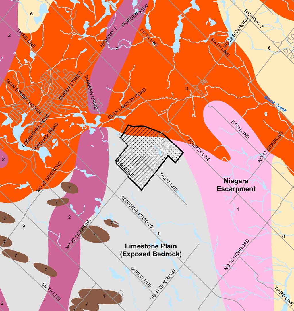

67
, MAP 2223, 2005.")

68 AD RO DE SI nd 22 Phase 1 (Extracted) 5t h LI N E RO AD Phase 2 (Extracted) 17 th SI DE Phase 3 (Active) SITE 4t h LI N E R EG IO N A L R O A D 25 MAP SOURCE: ONTARIO GEOLOGICAL SURVEY (OGS), MAP 2223, LEGEND QUATERNARY GEOLOGY 4th LINE RESIDENTIAL WATER SUPPLY INTERFERENCE COMPLAINTS THIRD-PARTY HYDROGEOLOGICAL ASSESSMENT AND RESOLUTION Acton Quarry, Town of Halton Hills DATE: MARCH 2009 SCALE: 1:50000 PROJECT: REF. NO.: F5-GE FIGURE Environmental Consulting Engineers 5
Hydrogeological Assessment for Part of Lots 2 and 3, Concession 5, Township of Thurlow, County of Hastings 1.0 INTRODUCTION. 1.
 February 10,2017 25506400 Ontario Ltd. Foxboro, ON Attention: Brad Newbatt Re: Hydrogeological Assessment for Part of Lots 2 and 3, Concession 5, Township of Thurlow, County of Hastings 1.0 INTRODUCTION
Connecticut's Aquifers
 Page 1 of 5 DEP Search: Connecticut's Aquifers The technical definition of the word "aquifer" is: any geologic formation capable of yielding significant quantities of water to wells. By that definition,
Buried-valley Aquifers: Delineation and Characterization from Reflection Seismic and Core Data at Caledon East, Ontario
 Buried-valley Aquifers: Delineation and Characterization from Reflection Seismic and Core Data at Caledon East, Ontario Russell, H.A.J. 1, S.E. Pullan 1, J.A. Hunter 1, D.R. Sharpe 1, and S. Holysh 2 1
patersongroup Mineral Aggregate Assessment 3119 Carp Road Ottawa, Ontario Prepared For Mr. Greg LeBlanc March 7, 2014 Report: PH2223-REP.
 Geotechnical Engineering Environmental Engineering group Hydrogeology Geological Engineering Archaeological Studies Materials Testing 3119 Carp Road Prepared For Mr. Greg LeBlanc March 7, 2014 Paterson
Groundwater Investigation SOUTHGATE GRAVEL PIT Part of Lot 15, Concession 15 (formerly Township of Proton), Township of Southgate.
, Township of Southgate.") Groundwater Investigation SOUTHGATE GRAVEL PIT Part of Lot 15, Concession 15 (formerly Township of Proton), Township of Southgate County of Grey October, 2014 Prepared for: Drysdale Aggregate Consulting
Groundwater Investigation SOUTHGATE GRAVEL PIT Part of Lot 15, Concession 15 (formerly Township of Proton), Township of Southgate County of Grey October, 2014 Prepared for: Drysdale Aggregate Consulting
The Niagara Escarpment extends from western New York, through the GTA all the way up to Manitoulin Island and into Michigan and Wisconsin.
 is southern Ontario s most prominent topographic feature, extending more than 500 kilometres from western New York, through Niagara Falls and the western part of the Greater Toronto Area (GTA), and north
TECHNICAL SUPPORT DOCUMENT # 1 COMPARATIVE EVALUATION OF ALTERNATIVE SITES APPENDIX TSD#1-H. Design & Operations Component
 TECHNICAL SUPPORT DOCUMENT # 1 COMPARATIVE EVALUATION OF ALTERNATIVE SITES APPENDIX TSD#1-H Design & Operations Component February 2013 February 2013 Design & Operations Component Appendix TSD#1-H COMPARATIVE
KANSAS GEOLOGICAL SURVEY Open File Report LAND SUBSIDENCE KIOWA COUNTY, KANSAS. May 2, 2007
 KANSAS GEOLOGICAL SURVEY Open File Report 2007-22 LAND SUBSIDENCE KIOWA COUNTY, KANSAS Prepared by Michael T. Dealy L.G., Manager, Wichita Operations SITE LOCATION The site was approximately four miles
THE MINISTRY OF ENERGY AND ENERGY INDUSTRIES MINERALS DIVISION MINE DESIGN TEMPLATE OPERATOR NAME: OPERATOR ADDRESS: PHONE NUMBER: FACSIMILE:
 THE MINISTRY OF ENERGY AND ENERGY INDUSTRIES MINERALS DIVISION MINE DESIGN TEMPLATE 1.0 GENERAL INFORMATION OPERATOR NAME: OPERATOR ADDRESS: PHONE NUMBER: FACSIMILE: NAME OF CONTACT: CELLULAR PHONE: EMAIL
,Baynes Lake. TO...?&.?...A 2...KO.?'!!&... Sr. *logical Engineer
 > i evernment OF BRITISH COLUMBIA a TO...?&.?...A 2....KO.?'!!&... Sr. *logical Engineer... Grou,,water. Section Hydrology Division Wat.er... In~.~s.tiga.ti.On.s..Branck.... 5 u BJECT...C;.roun.dw.ater...Snve
11/22/2010. Groundwater in Unconsolidated Deposits. Alluvial (fluvial) deposits. - consist of gravel, sand, silt and clay
 deposits. - consist of gravel, sand, silt and clay") Groundwater in Unconsolidated Deposits Alluvial (fluvial) deposits - consist of gravel, sand, silt and clay - laid down by physical processes in rivers and flood plains - major sources for water supplies
Groundwater in Unconsolidated Deposits Alluvial (fluvial) deposits - consist of gravel, sand, silt and clay - laid down by physical processes in rivers and flood plains - major sources for water supplies
Groundwater Hydrology
 EXERCISE 12 Groundwater Hydrology INTRODUCTION Groundwater is an important component of the hydrologic cycle. It feeds lakes, rivers, wetlands, and reservoirs; it supplies water for domestic, municipal,
Unit 3 Review - Surface Processes
 Unit 3 Review - Surface Processes 1. Why is the surface of Mercury covered with meteor impact craters, while Earth s surface has relatively few craters? A) Mercury is larger than Earth, so it gets hit
Geology and New England Landscapes
 Geology and New England Landscapes Jim Turenne, CPSS USDA-NRCS Warwick, RI. http://nesoil.com Why Geology? Provides the big picture of site conditions. Major part of soil formation (parent material and
Appendix I. Hydrogeology Report
 Appendix I Hydrogeology Report 101-17262-00 October 31, 13 Bruce Grundon GENIVAR Inc. 600 Cochrane Drive, Suite 500 Markham, ON L3R 5K3 Re: Dear Mr. Grundon: Please find attached a hydrogeological assessment
Geology and Soils. Technical Memorandum
 Geology and Soils Technical Memorandum TO: FDOT FROM: HDR, Inc. DATE: February 2013 PROJECT: St Johns River Crossing FPID No: 208225-3-21-01 Clay, Duval, and St. Johns Counties; Florida Geology and soils
NOA ASSESSMENT HARRIS QUARRY MENDOCINO COUNTY, CALIFORNIA TABLE OF CONTENTS
 NOA ASSESSMENT HARRIS QUARRY MENDOCINO COUNTY, CALIFORNIA TABLE OF CONTENTS Introduction... 1 Scope of Services... 1 Project Location and Description... 1 Geologic Setting... 1 Regional Geology... 1 Site
=%REPORT RECONNAISSANCE OF CHISHOLM LAKE PROSPECT. October 25, 1977
 =%REPORT ON FIELD RECONNAISSANCE OF CHISHOLM LAKE PROSPECT October 25, 1977 Bruce D. Vincent Imperial Oil Limited, Minerals - Coal, CALGARY, ALBERTA CHISHOLM LAKE PROSPECT Introduction The Chisholm Lake
GEOLOGY AND MINERAL RESOURCES OF INDIAN RESERVE 26
 ) 41HI3NW94I4 I R NO 26 1*A1 MANITOULIN ISLAND 010 -f?;. GEOLOGY AND MINERAL RESOURCES OF INDIAN RESERVE 26 September 16, 1975 D. G. Innes, Resident Geologist Sudbury District Ministry of Natural Resources
SECTION 4 TABLES. 1 Summary of Hydrogeologic Parameters for Various Stratigraphic Units FIGURES
 SECTION 4 4.0 OVERVIEW OF GEOLOGY AND HYDROGEOLOGY... 13 4.1 Comparison of East and West Sides of Study Area... 15 4.2 Bedrock Sequence... 17 4.3 Mancos Shale (Upper Cretaceous)... 18 4.4 Mesaverde Formation
Soils, Hydrogeology, and Aquifer Properties. Philip B. Bedient 2006 Rice University
 Soils, Hydrogeology, and Aquifer Properties Philip B. Bedient 2006 Rice University Charbeneau, 2000. Basin Hydrologic Cycle Global Water Supply Distribution 3% of earth s water is fresh - 97% oceans 1%
SL GEOLOGY AND MINING. Coal bearing strata in the project area are referable primarily to the Allegheny Group of
 SL-145-1 GEOLOGY AND MINING Coal bearing strata in the project area are referable primarily to the Allegheny Group of Pennsylvania age. These rocks occur as dissected remnants overlying the ridge-forming
GEOPHYSICAL IMAGING TO ENHANCE ANALYSIS, DESIGN AND DRILLING OF LARGE-SCALE GEOTHERMAL SYSTEMS. Abstract
 GEOPHYSICAL IMAGING TO ENHANCE ANALYSIS, DESIGN AND DRILLING OF LARGE-SCALE GEOTHERMAL SYSTEMS John A. Mundell, Mundell & Associates, Inc., Indianapolis, Indiana Gabriel Hebert, Mundell & Associates, Inc.,
MEMORANDUM. wa.tsr..-z.n~.e.s-t.i~at.i.o.ns... Branch... Mr. Webster contends that prior to excavation of the gravel
 TO... J. C. Foweraker 2... Head Gr o w a t er S e c t i on... Hyar....og~~~.~.~vis.ion... wa.tsr..-z.n~.e.s-t.i~at.i.o.ns... Branch... eernment OF BRITISH COLUMBIA MEMORANDUM II 0 PROM A. P. Kohut, Geological
Pratice Surface Processes Test
 1. The cross section below shows the movement of wind-driven sand particles that strike a partly exposed basalt cobble located at the surface of a windy desert. Which cross section best represents the
HYDROGEOLOGICAL PROPERTIES OF THE UG2 PYROXENITE AQUIFERS OF THE BUSHVELD COMPLEX
 R. Gebrekristos, P.Cheshire HYDROGEOLOGICAL PROPERTIES OF THE UG2 PYROXENITE AQUIFERS OF THE BUSHVELD COMPLEX R. Gebrekristos Digby Wells Environmental P. Cheshire Groundwater Monitoring Services Abstract
Wisconsin s Hydrogeology: an overview
 2012 Soil and Water Conservation Society Conference Stevens Point, WI Feb 9, 2012 Wisconsin s Hydrogeology: an overview Ken Bradbury Wisconsin Geological and Natural History Survey University of Wisconsin-Extension
1. The map below shows a meandering river. A A' is the location of a cross section. The arrows show the direction of the river flow.
 1. The map below shows a meandering river. A A' is the location of a cross section. The arrows show the direction of the river flow. Which cross section best represents the shape of the river bottom at
Delineation of Zones at Risk from Groundwater Inflows at an Underground Platinum Mine in South Africa
 Delineation of Zones at Risk from Groundwater Inflows at an Underground Platinum Mine in South Africa Mr Andreas Stoll andreas.stoll@erm.com Environmental Resources Management Swiss GmbH (ERM), Switzerland
How & Where does infiltration work? Summary of Geologic History Constraints/benefits for different geologic units
 June 26, 2007: Low Impact Development 1 Associated Earth Sciences, Inc. Associated Earth Sciences, Inc. Presented by: Matthew A. Miller, PE April 24, 2012 How & Where does infiltration work? Summary of
Hydrogeology of Karst NE Wisconsin. Dr. Maureen A. Muldoon UW-Oshkosh Geology Department
 Hydrogeology of Karst NE Wisconsin Dr. Maureen A. Muldoon UW-Oshkosh Geology Department WI Bedrock Outline Karst Landscapes Existing WQ Data Flow in Karst Aquifers Overview of Silurian Aquifer Water Level
Chapter 2. Regional Landscapes and the Hydrologic Cycle
 Chapter 2. Regional Landscapes and the Hydrologic Cycle W. Lee Daniels Department of Crop and Soil Environmental Sciences, Virginia Tech Table of Contents Introduction... 23 Soils and landscapes of the
KRIS wsbssm. IBHiiilll
 KRIS wsbssm IBHiiilll Digitized by the Internet Archive in 2012 with funding from University of Illinois Urbana-Champaign http://archive.org/details/engineeringaspec34ekbl STATE OF ILLINOIS HENRY HORNER,
the Quarrying Industry Dewatering and the Quarrying Industry the Quarrying Industry
 Dewatering and the Quarrying Industry Dewatering and Dewatering and the Quarrying Industry the Quarrying Industry Les Brown Eugene P. Daly John Kelly Objectives 1) To present a summary of water management
Proposed Cemetery Thornhill Road. Tier One Hydrogeological Risk Assessment. Peter Mitchell Associates
 Proposed Cemetery Thornhill Road Tier One Hydrogeological Risk Assessment Peter Mitchell Associates January 2015 Executive Summary This report uses a desk-based risk assessment technique published by the
Niagara Escarpment Baseflow Study
 Niagara Escarpment Baseflow Study Submitted to the Niagara Escarpment Commission Prepared by Allan Rodie Ryan Post Nottawasaga Valley Conservation Authority Utopia, Ontario January 27, 2009 1 Acknowledgements
Groundwater Resource Evaluation in Support of Dewatering a South Carolina Limestone Quarry
 Groundwater Resource Evaluation in Support of Dewatering a South Carolina Limestone Quarry Daniel T. Brantley 1, John M. Shafer 2, and Michael G. Waddell 3 AUTHORS: 1 Research Associate, Earth Sciences
Land subsidence due to groundwater withdrawal in Hanoi, Vietnam
 Land Subsidence (Proceedings of the Fifth International Symposium on Land Subsidence, The Hague, October 1995). 1AHS Publ. no. 234, 1995. 55 Land subsidence due to groundwater withdrawal in Hanoi, Vietnam
TAMPA BAY TRIBUTARIES BASIN. Hydrogeological Setting
 TAMPA BAY TRIBUTARIES BASIN Hydrogeological Setting Aquifers within the Tampa Bay Tributaries Basins ground water flow system include the Floridan aquifer system, the intermediate aquifer system, and the
HISTORY OF CONSTRUCTION FOR EXISTING CCR SURFACE IMPOUNDMENT PLANT GASTON ASH POND 40 CFR (c)(1)(i) (xii)
(1)(i) (xii)") HISTORY OF CONSTRUCTION FOR EXISTING CCR SURFACE IMPOUNDMENT PLANT GASTON ASH POND 40 CFR 257.73(c)(1)(i) (xii) (i) Site Name and Ownership Information: Site Name: E.C. Gaston Steam Plant Site Location:
HISTORY OF CONSTRUCTION FOR EXISTING CCR SURFACE IMPOUNDMENT PLANT GASTON ASH POND 40 CFR 257.73(c)(1)(i) (xii) (i) Site Name and Ownership Information: Site Name: E.C. Gaston Steam Plant Site Location:
Topic 6: Weathering, Erosion and Erosional-Deposition Systems (workbook p ) Workbook Chapter 4, 5 WEATHERING
 Workbook Chapter 4, 5 WEATHERING") Topic 6: Weathering, Erosion and Erosional-Deposition Systems (workbook p. 95-125) Workbook Chapter 4, 5 THE BIG PICTURE: Weathering, erosion and deposition are processes that cause changes to rock material
Topic 6: Weathering, Erosion and Erosional-Deposition Systems (workbook p. 95-125) Workbook Chapter 4, 5 THE BIG PICTURE: Weathering, erosion and deposition are processes that cause changes to rock material
July 16, 2004 JEGEL
 July 6, 004 GEOLOGICAL INVESTIGATION PROPOSED DOLOSTONE QUARRY PART OF LOT AND ALL OF LOTS AND 3, CONCESSION GEOGRAPHIC TOWNSHIP OF EAST FLAMBOROUGH CITY OF HAMILTON Prepared For LOWNDES HOLDINGS CORP.
Sediment and sedimentary rocks Sediment
 Sediment and sedimentary rocks Sediment From sediments to sedimentary rocks (transportation, deposition, preservation and lithification) Types of sedimentary rocks (clastic, chemical and organic) Sedimentary
REGIONAL GROUNDWATER MAPPING AN ASSESSMENT TOOL FOR INCORPORATING GROUNDWATER INTO THE PLANNING PROCESS
 REGIONAL GROUNDWATER MAPPING AN ASSESSMENT TOOL FOR INCORPORATING GROUNDWATER INTO THE PLANNING PROCESS Steve Holysh, Regional Municipality of Halton, Canada Jeff Pitcher, Grand River Conservation Authority,
Re: Steep Slope Assessment for 2465 Waverly Drive, Blind Bay, BC; Legal Address: Lot 39, Section 18, Township 22, Range 10, Plan 25579, W6M, KDYD.
 OEL File 1563-1 May 30, 2017 Doug Wall PO Box 774 Salmon Arm, BC V1E 4N7 Re: Steep Slope Assessment for 2465 Waverly Drive, Blind Bay, BC; Legal Address: Lot 39, Section 18, Township 22, Range 10, Plan
Our File: 92 F/1, 92 F/8. Numerous licenced springs occur north of the B.C. Hydro right-of-way on. Water Management Branch
 J.C. Foweraker, Head Groundwater Section Water Management Branch Date: May 23, 1986 Our File: 92 F/1, 92 F/8 Re: Groundwater - D.L. 117. Nanoose District As requested by Mr. B. Hollingshead, Regional Water
THE BEDROCK SURFACE AND FORMER DRAINAGE SYSTEMS OF MONTGOMERY COUNTY, OHIO 1
 THE BEDROCK SURFACE AND FORMER DRAINAGE SYSTEMS OF MONTGOMERY COUNTY, OHIO 1 STANLEY E. NORRIS, Geologist, U. S. Geological Survey, Columbus, Ohio INTRODUCTION The bedrock surface of Montgomery County,
Seismic Reflection Imaging across the Johnson Ranch, Valley County, Idaho
 Seismic Reflection Imaging across the Johnson Ranch, Valley County, Idaho Report Prepared for the Skyline Corporation Lee M. Liberty Center for Geophysical Investigation of the Shallow Subsurface (CGISS)
Environmental Assessment for a New Landfill Footprint at the West Carleton Environmental Centre
 Waste Management of Canada Corporation Environmental Assessment for a New Landfill Footprint at the West Carleton Environmental Centre GEOLOGY AND HYDROGEOLOGY EXISTING CONDITIONS REPORT Prepared by: WESA
Name: Which rock layers appear to be most resistant to weathering? A) A, C, and E B) B and D
 A, C, and E B) B and D") Name: 1) The formation of soil is primarily the result of A) stream deposition and runoff B) precipitation and wind erosion C) stream erosion and mass movement D) weathering and biological activity 2)
Name: 1) The formation of soil is primarily the result of A) stream deposition and runoff B) precipitation and wind erosion C) stream erosion and mass movement D) weathering and biological activity 2)
MAPPING BEDROCK: Verifying Depth to Bedrock in Calumet County using Seismic Refraction
 MAPPING BEDROCK: Verifying Depth to Bedrock in Calumet County using Seismic Refraction Revised December 13, 2011 Dave Hart Wisconsin Geological and Natural History Survey INTRODUCTION Seismic refraction
Impact of the Danube River on the groundwater dynamics in the Kozloduy Lowland
 GEOLOGICA BALCANICA, 46 (2), Sofia, Nov. 2017, pp. 33 39. Impact of the Danube River on the groundwater dynamics in the Kozloduy Lowland Peter Gerginov Geological Institute, Bulgarian Academy of Sciences,
Name. 4. The diagram below shows a soil profile formed in an area of granite bedrock. Four different soil horizons, A, B, C, and D, are shown.
 Name 1. In the cross section of the hill shown below, which rock units are probably most resistant to weathering? 4. The diagram below shows a soil profile formed in an area of granite bedrock. Four different
Devil s Punchbowl -Virtual Field Trip-
 Devil s Punchbowl -Virtual Field Trip- School of GEOGRAPHY & GEOLOGY Carolyn Eyles & Susan Vajoczki Prepared by Zachary Windus and Liz Kenny From McMaster University take Main Street West towards Ancaster.
Prof. Stephen A. Nelson EENS 111. Groundwater
 Page 1 of 8 Prof. Stephen A. Nelson EENS 111 Tulane University Physical Geology This page last updated on 20-Oct-2003 is water that exists in the pore spaces and fractures in rock and sediment beneath
mountain rivers fixed channel boundaries (bedrock banks and bed) high transport capacity low storage input output
 high transport capacity low storage input output") mountain rivers fixed channel boundaries (bedrock banks and bed) high transport capacity low storage input output strong interaction between streams & hillslopes Sediment Budgets for Mountain Rivers Little
mountain rivers fixed channel boundaries (bedrock banks and bed) high transport capacity low storage input output strong interaction between streams & hillslopes Sediment Budgets for Mountain Rivers Little
ENGINEER S CERTIFICATION OF FAULT AREA DEMONSTRATION (40 CFR )
") PLATTE RIVER POWER AUTHORITY RAWHIDE ENERGY STATION BOTTOM ASH TRANSFER (BAT) IMPOUNDMENTS LARIMER COUNTY, CO ENGINEER S CERTIFICATION OF FAULT AREA DEMONSTRATION (40 CFR 257.62) FOR COAL COMBUSTION RESIDUALS
PLATTE RIVER POWER AUTHORITY RAWHIDE ENERGY STATION BOTTOM ASH TRANSFER (BAT) IMPOUNDMENTS LARIMER COUNTY, CO ENGINEER S CERTIFICATION OF FAULT AREA DEMONSTRATION (40 CFR 257.62) FOR COAL COMBUSTION RESIDUALS
Karst Investigation of the Duntroon Quarry Expansion Lands
 Karst Investigation of the Duntroon Quarry Expansion Lands October 3, 2007 Prepared for: Jagger Hims Limited Prepared by: Marcus J. Buck, Marcus J. Buck Karst Solutions Dr. Stephen R.H. Worthington, Executive
THE STRUCTURE AND THICKNESS OF THE CLINTON AND BEREA FORMATIONS IN THE VICINITY OF WOOSTER, OHIO
 THE STRUCTURE AND THICKNESS OF THE CLINTON AND BEREA FORMATIONS IN THE VICINITY OF WOOSTER, OHIO KARL VER STEEG College of Wooster INTRODUCTION AND ACKNOWLEDGMENTS The data used in the construction of
Ground-Water Exploration in the Worthington Area of Nobles County: Summary of Seismic Data and Recent Test Drilling Results
 Ground-Water Exploration in the Worthington Area of Nobles County: Summary of Seismic Data and Recent Test Drilling Results Jim Berg and Todd Petersen Geophysicists, DNR Waters January 2000 Table of Contents
Which landscape best represents the shape of the valleys occupied by glaciers? A) B) C) D)
 B) C) D)") 1. Glaciers often form parallel scratches and grooves in bedrock because glaciers A) deposit sediment in unsorted piles B) deposit rounded sand in V-shaped valleys C) continually melt and refreeze D) drag
1. Glaciers often form parallel scratches and grooves in bedrock because glaciers A) deposit sediment in unsorted piles B) deposit rounded sand in V-shaped valleys C) continually melt and refreeze D) drag
The Welsh Borderland. Geologically recent surface deposits. The Welsh Borderland
 The Welsh Borderland This account provides a broad perspective of the geology of the Welsh Borderland region which comprises the southeast of Powys, southern Shropshire, northern Gwent, the western half
Betsy Stevenson and Allison Mohrs (Skagit County Planning and Development Services) Jenny Baker, The Nature Conservancy
 Jenny Baker, The Nature Conservancy") TC Fisher Slough Final Design and Permitting Subject: Well Review Memorandum To: From: Betsy Stevenson and Allison Mohrs (Skagit County Planning and Development Services) Jenny Baker, The ature Conservancy
TC Fisher Slough Final Design and Permitting Subject: Well Review Memorandum To: From: Betsy Stevenson and Allison Mohrs (Skagit County Planning and Development Services) Jenny Baker, The ature Conservancy
The Geology of Sebago Lake State Park
 Maine Geologic Facts and Localities September, 2002 43 55 17.46 N, 70 34 13.07 W Text by Robert Johnston, Department of Agriculture, Conservation & Forestry 1 Map by Robert Johnston Introduction Sebago
THE OHIO JOURNAL OF SCIENCE
 THE OHIO JOURNAL OF SCIENCE VOL. LI JANUARY 1951 No. 1 SHORE EROSION ON SANDUSKY BAY PAUL R. SHAFFER Department of Geology, University of Illinois, Urbana, 111. The south shore of San dusky Bay is undergoing
2 Aggregates in Indiana
 2 Aggregates in Indiana Origin of Aggregates Gravel and Natural Sands Crushed Stone Slag Distribution of Aggregates Glacial Deposits Bedrock Deposits Aggregate Types Natural Aggregates Artificial Aggregates
Ontario Ministry of Northern Development and Mines Submission to the Joint Review Panel Public Hearing Proposed Bruce Deep Geological Repository
 Ontario Ministry of Northern Development and Mines Submission to the Joint Review Panel Public Hearing Proposed Bruce Deep Geological Repository August 27, 2013 Background and Scope June 18, 2013, the
Evaluation of Subsurface Formation of Pabna District, Bangladesh
 IOSR Journal of Applied Geology and Geophysics (IOSR-JAGG) e-issn: 2321 0990, p-issn: 2321 0982.Volume 1, Issue 4 (Sep. Oct. 2013), PP 30-36 Evaluation of Subsurface Formation of Pabna District, Bangladesh
Page 1. Name:
 Name: 1) Which property would best distinguish sediment deposited by a river from sediment deposited by a glacier? thickness of sediment layers age of fossils found in the sediment mineral composition
For Sale - 56 Acre Sandstone Quarry State Route 511, Oberlin/Kipton, OH 44075
 14647 State Route 511, Oberlin/Kipton, OH 44075 56 ACRES Vermilion Rd Gifford Rd Haigh Rd 44 Summary The Kipton sandstone quarry is included in 56 acre tract owned by Terry A. Johnson, of Huron, Ohio.
Geotechnical Report McCormick Pit
 Geotechnical Report McCormick Pit Part of Lot 12, Concession 2 EHS Town of Caledon, Region of Peel For Blueland Farms Limited February 2013 Prepared by Harrington McAvan Ltd 6882 14 th Avenue, Markham,
GPR AS A COST EFFECTIVE BEDROCK MAPPING TOOL FOR LARGE AREAS. Abstract
 GPR AS A COST EFFECTIVE BEDROCK MAPPING TOOL FOR LARGE AREAS Dr. Jutta L. Hager, Hager GeoScience, Inc., Waltham, MA Mario Carnevale, Hager GeoScience, Inc., Waltham, MA Abstract Hager GeoScience, Inc.
RIVERS, GROUNDWATER, AND GLACIERS
 RIVERS, GROUNDWATER, AND GLACIERS Delta A fan-shaped deposit that forms when a river flows into a quiet or large body of water, such as a lake, an ocean, or an inland sea. Alluvial Fan A sloping triangle
Basin Analysis Applied to Modelling Buried Valleys in the Great Lakes Basin
 EARTH SCIENCES SECTOR GENERAL INFORMATION PRODUCT 35 Basin Analysis Applied to Modelling Buried Valleys in the Great Lakes Basin Sharpe, D R; Russell, H A J 2004 Originally released as: Basin Analysis
Groundwater Modeling for Flow Systems with Complex Geological and Hydrogeological Conditions
 Available online at www.sciencedirect.com Procedia Earth and Planetary Science 3 ( 2011 ) 23 28 2011 Xi an International Conference on Fine Geological Exploration and Groundwater & Gas Hazards Control
Lab 7: Sedimentary Structures
 Name: Lab 7: Sedimentary Structures Sedimentary rocks account for a negligibly small fraction of Earth s mass, yet they are commonly encountered because the processes that form them are ubiquitous in the
Cattaraugus Creek: A Story of Flowing Water and the Geology of the Channel It Flows Through Presentation to West Valley Citizen Task Force 4/27/16
 Cattaraugus Creek: A Story of Flowing Water and the Geology of the Channel It Flows Through Presentation to West Valley Citizen Task Force 4/27/16 Raymond C. Vaughan, Ph.D. What happens if you drop a
HW #2 Landscape Travel from A to B 12,
 HW #2 Landscape 2016 Section: Name: ate: 1. ase your answer(s) to the following question(s) on the map below, which represents two bridges that cross the Green River. Letters,, and represent locations
L.O: SLOWING STREAMS DEPOSIT (SORT) SEDIMENT HORIZONTALLY BY SIZE.
 SEDIMENT HORIZONTALLY BY SIZE.") L.O: SLOWING STREAMS DEPOSIT (SORT) SEDIMENT HORIZONTALLY BY SIZE. 1. Base your answer to the following question on the profile shown below, which shows the pattern of horizontal sorting produced at a
L.O: SLOWING STREAMS DEPOSIT (SORT) SEDIMENT HORIZONTALLY BY SIZE. 1. Base your answer to the following question on the profile shown below, which shows the pattern of horizontal sorting produced at a
' International Institute for Land Reclamation and Improvement. 2 Groundwater Investigations. N.A. de Ridder'? 2.1 Introduction. 2.
 2 Groundwater Investigations N.A. de Ridder'? 2.1 Introduction Successful drainage depends largely on a proper diagnosis of the causes of the excess water. For this diagnosis, one must consider: climate,
THE QUATERNARY GEOLOGY OF NEWARK BAY AND KILL VAN KULL CHANNEL, NEW YORK AND NEW JERSEY. and
 THE QUATERNARY GEOLOGY OF NEWARK BAY AND KILL VAN KULL CHANNEL, NEW YORK AND NEW JERSEY Stephanie Beda, W. Bruce Ward, William Murphy, Robert Fleming, Gary Fleming, Beckett Boyd Earthworks LLC 27 Glen
Vulnerability Analysis for the Milton and Campbellville Wellfields, Regional Municipality of Halton, Ontario
 Final Report Vulnerability Analysis for the Milton and Campbellville Wellfields, Regional Municipality of Halton, Ontario Prepared For: The Regional Municipality of Halton Planning and Public Works 1151
Hydraulic Impacts of Limestone Quarries and Gravel Pits. Jeff Green Minnesota DNR-Division of Ecological & Water Resources
 Hydraulic Impacts of Limestone Quarries and Gravel Pits Jeff Green Minnesota DNR-Division of Ecological & Water Resources The Hydraulic Impacts of Limestone Quarries and Gravel Pits Study was funded by
Page 1. Name:
 Name: 1) Which event is the best example of erosion? dissolving of rock particles on a limestone gravestone by acid rain breaking apart of shale as a result of water freezing in a crack rolling of a pebble
Maggie Payne Jim Turenne
 Maggie Payne Jim Turenne USDA-NRCS 60 Quaker Lane, Suite 46 Warwick, RI. 02886 401-822-8832 maggie.payne@ri.usda.gov U.S. Department of Agriculture 1935: Soil Conservation Service (SCS) Natural Resources
Report on Exploratory Drilling. Prospecting Claim Nos and
 Report on Exploratory Drilling Prospecting Claim Nos. 4212342 and 4212343 Glamorgan Township, Lot 34, Concession IV: Southern Ontario Mining Division Exploratory Drilling Program Site Work: November 11-17,2008
I DES TERRAINS DIVISION. D. F. VanDine TERRAIN SCIENCES RESOURCE INVENTORY - MACKFWIE. Scale 1 : 250,000. D. E. Lawrence LA DIV'3'QN DE LA SCIENCE
 GRAN- RESOURCE INVENTORY - MACKFWIE LAC BELOT NTS 96 L SW4 Scale 1 : 250,000 D. E. Lawrence D. F. VanDine For: Department of Indian and Northern Affairs TERRAIN SCIENCES DIVISION LA DIV'3'QN DE LA SCIENCE
Regional groundwater mapping and model
 Regional groundwater mapping and model Boyd, Dwight 1, Steve Holysh 2, and Jeff Pitcher 1 1 Grand River Conservation Authority, Canada; 2 Regional Municipality of Halton, Canada The Grand River forms one
THE OHIO JOURNAL OF SCIENCE
 THE OHIO JOURNAL OF SCIENCE VOL. LIII MARCH, 1953 No. 2 SUBSURFACE STUDY OF GLACIAL DEPOSITS AT CLEVELAND, OHIO C. T. BAGLEY Sverdrup & Parcel, Inc., Consulting Engineers, St. Lotus, Mo. The soil 1 strata
The boulder was most likely moved to this location by A) glacial ice B) prevailing wind C) streamfiow D) volcanic action
 glacial ice B) prevailing wind C) streamfiow D) volcanic action") 1. Which rock material was most likely transported to its present location by a glacier? A) rounded sand grains found in a river delta B) rounded grains found in a sand dune C) residual soil found on a
1. Which rock material was most likely transported to its present location by a glacier? A) rounded sand grains found in a river delta B) rounded grains found in a sand dune C) residual soil found on a
patersongroup Consulting Engineers April 20, 2010 File: PG1887-LET.01R Novatech Engineering Consultants Suite 200, 240 Michael Cowpland Drive
 patersongroup April 20, 2010 File: PG1887-LET.01R Novatech Engineering Consultants Suite 200, 240 Michael Cowpland Drive Ottawa, Ontario K2M 1P6 Attention: Mr. Adam Thompson Consulting Engineers 28 Concourse
An Evaluation of Pavement Drainage Interstate 64, Rowan-Carter Counties
 Transportation Kentucky Transportation Center Research Report University of Kentucky Year 1984 An Evaluation of Pavement Drainage Interstate 64, Rowan-Carter Counties David L. Allen Herbert F. Southgate
Lecture Outline Wednesday - Friday February 14-16, 2018
 Lecture Outline Wednesday - Friday February 14-16, 2018 Quiz 2 scheduled for Friday Feb 23 (Interlude B, Chapters 6,7) Questions? Chapter 6 Pages of the Past: Sedimentary Rocks Key Points for today Be
HYBRID DETERMINISTIC AND STOCHASTIC HYDROSTRATIGRAPHIC MODELING OF A COMPLEX GLACIAL AQUIFER SYSTEM
 HYBRID DETERMINISTIC AND STOCHASTIC HYDROSTRATIGRAPHIC MODELING OF A COMPLEX GLACIAL AQUIFER SYSTEM Lawrence D. Lemke, Andrew L. Frahm, Lena K. Pappas Department of Geology, Wayne State University, Detroit,
4.3. Geomorphologic route along the Urasalakh River
 The Expedition Lena-Anabar 2003 4 Periglacial studies around Cape Mamontov Klyk 4.3. Geomorphologic route along the Urasalakh River Dimitri Bolshiyanov and Alexander Makarov 4.3.1 Structure of Quaternary
Evolution of the conceptual hydrogeologic and ground-water flow model for Las Vegas Valley, Clark County, Nevada
 Evolution of the conceptual hydrogeologic and ground-water flow model for Las Vegas Valley, Clark County, Nevada Geological Society of America Annual Meeting November 14, 2 David J. Donovan Southern Nevada
June 9, R. D. Cook, P.Eng. Soils Engineer Special Services Western Region PUBLIC WORKS CANADA WESTERN REGION REPORT ON
 PUBLIC WORKS CANADA WESTERN REGION REPORT ON GEOTECHNICAL INVESTIGATION PROPOSED MARTIN RIVER BRIDGE MILE 306.7 MACKENZIE HIGHWAY Submitted by : R. D. Cook, P.Eng. Soils Engineer Special Services Western
GEOL.3250 Geology for Engineers Glacial Geology
 GEOL.3250 Geology for Engineers Glacial Geology NAME Part I: Continental Glaciation Continental glaciers are large ice sheets that cover substantial portions of the land area. In the region of accumulation
CJ AREA MAPPED IN 1978 FOR QUATERNARY GEOLOGY ~ AREA MAPPED IN FOR QUATERNARY GEOLOGY. I I I j I I I -44-
 -44- ~. ~/
SUPPLEMENTAL MATERIAL
 SUPPLEMENTAL MATERIAL DESCRIPTIONS OF OTHER STRATIGRAPHIC SECTIONS Cherry Creek In its middle reaches, Cherry Creek meanders between three paired terraces within a narrow bedrock valley. The highest is