ENGINEERING MECHANICS BAA1113. Chapter 4: Force System Resultants (Static)
|
|
|
- Juniper Wiggins
- 5 years ago
- Views:
Transcription
 by Pn")

1 ENGINEERING MECHANICS BAA1113 Chapter 4: Force System Resultants (Static) by Pn Rokiah Bt Othman Faculty of Civil Engineering & Earth Resources
2 Chapter Description Aims To explain the Moment of Force (2D-scalar formulation & 3D-Vector formulation) To explain the Principle Moment To explain the Moment of a Couple To explain the Simplification of a Force and Couple System To explain the Reduction of Simple Distributed Loading Expected Outcomes Able to solve the problems of MOF and COM in the mechanics applications by using principle of moments References Russel C. Hibbeler. Engineering Mechanics: Statics & Dynamics, 14 th Edition
3 Chapter Outline 4.1 Moment of Force (MOF) Part I 4.2 Principle of Moment Part II 4.3 Moment of Couple (MOC) Part III 4.4 Simplification of a Force and Couple System 4.5 Reduction of Simple Distributed Loading- part IV


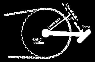
4 4.1 Moment of a Force Moment can be defined as turning force The tendency of a force to rotate a rigid body about any defined axis is called the moment of the force about the axis It is also called a torque or twist moment that tendency of a force to rotate a body about the axis It is a vector, so its has both magnitude and direction (right handrule) +ve CCW & -ve CW Unit used is N.m In a 2-D case, the magnitude of the moment What is Moment? M o = F d Perpendicular distance between the point about which the moment is required and the line of action of force Force acting on the body

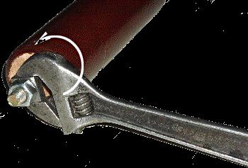


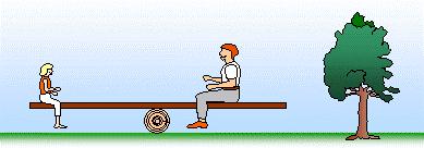

5 Application of Moment (turning effect) Causes of motion Day life activitymoment arm How does wheel size affect performance? Seesaw-how to balance?

")

")


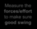
6 Application of Moment (turning effect) Measure the forces (weight transfer) and moment arm Measure the moment arm(length) to produce rotary power Measure the forces/effort to make sure good swing Measure the forces/effort to make sure good swing
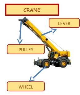

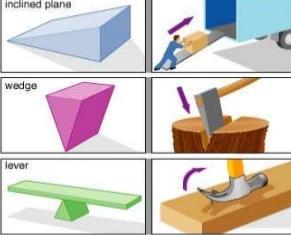
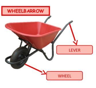


7 Application of Moment (turning effect) Measure the input forces and level to make sure output force Measure the effort/ load to make easy work


8 Moment factor MOF is bigger if the force is bigger MOF is bigger if acts further from the pivot MOF is bigger if it acts at 90 to the body it acts on


9 Moment of a force in 2-D (scalar formulation) Magnitude M O = Fd d is the perpendicular distance from point O to the line of action of the force b O d M O = F d a F direction is counter-clockwise. Direction Direction of M O is specified by using right hand rule direction of M O is either clockwise (CW) or counterclockwise (CCW), depending on the tendency for rotation M Ro = Fd


10 Moment of a force in 2-D (scalar formulation) Moment of a force does not always cause rotation Force F tends to rotate the beam clockwise about A with moment M A = F d A Force F tends to rotate the beam clockwise about B with moment M B = F d B Hence support at A prevents the rotation

 Step 4: use formula M O = Fd = (100")
11 Example 4.1 This is an example of a 2-D or coplanar force system. Determine the MOF about point O Step 3: assume tendency to rotate/ moment Step 1: FBD (Sketch outline shape) Step 2: det. The line of action/ moment arm (d) Step 4: use formula M O = Fd = (100 N) (2 m) = 200 Nm (CW)
 (0.75 m) = 37.5 Nm (CW) Step 2: det.")
12 Solution Example 4.1 This is an example of a 2-D or coplanar force system. Determine the MOF about point O M O = Fd = (50 N) (0.75 m) = 37.5 Nm (CW) Step 2: det. The line of action/ moment arm (d) M O = Fd = (40 N) (4 m + 2 cos 30 m) = 229 Nm (CW)
 M O = Fd = (60 N) (1 sin 45 m) = 42.4 Nm (CCW) Step 2: det.")
13 Solution Example 4.1 This is an example of a 2-D or coplanar force system. Determine the MOF about point O Step 3: assume tendency to rotate/ moment Step 2: det. The line of action/ moment arm (d) M O = Fd = (60 N) (1 sin 45 m) = 42.4 Nm (CCW) Step 2: det. The line of action/ moment arm (d) M O = Fd = (7 kn) (4 m -1 m) = 21 knm (CW)
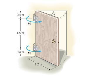
14 Example 4.2 This is an example of a 2-D or coplanar force system. Determine the moments of the 800 N force acting on the frame about points A,B,C and D Step 1: FBD (Sketch outline shape) Step 2: det. The line of action/ moment arm (d) Step 3: assume tendency to rotate/ moment Step 4: use formula M A = Fd = (800 N) ( m) = 2000 Nm (CW)
15 Solution Example 4.2 This is an example of a 2-D or coplanar force system. Determine the moments of the 800 N force acting on the frame about points A,B,C and D Step 1: FBD (Sketch outline shape) Step 2: det. The line of action/ moment arm (d) Step 3: assume tendency to rotate/ moment Step 4: use formula M B = Fd = (800 N) (1.5 m) = 1200 Nm (CW)
16 Example 4.2 This is an example of a 2-D or coplanar force system. Determine the moments of the 800 N force acting on the frame about points A,B,C and D Moment is zero Step 2: line of action F passes through C Step 4: use formula M C = Fd = (800 N) ( 0 m) = 0 Nm
17 Solution Example 4.2 This is an example of a 2-D or coplanar force system. Determine the moments of the 800 N force acting on the frame about points A,B,C and D Step 3: assume tendency to rotate/ moment Step 2: det. The line of action/ moment arm (d) Step 4: use formula M D = Fd = (800 N) (0.5 m) = 400 Nm (CCW)


(3sin 30 (40N)(4m 3cos30 334N. m 334N.")
18 Solution Example 4.3 This is an example of a 2-D or coplanar force system. Determine the moments of the four force acting on the rod about point O Step 4: use formula Step 3: assume moment acts in + y direction M M Ro Ro Fd ( 50N)(2m) (60N)(0m) (20N)(3sin 30 (40N)(4m 3cos30 334N. m 334N. m( CW ) m) m) Step 2: det. The line of action/ moment arm (d) for each forces
19 Example 4.4 Determine the moments of the 100 N force acting on the frame about point O assume moment acts in + y direction Resolve forces into x & y

20 Solution Example 4.4 Determine the moments of the 100 N force acting on the frame about point O assume moment acts in + y direction Resolve forces into x & y + F y = 100 (3/5) N + F x = 100 (4/5) N + M O = { 100 (3/5)N (5 m) (100)(4/5)N (2 m)} N m = 460 N m or 460 N m CW
 and time consuming It it easier to use vector cross product M O = r F r is the position vector from point O to any point on the line of action of")
21 Moment of a force in 3-D (Vector formulation) Moments in 3-D can be calculated using scalar (2-D) approach, but it can be difficult (finding d when forces in 3-D) and time consuming It it easier to use vector cross product M O = r F r is the position vector from point O to any point on the line of action of F
 i (r x F z - r z F x ) j + (r x F y - r y")
22 Moment of a force in 3-D (Vector formulation) Moment can be expressed as By expanding the above equation using 2 2 determinants M O = (r y F z - r z F y ) i (r x F z - r z F x ) j + (r x F y - r y F x ) k


23 Cross Product What is vector cross product? It is a vector operation 0 θ 180 The cross product of two vectors A and B results in vector C C = A B The magnitude and direction of the resulting vector can be written as C = A B = A B sin u C Scalar A B sin defines the magnitude of vector C Unit vector u C defines the direction of vector C

24 Cross Product Laws of Operations 1. Commutative law is not valid A X B B X A Rather, A X B = - B X A Shown by the right hand rule Cross product A X B yields a vector opposite in direction to C B X A = -C
25 Cross Product Laws of Operations 2. Multiplication by a Scalar a( A X B ) = (aa) X B = A X (ab) = ( A X B )a 3. Distributive Law A X ( B + D ) = ( A X B ) + ( A X D ) Proper order of the cross product must be maintained since they are not commutative

(j)(sin90 ) =")


26 Cross Product Direction is determine using right hand rule Cartesian Vector Formulation Use C = AB sinθ on pair of Cartesian unit vectors i j = k For i X j, (i)(j)(sin90 ) = (1)(1)(1) = 1 Use the circle for the results Crossing CCW yield positive CW yields negative results i j = k j k = i k i = j i k = -j k j = -i j i = -k vector crossed into itself is zero i i = 0 j j = 0 k k = 0


27 Cross Product Rules Cross product can be written as a determinant Each component can be determine using 2X2 determinants
28 Example 4.5 Determine the resultant moment by forces about point O Given: F 1 ={100 i j + 75 k}lb F 2 ={-200 i +250 j k}lb Step 4: use formula F = F 1 + F 2 M O = r OA F r OA?
 i + (-120 + 250) j + (75 + 100) k} lb = {-100 i +130 j + 175 k} lb r OA r OA = {4 i + 5 j + 3 k} ft")
29 Solution Example 4.5 Determine the resultant moment by forces about point O F = F 1 + F 2 = { ( ) i + ( ) j + ( ) k} lb = {-100 i +130 j k} lb r OA r OA = {4 i + 5 j + 3 k} ft Use vector cross product M O = r OA F i j k M O = = [{5(175) 3(130)} i {4(175) 3(-100)} j + {4(130) 5(-100)} k] ft lb = {485 i 1000 j k} ft lb
30 Example 4.6 Determine the moment of F about point A Step 4: use formula M O = r AC F F? r AC?
 sin 40 i + (80")

31 Solution Example 4.6 Determine the moment of F about point A F ={ (80 cos30) sin 40 i + (80 cos30) cos 40 j 80 sin30 k} N ={44.53 i j 40 k } N r AC ={0.55 i j 0.2 k } m Det. moment by using cross product M O M A = = r AC F i j k = { i j k } N m
32 Example 4.7 The pole is subjected to a 60N force that is directed from C to B. Determine the magnitude of the moment created by this force about the support at A
33 Solution example 4.7 Either one of the two position vectors can be used for the solution, since M A = r B x F or M A = r C x F Position vectors are represented as r B = {1i + 3j + 2k} m and r C = {3i + 4j} m Force F has magnitude 60N and is directed from C to B
34 k j i k j i XF r M N k j i k j i N u N F B A F 3(40)] 20) [1( 40)] 2( [1(40) 20)] 2( [3(40) (2) 1) ( 2) ( 0) 92 4) 93 3) (1 ) (60 ) ( Solution example 4.7
35 N m M N m k j i M k j i k j i XF r M A A C A. 224 (100) (120) (160) (40)] 20) [3( 40)] 0( [3(40) 20)] 0( [4(40) Solution example 4.7
36 Example 4.8 Three forces act on the rod. Determine the resultant moment they create about the flange at O and determine the coordinate direction angles of the moment axis
37 Solution example 4.8 Position vectors are directed from point O to each force r A = {5j} m and r B = {4i + 5j - 2k} m For resultant moment about O, M Ro i rxf) j k ra XF1 i j rb XF k r i XF j ( 2 C k 30i 40 j 60kN. m
38 For magnitude M Solution example 4.8 Ro (30) 2 ( 40) (60) 78.10N. m For unit vector defining the direction of moment axis, 2 2 u M Ro 30i 40 j 60k M Ro i j k
39 Solution example 4.8 For the coordinate angles of the moment axis, cos cos ; 121 cos ; ;
40 Conclusion of The Chapter 4 Conclusions - The Moment of a Force been identified - The Vector cross product have been implemented to solve Moment problems in Coplanar Forces Systems
41 Credits to: Dr Nurul Nadhrah Bt Tukimat En Khalimi Johan bin Abd Hamid Roslina binti Omar
ENGINEERING MECHANICS BAA1113
 ENGINEERING MECHANICS BAA1113 Chapter 3: Equilibrium of a Particle (Static) by Pn Rokiah Bt Othman Faculty of Civil Engineering & Earth Resources rokiah@ump.edu.my Chapter Description Aims To explain the
Chapter -4- Force System Resultant
 Ishik University / Sulaimani Civil Engineering Department Chapter -4- Force System Resultant 1 2 1 CHAPTER OBJECTIVES To discuss the concept of the moment of a force and show how to calculate it in two
ENGR-1100 Introduction to Engineering Analysis. Lecture 9
 ENGR-1100 Introduction to Engineering Analysis Lecture 9 MOMENT OF A FORCE (SCALAR FORMULATION), CROSS PRODUCT, MOMENT OF A FORCE (VECTOR FORMULATION), & PRINCIPLE OF MOMENTS Today s Objectives : Students
Chapter 4 Force System Resultant Moment of a Force
 Chapter 4 Force System Resultant Moment of a Force MOMENT OF A FORCE SCALAR FORMULATION, CROSS PRODUCT, MOMENT OF A FORCE VECTOR FORMULATION, & PRINCIPLE OF MOMENTS Today s Objectives : Students will be
Ishik University / Sulaimani Architecture Department Structure ARCH 214 Chapter -4- Force System Resultant
 Ishik University / Sulaimani Architecture Department 1 Structure ARCH 214 Chapter -4- Force System Resultant 2 1 CHAPTER OBJECTIVES To discuss the concept of the moment of a force and show how to calculate
Force System Resultants. Engineering Mechanics: Statics
 Force System Resultants Engineering Mechanics: Statics Chapter Objectives To discuss the concept of the moment of a force and show how to calculate it in 2-D and 3-D systems. Definition of the moment of
five moments ELEMENTS OF ARCHITECTURAL STRUCTURES: FORM, BEHAVIOR, AND DESIGN DR. ANNE NICHOLS SPRING 2014 lecture ARCH 614
 ELEMENTS OF ARCHITECTURAL STRUCTURES: FORM, BEHAVIOR, AND DESIGN DR. ANNE NICHOLS SPRING 2014 lecture five moments Moments 1 Moments forces have the tendency to make a body rotate about an axis http://www.physics.umd.edu
MOMENT OF A FORCE ABOUT A POINT
 MOMENT OF A FORCE ABOUT A POINT The tendency of a body to rotate about an axis passing through a specific point O when acted upon by a force (sometimes called a torque). 1 APPLICATIONS A torque or moment
Moment of a force (scalar, vector ) Cross product Principle of Moments Couples Force and Couple Systems Simple Distributed Loading
 Cross product Principle of Moments Couples Force and Couple Systems Simple Distributed Loading") Chapter 4 Moment of a force (scalar, vector ) Cross product Principle of Moments Couples Force and Couple Systems Simple Distributed Loading The moment of a force about a point provides a measure of the
Chapter 4 Moment of a force (scalar, vector ) Cross product Principle of Moments Couples Force and Couple Systems Simple Distributed Loading The moment of a force about a point provides a measure of the
Engineering Mechanics Statics
 Mechanical Systems Engineering_2016 Engineering Mechanics Statics 6. Moment of a Couple Dr. Rami Zakaria Moment of a Couple We need a moment (or torque) of (12 N m) to rotate the wheel. Notice that one
MOMENT OF A FORCE SCALAR FORMULATION, CROSS PRODUCT, MOMENT OF A FORCE VECTOR FORMULATION, & PRINCIPLE OF MOMENTS
 MOMENT OF A FORCE SCALAR FORMULATION, CROSS PRODUCT, MOMENT OF A FORCE VECTOR FORMULATION, & PRINCIPLE OF MOMENTS Today s Objectives : Students will be able to: a) understand and define moment, and, b)
SIMPLIFICATION OF FORCE AND COUPLE SYSTEMS & THEIR FURTHER SIMPLIFICATION
 SIMPLIFICATION OF FORCE AND COUPLE SYSTEMS & THEIR FURTHER SIMPLIFICATION Today s Objectives: Students will be able to: a) Determine the effect of moving a force. b) Find an equivalent force-couple system
MOMENT OF A COUPLE. Today s Objectives: Students will be able to. a) define a couple, and, b) determine the moment of a couple.
 define a couple, and, b) determine the moment of a couple.") Today s Objectives: Students will be able to MOMENT OF A COUPLE a) define a couple, and, b) determine the moment of a couple. In-Class activities: Check Homework Reading Quiz Applications Moment of a Couple
Today s Objectives: Students will be able to MOMENT OF A COUPLE a) define a couple, and, b) determine the moment of a couple. In-Class activities: Check Homework Reading Quiz Applications Moment of a Couple
Moments and Torques. M = F d
 Moments and Torques When a force is applied to an object, the object reacts in six possible ways. It can elongate, compress, translate (moves left, right, up, down, etc.), bend, twist or rotate. The study
Course Overview. Statics (Freshman Fall) Dynamics: x(t)= f(f(t)) displacement as a function of time and applied force
 Dynamics: x(t)= f(f(t)) displacement as a function of time and applied force") Course Overview Statics (Freshman Fall) Engineering Mechanics Dynamics (Freshman Spring) Strength of Materials (Sophomore Fall) Mechanism Kinematics and Dynamics (Sophomore Spring ) Aircraft structures
Course Overview Statics (Freshman Fall) Engineering Mechanics Dynamics (Freshman Spring) Strength of Materials (Sophomore Fall) Mechanism Kinematics and Dynamics (Sophomore Spring ) Aircraft structures
MECHANICS OF MATERIALS
 For updated version, please click on http://ocw.ump.edu.my MECHANICS OF MATERIALS COURSE INFORMATION by Nur Farhayu Binti Ariffin Faculty of Civil Engineering and Earth Resources farhayu@ump.edu.my MECHANICS
Torque. Objectives. Assessment. Assessment. Equations. Physics terms 6/2/14
 Objectives Calculate torque given the lever arm (perpendicular distance) and the force. Calculate torque in newton meters and in pound feet. Interpret positive and negative signs in the context of torque.
SKAA 1213 Engineering Mechanics
 SKAA 1213 Engineering Mechanics TPIC 5 Moment and Couple Lecturers: Rosli Anang Dr. Mohd Yunus Ishak Dr. Tan Cher Siang Moment of a Force Moment of a force about a point/axis the tendency of the force
DOT PRODUCT Objective:
 DOT PRODUCT Objective: Students will be able to use the dot product to: a) determine an angle between two vectors, and, b) determine the projection of a vector along a specified line. APPLICATIONS For
Mengetahui dan memahami maksud dari momen gaya, momen kopel, dan cara. Apa yang dipelajari sekarang? memindah gaya MOMEN DAN KOPEL
 MOMEN DAN KOPEL Apa yang dipelajari sekarang? Mengetahui dan memahami maksud dari momen gaya, momen kopel, dan cara memindah gaya Apa itu momen gaya? The moment of a force about a point provides a measure
Chapter -4- Force System Resultant
 Ishik University / Sulaimani Civil Engineering Department Chapter -4- Force System Resultant 1 4.3 MOMENT OF A COUPLE Couple - two parallel forces. - same magnitude but opposite direction. - separated
MOMENT OF A COUPLE. Today s Objectives: Students will be able to a) define a couple, and, b) determine the moment of a couple.
 define a couple, and, b) determine the moment of a couple.") MOMENT OF A COUPLE Today s Objectives: Students will be able to a) define a couple, and, b) determine the moment of a couple. In Class activities: Check Homework Reading Quiz Applications Moment of a Couple
MOMENT OF A COUPLE Today s Objectives: Students will be able to a) define a couple, and, b) determine the moment of a couple. In Class activities: Check Homework Reading Quiz Applications Moment of a Couple
STATICS. Equivalent Systems of Forces. Vector Mechanics for Engineers: Statics VECTOR MECHANICS FOR ENGINEERS: Contents & Objectives.
 3 Rigid CHATER VECTOR ECHANICS FOR ENGINEERS: STATICS Ferdinand. Beer E. Russell Johnston, Jr. Lecture Notes: J. Walt Oler Teas Tech Universit Bodies: Equivalent Sstems of Forces Contents & Objectives
EQUATIONS OF EQUILIBRIUM & TWO-AND THREE-FORCE MEMEBERS
 EQUATIONS OF EQUILIBRIUM & TWO-AND THREE-FORCE MEMEBERS Today s Objectives: Students will be able to: a) Apply equations of equilibrium to solve for unknowns, and, b) Recognize two-force members. READING
Equilibrium of a Rigid Body. Engineering Mechanics: Statics
 Equilibrium of a Rigid Body Engineering Mechanics: Statics Chapter Objectives Revising equations of equilibrium of a rigid body in 2D and 3D for the general case. To introduce the concept of the free-body
EQUIVALENT SYSTEMS, RESULTANTS OF FORCE AND COUPLE SYSTEM, & FURTHER REDUCTION OF A FORCE AND COUPLE SYSTEM
 EQUIVALENT SYSTEMS, RESULTANTS OF FORCE AND COUPLE SYSTEM, & FURTHER REDUCTION OF A FORCE AND COUPLE SYSTEM Today s Objectives: Students will be able to: a) Determine the effect of moving a force. b) Find
Static Equilibrium; Torque
 Static Equilibrium; Torque The Conditions for Equilibrium An object with forces acting on it, but that is not moving, is said to be in equilibrium. The first condition for equilibrium is that the net force
 Subject : Engineering Mechanics Subject Code : 1704 Page No: 1 / 6 ----------------------------- Important Instructions to examiners: 1) The answers should be examined by key words and not as word-to-word
Equivalent Force Systems
 Equivalent Force Systems EQUIVALENT SYSTEMS for SINGLE FORCE Determining the effect of moving a force. 1. MOVING A FORCE ON ITS LINE OF ACTION 2. MOVING A FORCE OFF OF ITS LINE OF ACTION Equivalent Force
Chapter 12 Static Equilibrium
 Chapter Static Equilibrium. Analysis Model: Rigid Body in Equilibrium. More on the Center of Gravity. Examples of Rigid Objects in Static Equilibrium CHAPTER : STATIC EQUILIBRIUM AND ELASTICITY.) The Conditions
Example 25: Determine the moment M AB produced by force F in Figure which tends to rotate the rod about the AB axis.
 Eample 25: Determine the moment M AB produced by force F in Figure which tends to rotate the rod about the AB ais. Solution: Because that F is parallel to the z-ais so it has no moment about z-ais. Its
ARC241 Structural Analysis I Lecture 5, Sections ST4.5 ST4.10
 Lecture 5, Sections ST4.5 ST4.10 ST4.5) Moment of a Force about a Specified Axis ST4.6) Moment of a Couple ST4.7) Equivalent System ST4.8) Resultant of a Force and a Couple System ST4.9) Further Reduction
Engineering Mechanics: Statics in SI Units, 12e
 Engineering Mechanics: Statics in SI Units, 12e 5 Equilibrium of a Rigid Body Chapter Objectives Develop the equations of equilibrium for a rigid body Concept of the free-body diagram for a rigid body
Today we applied our knowledge of vectors to different kinds of problems.
 DAY 18 Summary of Primary Topics Covered Center of Mass and More Vector Examples Today we applied our knowledge of vectors to different kinds of problems. Working these problems is a matter of taking concepts
APPLIED MECHANICS I Resultant of Concurrent Forces Consider a body acted upon by co-planar forces as shown in Fig 1.1(a).
.") PPLIED MECHNICS I 1. Introduction to Mechanics Mechanics is a science that describes and predicts the conditions of rest or motion of bodies under the action of forces. It is divided into three parts 1.
PPLIED MECHNICS I 1. Introduction to Mechanics Mechanics is a science that describes and predicts the conditions of rest or motion of bodies under the action of forces. It is divided into three parts 1.
CHAPTER 2: EQUILIBRIUM OF RIGID BODIES
 For a rigid body to be in equilibrium, the net force as well as the net moment about any arbitrary point O must be zero Summation of all external forces. Equilibrium: Sum of moments of all external forces.
STATICS. Bodies. Vector Mechanics for Engineers: Statics VECTOR MECHANICS FOR ENGINEERS: Design of a support
 4 Equilibrium CHAPTER VECTOR MECHANICS FOR ENGINEERS: STATICS Ferdinand P. Beer E. Russell Johnston, Jr. Lecture Notes: J. Walt Oler Texas Tech University of Rigid Bodies 2010 The McGraw-Hill Companies,
EQUIVALENT FORCE-COUPLE SYSTEMS
 EQUIVALENT FORCE-COUPLE SYSTEMS Today s Objectives: Students will be able to: 1) Determine the effect of moving a force. 2) Find an equivalent force-couple system for a system of forces and couples. APPLICATIONS
Engineering Mechanics: Statics in SI Units, 12e
 Engineering Mechanics: Statics in SI Units, 12e 3 Equilibrium of a Particle Chapter Objectives To introduce the concept of the free-body diagram for a particle To show how to solve particle equilibrium
ENG202 Statics Lecture 16, Section 7.1
 ENG202 Statics Lecture 16, Section 7.1 Internal Forces Developed in Structural Members - Design of any structural member requires an investigation of the loading acting within the member in order to be
3.1 CONDITIONS FOR RIGID-BODY EQUILIBRIUM
 3.1 CONDITIONS FOR RIGID-BODY EQUILIBRIUM Consider rigid body fixed in the x, y and z reference and is either at rest or moves with reference at constant velocity Two types of forces that act on it, the
Torque rotational force which causes a change in rotational motion. This force is defined by linear force multiplied by a radius.
 Warm up A remote-controlled car's wheel accelerates at 22.4 rad/s 2. If the wheel begins with an angular speed of 10.8 rad/s, what is the wheel's angular speed after exactly three full turns? AP Physics
Miscellaneous (dimension, angle, etc.) - black [pencil] Use different colors in diagrams. Body outline - blue [black] Vector
![Miscellaneous (dimension, angle, etc.) - black [pencil] Use different colors in diagrams. Body outline - blue [black] Vector](/thumbs/80/82415275.jpg "Miscellaneous (dimension, angle, etc.) - black [pencil] Use different colors in diagrams. Body outline - blue [black] Vector") 1. Sstems of orces & s 2142111 Statics, 2011/2 Department of Mechanical Engineering, Chulalongkorn Uniersit bjecties Students must be able to Course bjectie Analze a sstem of forces and moments Chapter
1. Sstems of orces & s 2142111 Statics, 2011/2 Department of Mechanical Engineering, Chulalongkorn Uniersit bjecties Students must be able to Course bjectie Analze a sstem of forces and moments Chapter
two forces and moments Structural Math Physics for Structures Structural Math
 RHITETURL STRUTURES: ORM, EHVIOR, ND DESIGN DR. NNE NIHOLS SUMMER 05 lecture two forces and moments orces & Moments rchitectural Structures 009abn Structural Math quantify environmental loads how big is
Types of Structures & Loads
 Structure Analysis I Chapter 4 1 Types of Structures & Loads 1Chapter Chapter 4 Internal lloading Developed in Structural Members Internal loading at a specified Point In General The loading for coplanar
Chapter 8. Centripetal Force and The Law of Gravity
 Chapter 8 Centripetal Force and The Law of Gravity Centripetal Acceleration An object traveling in a circle, even though it moves with a constant speed, will have an acceleration The centripetal acceleration
Unit 1. (a) tan α = (b) tan α = (c) tan α = (d) tan α =
 tan α = (b) tan α = (c) tan α = (d) tan α =") Unit 1 1. The subjects Engineering Mechanics deals with (a) Static (b) kinematics (c) Kinetics (d) All of the above 2. If the resultant of two forces P and Q is acting at an angle α with P, then (a) tan
Unit 1 1. The subjects Engineering Mechanics deals with (a) Static (b) kinematics (c) Kinetics (d) All of the above 2. If the resultant of two forces P and Q is acting at an angle α with P, then (a) tan
Physics 101 Lecture 11 Torque
 Physics 101 Lecture 11 Torque Dr. Ali ÖVGÜN EMU Physics Department www.aovgun.com Force vs. Torque q Forces cause accelerations q What cause angular accelerations? q A door is free to rotate about an axis
EQUIVALENT SYSTEMS, RESULTANTS OF FORCE AND COUPLE SYSTEM, & FURTHER REDUCTION OF A FORCE AND COUPLE SYSTEM
 EQUIVALENT SYSTEMS, RESULTANTS OF FORCE AND COUPLE SYSTEM, & FURTHER REDUCTION OF A FORCE AND COUPLE SYSTEM Today s Objectives: Students will be able to: c) Determine the effect of moving a force. b) Find
EQUATIONS OF EQUILIBRIUM & TWO- AND THREE-FORCE MEMBERS
 EQUATIONS OF EQUILIBRIUM & TWO- AND THREE-FORCE MEMBERS Today s Objectives: Students will be able to: a) Apply equations of equilibrium to solve for unknowns b) Identify support reactions c) Recognize
Physics 111. Lecture 22 (Walker: ) Torque Rotational Dynamics Static Equilibrium Oct. 28, 2009
 Torque Rotational Dynamics Static Equilibrium Oct. 28, 2009") Physics 111 Lecture 22 (Walker: 11.1-3) Torque Rotational Dynamics Static Equilibrium Oct. 28, 2009 Lecture 22 1/26 Torque (τ) We define a quantity called torque which is a measure of twisting effort.
Physics 111 Lecture 22 (Walker: 11.1-3) Torque Rotational Dynamics Static Equilibrium Oct. 28, 2009 Lecture 22 1/26 Torque (τ) We define a quantity called torque which is a measure of twisting effort.
Torque. Physics 6A. Prepared by Vince Zaccone For Campus Learning Assistance Services at UCSB
 Physics 6A Torque is what causes angular acceleration (just like a force causes linear acceleration) Torque is what causes angular acceleration (just like a force causes linear acceleration) For a torque
Chapter 12: Rotation of Rigid Bodies. Center of Mass Moment of Inertia Torque Angular Momentum Rolling Statics
 Chapter 12: Rotation of Rigid Bodies Center of Mass Moment of Inertia Torque Angular Momentum Rolling Statics Translational vs Rotational 2 / / 1/ 2 m x v dx dt a dv dt F ma p mv KE mv Work Fd P Fv 2 /
Sports biomechanics explores the relationship between the body motion, internal forces and external forces to optimize the sport performance.
 What is biomechanics? Biomechanics is the field of study that makes use of the laws of physics and engineering concepts to describe motion of body segments, and the internal and external forces, which
STATICS. FE Review. Statics, Fourteenth Edition R.C. Hibbeler. Copyright 2016 by Pearson Education, Inc. All rights reserved.
 STATICS FE Review 1. Resultants of force systems VECTOR OPERATIONS (Section 2.2) Scalar Multiplication and Division VECTOR ADDITION USING EITHER THE PARALLELOGRAM LAW OR TRIANGLE Parallelogram Law: Triangle
Engineering Mechanics Statics
 Mechanical Systems Engineering _ 2016 Engineering Mechanics Statics 7. Equilibrium of a Rigid Body Dr. Rami Zakaria Conditions for Rigid-Body Equilibrium Forces on a particle Forces on a rigid body The
CIV100: Mechanics. Lecture Notes. Module 1: Force & Moment in 2D. You Know What to Do!
 CIV100: Mechanics Lecture Notes Module 1: Force & Moment in 2D By: Tamer El-Diraby, PhD, PEng. Associate Prof. & Director, I2C University of Toronto Acknowledgment: Hesham Osman, PhD and Jinyue Zhang,
Chapter Objectives. Copyright 2011 Pearson Education South Asia Pte Ltd
 Chapter Objectives To develop the equations of equilibrium for a rigid body. To introduce the concept of the free-body diagram for a rigid body. To show how to solve rigid-body equilibrium problems using
Chap. 3 Rigid Bodies: Equivalent Systems of Forces. External/Internal Forces; Equivalent Forces
 Chap. 3 Rigid Bodies: Equivalent Systems of Forces Treatment of a body as a single particle is not always possible. In general, the size of the body and the specific points of application of the forces
Engineering Mechanics
 F.Y. Diploma : Sem. II [AE/CE/CH/CR/CS/CV/EE/EP/FE/ME/MH/MI/PG/PT/PS] Engineering Mechanics Time : 3 Hrs.] Prelim Question Paper Solution [Marks : 00 Q. Attempt any TEN of the following : [20] Q.(a) Difference
I certify that I have not given unauthorized aid nor have I received aid in the completion of this exam.
 NAME: ME 270 Fall 2012 Examination No. 3 - Makeup Please review the following statement: Group No.: I certify that I have not given unauthorized aid nor have I received aid in the completion of this exam.
Section 2: Static Equilibrium II- Balancing Torques
 Section 2: Static Equilibrium II- Balancing Torques Last Section: If (ie. Forces up = Forces down and Forces left = Forces right), then the object will have no translatory motion. In other words, the object
Force in Mechanical Systems. Overview
 Force in Mechanical Systems Overview Force in Mechanical Systems What is a force? Created by a push/pull How is a force transmitted? For example by: Chains and sprockets Belts and wheels Spur gears Rods
MOMENT ABOUT AN AXIS
 Today s Objectives: MOMENT ABOUT AN AXIS Students will be able to determine the moment of a force about an axis using a) scalar analysis, and b) vector analysis. In-Class Activities: Applications Scalar
Chapter 7 INTERNAL FORCES
 Chapter 7 INTERNAL FORCES READING QUIZ 1. In a multiforce member, the member is generally subjected to an internal. A) normal force B) shear force C) bending moment D) All of the above. 2. In mechanics,
Quizzam Module 1 : Statics
 Structural Steel Design Quizzam odule : Statics NAE Draw shear and moment diagrams for the following loading conditions. Note the reactions. Calculate the maximum amount of internal bending moment. 0 500
Parallel Forces. Forces acting in the same or in opposite directions at different points on an object.
 Parallel Forces Forces acting in the same or in opposite directions at different points on an object. Statics refers to the bodies in equilibrium. Equilibrium deals with the absence of a net force. When
SOLUTION 4 1. If A, B, and D are given vectors, prove the distributive law for the vector cross product, i.e., A : (B + D) = (A : B) + (A : D).
 = (A : B) + (A : D).") 4 1. If A, B, and D are given vectors, prove the distributive law for the vector cross product, i.e., A : (B + D) = (A : B) + (A : D). Consider the three vectors; with A vertical. Note obd is perpendicular
4 1. If A, B, and D are given vectors, prove the distributive law for the vector cross product, i.e., A : (B + D) = (A : B) + (A : D). Consider the three vectors; with A vertical. Note obd is perpendicular
KINESIOLOGY PT617 Moment of Force and Rotation Homework Solution
 KINESIOLOGY PT617 Moment of Force and Rotation Homework Solution 1. Muscle force F = 25 N has an insertion at I, θ= 30, and the distance between insertion and joint center C is d = 0.2 m. Sketch a diagram
Physics 101: Lecture 15 Torque, F=ma for rotation, and Equilibrium
 Physics 101: Lecture 15 Torque, F=ma for rotation, and Equilibrium Strike (Day 10) Prelectures, checkpoints, lectures continue with no change. Take-home quizzes this week. See Elaine Schulte s email. HW
Where, m = slope of line = constant c = Intercept on y axis = effort required to start the machine
 (ISO/IEC - 700-005 Certified) Model Answer: Summer 07 Code: 70 Important Instructions to examiners: ) The answers should be examined by key words and not as word-to-word as given in the model answer scheme.
P.E. Civil Exam Review:
 P.E. Civil Exam Review: Structural Analysis J.P. Mohsen Email: jpm@louisville.edu Structures Determinate Indeterminate STATICALLY DETERMINATE STATICALLY INDETERMINATE Stability and Determinacy of Trusses
Determine the angle θ between the two position vectors.
 -100. Determine the angle θ between the two position vectors. -105. A force of 80 N is applied to the handle of the wrench. Determine the magnitudes of the components of the force acting along the axis
EQUATIONS OF EQUILIBRIUM & TWO- AND THREE-FORCE MEMBERS
 EQUATIONS OF EQUILIBRIUM & TWO- AND THREE-FORCE MEMBERS Today s Objectives: Students will be able to: a) Apply equations of equilibrium to solve for unknowns, and, b) Recognize two-force members. APPLICATIONS
Physics 170 Lecture 9. We all have our moments...
 Phys 170 Lecture 9 1 Physics 170 Lecture 9 Chapter 4 - Force System Resultants We all have our moments... Moment of a Force in 2D M = ±RF sinθ = ±RF = ±Fd = R x F y R y F x Use which ever is easiest, they
An angle in the Cartesian plane is in standard position if its vertex lies at the origin and its initial arm lies on the positive x-axis.
 Learning Goals 1. To understand what standard position represents. 2. To understand what a principal and related acute angle are. 3. To understand that positive angles are measured by a counter-clockwise
Mechanics of Materials
 Mechanics of Materials 2. Introduction Dr. Rami Zakaria References: 1. Engineering Mechanics: Statics, R.C. Hibbeler, 12 th ed, Pearson 2. Mechanics of Materials: R.C. Hibbeler, 9 th ed, Pearson 3. Mechanics
Ishik University / Sulaimani Civil Engineering Department. Chapter -2-
 Ishik University / Sulaimani Civil Engineering Department Chapter -- 1 orce Vectors Contents : 1. Scalars and Vectors. Vector Operations 3. Vector Addition of orces 4. Addition of a System of Coplanar
POSITION VECTORS & FORCE VECTORS
 POSITION VECTORS & FORCE VECTORS Today s Objectives: Students will be able to : a) Represent a position vector in Cartesian coordinate form, from given geometry. b) Represent a force vector directed along
Turning Forces and Levers. Junior Science
 Turning Forces and Levers Junior Science Lesson Objectives Understand the terms - Lever, Fulcrum, Turning effect, Moment Recall the formula M= Fd and be able to calculate the moment of a force Be able
LOVELY PROFESSIONAL UNIVERSITY BASIC ENGINEERING MECHANICS MCQ TUTORIAL SHEET OF MEC Concurrent forces are those forces whose lines of action
 LOVELY PROFESSIONAL UNIVERSITY BASIC ENGINEERING MECHANICS MCQ TUTORIAL SHEET OF MEC 107 1. Concurrent forces are those forces whose lines of action 1. Meet on the same plane 2. Meet at one point 3. Lie
F R. + F 3x. + F 2y. = (F 1x. j + F 3x. i + F 2y. i F 3y. i + F 1y. j F 2x. ) i + (F 1y. ) j. F 2x. F 3y. = (F ) i + (F ) j. ) j
 i + (F 1y. ) j. F 2x. F 3y. = (F ) i + (F ) j. ) j") General comments: closed book and notes but optional one page crib sheet allowed. STUDY: old exams, homework and power point lectures! Key: make sure you can solve your homework problems and exam problems.
General comments: closed book and notes but optional one page crib sheet allowed. STUDY: old exams, homework and power point lectures! Key: make sure you can solve your homework problems and exam problems.
UNIT-V MOMENT DISTRIBUTION METHOD
 UNIT-V MOMENT DISTRIBUTION METHOD Distribution and carryover of moments Stiffness and carry over factors Analysis of continuous beams Plane rigid frames with and without sway Neylor s simplification. Hardy
ΣF = 0 and Στ = 0 In 2-d: ΣF X = 0 and ΣF Y = 0 Goal: Write expression for Στ and ΣF
 Thur Sept 24 Assign 5 Friday Exam Mon Oct 5 Morton 235 7:15-9:15 PM Email if conflict Today: Rotation and Torques Static Equilibrium Sign convention for torques: (-) CW torque (+) CCW torque Equilibrium
Engineering Mechanics: Statics in SI Units, 12e
 Engineering Mechanics: Statics in SI Units, 12e 3 Equilibrium of a Particle 1 Chapter Objectives Concept of the free-body diagram for a particle Solve particle equilibrium problems using the equations
Chapter 5: Equilibrium of a Rigid Body
 Chapter 5: Equilibrium of a Rigid Body Develop the equations of equilibrium for a rigid body Concept of the free-body diagram for a rigid body Solve rigid-body equilibrium problems using the equations
Equivalent Systems of Forces
 Equivalent Systems of orces Contents Introduction( 绪论 ) Vector Products of Two Vectors( 矢量积 ) Moment of a orce About a Point( 力对点的矩 ) Moment of a orce About a Given Axis( 力对轴的矩 ) Moment of a Couple( 力偶矩
Chap. 4 Force System Resultants
 Chap. 4 Force System Resultants Chapter Outline Moment of a Force Scalar Formation Cross Product Moment of Force Vector Formulation Principle of Moments Moment of a Force about a Specified xis Moment of
EQUATIONS OF MOTION: CYLINDRICAL COORDINATES (Section 13.6)
") EQUATIONS OF MOTION: CYLINDRICAL COORDINATES (Section 13.6) Today s Objectives: Students will be able to analyze the kinetics of a particle using cylindrical coordinates. APPLICATIONS The forces acting
EQUATIONS OF MOTION: CYLINDRICAL COORDINATES (Section 13.6) Today s Objectives: Students will be able to analyze the kinetics of a particle using cylindrical coordinates. APPLICATIONS The forces acting
Physics 111. Lecture 23 (Walker: 10.6, 11.1) Conservation of Energy in Rotation Torque March 30, Kinetic Energy of Rolling Object
 Conservation of Energy in Rotation Torque March 30, Kinetic Energy of Rolling Object") Physics 111 Lecture 3 (Walker: 10.6, 11.1) Conservation of Energy in Rotation Torque March 30, 009 Lecture 3 1/4 Kinetic Energy of Rolling Object Total kinetic energy of a rolling object is the sum of
Physics 111 Lecture 3 (Walker: 10.6, 11.1) Conservation of Energy in Rotation Torque March 30, 009 Lecture 3 1/4 Kinetic Energy of Rolling Object Total kinetic energy of a rolling object is the sum of
Models and Anthropometry
 Learning Objectives Models and Anthropometry Readings: some of Chapter 8 [in text] some of Chapter 11 [in text] By the end of this lecture, you should be able to: Describe common anthropometric measurements
STATICS. Rigid Bodies: Equivalent Systems of Forces VECTOR MECHANICS FOR ENGINEERS: Eighth Edition CHAPTER. Ferdinand P. Beer E. Russell Johnston, Jr.
 Eighth E CHAPTER VECTOR MECHANICS FOR ENGINEERS: STATICS Ferdinand P. Beer E. Russell Johnston, Jr. Lecture Notes: J. Walt Oler Texas Tech University Rigid Bodies: Equivalent Systems of Forces Contents
Figure Two. Then the two vector equations of equilibrium are equivalent to three scalar equations:
 2004- v 10/16 2. The resultant external torque (the vector sum of all external torques) acting on the body must be zero about any origin. These conditions can be written as equations: F = 0 = 0 where the
Name. MECH 223 Engineering Statics. Midterm 1, February 24 th 2015
 1 Name MECH 223 Engineering Statics Midterm 1, February 24 th 2015 Question 1 (20 + 5 points) (a) (5 points) Form the vector products B C and B C (where B = B ) and use the result to prove the identity
Levers of the Musculoskeletal System
 Levers of the Musculoskeletal System Lever system consists of: lever fulcrum load force Three classes of levers 1. first class (a) - pry bars, crowbars 2. second class (b) - wheelbarrow 3. third class
CHAPTER 4 Stress Transformation
 CHAPTER 4 Stress Transformation ANALYSIS OF STRESS For this topic, the stresses to be considered are not on the perpendicular and parallel planes only but also on other inclined planes. A P a a b b P z
Vector Mechanics: Statics
 PDHOnline Course G492 (4 PDH) Vector Mechanics: Statics Mark A. Strain, P.E. 2014 PDH Online PDH Center 5272 Meadow Estates Drive Fairfax, VA 22030-6658 Phone & Fax: 703-988-0088 www.pdhonline.org www.pdhcenter.com
Chapter 5: Forces in Equilibrium
 Chapter 5: Forces in Equilibrium I don't know what I may seem to the world, but, as to myself, I seem to have been only like a boy playing on the sea shore, and diverting myself in now and then finding
EQUATIONS OF EQUILIBRIUM & TWO- AND THREE-FORCE MEMEBERS
 EQUATIONS OF EQUILIBRIUM & TWO- AND THREE-FORCE MEMEBERS Today s Objectives: Students will be able to: a) Apply equations of equilibrium to solve for unknowns, and, b) Recognize two-force members. In-Class
PHYSICS 149: Lecture 21
 PHYSICS 149: Lecture 21 Chapter 8: Torque and Angular Momentum 8.2 Torque 8.4 Equilibrium Revisited 8.8 Angular Momentum Lecture 21 Purdue University, Physics 149 1 Midterm Exam 2 Wednesday, April 6, 6:30