Fundamentals of MR Imaging
|
|
|
- Peregrine Reed
- 6 years ago
- Views:
Transcription
1 Fundamentals of MR Imaging Shantanu Sinha. Department of Radiology UCSD School of Medicine, San Diego, CA
2 Background References: R.B.Lufkin, The MRI Manual (2nd Edition). Web: Donald G. Mitchell MRI Principles Stark and Bradley. A tiny little bit of history! MRI as a Radiologic Imaging Modality.
3 Basics of Nuclear Magnetic Resonance 1 Magnetic Moment, m Constituents of Matter: Atoms Electrons + Nucleus Angular Moment, I Absence of Field Nucleons: Protons + Neutrons e.g. 1 H (simplest) If no. of nucleons unpaired: Angular Momentum, I, i.e. wobbles about axis. If combined with +ve charge, Magnetic moment, m. Gyromagnetic Ratio, m = g * I gˆ
4 Basics of Nuclear Magnetic Resonance 2 Human body is made up of billions of these tiny magnets (and others as well) Randomly oriented in the absence of any field. Nuclei Angular Momentum, I Isotopic Abndnce Freq. At 10 KG g Gyro-M Ratio Relative Sensitivity for equal # of Nuclei Overall 1 H ½ C ½ N P ½ I for: 23 Na =3/2; 25 Mg = 5/2; 43 Ca = 7/2 There can be MR of the electron as well, EPR


5 Basics of Nuclear Magnetic Resonance 4 Classical Mechanics: Energy Absorbed and Angle of Orientation, can vary continuously. E = m.b 0 = m.b 0.cos(a) Quantum Mechanics: Discrete Zeeman Splitting DE = ghb 0 = Larmor Precessional Frequency: Photon Energy E p = hw 0 w 0 = gb 0
6 The Intrusion of Radio Frequency 9 M z + Tipping the Spins: a 1 = wt 1 = gb 1 t 1 p/2 pulse a = 90 o p pulse a = 180 o t 1 B 1 RF pulse B 1
7 How the signal is generated B0 B0 N transmitter excitation pulse S Signal Phase Voltage Free Induction Decay (FID) Signal frequency Signal Amplitude time
8 Voltage Detection of Signal After Tipping of Spin 10 B 0 Spin System 2. A 90o RF pulse tips Mz to X-Y plane. Mz now rotates in X-Y, transverse plane, perpendicular to plane of detector coil. RF p/2 Detector Coil 1. Most spins are aligned along Z, forming M z. Since M z is in plane of detector coil, no Voltage is generated. 3. As it rotates in transverse plane, M x produces an alternate, sinu-soidal current in coil in the X-Z plane. Time
9 B0 B0 N transmitter excitation pulse 9
10 M z (t) T 1 and T 2 Relaxation o Flip by RF Signal Detection Dephasing B 0 Z M x (t) ~ e t/t2 M z (t) ~ M 0 (t){1- e t/t1 } M z M 0 X Y Time
11 B0 B0 B0 time T2 relaxation process Magnitude of the magnetization component in the plane perpendicular to B0 decays to zero Voltage Free Induction Decay (FID) Signal frequency Signal Phase Signal Amplitude 11
12 B0 B0 B0 N S N S N S time T1 relaxation process Magnitude of the magnetization component parallel to B0 grows and ultimately reaches an equilibrium 12


13 Excitation, Evolution and Relaxation 12 M z a 0 RF Pulse Y a 0 M X Y X T1 Relaxation X M Y X Y T2 Dephasing
14 Spin Echo w+dw w+dw w-dw w-dw RF p/2 (90 o ) p (180 o ) Spin Echo Signal FID TE/2 TE/2 Time TE
15 T 2, T 2 *, Multiple Echoes, Measurement of T 2 T 2 *: Due to inherent magnetic field inhomogeneities, dephasing occurs much more rapidly than T2, much more rapid decay of T2 curve. Multiple Echoes: 1 T 2 * 1 = + Can create several echoes, by using repeated 180 o RF pulses to flip dephasing spins to the other side, and allowing them to rephase. T 2 1 DH This is multiple echoes, (Double Echo, when only two). RF 90 o 180 o 180 o 180 o TE1 ~20ms M z (t) ~ M 0 (t)*e t/t2 TE2 ~80ms TE3 ~120ms Time Measurement of T 2 : Fitting the peaks to the equation will yield T2. Individual Echoes decay at T 2 *, much more rapidly.
16 2D FT and Image Formation: TR Ech Ech o o 180 o 90 o 180 o Ech o Each such X-axis raw spectra, a projection of the Y-column. 90 o 180 o TE Has to be repeated 128~256 times Once entire column for each X-cord collected, a 2 nd FT along Y-axis yields Y- axis information. Total Scan Time = N pe * TR*N avg


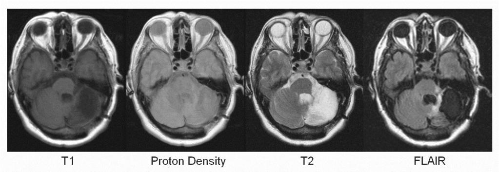
17 Contrast Mechanisms (T1, T2 and r) T1, Spin-Lattice Relaxation: Time taken for excited spins to relax back to ground state. White matter white, gray matter gray, CSF black. T2, Spin-Spin Relaxation: Time taken for excited spins to relax from ordered to disordered state. White matter black, gray matter gray, CSF white. r, Proton Density: # of (fluidic) protons/unit volume Contrast intermediate, with solids such as bone appearing black. 17


18 Image Contrast - Proton Density and T2 I z (t) ~ r e t/t2 {1- e t/t1 } TR/TE: 2000/25 TR/TE: 2000/50 TR/TE: 2000/75 TR/TE: 2000/100 TR/TE: 2000/150 TR/TE: 2000/200 18


19 Generation of T1-wtd images T1-weighted Signal Intensity WM Contrast-enhanced TR/TE: 120/20 TR/TE: 240/20 GM CSF TR/TE: 500/20 TR/TE: 1000/ TR (msec) TR/TE: 2000/20 TR/TE: 4000/20


20 Effect of TE/TR on visualizing pathology TR/TE: 600/20ms TR/TE: 2000/30ms TR/TE: 2000/90ms

21 T1, T2 of Different Tissues
22 Inversion Recovery Measurement of T 1 Z +M 0 Z +M 0 Fat Muscle Y Fluid, CSF Time X -M 0 X -M 0 M z (t) ~ M 0 (t){1- e t/t1 } RF Echo 180 o TI, Inversion Time 90 o TE/2 180 o TE/2 STIR, Fat suppression FLAIR Inversion Recovery: First tip by 180 o, then let decay (longitudinally) for TI (~300ms) Then add on a standard spin echo (90 o o ). Can repeat for several TI s. Curve of spin echo heights will give T1 values. Images are heaviy T1-weighted.
23 Enhanced Contrast: Gadolinium-DTPA: T1 contrast enhancement by IV injection of exogenous contrast agent. (Image: 14 yr. Old HIV patient). lesion Inversion Recovery (IR): Maximization of T1 contrast by special pulse sequence. (Image: Normal Brain). Fluid Attenuated IR (FLAIR): Suppression of bright CSF in T2- wtd. image to better visualize periventricular lesions. (Image: 14 yr. Old HIV patient). lesion
24 Magnetic Field Gradients : If the two vials are in same magnetic field, B 0, they both resonate at: w 0 = g*b 0 since they are in the same magnetic field They produce FID s at the same frequency. If the magnetic field is made to vary linearly along the X-axis as: B(x) = B 0 + (db/dx)* x, and, in frequency, w(x) = g*{b 0 +(db/dx)*x} = w 0 + g*(db/dx)*x, Then frequency of spin becomes dependent on it s X-spatial coordinate. Signal becomes spatially encoded, and one has mapping! The spins in the two vials produce FID s at two different frequencies since they are in different magnetic fields Similar gradients can be switched on each of the 3 physical axis's, to encode in all three directions.
25 Fourier Transform: Domain Domain Data is collected conveniently in one domain (time). Then Fourier Transformed to a space where it is easier to analyze (Frequency) The two data are connected to (and can be obtained from) each other by the Fourier Integral. Examples: Sound Perception, Music uses FT Visual Perception: Cannot FT. Useful Concepts: Dt Dwell Time T N*Dt Acquisition Time.

26 Magnetic Gradient Fields G X B Z X G X B Z Y G X B Z Z w=gb RF/Echo Slice Frequency Phase
27 Slice Selection Gradients with RF on: B 0 Left Right Slice Select Gradient p/2 (90 o ) 180 o 90 o Slice Selection: Spins aligned along B 0 Superimpose Slice Select gradient, db/dx: Linear variation of mag nc field w/ one axis Switch on RF 90 0 pulse Spins only within a slice are flipped by 90 0 to the X-Y plane SSG also switched on during pulse, so that same spins are flipped over. RF Pulses Slice Select Gradient
*x i } High Thickness of Slice: Change spread or bandwidth of RF pulse")

28 Slice Selection: High Position of Slice: Change frequency of RF f i = g*(b 0 + (db/dx)*x i } High Thickness of Slice: Change spread or bandwidth of RF pulse Or, can change (db/dx) Thin Slice Low Signal Frequency Frequency Low Low B 0 in presence of S/I magnetic field gradient MR signal frequency MRI of the selected slice
29 Frequency Frequency A few quick questions on Slice Selection: Position of Slice: Thickness of Slice: RF Pulse F1 RF Pulse Higher Gradient Lower Gradient RF Pulse F2 Slice Position (x) Thicker Slice Slice Position (x) Thicker Slice 1) At 1.5T, if Slice Thickness 10 to 5 mm, Gradient Strength? If Magnetic Field 1.5T 3T, for same change in Sl.Thk, Grad Strength? If Magnetic Field 1.5T 3T, how much will frequency need to be changed if going from left ear to right? For (i), what if changing from H nuclei to P?
30 B 0 Phase Encoding Gradient: Anterior q 1 q 2 q 3 q 1 q 2 Phase Encoding: For the spins selected by the SS The phase encoding gradient, db/dz, switched on for a short time Spins in different layers along the Z axis, rotated at different speeds, for the SAME time, Posterior q o But to different angles, q 1,q 2, q 3 These phase differences, or encoding, by which the spins are tapped, are remembered till the signal is finally detected. Is finally used in the Fourier Transform 90 o RF Pulses Phase Encoding Gradient
31 Read-Out Gradient: B 0 Superior f 1 f 2 f 3 f 4 f 1 f 3 Last gradient, db/dy, to be switched on, along the final, Y-axis. During detection of signal. Signal from each vertical slab, is at a different frequency, f 1, f 3, f 5. Inferior f o f 5 since they are in different magnetic field Final signal is a convulation of all these different frequencies, with phase differences from PE, and from protons selected by SS. 90 o RF Pulses Read-Out Gradient Echo
32 2D FT and Image Formation: TR Ech Ech o o 180 o 90 o 180 o Ech o Each such X-axis raw spectra, a projection of the Y-column. 90 o 180 o TE Has to be repeated 128~256 times Once entire column for each X-cord collected, a 2 nd FT along Y-axis yields Y- axis information. Total Scan Time = N pe * TR*N avg


 Only center of K-space Contrast of image (C) Outer lines")
33 K-Space Reciprocality with Physical Image Space: (A) (B) (C) FT of k-space data yield MR images. Different parts of k-space influence appearance of MR image in different ways. (A) FT of entire K-space Image w/ good contrast and resolution. (B) Only center of K-space Contrast of image (C) Outer lines Spatial resolution information, edges and contours of organs and other minute structures.
Only central lines Contrast (longwavelength) (C)Outer Lines")
34 FT of K-Space to Physical Space 2 nd Example: K-Space Data (A)All points included (B)Only central lines Contrast (longwavelength) (C)Outer Lines Edges

35 Reducing Scan Time Lower # of PE levels: Reduce # of PE levels: Reduce the total range of PE levels, Symmetric about zero Increment between levels remain the same. Zero-fill to original matrix size. Reduces total scan time: By 256xTR to 192xTR to 128xTR, FOV remains the same since, zero filled to original matrix size Resolution along PE direction, reduces in the ratio of 1:0.75::0.5 Resl n along RO remains same./ Downside: Possible Wrap-Around

 artifact 192x256 matrix 256x256 matrix 512x256 matrix 256x32 matrix 256x64")
36 Effect of Image Matrix Steps on SNR & Image Quality: 32x256 matrix 64x256 matrix 128x256 matrix FAST Spin Echo # of PE most important Improves in-plane spatial resolution in PE direction Increases total imaging time Decreases voxel volume Decreases SNR per voxel Decreases extent of truncation (Gibb s) artifact 192x256 matrix 256x256 matrix 512x256 matrix 256x32 matrix 256x64 matrix 256x128 matrix


37 Wrap Around Artifact -- Phase Direction: Number of Phase Encoding Steps: Each PE step takes TR amount of time. Larger the number of PE steps, better the resolution in that direction But, increases the total scan time. WRAP-AROUND ARTIFACT: If sufficient number of steps not acquired to cover range of anatomy along that direction Can be eliminated by increasing # of PE steps, Can change PE/RO directions to minimize effects. No Wrap Around Wrap Around Artifact


38 Motion Artifact Phase Direction: Motion Artifact: Since each PE line takes TR amount of time, Anatomy can be in different positions Physiologic Motions Motion artifacts registered along PE line. Can be eliminated by: Short scan time, Switch axis, Gating: Cardiac, Respiratory
 artifact N pe = 192 N pe = 256 N pe =")
39 Effect of Phase Encoding Steps on SNR and Image Quality: T1W: SE 500/26 ms N pe = 32 N pe = 64 N pe = 128 # of PE most important Improves in-plane spatial resolution in PE direction Increases total imaging time Decreases voxel volume Decreases SNR per voxel Decreases extent of truncation (Gibb s) artifact N pe = 192 N pe = 256 N pe = 512


40 15 cm FOV Effect of Changing FOV, w/ matrix constant: 60 cm FOV 50 cm FOV 40 cm FOV 30 cm FOV 25 cm FOV 20 cm FOV 10 cm FOV Matrix size is kept constant at 256x256: As FOV is decreased: Spatial resolution increases due to smaller voxel dimensions in both inplane directions, SNR per voxel decreases due to smaller voxels Aliasing (wraparound) artifacts begins to occur when signal producing material is outside FOV in the PE direction Can be eliminated by over-sampling SNR increases as square of FOV

41 Effect of Bandwidth on SNR & Image Quality: BW = 2.2 KHz BW = 7.8 KHz BW = 2.2 KHz BW = 3.9 KHz BW = 15.6 KHz BW = 3.9 KHz Bandwidth (BW) Range of frequencies that the receiver system accepts. As BW is increased, range of frequencies over which signal is received is increased. While signal remains constant, noise increases as square-root of BW. As BW is increased, total duration of signal sampling and dwell time are decreased inversely. To keep FOV in RO direction unchanged, as BW in increased, RO gradient amplitude has to be increased. Chemical shift artifact decreases w/ BW increase. Fig. E and F, show inhomogeneties at low BW, (E), which disappear at higher BW (F). In EPI, BW is increase by order of magnitude.


42 Effect of Slice Thickness on SNR and Image Quality: Slice Thk: 3 mm Slice Thk: 5 mm Slice Thk: 7 mm Signal is proportional to # of protons/ voxel As Sl.thk. Increases, # of protons increases linearly w/ Sl.Thk Partial voluming also increases w/ Sl.Thk. Thinner slices always preferred: since better resolution, Limited by SNR, and gradients. Slice Thk: 10 mm Slice Thk: 15 mm Slice Thk: 20 mm
43 Imaging and Pulse Sequences: D 53: E. Spin Echo Imaging: Echoes generated by a 180o RF. D 54: D. Gradient Echo Imaging: Typical flip angles of 10~40o. D 55: A. 2-D FT has PE. in one direction and RO in other. D 56: B. 3-D FT has PE in both original PE and SS directions, and RO in the 3 rd. D53: C. (1.0T/1.5T)*64= 40 MHz. D54: D. Decreasing slice thickness decreases # of protons creating signal, hence decreases SNR.
44 Contrast: D51: C. Long T1 tends to saturate and short T2 decays the signal too rapidly. Higher signals are produced from short T1 and long T2. D 52: D. T1 ~80 to 3000ms; T2 ~ 10 to 80ms. T2* is reduced from T2. D55: E. Atomic number doesn t play a part. D 56: A. Pure water has a long T1 and long T2, same as CSF. Both can be shortened by D57: C. Gradient fields are used to localize MR signal. D 58: B. RF pulses are used to flip M thru desired angles. D59: A. Shim coils are used to change magnetic fields locally and increase inhomogeneity of field.
45 Artifacts: D57: A. Chemical Shift from differences in resonant frequency of different types of protons.; Zipper Artifact: Typically from motion or Electronic noise; Wrap-around from less # of PE levels. Ring artifact from Gibb s ringing.


46 K-Space Traversal: Standard Spin Echo Standard Spin Echo FAST Spin Echo HASTE Standard Spin Echo Sequence: One line of K-space per TR collected. Sequence repeated to cover K-space. EPI acquires multiple segments of image data from a single SE or GE. Oscillating gradient fast acquisition techniques. Snapshot EPI Acquisition that collects all PE levels from a single echo train.
; Ryf (2004); 3) DENSE: Aletras (1999); 4) Single shot VE-PC Spiral, Asakawa (2003). 5) Fig.")


47 A little bit of Physics (Spin Tags, Spirals etc ) A B C D Ref: 1) VE-PC: Drace (1994); Sinha (2004); 2) Spin Tag: Axel (1989); Ryf (2004); 3) DENSE: Aletras (1999); 4) Single shot VE-PC Spiral, Asakawa (2003). 5) Fig. Bernstein s A. Rectilinear: 1 PE line per R-R interval 128~80 contractions Most dense sampling; higher resolution. B. Spiral Coverage less dense, corners not sampled E F C. Single Spiral: Can cover entire K-space in 1 R-R. Very rapid but low res. D. Interleaved Spirals: N- arms, denser sampling, higher res, but N R-R intervals. E: SPAMM and DANTE RF pulse for producing spin tags F. Spiral Gradient Waveform Combined by us with Spiral Acquisition.


48 Partial Fourier Imaging: Half-Fourier Sampling 3/4-Fourier Sampling Full-Fourier Sampling Partial Fourier Imaging: Collects only part of FID, Does not reduce Image Matrix or Field of View Can be either in PE or RO direction In PE directions, reduces Total Scan Time drastically Generate remaining data by symmetry Save significant time, but Increases artifact In RO direction, can reduce TE
49 Enhanced Contrast: Gadolinium-DTPA: T1 contrast enhancement by IV injection of exogenous contrast agent. (Image: 14 yr. Old HIV patient). lesion Inversion Recovery (IR): Maximization of T1 contrast by special pulse sequence. (Image: Normal Brain). Fluid Attenuated IR (FLAIR): Suppression of bright CSF in T2- wtd. image to better visualize periventricular lesions. (Image: 14 yr. Old HIV patient). lesion 49
 spins")

 Magnitude image, (b) corresponding phase image")
, (C)")
50 Contrast from Flow MR Angiography: Utilizes inherent differences in contrast between flowing (blood) spins and stationary tissue. Time-of-Flight MRA: For Visualization of Vasculature. Phase Contrast MRA: Quantifies flow/velocity. (a) Magnitude image, (b) corresponding phase image (note that flow in opposite directions has different signs as in the ascending and descending aorta), (C) velocity profile across aorta reveals laminar flow. 50
51 Phase Accumulated by Moving Spins Distance moved in time dt Phase of Spin Phase acquired by Spin proportional to: 1) Velocity, 2) Gradient (VENC) F 2 F 1 -F 1 Phase difference of moving spins prop. to bipolar gradient strength, duration & separation: These factors define flow sensitivity (venc ) venc should exceed max. velocity in image: o If not, white pixels wrap around as black pixels and vice-versa o If venc too high, vessels not visualized well, overall SNR decreases o Imp. to optimize venc (value close to maximum anticipated vessel velocity) 51
52 2D Time-of-Flight- Principle Based on in-flow enhancement Max enhancement vessel perp. to imaging plane SI of in-flowing blood high, SI of stationary tissue saturated (TR < T1 of tissue) 52
 are shown at the level of the carotids")
53 Raw Data Set 6 directly acquired images (out of 256) are shown at the level of the carotids 53

54 Post-Processing: MIP Stack of axial slices typically from 2D-TOF or stack of slabs from 3D volume subjected to ray-tracing technique: maximum intensity projections filters strong vascular signals from volume and projects to a single plane brightest voxel is selected along a given direction multiple projection images of the vessels along the slice axis 54


")
55 & After MIP MIP images in different projections: axial (a), sagittal (b) and coronal (c) 55
56 Phase Contrast MRA RF G z G x G v One image without additional velocity encoding One image with additional velocity encoding Display phase difference between images Phase difference is directly proportional to velocity Phase difference subtracts out off-resonance and other phase effects 56


57 Phase Contrast MRA Phase is proportional to velocity Quantitate velocity from phase images and/or: Construct angiograms by MIP of velocity maps MIP 57
Introduction to MRI. Spin & Magnetic Moments. Relaxation (T1, T2) Spin Echoes. 2DFT Imaging. K-space & Spatial Resolution.
 Spin Echoes. 2DFT Imaging. K-space & Spatial Resolution.") Introduction to MRI Spin & Magnetic Moments Relaxation (T1, T2) Spin Echoes 2DFT Imaging Selective excitation, phase & frequency encoding K-space & Spatial Resolution Contrast (T1, T2) Acknowledgement:
Introduction to MRI Spin & Magnetic Moments Relaxation (T1, T2) Spin Echoes 2DFT Imaging Selective excitation, phase & frequency encoding K-space & Spatial Resolution Contrast (T1, T2) Acknowledgement:
Introduction to Biomedical Imaging
 Alejandro Frangi, PhD Computational Imaging Lab Department of Information & Communication Technology Pompeu Fabra University www.cilab.upf.edu MRI advantages Superior soft-tissue contrast Depends on among
MRI in Review: Simple Steps to Cutting Edge Part I
 MRI in Review: Simple Steps to Cutting Edge Part I DWI is now 2 years old... Mike Moseley Radiology Stanford DWI, b = 1413 T2wt, 28/16 ASN 21 San Francisco + Disclosures: Funding NINDS, NCRR, NCI 45 minutes
Physics of MR Image Acquisition
 Physics of MR Image Acquisition HST-583, Fall 2002 Review: -MRI: Overview - MRI: Spatial Encoding MRI Contrast: Basic sequences - Gradient Echo - Spin Echo - Inversion Recovery : Functional Magnetic Resonance
MRI Physics I: Spins, Excitation, Relaxation
 MRI Physics I: Spins, Excitation, Relaxation Douglas C. Noll Biomedical Engineering University of Michigan Michigan Functional MRI Laboratory Outline Introduction to Nuclear Magnetic Resonance Imaging
Part III: Sequences and Contrast
 Part III: Sequences and Contrast Contents T1 and T2/T2* Relaxation Contrast of Imaging Sequences T1 weighting T2/T2* weighting Contrast Agents Saturation Inversion Recovery JUST WATER? (i.e., proton density
MRI in Practice. Catherine Westbrook MSc, DCRR, CTC Senior Lecturer Anglia Polytechnic University Cambridge UK. John Talbot MSc, DCRR
 MRI in Practice Third edition Catherine Westbrook MSc, DCRR, CTC Senior Lecturer Anglia Polytechnic University Cambridge UK and Carolyn Kaut RothRT(R) (MR) (CT) (M) (CV) Fellow SMRT (Section for Magnetic
Chapter 24 MRA and Flow quantification. Yongquan Ye, Ph.D. Assist. Prof. Radiology, SOM Wayne State University
 Chapter 24 MRA and Flow quantification Yongquan Ye, Ph.D. Assist. Prof. Radiology, SOM Wayne State University Previous classes Flow and flow compensation (Chap. 23) Steady state signal (Cha. 18) Today
Fundamental MRI Principles Module Two
 Fundamental MRI Principles Module Two 1 Nuclear Magnetic Resonance There are three main subatomic particles: protons neutrons electrons positively charged no significant charge negatively charged Protons
Contrast Mechanisms in MRI. Michael Jay Schillaci
 Contrast Mechanisms in MRI Michael Jay Schillaci Overview Image Acquisition Basic Pulse Sequences Unwrapping K-Space Image Optimization Contrast Mechanisms Static and Motion Contrasts T1 & T2 Weighting,
NMR and MRI : an introduction
 Intensive Programme 2011 Design, Synthesis and Validation of Imaging Probes NMR and MRI : an introduction Walter Dastrù Università di Torino walter.dastru@unito.it \ Introduction Magnetic Resonance Imaging
MR Advance Techniques. Flow Phenomena. Class I
 MR Advance Techniques Flow Phenomena Class I Flow Phenomena In this class we will explore different phenomenona produced from nuclei that move during the acquisition of data. Flowing nuclei exhibit different
FREQUENCY SELECTIVE EXCITATION
 PULSE SEQUENCES FREQUENCY SELECTIVE EXCITATION RF Grad 0 Sir Peter Mansfield A 1D IMAGE Field Strength / Frequency Position FOURIER PROJECTIONS MR Image Raw Data FFT of Raw Data BACK PROJECTION Image Domain
Introductory MRI Physics
 C HAPR 18 Introductory MRI Physics Aaron Sodickson EXRNAL MAGNETIC FIELD, PROTONS AND EQUILIBRIUM MAGNETIZATION Much of the bulk of the magnetic resonance imaging (MRI) scanner apparatus is dedicated to
Fundamental MRI Principles Module 2 N. Nuclear Magnetic Resonance. X-ray. MRI Hydrogen Protons. Page 1. Electrons
 Fundamental MRI Principles Module 2 N S 1 Nuclear Magnetic Resonance There are three main subatomic particles: protons positively charged neutrons no significant charge electrons negatively charged Protons
The NMR Inverse Imaging Problem
 The NMR Inverse Imaging Problem Nuclear Magnetic Resonance Protons and Neutrons have intrinsic angular momentum Atoms with an odd number of proton and/or odd number of neutrons have a net magnetic moment=>
Introduction to Magnetic Resonance Imaging (MRI) Pietro Gori
 Pietro Gori") Introduction to Magnetic Resonance Imaging (MRI) Pietro Gori Enseignant-chercheur Equipe IMAGES - Télécom ParisTech pietro.gori@telecom-paristech.fr September 20, 2017 P. Gori BIOMED 20/09/2017 1 / 76
Introduction to Magnetic Resonance Imaging (MRI) Pietro Gori Enseignant-chercheur Equipe IMAGES - Télécom ParisTech pietro.gori@telecom-paristech.fr September 20, 2017 P. Gori BIOMED 20/09/2017 1 / 76
Basis of MRI Contrast
 Basis of MRI Contrast MARK A. HORSFIELD Department of Cardiovascular Sciences University of Leicester Leicester LE1 5WW UK Tel: +44-116-2585080 Fax: +44-870-7053111 e-mail: mah5@le.ac.uk 1 1.1 The Magnetic
EL-GY 6813/BE-GY 6203 Medical Imaging, Fall 2016 Final Exam
 EL-GY 6813/BE-GY 6203 Medical Imaging, Fall 2016 Final Exam (closed book, 1 sheets of notes double sided allowed, no calculator or other electronic devices allowed) 1. Ultrasound Physics (15 pt) A) (9
Outlines: (June 11, 1996) Instructor:
 Instructor:") Magnetic Resonance Imaging (June 11, 1996) Instructor: Tai-huang Huang Institute of Biomedical Sciences Academia Sinica Tel. (02) 2652-3036; Fax. (02) 2788-7641 E. mail: bmthh@ibms.sinica.edu.tw Reference:
Magnetic Resonance Imaging (June 11, 1996) Instructor: Tai-huang Huang Institute of Biomedical Sciences Academia Sinica Tel. (02) 2652-3036; Fax. (02) 2788-7641 E. mail: bmthh@ibms.sinica.edu.tw Reference:
Rad Tech 4912 MRI Registry Review. Outline of the Registry Exam: Certification Fees
 Rad Tech 4912 MRI Registry Review Outline of the Registry Exam: Category: # of questions: A. Patient Care 30 B. Imaging Procedures 62 C. Data Acquisition and Processing 65 D. Physical Principles of Image
Magnetic Resonance Imaging. Pål Erik Goa Associate Professor in Medical Imaging Dept. of Physics
 Magnetic Resonance Imaging Pål Erik Goa Associate Professor in Medical Imaging Dept. of Physics pal.e.goa@ntnu.no 1 Why MRI? X-ray/CT: Great for bone structures and high spatial resolution Not so great
Field trip: Tuesday, Feb 5th
 Pulse Sequences Field trip: Tuesday, Feb 5th Hardware tour of VUIIIS Philips 3T Meet here at regular class time (11.15) Complete MRI screening form! Chuck Nockowski Philips Service Engineer Reminder: Project/Presentation
Background II. Signal-to-Noise Ratio (SNR) Pulse Sequences Sampling and Trajectories Parallel Imaging. B.Hargreaves - RAD 229.
 Pulse Sequences Sampling and Trajectories Parallel Imaging. B.Hargreaves - RAD 229.") Background II Signal-to-Noise Ratio (SNR) Pulse Sequences Sampling and Trajectories Parallel Imaging 1 SNR: Signal-to-Noise Ratio Signal: Desired voltage in coil Noise: Thermal, electronic Noise Thermal
Background II Signal-to-Noise Ratio (SNR) Pulse Sequences Sampling and Trajectories Parallel Imaging 1 SNR: Signal-to-Noise Ratio Signal: Desired voltage in coil Noise: Thermal, electronic Noise Thermal
The Basics of Magnetic Resonance Imaging
 The Basics of Magnetic Resonance Imaging Nathalie JUST, PhD nathalie.just@epfl.ch CIBM-AIT, EPFL Course 2013-2014-Chemistry 1 Course 2013-2014-Chemistry 2 MRI: Many different contrasts Proton density T1
Tissue Characteristics Module Three
 Tissue Characteristics Module Three 1 Equilibrium State Equilibrium State At equilibrium, the hydrogen vector is oriented in a direction parallel to the main magnetic field. Hydrogen atoms within the vector
Basic MRI physics and Functional MRI
 Basic MRI physics and Functional MRI Gregory R. Lee, Ph.D Assistant Professor, Department of Radiology June 24, 2013 Pediatric Neuroimaging Research Consortium Objectives Neuroimaging Overview MR Physics
Chapter 14:Physics of Magnetic Resonance
 Chapter 14:Physics of Magnetic Resonance Slide set of 141 slides based on the chapter authored by Hee Kwon Song of the publication (ISBN 978-92-0-131010-1): Diagnostic Radiology Physics: A Handbook for
Principles of Magnetic Resonance Imaging
 Principles of Magnetic Resonance Imaging Hi Klaus Scheffler, PhD Radiological Physics University of 1 Biomedical Magnetic Resonance: 1 Introduction Magnetic Resonance Imaging Contents: Hi 1 Introduction
NMR/MRI examination (8N080 / 3F240)
") NMR/MRI examination (8N080 / 3F240) Remarks: 1. This test consists of 3 problems with at total of 26 sub-questions. 2. Questions are in English. You are allowed to answer them in English or Dutch. 3. Please
NMR/MRI examination (8N080 / 3F240) Remarks: 1. This test consists of 3 problems with at total of 26 sub-questions. 2. Questions are in English. You are allowed to answer them in English or Dutch. 3. Please
Basic Pulse Sequences I Saturation & Inversion Recovery UCLA. Radiology
 Basic Pulse Sequences I Saturation & Inversion Recovery Lecture #5 Learning Objectives Explain what the most important equations of motion are for describing spin systems for MRI. Understand the assumptions
G Medical Imaging. Outline 4/13/2012. Physics of Magnetic Resonance Imaging
 G16.4426 Medical Imaging Physics of Magnetic Resonance Imaging Riccardo Lattanzi, Ph.D. Assistant Professor Department of Radiology, NYU School of Medicine Department of Electrical and Computer Engineering,
Nuclei, Excitation, Relaxation
 Outline 4.1 Principles of MRI uclei, Excitation, Relaxation Carolyn Kaut Roth, RT (R)(MR)(CT)(M)(CV) FSMRT CEO Imaging Education Associates www.imaginged.com candi@imaginged.com What nuclei are MR active?
Nuclear Magnetic Resonance Imaging
 Nuclear Magnetic Resonance Imaging Jeffrey A. Fessler EECS Department The University of Michigan NSS-MIC: Fundamentals of Medical Imaging Oct. 20, 2003 NMR-0 Background Basic physics 4 magnetic fields
On Signal to Noise Ratio Tradeoffs in fmri
 On Signal to Noise Ratio Tradeoffs in fmri G. H. Glover April 11, 1999 This monograph addresses the question of signal to noise ratio (SNR) in fmri scanning, when parameters are changed under conditions
Sequence Overview. Gradient Echo Spin Echo Magnetization Preparation Sampling and Trajectories Parallel Imaging. B.Hargreaves - RAD 229
 Sequence Overview Gradient Echo Spin Echo Magnetization Preparation Sampling and Trajectories Parallel Imaging 75 Pulse Sequences and k-space RF k y G z k x G x 3D k-space G y k y k z Acq. k x 76 Gradient
Nuclear Magnetic Resonance Imaging
 Nuclear Magnetic Resonance Imaging Simon Lacoste-Julien Electromagnetic Theory Project 198-562B Department of Physics McGill University April 21 2003 Abstract This paper gives an elementary introduction
MRI Physics II: Gradients, Imaging. Douglas C. Noll, Ph.D. Dept. of Biomedical Engineering University of Michigan, Ann Arbor
 MRI Physics II: Gradients, Imaging Douglas C., Ph.D. Dept. of Biomedical Engineering University of Michigan, Ann Arbor Magnetic Fields in MRI B 0 The main magnetic field. Always on (0.5-7 T) Magnetizes
EE225E/BIOE265 Spring 2013 Principles of MRI. Assignment 9 Solutions. Due April 29th, 2013
 EE5E/BIOE65 Spring 013 Principles of MRI Miki Lustig This is the last homework in class. Enjoy it. Assignment 9 Solutions Due April 9th, 013 1) In class when we presented the spin-echo saturation recovery
M R I Physics Course. Jerry Allison Ph.D., Chris Wright B.S., Tom Lavin B.S., Nathan Yanasak Ph.D. Department of Radiology Medical College of Georgia
 M R I Physics Course Jerry Allison Ph.D., Chris Wright B.S., Tom Lavin B.S., Nathan Yanasak Ph.D. Department of Radiology Medical College of Georgia M R I Physics Course Spin Echo Imaging Hahn Spin Echo
The physics US and MRI. Prof. Peter Bogner
 The physics US and MRI Prof. Peter Bogner Sound waves mechanical disturbance, a pressure wave moves along longitudinal wave compression rarefaction zones c = nl, (c: velocity, n: frequency, l: wavelength
Introduction to the Physics of NMR, MRI, BOLD fmri
 Pittsburgh, June 13-17, 2011 Introduction to the Physics of NMR, MRI, BOLD fmri (with an orientation toward the practical aspects of data acquisition) Pittsburgh, June 13-17, 2001 Functional MRI in Clinical
Velocity Images. Phase Contrast Technique. G. Reiter 1,2, U. Reiter 1, R. Rienmüller 1
 Velocity Images - the MR Phase Contrast Technique G. Reiter 1,2, U. Reiter 1, R. Rienmüller 1 SSIP 2004 12 th Summer School in Image Processing, Graz, Austria 1 Interdisciplinary Cardiac Imaging Center,
Magnetization Preparation Sequences
 Magnetization Preparation Sequences Acquisition method may not give desired contrast Prep block adds contrast (and/or encoding) MP-RAGE = Magnetization prepared rapid acquisition with gradient echo (Mugler,
K-space. Spin-Warp Pulse Sequence. At each point in time, the received signal is the Fourier transform of the object s(t) = M( k x
 = M( k x") Bioengineering 280A Principles of Biomedical Imaging Fall Quarter 2015 MRI Lecture 4 k (t) = γ 2π k y (t) = γ 2π K-space At each point in time, the received signal is the Fourier transform of the object
Bioengineering 280A Principles of Biomedical Imaging Fall Quarter 2015 MRI Lecture 4 k (t) = γ 2π k y (t) = γ 2π K-space At each point in time, the received signal is the Fourier transform of the object
RADIOLOGIV TECHNOLOGY 4912 COMPREHENSEIVE REVIEW/MRI WORSHEET #1- PATIENT CARE AND SAFETY/PHYSICAL PRINCIPLES
 RADIOLOGIV TECHNOLOGY 4912 COMPREHENSEIVE REVIEW/MRI WORSHEET #1- PATIENT CARE AND SAFETY/PHYSICAL PRINCIPLES 1. What are potential consequences to patients and personnel should there be a release of gaseous
The physics of medical imaging US, CT, MRI. Prof. Peter Bogner
 The physics of medical imaging US, CT, MRI Prof. Peter Bogner Clinical radiology curriculum blocks of lectures and clinical practice (7x2) Physics of medical imaging Neuroradiology Head and neck I. Head
Basic p rinciples COPYRIGHTED MATERIAL. Introduction. Atomic s tructure
 1 Basic p rinciples Introduction 1 Atomic structure 1 Motion in the atom 2 MR active nuclei 2 The hydrogen nucleus 4 Alignment 4 Precession 8 The Larmor equation 9 Introduction The basic principles of
Biomedical Imaging Magnetic Resonance Imaging
 Biomedical Imaging Magnetic Resonance Imaging Charles A. DiMarzio & Eric Kercher EECE 4649 Northeastern University May 2018 Background and History Measurement of Nuclear Spins Widely used in physics/chemistry
Lab 2: Magnetic Resonance Imaging
 EE225E/BIOE265 Spring 2013 Principles of MRI Miki Lustig Developed by: Galen Reed and Miki Lustig Lab 2: Magnetic Resonance Imaging Introduction In this lab, we will get some hands-on experience with an
MRI at a Glance. Blackwell Science CATHERINE WESTBROOK. MSC DCRR CTC Director of Training and Education Lodestone Patient Care Ltd
 MRI at a Glance MRI at a Glance CATHERINE WESTBROOK MSC DCRR CTC Director of Training and Education Lodestone Patient Care Ltd Blackwell Science 2002 by Blackwell Science Ltd, a Blackwell Publishing Company
BASIC MRI PHYSICS SPIN GYMNASTICS Don Plewes PhD, Walter Kucharczyk MD
 BASIC MRI PHYSICS SPIN GYMNASTICS Don Plewes PhD, Walter Kucharczyk MD Introduction To understand MRI, it is first necessary to understand the physics of proton Nuclear Magnetic Resonance (NMR). The most
Basic Pulse Sequences II - Spin Echoes. TE=12ms TE=47ms TE=106ms TE=153ms UCLA. Radiology
 TE TR 90 180 90 Basic Pulse Sequences II - Spin Echoes TE=12ms TE=47ms TE=106ms TE=153ms TE=235ms Lecture #6 Summary B1(t) RF TR RF t ~M (1) (0 )= ~ M 0 = 2 4 0 0 M 0 3 5 Initial Condition ~M (1) (0 +
Apodization. Gibbs Artifact. Bioengineering 280A Principles of Biomedical Imaging. Fall Quarter 2013 MRI Lecture 5. rect(k x )
") Bioengineering 280A Principles of Biomedical Imaging Fall Quarter 2013 MRI Lecture 5 GE Medical Systems 2003 Gibbs Artifact Apodization rect(k ) Hanning Window h(k )=1/2(1+cos(2πk ) 256256 image 256128
Bioengineering 280A Principles of Biomedical Imaging Fall Quarter 2013 MRI Lecture 5 GE Medical Systems 2003 Gibbs Artifact Apodization rect(k ) Hanning Window h(k )=1/2(1+cos(2πk ) 256256 image 256128
Pulse Sequences: RARE and Simulations
 Pulse Sequences: RARE and Simulations M229 Advanced Topics in MRI Holden H. Wu, Ph.D. 2018.04.19 Department of Radiological Sciences David Geffen School of Medicine at UCLA Class Business Final project
Cambridge University Press MRI from A to Z: A Definitive Guide for Medical Professionals Gary Liney Excerpt More information
 Main glossary Aa AB systems Referring to molecules exhibiting multiply split MRS peaks due to spin-spin interactions. In an AB system, the chemical shift between the spins is of similar magnitude to the
BMB 601 MRI. Ari Borthakur, PhD. Assistant Professor, Department of Radiology Associate Director, Center for Magnetic Resonance & Optical Imaging
 BMB 601 MRI Ari Borthakur, PhD Assistant Professor, Department of Radiology Associate Director, Center for Magnetic Resonance & Optical Imaging University of Pennsylvania School of Medicine A brief history
Tissue Parametric Mapping:
 Tissue Parametric Mapping: Contrast Mechanisms Using SSFP Sequences Jongho Lee Department of Radiology University of Pennsylvania Tissue Parametric Mapping: Contrast Mechanisms Using bssfp Sequences Jongho
Midterm Review. EE369B Concepts Simulations with Bloch Matrices, EPG Gradient-Echo Methods. B.Hargreaves - RAD 229
 Midterm Review EE369B Concepts Simulations with Bloch Matrices, EPG Gradient-Echo Methods 292 Fourier Encoding and Reconstruction Encoding k y x Sum over image k x Reconstruction k y Gradient-induced Phase
BNG/ECE 487 FINAL (W16)
") BNG/ECE 487 FINAL (W16) NAME: 4 Problems for 100 pts This exam is closed-everything (no notes, books, etc.). Calculators are permitted. Possibly useful formulas and tables are provided on this page. Fourier
BNG/ECE 487 FINAL (W16) NAME: 4 Problems for 100 pts This exam is closed-everything (no notes, books, etc.). Calculators are permitted. Possibly useful formulas and tables are provided on this page. Fourier
Lecture k-space. k-space illustrations. Zeugmatography 3/7/2011. Use of gradients to make an image echo. K-space Intro to k-space sampling
 Lecture 21-3-16 K-space Intro to k-space sampling (chap 3) Frequenc encoding and Discrete sampling (chap 2) Point Spread Function K-space properties K-space sampling principles (chap 3) Basic Contrast
Lecture 21. Nuclear magnetic resonance
 Lecture 21 Nuclear magnetic resonance A very brief history Stern and Gerlach atomic beam experiments Isidor Rabi molecular beam exp.; nuclear magnetic moments (angular momentum) Felix Bloch & Edward Purcell
Introduction to MRI Acquisition
 Introduction to MRI Acquisition James Meakin FMRIB Physics Group FSL Course, Bristol, September 2012 1 What are we trying to achieve? 2 What are we trying to achieve? Informed decision making: Protocols
Exam 8N080 - Introduction to MRI
 Exam 8N080 - Introduction to MRI Friday April 10 2015, 18.00-21.00 h For this exam you may use an ordinary calculator (not a graphical one). In total there are 5 assignments and a total of 50 points can
Bioengineering 278" Magnetic Resonance Imaging" " Winter 2011" Lecture 9! Time of Flight MRA!
 Bioengineering 278" Magnetic Resonance Imaging" " Winter 2011" Lecture 9 Motion Encoding using Longitudinal Magnetization: Magnetic Resonance Angiography Time of Flight Contrast Enhanced Arterial Spin
BME I5000: Biomedical Imaging
 BME I5000: Biomedical Imaging Lecture 9 Magnetic Resonance Imaging (imaging) Lucas C. Parra, parra@ccny.cuny.edu Blackboard: http://cityonline.ccny.cuny.edu/ 1 Schedule 1. Introduction, Spatial Resolution,
Topics. The concept of spin Precession of magnetic spin Relaxation Bloch Equation. Bioengineering 280A Principles of Biomedical Imaging
 Bioengineering 280A Principles of Biomedical Imaging Fall Quarter 2006 MRI Lecture 1 Topics The concept of spin Precession of magnetic spin Relaxation Bloch Equation 1 Spin Intrinsic angular momentum of
The Physical Basis of Nuclear Magnetic Resonance Part I ESMRMB. Jürgen R. Reichenbach
 The Physical Basis of Nuclear agnetic Resonance Part I Jürgen R. Reichenbach odule 1 October 17, 216 Outline of odule Introduction Spin and magnetic moment Spin precession, Larmor frequency agnetic properties
Relaxation times in nuclear magnetic resonance
 Relaxation times in TEP Related topics Nuclear spins, atomic nuclei with a magnetic moment, precession movement of the nuclear spins, Landau-Lifshitz equation, Bloch equation, magnetisation, resonance
Physical fundamentals of magnetic resonance imaging
 Physical fundamentals of magnetic resonance imaging Stepan Sereda University of Bonn 1 / 26 Why? Figure 1 : Full body MRI scan (Source: [4]) 2 / 26 Overview Spin angular momentum Rotating frame and interaction
Magnetic Resonance Imaging in a Nutshell
 Magnetic Resonance Imaging in a Nutshell Oliver Bieri, PhD Department of Radiology, Division of Radiological Physics, University Hospital Basel Department of Biomedical Engineering, University of Basel,
A Study of Flow Effects on the Gradient Echo Sequence
 -MR Flow Imaging- A Study of Flow Effects on the Gradient Echo Sequence Cylinder filled with doped water α pulse α pulse Flowing water Plastic pipes Slice Phase Read a TE b Signal sampling TR Thesis for
Index. p, lip, 78 8 function, 107 v, 7-8 w, 7-8 i,7-8 sine, 43 Bo,94-96
 p, lip, 78 8 function, 107 v, 7-8 w, 7-8 i,7-8 sine, 43 Bo,94-96 B 1,94-96 M,94-96 B oro!' 94-96 BIro!' 94-96 I/r, 79 2D linear system, 56 2D FFT, 119 2D Fourier transform, 1, 12, 18,91 2D sinc, 107, 112
Introduction to the Course and the Techniques. Jeffry R. Alger, PhD Ahmanson-Lovelace Brain Mapping Center Department of Neurology
 Introduction to the Course and the Techniques Jeffry R. Alger, PhD Ahmanson-Lovelace Brain Mapping Center Department of Neurology (jralger@ucla.edu) CTSI Neuroimaging April 2013 Rationale for the Course
2.1.1 A Brief History of NMR The conception of NMR sprouted after the Pauli s prediction of nuclear spin in
 CHAPTER--2 BASICS OF NMR IMAGING AND SPECTROSCOPY 2.1 Introduction 2.1.1 A Brief History of NMR The conception of NMR sprouted after the Pauli s prediction of nuclear spin in 1924. Later Gorter (1936)
Advanced Topics and Diffusion MRI
 Advanced Topics and Diffusion MRI Slides originally by Karla Miller, FMRIB Centre Modified by Mark Chiew (mark.chiew@ndcn.ox.ac.uk) Slides available at: http://users.fmrib.ox.ac.uk/~mchiew/teaching/ MRI
Correction Gradients. Nov7, Reference: Handbook of pulse sequence
 Correction Gradients Nov7, 2005 Reference: Handbook of pulse sequence Correction Gradients 1. Concomitant-Field Correction Gradients 2. Crusher Gradients 3. Eddy-Current Compensation 4. Spoiler Gradients
Magnetic Resonance Imaging (MRI)
") Magnetic Resonance Imaging Introduction The Components The Technology (MRI) Physics behind MR Most slides taken from http:// www.slideworld.org/ viewslides.aspx/magnetic- Resonance-Imaging- %28MRI%29-MR-Imaging-
Magnetic Resonance Imaging Introduction The Components The Technology (MRI) Physics behind MR Most slides taken from http:// www.slideworld.org/ viewslides.aspx/magnetic- Resonance-Imaging- %28MRI%29-MR-Imaging-
Chapter 7. Nuclear Magnetic Resonance Spectroscopy
 Chapter 7 Nuclear Magnetic Resonance Spectroscopy I. Introduction 1924, W. Pauli proposed that certain atomic nuclei have spin and magnetic moment and exposure to magnetic field would lead to energy level
M R I Physics Course
 M R I Physics Course Some Body Techniques/Protocols Nathan Yanasak, Ph.D. Jerry Allison, Ph.D. Tom Lavin, M.S. Department of Radiology Medical College of Georgia References: 1) The Physics of Clinical
Magnetic Resonance Imaging
 http://www.qldxray.com.au/filelibrary/mri_cardiovascular_system_ca_0005.jpg Magnetic Resonance Imaging 1 Overview 1. The magnetic properties of nuclei, and how they behave in strong magnetic fields. 2.
Sketch of the MRI Device
 Outline for Today 1. 2. 3. Introduction to MRI Quantum NMR and MRI in 0D Magnetization, m(x,t), in a Voxel Proton T1 Spin Relaxation in a Voxel Proton Density MRI in 1D MRI Case Study, and Caveat Sketch
Introduction to Magnetic Resonance Imaging
 Introduction to Magnetic Resonance Imaging MRI of the brain, ca. 1978. ca. 1993 ca. 2006 2014 Modality Characteristics and Comparison Radiography CT scanning Nuclear medicine MRI transmission modalities
Chemistry 431. Lecture 23
 Chemistry 431 Lecture 23 Introduction The Larmor Frequency The Bloch Equations Measuring T 1 : Inversion Recovery Measuring T 2 : the Spin Echo NC State University NMR spectroscopy The Nuclear Magnetic
Navigator Echoes. BioE 594 Advanced Topics in MRI Mauli. M. Modi. BioE /18/ What are Navigator Echoes?
 Navigator Echoes BioE 594 Advanced Topics in MRI Mauli. M. Modi. 1 What are Navigator Echoes? In order to correct the motional artifacts in Diffusion weighted MR images, a modified pulse sequence is proposed
Medical Imaging Physics Spring Quarter Week 9-1
 Medical Imaging Physics Spring Quarter Week 9-1 NMR and MRI Davor Balzar balzar@du.edu www.du.edu/~balzar Intro MRI Outline NMR & MRI Guest lecturer fmri Thursday, May 22 Visit to CUHSC It s not mandatory
} B 1 } Coil } Gradients } FFT
 Introduction to MRI Daniel B. Ennis, Ph.D. Requirements for MRI UCLA DCVI Requirements for MRI Dipoles to Images MR Active uclei e.g. 1 H in H20 Cryogen Liquid He and 2 Magnetic Field (B0) Polarizer ystem
Functional Magnetic Resonance Imaging (FMRI) is an imaging technique for
 is an imaging technique for") Chapter 2 Principles of FMRI Functional Magnetic Resonance Imaging (FMRI) is an imaging technique for examining brain function. Since its first appearance in 1991 (Belliveau et al.[8]) the use of FMRI
Chapter 2 Principles of FMRI Functional Magnetic Resonance Imaging (FMRI) is an imaging technique for examining brain function. Since its first appearance in 1991 (Belliveau et al.[8]) the use of FMRI
Spatial encoding in Magnetic Resonance Imaging. Jean-Marie BONNY
 Spatial encoding in Magnetic Resonance Imaging Jean-Marie BONNY What s Qu est an image ce qu une? image? «a reproduction of a material object by a camera or a related technique» Multi-dimensional signal
Overview Optimizing MR Imaging Procedures:
 Overview Optimizing MR Imaging Procedures: The Physicist as a Consultant Lisa C. Lemen, Radiology Department University of Cincinnati Image contrast in standard clinical sequences (pulse timing parameters)
Spatial encoding in Magnetic Resonance Imaging. Jean-Marie BONNY
 Spatial encoding in Magnetic Resonance Imaging Jean-Marie BONNY What s Qu est an image ce qu une? image? «a reproduction of a material object by a camera or a related technique» Multi-dimensional signal
ACR GLOSSARY OF MR TERMS. ACR Glossary. of MR Terms
 ACR Glossary of MR Terms A Absorption mode. Component of the signal that yields a symmetric, positive-valued line shape. Acoustic noise. Vibrations of the gradient coil support structure create sound waves.
V27: RF Spectroscopy
 Martin-Luther-Universität Halle-Wittenberg FB Physik Advanced Lab Course V27: RF Spectroscopy ) Electron spin resonance (ESR) Investigate the resonance behaviour of two coupled LC circuits (an active rf
A Hands on Introduction to NMR Lecture #1 Nuclear Spin and Magnetic Resonance
 A Hands on Introduction to NMR 22.920 Lecture #1 Nuclear Spin and Magnetic Resonance Introduction - The aim of this short course is to present a physical picture of the basic principles of Nuclear Magnetic
Chem 325 NMR Intro. The Electromagnetic Spectrum. Physical properties, chemical properties, formulas Shedding real light on molecular structure:
 Physical properties, chemical properties, formulas Shedding real light on molecular structure: Wavelength Frequency ν Wavelength λ Frequency ν Velocity c = 2.998 10 8 m s -1 The Electromagnetic Spectrum
Chapter 13: Nuclear Magnetic Resonance (NMR) Spectroscopy direct observation of the H s and C s of a molecules
 Spectroscopy direct observation of the H s and C s of a molecules") hapter 13: Nuclear Magnetic Resonance (NMR) Spectroscopy direct observation of the s and s of a molecules Nuclei are positively charged and spin on an axis; they create a tiny magnetic field + + Not all
hapter 13: Nuclear Magnetic Resonance (NMR) Spectroscopy direct observation of the s and s of a molecules Nuclei are positively charged and spin on an axis; they create a tiny magnetic field + + Not all
Chapter 26 Sequence Design, Artifacts and Nomenclature. Yongquan Ye, Ph.D. Assist. Prof. Radiology, SOM Wayne State University
 Chapter 26 Sequence Design, Artifacts and Nomenclature Yongquan Ye, Ph.D. Assist. Prof. Radiology, SOM Wayne State University Previous classes: RF pulse, Gradient, Signal Readout Gradient echo, spin echo,
Basic principles COPYRIGHTED MATERIAL. Introduction. Introduction 1 Precession and precessional
 1 Basic principles Introduction 1 Precession and precessional Atomic structure 2 (Larmor) frequency 10 Motion in the atom 2 Precessional phase 13 MR-active nuclei 4 Resonance 13 The hydrogen nucleus 5
Rochester Institute of Technology Rochester, New York. COLLEGE of Science Department of Chemistry. NEW (or REVISED) COURSE:
 COURSE:") Rochester Institute of Technology Rochester, New York COLLEGE of Science Department of Chemistry NEW (or REVISED) COURSE: 1014-730 1.0 Title: Magnetic Resonance Imaging (MRI) Date: July 2006 Credit Hours:
Rochester Institute of Technology Rochester, New York COLLEGE of Science Department of Chemistry NEW (or REVISED) COURSE: 1014-730 1.0 Title: Magnetic Resonance Imaging (MRI) Date: July 2006 Credit Hours:
Magnetic resonance imaging MRI
 Magnetic resonance imaging MRI Introduction What is MRI MRI is an imaging technique used primarily in medical settings that uses a strong magnetic field and radio waves to produce very clear and detailed