structural analysis Excessive beam deflection can be seen as a mode of failure.
|
|
|
- Christian McCoy
- 6 years ago
- Views:
Transcription


1 Structure Analysis I Chapter 8
2 Deflections
3 Introduction Calculation of deflections is an important part of structural analysis Excessive beam deflection can be seen as a mode of failure. Extensive glass breakage in tall buildings can be attributed to excessive deflections Large deflections in buildings are unsightly (and unnerving) and can cause cracks in ceilings and walls. Deflections are limited to prevent undesirable vibrations
4 Beam Deflection Bending changes the initially straight longitudinal axis of the beam into a curve that is called the Deflection Curve or Elastic Curve
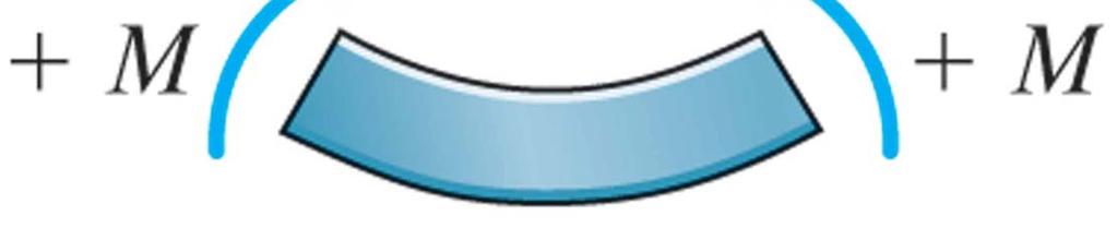
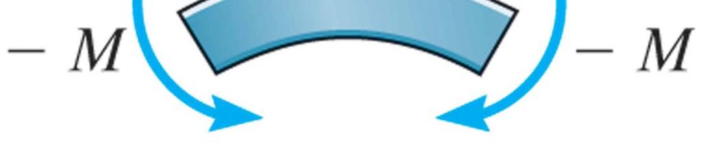
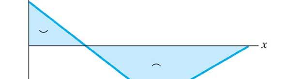
5 Beam Deflection To determine the deflection curve: Draw shear and moment diagram for the beam Directly under the moment diagram draw a line for the beam and label all supports At the supports displacement is zero Where the moment is negative, the dfl deflection curve is concave downward. Where the moment is positive the deflection curve is concave upward Where the two curve meet is the Inflection Point


6

7 Deflected Shape
8 Example 1 Draw the deflected shape for each of the beams shown
9 Example Draw the deflected shape for each of the frames shown
10 Double Integration Method


11 Elastic Beam Theory Consider a differential element of a beam subjected to pure bending. The radius of curvature ρ is measured from the center of curvature to the neutral axis Since the NA is unstretched, the dx=ρdθ

12 Elastic Beam Theory Applying Hooke s law and the Flexure formula, we obtain: 1 M = ρ EI
13 Elastic Beam Theory Theproduct EI is referred to as the flexuralrigidity rigidity. Since dx = ρdθ, then M d θ = dx (Slope) EI In mostcalculus books 1 ρ M EI d v dx d v / dx = 3 = [ 1+ ( dv / dx) ] = d v / dx [ + ( dv dx) ] 1 / M EI 3 ( exact solution lti )
14 The Double Integration Method Relate Moments to Deflections d v dx = M EI θ( x) ( ) dv = = M x dx dx EI ( x ) ( x ) M v( x) = dx EI ( x) Do Not Integration Constants Use Boundary Conditions to Evaluate Integration Constants
15 Assumptions and Limitations Deflections caused by shearing action negligibly small compared to bending Deflections are small compared to the cross sectional dimensions of the beam All portions of the beam are acting in the elastic range Beam is straight prior to the application of loads
16 y L x PL x Examples x P M = PL + d y EI = M d y dx EI = PL + Px dx dy x EI = PLx + P + c dx dy ( 0) = 0 EI 0 = PL 0 + P + c1 c1 = 0 dx 3 PLx x EIy = + P + c 6 3 PL ( 0) y = 0 EI( 0) = ( 0) + P + c c = 0 6 Integrating once x = 0 ( ) ( ) Integrating twice PLx EIy = + P y x = 0 ( ) ( ) x 6 3 EIy x = L y = y max PL L = 3 L + P = 6 PL 6 3 y max Px 3 PL = 3EI = PL max 3EI
17 WL y WL W x x L d y dx W x EI ( L x) W M = d y EI = M dx ( L x ) Integrating once ( L x) dy W EI = + c dx dy x = 0 = 0 EI( 0) = W ( L 0) c 1 c 1 WL = 6 3 EI dy dx = W 6 ( L x) 3 3 WL 6
18 Integrating twice 4 3 ( L x) WL W EIy = x + c x = 0 ( L 0) WL y = 0 EI( 0) = ( 0 ) y + c c = WL 4 4 W EIy = ( L x ) x WL WL 4 Max. x = L EIy max W L = 6 4 WL WL = 8 4 y max = 4 WL 8EI = max 4 WL 8 EI
19 Example y x WL WL WL x M = x Wx d y WL x EI = x W dx 3 dy WL x W x EI = + c dx L dy x = dx = 3 L L L WL ( ) = W EI 0 + c c1 = 3 Integrating g 1 x Since the beam is symmetric 0 = 1 EI dy dx L WL = 4 W 3 WL x x WL 4 3
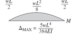
20 Integrating g WL x W x WL EIy = x + c x = 0y = 0 ( 0) W ( 0) WL EI ( 0) = ( 0 ) + c c = EIy = WL 1 x 3 W 4 x 4 WL 4 3 x Max. x = L / EIy = max 5WL max = 4 5WL 384EI
21 Example y x P x L/ L/ P P L P for 0 < x < M = x d y P L EI = x for 0 < x < dx dy P x EI = + c L dy x = dx = L L P = ( ) x EI 0 + c1 c1 = Integrating g 1 Since the beam is symmetric 0 EI dy dx = P 4 PL x 16 PL 16
22 Integrating g 3 P x PL EIy = x + c x = 0y = 0 ( 0) PL EI ( 0) = ( 0 ) + c c = EIy = P 1 x 3 PL 16 x Max. x = L / EIy = max PL 48 3 max = PL 3 48EI
23 Example
24 Example 5
25
26
27 Moment Area Theorems


28 Moment Area Theorems Theorem 1: The change in slope between any two points on the elastic curve equal to the area of the bending moment diagram between these two points, divided by the product EI. dv M dv = θ = dx EI dx dθ M M = dθ = dx dx EI EI θ B A B M = dx EI A


29 dt = xdθ M dθ = dx EI B M M tb A= x dx = x dx EI EI A B A
30 Moment Area Theorems Theorem : The vertical distance of point A on a elastic curve from the tangent drawn to the curve at B is equal to the moment of the area under the M/EI diagram between two points (A and B) about point A. B M ta B = x dx EI A B M ta B = x dx EI A
31 Example 1
32
33 Example
34
35 Example 3
36
37 Example 4
38
39 Example 5
40
41 Example 6
42
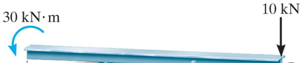
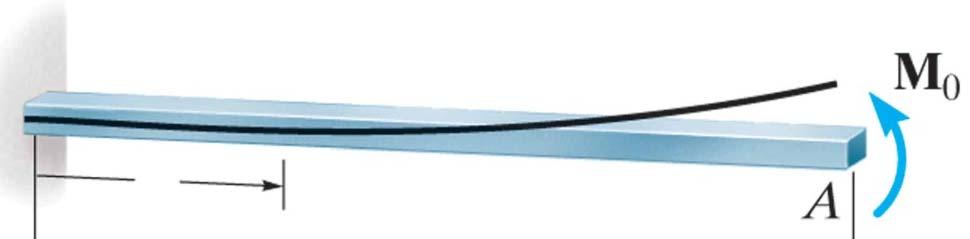
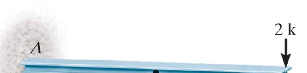
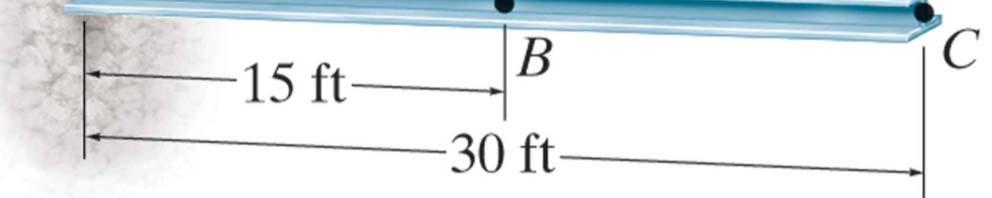
43 Example 7

44 M/EI 30/EI 0/EI t C / B = ( 1 ) + EI EI = kn m = rad EI

45 Another Solution
46 Conjugate-Beam Method


47 Conjugate-Beam Method dv d M w w dx = dx = dθ M d v M = = dx EI dx EI Integrating V = wdx M = wdx dx M M θ = dx v = dx dx EI EI


48 Conju ugate-beam Supports
49


50 Example 1 Find the Max. deflection Take E=00Gpa, I=60(10 6 )
 EI 5 B = V B ' B =")
51 θ 56. = EI 56.5 ' = (5) EI 5 B = V B ' B = M B = EI


52 Find the deflection at Point C Example C


53 C = M C ' = (1) (3) = EI EI EI

54 Find the deflection at Point D Example 3


55 3600 D = M D ' = EI EI EI
56 Find the Rotation at A Example 4 10 ft

57 θ A = 33.3 EI
58 Example 5
59 Copyright 009 Pearson Prentice Hall Inc.
60 Example 6
61
62


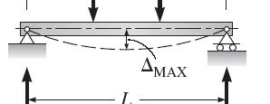
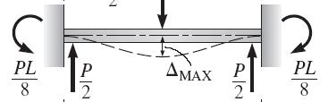
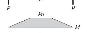
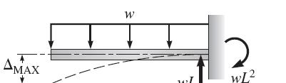
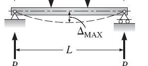
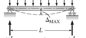
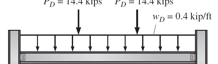
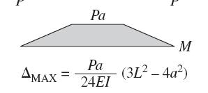
63 Moment Diagrams and Equations for Maximum Deflection
64

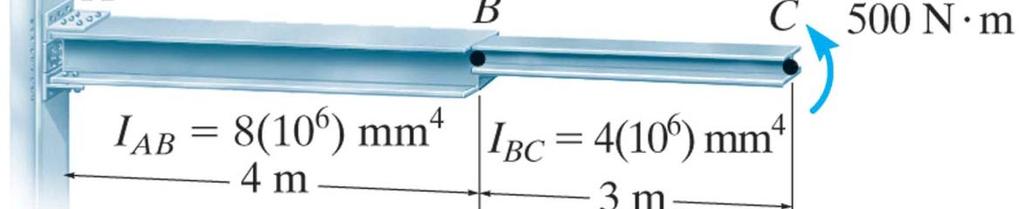
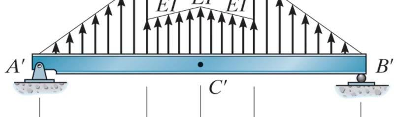
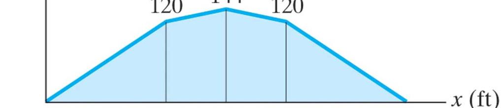
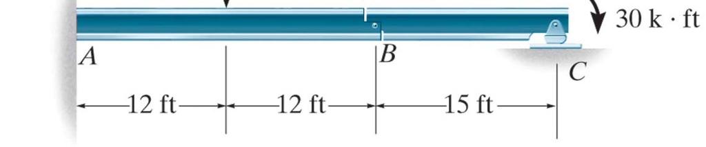
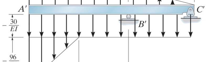
65 Example 4 Find the Maximum deflection for the following structure based on The previous diagrams
66
BEAM DEFLECTION THE ELASTIC CURVE
 BEAM DEFLECTION Samantha Ramirez THE ELASTIC CURVE The deflection diagram of the longitudinal axis that passes through the centroid of each cross-sectional area of a beam. Supports that apply a moment
CHAPTER OBJECTIVES Use various methods to determine the deflection and slope at specific pts on beams and shafts: 2. Discontinuity functions
 1. Deflections of Beams and Shafts CHAPTER OBJECTIVES Use various methods to determine the deflection and slope at specific pts on beams and shafts: 1. Integration method. Discontinuity functions 3. Method
Assumptions: beam is initially straight, is elastically deformed by the loads, such that the slope and deflection of the elastic curve are
 *12.4 SLOPE & DISPLACEMENT BY THE MOMENT-AREA METHOD Assumptions: beam is initially straight, is elastically deformed by the loads, such that the slope and deflection of the elastic curve are very small,
Chapter 8 Supplement: Deflection in Beams Double Integration Method
 Chapter 8 Supplement: Deflection in Beams Double Integration Method 8.5 Beam Deflection Double Integration Method In this supplement, we describe the methods for determining the equation of the deflection
8-5 Conjugate-Beam method. 8-5 Conjugate-Beam method. 8-5 Conjugate-Beam method. 8-5 Conjugate-Beam method
 The basis for the method comes from the similarity of eqn.1 &. to eqn 8. & 8. To show this similarity, we can write these eqn as shown dv dx w d θ M dx d M w dx d v M dx Here the shear V compares with
BEAM A horizontal or inclined structural member that is designed to resist forces acting to its axis is called a beam
 BEM horizontal or inclined structural member that is designed to resist forces acting to its axis is called a beam INTERNL FORCES IN BEM Whether or not a beam will break, depend on the internal resistances
Deflection of Flexural Members - Macaulay s Method 3rd Year Structural Engineering
 Deflection of Flexural Members - Macaulay s Method 3rd Year Structural Engineering 008/9 Dr. Colin Caprani 1 Contents 1. Introduction... 3 1.1 General... 3 1. Background... 4 1.3 Discontinuity Functions...
Deflection of Flexural Members - Macaulay s Method 3rd Year Structural Engineering
 Deflection of Flexural Members - Macaulay s Method 3rd Year Structural Engineering 009/10 Dr. Colin Caprani 1 Contents 1. Introduction... 4 1.1 General... 4 1. Background... 5 1.3 Discontinuity Functions...
Problem 1: Calculating deflection by integration uniform load. Problem 2: Calculating deflection by integration - triangular load pattern
 Problem 1: Calculating deflection by integration uniform load Problem 2: Calculating deflection by integration - triangular load pattern Problem 3: Deflections - by differential equations, concentrated
Chapter Objectives. Copyright 2011 Pearson Education South Asia Pte Ltd
 Chapter Objectives To generalize the procedure by formulating equations that can be plotted so that they describe the internal shear and moment throughout a member. To use the relations between distributed
Module 4 : Deflection of Structures Lecture 4 : Strain Energy Method
 Module 4 : Deflection of Structures Lecture 4 : Strain Energy Method Objectives In this course you will learn the following Deflection by strain energy method. Evaluation of strain energy in member under
FIXED BEAMS IN BENDING
 FIXED BEAMS IN BENDING INTRODUCTION Fixed or built-in beams are commonly used in building construction because they possess high rigidity in comparison to simply supported beams. When a simply supported
CHAPTER 7 DEFLECTIONS OF BEAMS
 CHPTER 7 DEFLECTIONS OF EMS OJECTIVES Determine the deflection and slope at specific points on beams and shafts, using various analytical methods including: o o o The integration method The use of discontinuity
Chapter 7: Internal Forces
 Chapter 7: Internal Forces Chapter Objectives To show how to use the method of sections for determining the internal loadings in a member. To generalize this procedure by formulating equations that can
 UNIT III DEFLECTION OF BEAMS 1. What are the methods for finding out the slope and deflection at a section? The important methods used for finding out the slope and deflection at a section in a loaded
dv dx Slope of the shear diagram = - Value of applied loading dm dx Slope of the moment curve = Shear Force
 Beams SFD and BMD Shear and Moment Relationships w dv dx Slope of the shear diagram = - Value of applied loading V dm dx Slope of the moment curve = Shear Force Both equations not applicable at the point
Moment Area Method. 1) Read
 Read") Moment Area Method Lesson Objectives: 1) Identify the formulation and sign conventions associated with the Moment Area method. 2) Derive the Moment Area method theorems using mechanics and mathematics.
Moment Area Method Lesson Objectives: 1) Identify the formulation and sign conventions associated with the Moment Area method. 2) Derive the Moment Area method theorems using mechanics and mathematics.
Module 2. Analysis of Statically Indeterminate Structures by the Matrix Force Method
 Module 2 Analysis of Statically Indeterminate Structures by the Matrix Force Method Lesson 8 The Force Method of Analysis: Beams Instructional Objectives After reading this chapter the student will be
Chapter 2: Deflections of Structures
 Chapter 2: Deflections of Structures Fig. 4.1. (Fig. 2.1.) ASTU, Dept. of C Eng., Prepared by: Melkamu E. Page 1 (2.1) (4.1) (2.2) Fig.4.2 Fig.2.2 ASTU, Dept. of C Eng., Prepared by: Melkamu E. Page 2
3. BEAMS: STRAIN, STRESS, DEFLECTIONS
 3. BEAMS: STRAIN, STRESS, DEFLECTIONS The beam, or flexural member, is frequently encountered in structures and machines, and its elementary stress analysis constitutes one of the more interesting facets
7.4 The Elementary Beam Theory
 7.4 The Elementary Beam Theory In this section, problems involving long and slender beams are addressed. s with pressure vessels, the geometry of the beam, and the specific type of loading which will be
CHAPTER THREE SYMMETRIC BENDING OF CIRCLE PLATES
 CHAPTER THREE SYMMETRIC BENDING OF CIRCLE PLATES * Governing equations in beam and plate bending ** Solution by superposition 1.1 From Beam Bending to Plate Bending 1.2 Governing Equations For Symmetric
[8] Bending and Shear Loading of Beams
![[8] Bending and Shear Loading of Beams](/thumbs/92/110949676.jpg "[8] Bending and Shear Loading of Beams") [8] Bending and Shear Loading of Beams Page 1 of 28 [8] Bending and Shear Loading of Beams [8.1] Bending of Beams (will not be covered in class) [8.2] Bending Strain and Stress [8.3] Shear in Straight
[8] Bending and Shear Loading of Beams Page 1 of 28 [8] Bending and Shear Loading of Beams [8.1] Bending of Beams (will not be covered in class) [8.2] Bending Strain and Stress [8.3] Shear in Straight
Module 3. Analysis of Statically Indeterminate Structures by the Displacement Method
 odule 3 Analysis of Statically Indeterminate Structures by the Displacement ethod Lesson 16 The Slope-Deflection ethod: rames Without Sidesway Instructional Objectives After reading this chapter the student
Physics 8 Monday, November 20, 2017
 Physics 8 Monday, November 20, 2017 Pick up HW11 handout, due Dec 1 (Friday next week). This week, you re skimming/reading O/K ch8, which goes into more detail on beams. Since many people will be traveling
FIXED BEAMS CONTINUOUS BEAMS
 FIXED BEAMS CONTINUOUS BEAMS INTRODUCTION A beam carried over more than two supports is known as a continuous beam. Railway bridges are common examples of continuous beams. But the beams in railway bridges
x+ y = 50 Dividing both sides by 2 : ( ) dx By (7.2), x = 25m gives maximum area. Substituting this value into (*):
 dx By (7.2), x = 25m gives maximum area. Substituting this value into (*):") Solutions 7(b 1 Complete solutions to Exercise 7(b 1. Since the perimeter 100 we have x+ y 100 [ ] ( x+ y 50 ividing both sides by : y 50 x * The area A xy, substituting y 50 x gives: A x( 50 x A 50x x
Solutions 7(b 1 Complete solutions to Exercise 7(b 1. Since the perimeter 100 we have x+ y 100 [ ] ( x+ y 50 ividing both sides by : y 50 x * The area A xy, substituting y 50 x gives: A x( 50 x A 50x x
Lecture 15 Strain and stress in beams
 Spring, 2019 ME 323 Mechanics of Materials Lecture 15 Strain and stress in beams Reading assignment: 6.1 6.2 News: Instructor: Prof. Marcial Gonzalez Last modified: 1/6/19 9:42:38 PM Beam theory (@ ME
Deflections. Deflections. Deflections. Deflections. Deflections. Deflections. dx dm V. dx EI. dx EI dx M. dv w
 CIVL 311 - Conjugate eam 1/5 Conjugate beam method The development of the conjugate beam method has been atributed to several strucutral engineers. any credit Heinrich üller-reslau (1851-195) with the
Beam Design and Deflections
 Beam Design and Deflections tation: a = name for width dimension A = name for area Areq d-adj = area required at allowable stress when shear is adjusted to include self weight Aweb = area of the web of
PURE BENDING. If a simply supported beam carries two point loads of 10 kn as shown in the following figure, pure bending occurs at segment BC.
 BENDING STRESS The effect of a bending moment applied to a cross-section of a beam is to induce a state of stress across that section. These stresses are known as bending stresses and they act normally
14. *14.8 CASTIGLIANO S THEOREM
 *14.8 CASTIGLIANO S THEOREM Consider a body of arbitrary shape subjected to a series of n forces P 1, P 2, P n. Since external work done by forces is equal to internal strain energy stored in body, by
Chapter 5 Elastic Strain, Deflection, and Stability 1. Elastic Stress-Strain Relationship
 Chapter 5 Elastic Strain, Deflection, and Stability Elastic Stress-Strain Relationship A stress in the x-direction causes a strain in the x-direction by σ x also causes a strain in the y-direction & z-direction
CHAPTER -6- BENDING Part -1-
 Ishik University / Sulaimani Civil Engineering Department Mechanics of Materials CE 211 CHAPTER -6- BENDING Part -1-1 CHAPTER -6- Bending Outlines of this chapter: 6.1. Chapter Objectives 6.2. Shear and
Symmetric Bending of Beams
 Symmetric Bending of Beams beam is any long structural member on which loads act perpendicular to the longitudinal axis. Learning objectives Understand the theory, its limitations and its applications
External Work. When a force F undergoes a displacement dx in the same direction i as the force, the work done is
 Structure Analysis I Chapter 9 Deflection Energy Method External Work Energy Method When a force F undergoes a displacement dx in the same direction i as the force, the work done is du e = F dx If the
Review Lecture. AE1108-II: Aerospace Mechanics of Materials. Dr. Calvin Rans Dr. Sofia Teixeira De Freitas
 Review Lecture AE1108-II: Aerospace Mechanics of Materials Dr. Calvin Rans Dr. Sofia Teixeira De Freitas Aerospace Structures & Materials Faculty of Aerospace Engineering Analysis of an Engineering System
6. Bending CHAPTER OBJECTIVES
 CHAPTER OBJECTIVES Determine stress in members caused by bending Discuss how to establish shear and moment diagrams for a beam or shaft Determine largest shear and moment in a member, and specify where
Beams. Beams are structural members that offer resistance to bending due to applied load
 Beams Beams are structural members that offer resistance to bending due to applied load 1 Beams Long prismatic members Non-prismatic sections also possible Each cross-section dimension Length of member
Chapter 8 Deflection. Structural Mechanics 2 Dept of Architecture
 Chapter 8 Deflection Structural echanics Dept of rchitecture Outline Deflection diagras and the elastic curve Elastic-bea theory The double integration ethod oent-area theores Conjugate-bea ethod 8- Deflection
8.3 Shear and Bending-Moment Diagrams Constructed by Areas
 8.3 Shear and ending-moment Diagrams Constructed by reas 8.3 Shear and ending-moment Diagrams Constructed by reas Procedures and Strategies, page 1 of 3 Procedures and Strategies for Solving Problems Involving
Application of Finite Element Method to Create Animated Simulation of Beam Analysis for the Course of Mechanics of Materials
 International Conference on Engineering Education and Research "Progress Through Partnership" 4 VSB-TUO, Ostrava, ISSN 156-35 Application of Finite Element Method to Create Animated Simulation of Beam
General elastic beam with an elastic foundation
 General elastic beam with an elastic foundation Figure 1 shows a beam-column on an elastic foundation. The beam is connected to a continuous series of foundation springs. The other end of the foundation
Module 2. Analysis of Statically Indeterminate Structures by the Matrix Force Method
 Module 2 Analysis of Statically Indeterminate Structures by the Matrix Force Method Lesson 11 The Force Method of Analysis: Frames Instructional Objectives After reading this chapter the student will be
Mechanics in Energy Resources Engineering - Chapter 5 Stresses in Beams (Basic topics)
") Week 7, 14 March Mechanics in Energy Resources Engineering - Chapter 5 Stresses in Beams (Basic topics) Ki-Bok Min, PhD Assistant Professor Energy Resources Engineering i Seoul National University Shear
Week 7, 14 March Mechanics in Energy Resources Engineering - Chapter 5 Stresses in Beams (Basic topics) Ki-Bok Min, PhD Assistant Professor Energy Resources Engineering i Seoul National University Shear
Method of Virtual Work Frame Deflection Example Steven Vukazich San Jose State University
 Method of Virtual Work Frame Deflection xample Steven Vukazich San Jose State University Frame Deflection xample 9 k k D 4 ft θ " # The statically determinate frame from our previous internal force diagram
Module 3. Analysis of Statically Indeterminate Structures by the Displacement Method
 odule 3 Analysis of Statically Indeterminate Structures by the Displacement ethod Lesson 14 The Slope-Deflection ethod: An Introduction Introduction As pointed out earlier, there are two distinct methods
Mechanical Design in Optical Engineering
 OPTI Buckling Buckling and Stability: As we learned in the previous lectures, structures may fail in a variety of ways, depending on the materials, load and support conditions. We had two primary concerns:
Chapter 7: Bending and Shear in Simple Beams
 Chapter 7: Bending and Shear in Simple Beams Introduction A beam is a long, slender structural member that resists loads that are generally applied transverse (perpendicular) to its longitudinal axis.
Stress Analysis Lecture 4 ME 276 Spring Dr./ Ahmed Mohamed Nagib Elmekawy
 Stress Analysis Lecture 4 ME 76 Spring 017-018 Dr./ Ahmed Mohamed Nagib Elmekawy Shear and Moment Diagrams Beam Sign Convention The positive directions are as follows: The internal shear force causes a
ME325 EXAM I (Sample)
") ME35 EXAM I (Sample) NAME: NOTE: COSED BOOK, COSED NOTES. ONY A SINGE 8.5x" ORMUA SHEET IS AOWED. ADDITIONA INORMATION IS AVAIABE ON THE AST PAGE O THIS EXAM. DO YOUR WORK ON THE EXAM ONY (NO SCRATCH PAPER
ME35 EXAM I (Sample) NAME: NOTE: COSED BOOK, COSED NOTES. ONY A SINGE 8.5x" ORMUA SHEET IS AOWED. ADDITIONA INORMATION IS AVAIABE ON THE AST PAGE O THIS EXAM. DO YOUR WORK ON THE EXAM ONY (NO SCRATCH PAPER
Shear Force V: Positive shear tends to rotate the segment clockwise.
 INTERNL FORCES IN EM efore a structural element can be designed, it is necessary to determine the internal forces that act within the element. The internal forces for a beam section will consist of a shear
ENG2000 Chapter 7 Beams. ENG2000: R.I. Hornsey Beam: 1
 ENG2000 Chapter 7 Beams ENG2000: R.I. Hornsey Beam: 1 Overview In this chapter, we consider the stresses and moments present in loaded beams shear stress and bending moment diagrams We will also look at
LECTURE 14 Strength of a Bar in Transverse Bending. 1 Introduction. As we have seen, only normal stresses occur at cross sections of a rod in pure
 V. DEMENKO MECHNCS OF MTERLS 015 1 LECTURE 14 Strength of a Bar in Transverse Bending 1 ntroduction s we have seen, onl normal stresses occur at cross sections of a rod in pure bending. The corresponding
Portal Frame Calculations Lateral Loads
 Portal Frame Calculations Lateral Loads Consider the following multi-story frame: The portal method makes several assumptions about the internal forces of the columns and beams in a rigid frame: 1) Inflection
Investigation of Slopes and Deflections of a Stepped Beam Using a Global Formula for
 Investigation of Slopes and Deflections of a Stepped Beam Using a Global Formula for An Undergraduate Honors College Thesis in the Departmanet of Mechnical Engineering College of Engineering University
Chapter 4.1: Shear and Moment Diagram
 Chapter 4.1: Shear and Moment Diagram Chapter 5: Stresses in Beams Chapter 6: Classical Methods Beam Types Generally, beams are classified according to how the beam is supported and according to crosssection
D : SOLID MECHANICS. Q. 1 Q. 9 carry one mark each. Q.1 Find the force (in kn) in the member BH of the truss shown.
 in the member BH of the truss shown.") D : SOLID MECHANICS Q. 1 Q. 9 carry one mark each. Q.1 Find the force (in kn) in the member BH of the truss shown. Q.2 Consider the forces of magnitude F acting on the sides of the regular hexagon having
D : SOLID MECHANICS Q. 1 Q. 9 carry one mark each. Q.1 Find the force (in kn) in the member BH of the truss shown. Q.2 Consider the forces of magnitude F acting on the sides of the regular hexagon having
Stresses in Curved Beam
 Stresses in Curved Beam Consider a curved beam subjected to bending moment M b as shown in the figure. The distribution of stress in curved flexural member is determined by using the following assumptions:
Discontinuous Distributions in Mechanics of Materials
 Discontinuous Distributions in Mechanics of Materials J.E. Akin, Rice University 1. Introduction The study of the mechanics of materials continues to change slowly. The student needs to learn about software
DEFLECTION CALCULATIONS (from Nilson and Nawy)
") DEFLECTION CALCULATIONS (from Nilson and Nawy) The deflection of a uniformly loaded flat plate, flat slab, or two-way slab supported by beams on column lines can be calculated by an equivalent method that
DEFLECTION CALCULATIONS (from Nilson and Nawy) The deflection of a uniformly loaded flat plate, flat slab, or two-way slab supported by beams on column lines can be calculated by an equivalent method that
bending moment in the beam can be obtained by integration
 q 0 L 4 B = - v(l) = CCC ( ) 30 EI Example 9-5 an overhanging beam ABC with a concentrated load P applied at the end determine the equation of deflection curve and the deflection C at the end flexural
Procedure for drawing shear force and bending moment diagram:
 Procedure for drawing shear force and bending moment diagram: Preamble: The advantage of plotting a variation of shear force F and bending moment M in a beam as a function of x' measured from one end of
Physics 8 Monday, November 23, 2015
 Physics 8 Monday, November 23, 2015 Handing out HW11, due Friday, December 4. One or two more beam-related examples, then we ll move on to oscillations ( periodic motion ). This week s reading is Mazur
SERVICEABILITY OF BEAMS AND ONE-WAY SLABS
 CHAPTER REINFORCED CONCRETE Reinforced Concrete Design A Fundamental Approach - Fifth Edition Fifth Edition SERVICEABILITY OF BEAMS AND ONE-WAY SLABS A. J. Clark School of Engineering Department of Civil
MEMS Report for Lab #3. Use of Strain Gages to Determine the Strain in Cantilever Beams
 MEMS 1041 Report for Lab #3 Use of Strain Gages to Determine the Strain in Cantilever Beams Date: February 9, 2016 Lab Instructor: Robert Carey Submitted by: Derek Nichols Objective: The objective of this
Purpose of this Guide: To thoroughly prepare students for the exact types of problems that will be on Exam 3.
 ES230 STRENGTH OF MTERILS Exam 3 Study Guide Exam 3: Wednesday, March 8 th in-class Updated 3/3/17 Purpose of this Guide: To thoroughly prepare students for the exact types of problems that will be on
Chapter 11. Displacement Method of Analysis Slope Deflection Method
 Chapter 11 Displacement ethod of Analysis Slope Deflection ethod Displacement ethod of Analysis Two main methods of analyzing indeterminate structure Force method The method of consistent deformations
Unit III Theory of columns. Dr.P.Venkateswara Rao, Associate Professor, Dept. of Civil Engg., SVCE, Sriperumbudir
 Unit III Theory of columns 1 Unit III Theory of Columns References: Punmia B.C.,"Theory of Structures" (SMTS) Vol II, Laxmi Publishing Pvt Ltd, New Delhi 2004. Rattan.S.S., "Strength of Materials", Tata
ME C85/CE C30 Fall, Introduction to Solid Mechanics ME C85/CE C30. Final Exam. Fall, 2013
 Introduction to Solid Mechanics ME C85/CE C30 Fall, 2013 1. Leave an empty seat between you and the person (people) next to you. Unfortunately, there have been reports of cheating on the midterms, so we
UNIT I ENERGY PRINCIPLES
 UNIT I ENERGY PRINCIPLES Strain energy and strain energy density- strain energy in traction, shear in flexure and torsion- Castigliano s theorem Principle of virtual work application of energy theorems
Problem d d d B C E D. 0.8d. Additional lecturebook examples 29 ME 323
 Problem 9.1 Two beam segments, AC and CD, are connected together at C by a frictionless pin. Segment CD is cantilevered from a rigid support at D, and segment AC has a roller support at A. a) Determine
Chapter 4 Deflection and Stiffness
 Chapter 4 Deflection and Stiffness Asst. Prof. Dr. Supakit Rooppakhun Chapter Outline Deflection and Stiffness 4-1 Spring Rates 4-2 Tension, Compression, and Torsion 4-3 Deflection Due to Bending 4-4 Beam
SIMPLY SUPPORTED STRUCTURAL BEAM STRESS AND DEFLECTION ANAL
 1 of 6 22/03/2016 09:17 HOMEPAGE CALCULATORS EXAMPLES GUIDELINES SIMPLY SUPPORTED STRUCTURAL BEAM STRESS AND DEFLECTION ANAL Following calculator has been developed to find forces, moments, stresses, deflections
INFLUENCE LINE. Structural Analysis. Reference: Third Edition (2005) By Aslam Kassimali
 By Aslam Kassimali") INFLUENCE LINE Reference: Structural Analsis Third Edition (2005) B Aslam Kassimali DEFINITION An influence line is a graph of a response function of a structure as a function of the position of a downward
INFLUENCE LINE Reference: Structural Analsis Third Edition (2005) B Aslam Kassimali DEFINITION An influence line is a graph of a response function of a structure as a function of the position of a downward
Types of Structures & Loads
 Structure Analysis I Chapter 4 1 Types of Structures & Loads 1Chapter Chapter 4 Internal lloading Developed in Structural Members Internal loading at a specified Point In General The loading for coplanar
Mechanics of Materials MENG 270 Fall 2003 Exam 3 Time allowed: 90min. Q.1(a) Q.1 (b) Q.2 Q.3 Q.4 Total
 Q.1 (b) Q.2 Q.3 Q.4 Total") Mechanics of Materials MENG 70 Fall 00 Eam Time allowed: 90min Name. Computer No. Q.(a) Q. (b) Q. Q. Q.4 Total Problem No. (a) [5Points] An air vessel is 500 mm average diameter and 0 mm thickness, the
Mechanics of Materials MENG 70 Fall 00 Eam Time allowed: 90min Name. Computer No. Q.(a) Q. (b) Q. Q. Q.4 Total Problem No. (a) [5Points] An air vessel is 500 mm average diameter and 0 mm thickness, the
QUESTION BANK DEPARTMENT: CIVIL SEMESTER: III SUBJECT CODE: CE2201 SUBJECT NAME: MECHANICS OF SOLIDS UNIT 1- STRESS AND STRAIN PART A
 DEPARTMENT: CIVIL SUBJECT CODE: CE2201 QUESTION BANK SEMESTER: III SUBJECT NAME: MECHANICS OF SOLIDS UNIT 1- STRESS AND STRAIN PART A (2 Marks) 1. Define longitudinal strain and lateral strain. 2. State
QUESTION BANK SEMESTER: III SUBJECT NAME: MECHANICS OF SOLIDS
 QUESTION BANK SEMESTER: III SUBJECT NAME: MECHANICS OF SOLIDS UNIT 1- STRESS AND STRAIN PART A (2 Marks) 1. Define longitudinal strain and lateral strain. 2. State Hooke s law. 3. Define modular ratio,
Calculus and Structures
 Calculus and Structures CHAPTER 8 SHEAR FORCE AND BENDING MOMENTS FOR BEAMS WITH CONTINUOUS FORCES Calculus and Structures 11 Copyright Chapter 8 CONTINUOUS FORCE 8.1 INTRODUCTION The last section was
Initial Stress Calculations
 Initial Stress Calculations The following are the initial hand stress calculations conducted during the early stages of the design process. Therefore, some of the material properties as well as dimensions
Consider an elastic spring as shown in the Fig.2.4. When the spring is slowly
 .3 Strain Energy Consider an elastic spring as shown in the Fig..4. When the spring is slowly pulled, it deflects by a small amount u 1. When the load is removed from the spring, it goes back to the original
M5 Simple Beam Theory (continued)
") M5 Simple Beam Theory (continued) Reading: Crandall, Dahl and Lardner 7.-7.6 In the previous lecture we had reached the point of obtaining 5 equations, 5 unknowns by application of equations of elasticity
M5 Simple Beam Theory (continued) Reading: Crandall, Dahl and Lardner 7.-7.6 In the previous lecture we had reached the point of obtaining 5 equations, 5 unknowns by application of equations of elasticity
Rigid Pavement Mechanics. Curling Stresses
 Rigid Pavement Mechanics Curling Stresses Major Distress Conditions Cracking Bottom-up transverse cracks Top-down transverse cracks Longitudinal cracks Corner breaks Punchouts (CRCP) 2 Major Distress Conditions
CITY AND GUILDS 9210 UNIT 135 MECHANICS OF SOLIDS Level 6 TUTORIAL 5A - MOMENT DISTRIBUTION METHOD
 Outcome 1 The learner can: CITY AND GUIDS 910 UNIT 15 ECHANICS OF SOIDS evel 6 TUTORIA 5A - OENT DISTRIBUTION ETHOD Calculate stresses, strain and deflections in a range of components under various load
SECTION A. 8 kn/m. C 3 m 3m
 SECTION Question 1 150 m 40 kn 5 kn 8 kn/m C 3 m 3m D 50 ll dimensions in mm 15 15 Figure Q1(a) Figure Q1(b) The horizontal beam CD shown in Figure Q1(a) has a uniform cross-section as shown in Figure
twenty one concrete construction: shear & deflection ARCHITECTURAL STRUCTURES: FORM, BEHAVIOR, AND DESIGN DR. ANNE NICHOLS SUMMER 2014 lecture
 ARCHITECTURAL STRUCTURES: FORM, BEHAVIOR, AND DESIGN DR. ANNE NICHOLS SUMMER 2014 lecture twenty one concrete construction: Copyright Kirk Martini shear & deflection Concrete Shear 1 Shear in Concrete
Beams on elastic foundation
 Beams on elastic foundation I Basic concepts The beam lies on elastic foundation when under the applied eternal loads, the reaction forces of the foundation are proportional at every point to the deflection
Shear force and bending moment of beams 2.1 Beams 2.2 Classification of beams 1. Cantilever Beam Built-in encastre' Cantilever
 CHAPTER TWO Shear force and bending moment of beams 2.1 Beams A beam is a structural member resting on supports to carry vertical loads. Beams are generally placed horizontally; the amount and extent of
P.E. Civil Exam Review:
 P.E. Civil Exam Review: Structural Analysis J.P. Mohsen Email: jpm@louisville.edu Structures Determinate Indeterminate STATICALLY DETERMINATE STATICALLY INDETERMINATE Stability and Determinacy of Trusses
A study of the critical condition of a battened column and a frame by classical methods
 University of South Florida Scholar Commons Graduate Theses and Dissertations Graduate School 003 A study of the critical condition of a battened column and a frame by classical methods Jamal A.H Bekdache
STRENGTH OF MATERIALS-I. Unit-1. Simple stresses and strains
 STRENGTH OF MATERIALS-I Unit-1 Simple stresses and strains 1. What is the Principle of surveying 2. Define Magnetic, True & Arbitrary Meridians. 3. Mention different types of chains 4. Differentiate between
FINAL EXAMINATION. (CE130-2 Mechanics of Materials)
") UNIVERSITY OF CLIFORNI, ERKELEY FLL SEMESTER 001 FINL EXMINTION (CE130- Mechanics of Materials) Problem 1: (15 points) pinned -bar structure is shown in Figure 1. There is an external force, W = 5000N,
UNIVERSITY OF CLIFORNI, ERKELEY FLL SEMESTER 001 FINL EXMINTION (CE130- Mechanics of Materials) Problem 1: (15 points) pinned -bar structure is shown in Figure 1. There is an external force, W = 5000N,
REVIEW FOR EXAM II. Dr. Ibrahim A. Assakkaf SPRING 2002
 REVIEW FOR EXM II. J. Clark School of Engineering Department of Civil and Environmental Engineering b Dr. Ibrahim. ssakkaf SPRING 00 ENES 0 Mechanics of Materials Department of Civil and Environmental
Structural Analysis III The Moment Area Method Mohr s Theorems
 Structural Analysis III The Moment Area Method Mohr s Theorems 009/10 Dr. Colin Caprani 1 Contents 1. Introduction... 4 1.1 Purpose... 4. Theory... 6.1 asis... 6. Mohr s First Theorem (Mohr I)... 8.3 Mohr
two structural analysis (statics & mechanics) APPLIED ACHITECTURAL STRUCTURES: DR. ANNE NICHOLS SPRING 2017 lecture STRUCTURAL ANALYSIS AND SYSTEMS
 APPLIED ACHITECTURAL STRUCTURES: DR. ANNE NICHOLS SPRING 2017 lecture STRUCTURAL ANALYSIS AND SYSTEMS") APPLIED ACHITECTURAL STRUCTURES: STRUCTURAL ANALYSIS AND SYSTEMS DR. ANNE NICHOLS SPRING 2017 lecture two structural analysis (statics & mechanics) Analysis 1 Structural Requirements strength serviceability
APPLIED ACHITECTURAL STRUCTURES: STRUCTURAL ANALYSIS AND SYSTEMS DR. ANNE NICHOLS SPRING 2017 lecture two structural analysis (statics & mechanics) Analysis 1 Structural Requirements strength serviceability
Chapter 12 Elastic Stability of Columns
 Chapter 12 Elastic Stability of Columns Axial compressive loads can cause a sudden lateral deflection (Buckling) For columns made of elastic-perfectly plastic materials, P cr Depends primarily on E and
Beams are bars of material that support. Beams are common structural members. Beams can support both concentrated and distributed loads
 Outline: Review External Effects on Beams Beams Internal Effects Sign Convention Shear Force and Bending Moment Diagrams (text method) Relationships between Loading, Shear Force and Bending Moments (faster
THE AREA-MOMENT / MOMENT-AREA METHODS:
 THE AREA-MOMENT / MOMENT-AREA METHODS: The area moment method is a semi graphical method of dealing with problems of deflection of beams subjected to bending. The method is based on a geometrical interpretation
MAHALAKSHMI ENGINEERING COLLEGE
 AHAAKSHI ENGINEERING COEGE TIRUCHIRAPAI - 611. QUESTION WITH ANSWERS DEPARTENT : CIVI SEESTER: V SU.CODE/ NAE: CE 5 / Strength of aterials UNIT INDETERINATE EAS 1. Define statically indeterminate beams.