Chapter Objectives. Copyright 2011 Pearson Education South Asia Pte Ltd
|
|
|
- Camron Berry
- 5 years ago
- Views:
Transcription

1 Chapter Objectives To generalize the procedure by formulating equations that can be plotted so that they describe the internal shear and moment throughout a member. To use the relations between distributed load, shear, and moment to draw shear and moment diagrams. To determine the stress in elastic symmetric members subject to bending.
2 In-class Activities 1. Reading Quiz 2. Applications 3. Shear and moment diagrams 4. Graphical method for construction of shear and bending moment diagrams 5. Flexural formula 6. Unsymmetric bending 7. Stress Concentrations 8. Concept Quiz
3 READING QUIZ 1) Provided that the bending formation of a straight member is small and within elastic range, which of the following statements is incorrect? a) Plane section remains plane b) Cross section remains perpendicular c) The length of the longitudinal axis remains unchanged d) In-plane distortion of cross section to the longitudinal axis is not negligible
4 READING QUIZ (cont) 2) Which of the following statements is incorrect for bending of a straight member? a) Bending stress is proportional to b) Bending stress is inversely proportional c) Bending stress is inversely proportional to the moment of inertia of the section d) Bending stress is not a function to the second moment of area of the section of the location
5 APPLICATIONS
6
7
8 APPLICATIONS (cont)


9 SHEAR AND MOMENT DIAGRAMS Shear is obtained by summing forces perpendicular to the beam s axis up to the end of the segment. Please refer to the website for the animation: Shear and Moment Diagrams Moment is obtained by summing moments about the end of the segment. Note the sign conventions are opposite when the summing processes are carried out with opposite direction. (from left to right vs from right to left)

10 EXAMPLE 1 Draw the shear and moment diagrams for the beam shown in Fig. 6 4a.
 Solution The support reactions are shown in")

11 EXAMPLE 1 (cont.) Solution The support reactions are shown in Fig. 6 4c. Applying the two equations of equilibrium yields F y 0; wl 2 V wx V w L x M 0; wl x 2 wx x M 2 0 M w 2 2 Lx x 2
12 EXAMPLE 1 (cont.) Solution The point of zero shear can be found from Eq. 1: V w L x 2 L x 2 0 From the moment diagram, this value of x represents the point on the beam where the maximum moment occurs. M max w 2 L L 2 L 2 2 wl 8 2

13 GRAPHICAL METHOD FOR CONSTRUCTING SHEAR AND MOMENT DIAGRAMS Regions of distributed load: Change in shear = area under distributed loading V w x dx Change in moment = area under shear diagram M V xdx

14 GRAPHICAL METHOD FOR CONSTRUCTING SHEAR AND MOMENT DIAGRAMS (cont) Regions of concentrated force and moment: V F V V 0 V F M M M M Vx M 0 0 M 0

15 EXAMPLE 2 Draw the shear and moment diagrams for the beam shown in Fig. 6 12a.
16 EXAMPLE 2 (cont.) Solution The reactions are shown on the free-body diagram in Fig. 6 12b. The shear at each end is plotted first, Fig. 6 12c. Since there is no distributed load on the beam, the shear diagram has zero slope and is therefore a horizontal line.
17 EXAMPLE 2 (cont.) Solution The moment is zero at each end, Fig. 6 12d. The moment diagram has a constant negative slope of -M 0 /2L since this is the shear in the beam at each point. Note that the couple moment causes a jump in the moment diagram at the beam s center, but it does not affect the shear diagram at this point.


18 EXAMPLE 3 Draw the shear and moment diagrams for each of the beams shown in Figs. 6 13a and 6 14a.
")
19 EXAMPLE 3 (cont) Solution


20 BENDING DEFORMATION OF A STRAIGHT MEMBER Assumptions: 1. Plane section remains plane 2. Length of longitudinal axis remains unchanged 3. Plane section remains perpendicular to the longitudinal axis 4. In-plane distortion of section is negligible


21 FLEXURAL FORMULA Assumptions: Material behaves in a linear-elastic manner so that Hooke s Law Applies; i.e. σ=e.є My I M M R Z M ydf max M c Mc max I My I A y Z 2 ; A y da da A y y c max da

22 EXAMPLE 4 The simply supported beam in Fig. 6 26a has the crosssectional area shown in Fig. 6 26b. Determine the absolute maximum bending stress in the beam and draw the stress distribution over the cross section at this location.

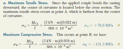
23 EXAMPLE 4 (cont) Solution The maximum internal moment in the beam, 22.5 knm, occurs at the center. By reasons of symmetry, the neutral axis passes through the centroid C at the mid-height of the beam, Fig. 6 26b. I 2 2 I Ad m B My I B ; b MPa (Ans)

24 EXAMPLE 4 (cont) Solution A three-dimensional view of the stress distribution is shown in Fig. 6 26d. At point B, B My I B ; B MPa
25 Example
26 Solution
27 Solution
6. Bending CHAPTER OBJECTIVES
 CHAPTER OBJECTIVES Determine stress in members caused by bending Discuss how to establish shear and moment diagrams for a beam or shaft Determine largest shear and moment in a member, and specify where
PURE BENDING. If a simply supported beam carries two point loads of 10 kn as shown in the following figure, pure bending occurs at segment BC.
 BENDING STRESS The effect of a bending moment applied to a cross-section of a beam is to induce a state of stress across that section. These stresses are known as bending stresses and they act normally
[8] Bending and Shear Loading of Beams
![[8] Bending and Shear Loading of Beams](/thumbs/92/110949676.jpg "[8] Bending and Shear Loading of Beams") [8] Bending and Shear Loading of Beams Page 1 of 28 [8] Bending and Shear Loading of Beams [8.1] Bending of Beams (will not be covered in class) [8.2] Bending Strain and Stress [8.3] Shear in Straight
[8] Bending and Shear Loading of Beams Page 1 of 28 [8] Bending and Shear Loading of Beams [8.1] Bending of Beams (will not be covered in class) [8.2] Bending Strain and Stress [8.3] Shear in Straight
CHAPTER -6- BENDING Part -1-
 Ishik University / Sulaimani Civil Engineering Department Mechanics of Materials CE 211 CHAPTER -6- BENDING Part -1-1 CHAPTER -6- Bending Outlines of this chapter: 6.1. Chapter Objectives 6.2. Shear and
MECE 3321: Mechanics of Solids Chapter 6
 MECE 3321: Mechanics of Solids Chapter 6 Samantha Ramirez Beams Beams are long straight members that carry loads perpendicular to their longitudinal axis Beams are classified by the way they are supported
Chapter Objectives. Copyright 2011 Pearson Education South Asia Pte Ltd
 Chapter Objectives To determine the torsional deformation of a perfectly elastic circular shaft. To determine the support reactions when these reactions cannot be determined solely from the moment equilibrium
Stress Analysis Lecture 4 ME 276 Spring Dr./ Ahmed Mohamed Nagib Elmekawy
 Stress Analysis Lecture 4 ME 76 Spring 017-018 Dr./ Ahmed Mohamed Nagib Elmekawy Shear and Moment Diagrams Beam Sign Convention The positive directions are as follows: The internal shear force causes a
Samantha Ramirez, MSE
 Samantha Ramirez, MSE Centroids The centroid of an area refers to the point that defines the geometric center for the area. In cases where the area has an axis of symmetry, the centroid will lie along
7 TRANSVERSE SHEAR transverse shear stress longitudinal shear stresses
 7 TRANSVERSE SHEAR Before we develop a relationship that describes the shear-stress distribution over the cross section of a beam, we will make some preliminary remarks regarding the way shear acts within
MECHANICS OF MATERIALS. Analysis of Beams for Bending
 MECHANICS OF MATERIALS Analysis of Beams for Bending By NUR FARHAYU ARIFFIN Faculty of Civil Engineering & Earth Resources Chapter Description Expected Outcomes Define the elastic deformation of an axially
Lecture 15 Strain and stress in beams
 Spring, 2019 ME 323 Mechanics of Materials Lecture 15 Strain and stress in beams Reading assignment: 6.1 6.2 News: Instructor: Prof. Marcial Gonzalez Last modified: 1/6/19 9:42:38 PM Beam theory (@ ME
BEAM DEFLECTION THE ELASTIC CURVE
 BEAM DEFLECTION Samantha Ramirez THE ELASTIC CURVE The deflection diagram of the longitudinal axis that passes through the centroid of each cross-sectional area of a beam. Supports that apply a moment
BEAM A horizontal or inclined structural member that is designed to resist forces acting to its axis is called a beam
 BEM horizontal or inclined structural member that is designed to resist forces acting to its axis is called a beam INTERNL FORCES IN BEM Whether or not a beam will break, depend on the internal resistances
Mechanics of Solids notes
 Mechanics of Solids notes 1 UNIT II Pure Bending Loading restrictions: As we are aware of the fact internal reactions developed on any cross-section of a beam may consists of a resultant normal force,
Bending Stress. Sign convention. Centroid of an area
 Bending Stress Sign convention The positive shear force and bending moments are as shown in the figure. Centroid of an area Figure 40: Sign convention followed. If the area can be divided into n parts
Shear Force V: Positive shear tends to rotate the segment clockwise.
 INTERNL FORCES IN EM efore a structural element can be designed, it is necessary to determine the internal forces that act within the element. The internal forces for a beam section will consist of a shear
CHAPTER 6: Shearing Stresses in Beams
 (130) CHAPTER 6: Shearing Stresses in Beams When a beam is in pure bending, the only stress resultants are the bending moments and the only stresses are the normal stresses acting on the cross sections.
Symmetric Bending of Beams
 Symmetric Bending of Beams beam is any long structural member on which loads act perpendicular to the longitudinal axis. Learning objectives Understand the theory, its limitations and its applications
FIXED BEAMS CONTINUOUS BEAMS
 FIXED BEAMS CONTINUOUS BEAMS INTRODUCTION A beam carried over more than two supports is known as a continuous beam. Railway bridges are common examples of continuous beams. But the beams in railway bridges
Chapter 4.1: Shear and Moment Diagram
 Chapter 4.1: Shear and Moment Diagram Chapter 5: Stresses in Beams Chapter 6: Classical Methods Beam Types Generally, beams are classified according to how the beam is supported and according to crosssection
Strength of Materials Prof. S.K.Bhattacharya Dept. of Civil Engineering, I.I.T., Kharagpur Lecture No.26 Stresses in Beams-I
 Strength of Materials Prof. S.K.Bhattacharya Dept. of Civil Engineering, I.I.T., Kharagpur Lecture No.26 Stresses in Beams-I Welcome to the first lesson of the 6th module which is on Stresses in Beams
dv dx Slope of the shear diagram = - Value of applied loading dm dx Slope of the moment curve = Shear Force
 Beams SFD and BMD Shear and Moment Relationships w dv dx Slope of the shear diagram = - Value of applied loading V dm dx Slope of the moment curve = Shear Force Both equations not applicable at the point
Chapter 7: Internal Forces
 Chapter 7: Internal Forces Chapter Objectives To show how to use the method of sections for determining the internal loadings in a member. To generalize this procedure by formulating equations that can
CHAPTER OBJECTIVES Use various methods to determine the deflection and slope at specific pts on beams and shafts: 2. Discontinuity functions
 1. Deflections of Beams and Shafts CHAPTER OBJECTIVES Use various methods to determine the deflection and slope at specific pts on beams and shafts: 1. Integration method. Discontinuity functions 3. Method
- Beams are structural member supporting lateral loadings, i.e., these applied perpendicular to the axes.
 4. Shear and Moment functions - Beams are structural member supporting lateral loadings, i.e., these applied perpendicular to the aes. - The design of such members requires a detailed knowledge of the
Mechanics in Energy Resources Engineering - Chapter 5 Stresses in Beams (Basic topics)
") Week 7, 14 March Mechanics in Energy Resources Engineering - Chapter 5 Stresses in Beams (Basic topics) Ki-Bok Min, PhD Assistant Professor Energy Resources Engineering i Seoul National University Shear
Week 7, 14 March Mechanics in Energy Resources Engineering - Chapter 5 Stresses in Beams (Basic topics) Ki-Bok Min, PhD Assistant Professor Energy Resources Engineering i Seoul National University Shear
EMA 3702 Mechanics & Materials Science (Mechanics of Materials) Chapter 6 Shearing Stress in Beams & Thin-Walled Members
 Chapter 6 Shearing Stress in Beams & Thin-Walled Members") EMA 3702 Mechanics & Materials Science (Mechanics of Materials) Chapter 6 Shearing Stress in Beams & Thin-Walled Members Beams Bending & Shearing EMA 3702 Mechanics & Materials Science Zhe Cheng (2018)
EMA 3702 Mechanics & Materials Science (Mechanics of Materials) Chapter 6 Shearing Stress in Beams & Thin-Walled Members Beams Bending & Shearing EMA 3702 Mechanics & Materials Science Zhe Cheng (2018)
UNSYMMETRICAL BENDING
 UNSYMMETRICAL BENDING The general bending stress equation for elastic, homogeneous beams is given as (II.1) where Mx and My are the bending moments about the x and y centroidal axes, respectively. Ix and
MECHANICS OF MATERIALS
 Third E CHAPTER 6 Shearing MECHANCS OF MATERALS Ferdinand P. Beer E. Russell Johnston, Jr. John T. DeWolf Lecture Notes: J. Walt Oler Texas Tech University Stresses in Beams and Thin- Walled Members Shearing
Mechanics of Solids I. Transverse Loading
 Mechanics of Solids I Transverse Loading Introduction o Transverse loading applied to a beam results in normal and shearing stresses in transverse sections. o Distribution of normal and shearing stresses
Beams III -- Shear Stress: 1
 Beams III -- Shear Stress: 1 Internal Shear Force Shear Stress Formula for Beams The First Area Moment, Q Shear Stresses in Beam Flanges Shear Distribution on an I Beam 1 2 In this stack we will derive
 UNIT III DEFLECTION OF BEAMS 1. What are the methods for finding out the slope and deflection at a section? The important methods used for finding out the slope and deflection at a section in a loaded
Advanced Structural Analysis EGF Section Properties and Bending
 Advanced Structural Analysis EGF316 3. Section Properties and Bending 3.1 Loads in beams When we analyse beams, we need to consider various types of loads acting on them, for example, axial forces, shear
Chapter 5: Torsion. 1. Torsional Deformation of a Circular Shaft 2. The Torsion Formula 3. Power Transmission 4. Angle of Twist CHAPTER OBJECTIVES
 CHAPTER OBJECTIVES Chapter 5: Torsion Discuss effects of applying torsional loading to a long straight member (shaft or tube) Determine stress distribution within the member under torsional load Determine
FIXED BEAMS IN BENDING
 FIXED BEAMS IN BENDING INTRODUCTION Fixed or built-in beams are commonly used in building construction because they possess high rigidity in comparison to simply supported beams. When a simply supported
3. BEAMS: STRAIN, STRESS, DEFLECTIONS
 3. BEAMS: STRAIN, STRESS, DEFLECTIONS The beam, or flexural member, is frequently encountered in structures and machines, and its elementary stress analysis constitutes one of the more interesting facets
Strength of Materials Prof. Dr. Suraj Prakash Harsha Mechanical and Industrial Engineering Department Indian Institute of Technology, Roorkee
 Strength of Materials Prof. Dr. Suraj Prakash Harsha Mechanical and Industrial Engineering Department Indian Institute of Technology, Roorkee Lecture - 28 Hi, this is Dr. S. P. Harsha from Mechanical and
Chapter 8 Supplement: Deflection in Beams Double Integration Method
 Chapter 8 Supplement: Deflection in Beams Double Integration Method 8.5 Beam Deflection Double Integration Method In this supplement, we describe the methods for determining the equation of the deflection
Side Note (Needed for Deflection Calculations): Shear and Moment Diagrams Using Area Method
: Shear and Moment Diagrams Using Area Method") Side Note (Needed for Deflection Calculations): Shear and Moment Diagrams Using Area Method How do we draw the moment and shear diagram for an arbitrarily loaded beam? Is there a easier and faster way
Side Note (Needed for Deflection Calculations): Shear and Moment Diagrams Using Area Method How do we draw the moment and shear diagram for an arbitrarily loaded beam? Is there a easier and faster way
4. BEAMS: CURVED, COMPOSITE, UNSYMMETRICAL
 4. BEMS: CURVED, COMPOSITE, UNSYMMETRICL Discussions of beams in bending are usually limited to beams with at least one longitudinal plane of symmetry with the load applied in the plane of symmetry or
Chapter 2: Deflections of Structures
 Chapter 2: Deflections of Structures Fig. 4.1. (Fig. 2.1.) ASTU, Dept. of C Eng., Prepared by: Melkamu E. Page 1 (2.1) (4.1) (2.2) Fig.4.2 Fig.2.2 ASTU, Dept. of C Eng., Prepared by: Melkamu E. Page 2
Stresses in Curved Beam
 Stresses in Curved Beam Consider a curved beam subjected to bending moment M b as shown in the figure. The distribution of stress in curved flexural member is determined by using the following assumptions:
structural analysis Excessive beam deflection can be seen as a mode of failure.
 Structure Analysis I Chapter 8 Deflections Introduction Calculation of deflections is an important part of structural analysis Excessive beam deflection can be seen as a mode of failure. Extensive glass
Mechanical Design in Optical Engineering
 Torsion Torsion: Torsion refers to the twisting of a structural member that is loaded by couples (torque) that produce rotation about the member s longitudinal axis. In other words, the member is loaded
Strength of Materials Prof: S.K.Bhattacharya Dept of Civil Engineering, IIT, Kharagpur Lecture no 28 Stresses in Beams- III
 Strength of Materials Prof: S.K.Bhattacharya Dept of Civil Engineering, IIT, Kharagpur Lecture no 28 Stresses in Beams- III Welcome to the 3 rd lesson of the 6 th module which is on Stresses in Beams part
MECHANICS OF MATERIALS
 009 The McGraw-Hill Companies, nc. All rights reserved. Fifth S E CHAPTER 6 MECHANCS OF MATERALS Ferdinand P. Beer E. Russell Johnston, Jr. John T. DeWolf David F. Mazurek Lecture Notes: J. Walt Oler Texas
8.3 Shear and Bending-Moment Diagrams Constructed by Areas
 8.3 Shear and ending-moment Diagrams Constructed by reas 8.3 Shear and ending-moment Diagrams Constructed by reas Procedures and Strategies, page 1 of 3 Procedures and Strategies for Solving Problems Involving
ENG2000 Chapter 7 Beams. ENG2000: R.I. Hornsey Beam: 1
 ENG2000 Chapter 7 Beams ENG2000: R.I. Hornsey Beam: 1 Overview In this chapter, we consider the stresses and moments present in loaded beams shear stress and bending moment diagrams We will also look at
Internal Internal Forces Forces
 Internal Forces ENGR 221 March 19, 2003 Lecture Goals Internal Force in Structures Shear Forces Bending Moment Shear and Bending moment Diagrams Internal Forces and Bending The bending moment, M. Moment
(Refer Slide Time: 01:00 01:01)
") Strength of Materials Prof: S.K.Bhattacharya Department of Civil Engineering Indian institute of Technology Kharagpur Lecture no 27 Lecture Title: Stresses in Beams- II Welcome to the second lesson of
Strength of Materials Prof: S.K.Bhattacharya Department of Civil Engineering Indian institute of Technology Kharagpur Lecture no 27 Lecture Title: Stresses in Beams- II Welcome to the second lesson of
DESIGN OF BEAMS AND SHAFTS
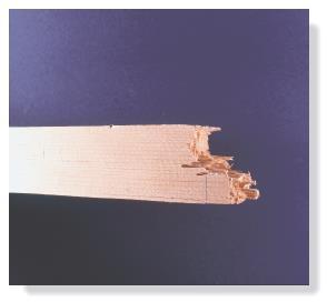
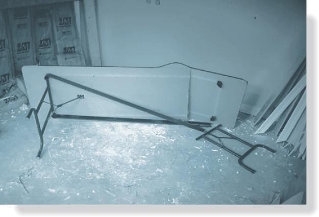
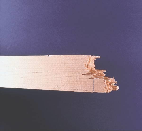
 DESIGN OF EAMS AND SHAFTS! asis for eam Design! Stress Variations Throughout a Prismatic eam! Design of pristmatic beams! Steel beams! Wooden beams! Design of Shaft! ombined bending! Torsion 1 asis for
Chapter 7 FORCES IN BEAMS AND CABLES
 hapter 7 FORES IN BEAMS AN ABLES onsider a straight two-force member AB subjected at A and B to equal and opposite forces F and -F directed along AB. utting the member AB at and drawing the free-body B
CHAPTER THREE SYMMETRIC BENDING OF CIRCLE PLATES
 CHAPTER THREE SYMMETRIC BENDING OF CIRCLE PLATES * Governing equations in beam and plate bending ** Solution by superposition 1.1 From Beam Bending to Plate Bending 1.2 Governing Equations For Symmetric
MECHANICS LAB AM 317 EXP 3 BENDING STRESS IN A BEAM
 MECHANICS LAB AM 37 EXP 3 BENDING STRESS IN A BEAM I. OBJECTIVES I. To compare the experimentally determined stresses in a beam with those predicted from the simple beam theory (a.k.a. Euler-Bernoull beam
Unit Workbook 1 Level 4 ENG U8 Mechanical Principles 2018 UniCourse Ltd. All Rights Reserved. Sample
 Pearson BTEC Levels 4 Higher Nationals in Engineering (RQF) Unit 8: Mechanical Principles Unit Workbook 1 in a series of 4 for this unit Learning Outcome 1 Static Mechanical Systems Page 1 of 23 1.1 Shafts
ME 176 Final Exam, Fall 1995
 ME 176 Final Exam, Fall 1995 Saturday, December 16, 12:30 3:30 PM, 1995. Answer all questions. Please write all answers in the space provided. If you need additional space, write on the back sides. Indicate
CHAPTER 4: BENDING OF BEAMS
 (74) CHAPTER 4: BENDING OF BEAMS This chapter will be devoted to the analysis of prismatic members subjected to equal and opposite couples M and M' acting in the same longitudinal plane. Such members are
Solution: The moment of inertia for the cross-section is: ANS: ANS: Problem 15.6 The material of the beam in Problem
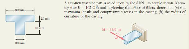
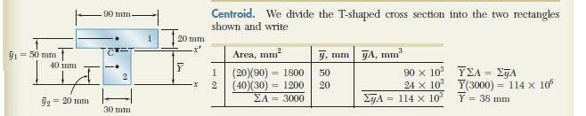
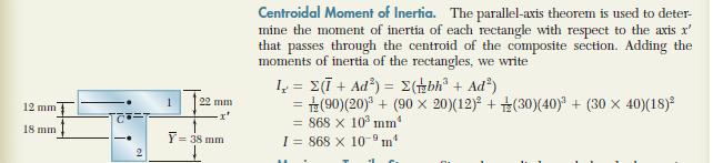
 Problem 15.4 The beam consists of material with modulus of elasticity E 14x10 6 psi and is subjected to couples M 150, 000 in lb at its ends. (a) What is the resulting radius of curvature of the neutral
7.4 The Elementary Beam Theory
 7.4 The Elementary Beam Theory In this section, problems involving long and slender beams are addressed. s with pressure vessels, the geometry of the beam, and the specific type of loading which will be
Finite Element Analysis Prof. Dr. B. N. Rao Department of Civil Engineering Indian Institute of Technology, Madras. Module - 01 Lecture - 11
 Finite Element Analysis Prof. Dr. B. N. Rao Department of Civil Engineering Indian Institute of Technology, Madras Module - 01 Lecture - 11 Last class, what we did is, we looked at a method called superposition
Procedure for drawing shear force and bending moment diagram:
 Procedure for drawing shear force and bending moment diagram: Preamble: The advantage of plotting a variation of shear force F and bending moment M in a beam as a function of x' measured from one end of
Russell C. Hibbeler. Chapter 1: Stress
 Russell C. Hibbeler Chapter 1: Stress Introduction Mechanics of materials is a study of the relationship between the external loads on a body and the intensity of the internal loads within the body. This
Beams. Beams are structural members that offer resistance to bending due to applied load
 Beams Beams are structural members that offer resistance to bending due to applied load 1 Beams Long prismatic members Non-prismatic sections also possible Each cross-section dimension Length of member
REVIEW FOR EXAM II. Dr. Ibrahim A. Assakkaf SPRING 2002
 REVIEW FOR EXM II. J. Clark School of Engineering Department of Civil and Environmental Engineering b Dr. Ibrahim. ssakkaf SPRING 00 ENES 0 Mechanics of Materials Department of Civil and Environmental
Shear Force and Bending Moment Diagrams
 Shear Force and Bending Moment Diagrams V [ N ] x[m] M [ Nm] x[m] Competencies 1. Draw shear force and bending moment diagrams for point loads and distributed loads 2. Recognize the position of maximum
The problem of transmitting a torque or rotary motion from one plane to another is frequently encountered in machine design.
 CHAPER ORSION ORSION orsion refers to the twisting of a structural member when it is loaded by moments/torques that produce rotation about the longitudinal axis of the member he problem of transmitting
Problem 1: Calculating deflection by integration uniform load. Problem 2: Calculating deflection by integration - triangular load pattern
 Problem 1: Calculating deflection by integration uniform load Problem 2: Calculating deflection by integration - triangular load pattern Problem 3: Deflections - by differential equations, concentrated
UNIT 1 STRESS STRAIN AND DEFORMATION OF SOLIDS, STATES OF STRESS 1. Define stress. When an external force acts on a body, it undergoes deformation.
 UNIT 1 STRESS STRAIN AND DEFORMATION OF SOLIDS, STATES OF STRESS 1. Define stress. When an external force acts on a body, it undergoes deformation. At the same time the body resists deformation. The magnitude
7.6 Stress in symmetrical elastic beam transmitting both shear force and bending moment
 7.6 Stress in symmetrical elastic beam transmitting both shear force and bending moment à It is more difficult to obtain an exact solution to this problem since the presence of the shear force means that
CIVL222 STRENGTH OF MATERIALS. Chapter 6. Torsion
 CIVL222 STRENGTH OF MATERIALS Chapter 6 Torsion Definition Torque is a moment that tends to twist a member about its longitudinal axis. Slender members subjected to a twisting load are said to be in torsion.
Chapter Objectives. Design a beam to resist both bendingand shear loads
 Chapter Objectives Design a beam to resist both bendingand shear loads A Bridge Deck under Bending Action Castellated Beams Post-tensioned Concrete Beam Lateral Distortion of a Beam Due to Lateral Load
Hong Kong Institute of Vocational Education (Tsing Yi) Higher Diploma in Civil Engineering Structural Mechanics. Chapter 2 SECTION PROPERTIES
 Higher Diploma in Civil Engineering Structural Mechanics. Chapter 2 SECTION PROPERTIES") Section Properties Centroid The centroid of an area is the point about which the area could be balanced if it was supported from that point. The word is derived from the word center, and it can be though
Section Properties Centroid The centroid of an area is the point about which the area could be balanced if it was supported from that point. The word is derived from the word center, and it can be though
AREAS, RADIUS OF GYRATION
 Chapter 10 MOMENTS of INERTIA for AREAS, RADIUS OF GYRATION Today s Objectives: Students will be able to: a) Define the moments of inertia (MoI) for an area. b) Determine the MoI for an area by integration.
Beams are bars of material that support. Beams are common structural members. Beams can support both concentrated and distributed loads
 Outline: Review External Effects on Beams Beams Internal Effects Sign Convention Shear Force and Bending Moment Diagrams (text method) Relationships between Loading, Shear Force and Bending Moments (faster
Structural Analysis I Chapter 4 - Torsion TORSION
 ORSION orsional stress results from the action of torsional or twisting moments acting about the longitudinal axis of a shaft. he effect of the application of a torsional moment, combined with appropriate
Chapter 7: Bending and Shear in Simple Beams
 Chapter 7: Bending and Shear in Simple Beams Introduction A beam is a long, slender structural member that resists loads that are generally applied transverse (perpendicular) to its longitudinal axis.
5. What is the moment of inertia about the x - x axis of the rectangular beam shown?
 1 of 5 Continuing Education Course #274 What Every Engineer Should Know About Structures Part D - Bending Strength Of Materials NOTE: The following question was revised on 15 August 2018 1. The moment
EMA 3702 Mechanics & Materials Science (Mechanics of Materials) Chapter 5 Beams for Bending
 Chapter 5 Beams for Bending") MA 3702 Mechanics & Materials Science (Mechanics of Materials) Chapter 5 Beams for Bending Introduction esign of beams for mechanical or civil/structural applications Transverse loading in most cases for
MA 3702 Mechanics & Materials Science (Mechanics of Materials) Chapter 5 Beams for Bending Introduction esign of beams for mechanical or civil/structural applications Transverse loading in most cases for
Chapter 6: Cross-Sectional Properties of Structural Members
 Chapter 6: Cross-Sectional Properties of Structural Members Introduction Beam design requires the knowledge of the following. Material strengths (allowable stresses) Critical shear and moment values Cross
BEAMS: SHEAR AND MOMENT DIAGRAMS (FORMULA)
") LETURE Third Edition BEMS: SHER ND MOMENT DGRMS (FORMUL). J. lark School of Engineering Department of ivil and Environmental Engineering 1 hapter 5.1 5. b Dr. brahim. ssakkaf SPRNG 00 ENES 0 Mechanics
LETURE Third Edition BEMS: SHER ND MOMENT DGRMS (FORMUL). J. lark School of Engineering Department of ivil and Environmental Engineering 1 hapter 5.1 5. b Dr. brahim. ssakkaf SPRNG 00 ENES 0 Mechanics
Chapter 4 Deflection and Stiffness
 Chapter 4 Deflection and Stiffness Asst. Prof. Dr. Supakit Rooppakhun Chapter Outline Deflection and Stiffness 4-1 Spring Rates 4-2 Tension, Compression, and Torsion 4-3 Deflection Due to Bending 4-4 Beam
Application of Finite Element Method to Create Animated Simulation of Beam Analysis for the Course of Mechanics of Materials
 International Conference on Engineering Education and Research "Progress Through Partnership" 4 VSB-TUO, Ostrava, ISSN 156-35 Application of Finite Element Method to Create Animated Simulation of Beam
twenty one concrete construction: shear & deflection ARCHITECTURAL STRUCTURES: FORM, BEHAVIOR, AND DESIGN DR. ANNE NICHOLS SUMMER 2014 lecture
 ARCHITECTURAL STRUCTURES: FORM, BEHAVIOR, AND DESIGN DR. ANNE NICHOLS SUMMER 2014 lecture twenty one concrete construction: Copyright Kirk Martini shear & deflection Concrete Shear 1 Shear in Concrete
Mechanics of Structure
 S.Y. Diploma : Sem. III [CE/CS/CR/CV] Mechanics of Structure Time: Hrs.] Prelim Question Paper Solution [Marks : 70 Q.1(a) Attempt any SIX of the following. [1] Q.1(a) Define moment of Inertia. State MI
CHAPTER 4. Stresses in Beams
 CHAPTER 4 Stresses in Beams Problem 1. A rolled steel joint (RSJ) of -section has top and bottom flanges 150 mm 5 mm and web of size 00 mm 1 mm. t is used as a simply supported beam over a span of 4 m
DEPARTMENT OF CIVIL ENGINEERING
 KINGS COLLEGE OF ENGINEERING DEPARTMENT OF CIVIL ENGINEERING SUBJECT: CE 2252 STRENGTH OF MATERIALS UNIT: I ENERGY METHODS 1. Define: Strain Energy When an elastic body is under the action of external
Purpose of this Guide: To thoroughly prepare students for the exact types of problems that will be on Exam 3.
 ES230 STRENGTH OF MTERILS Exam 3 Study Guide Exam 3: Wednesday, March 8 th in-class Updated 3/3/17 Purpose of this Guide: To thoroughly prepare students for the exact types of problems that will be on
MINISTRY OF EDUCATION AND SCIENCE OF UKRAINE. National aerospace university Kharkiv Aviation Institute. Department of aircraft strength
 MINISTRY OF EDUCATION AND SCIENCE OF UKRAINE National aerospace university Kharkiv Aviation Institute Department of aircraft strength Course Mechanics of materials and structures HOME PROBLEM 8 Strength
Module 3. Analysis of Statically Indeterminate Structures by the Displacement Method
 odule 3 Analysis of Statically Indeterminate Structures by the Displacement ethod Lesson 21 The oment- Distribution ethod: rames with Sidesway Instructional Objectives After reading this chapter the student
Mechanical Design in Optical Engineering
 OPTI Buckling Buckling and Stability: As we learned in the previous lectures, structures may fail in a variety of ways, depending on the materials, load and support conditions. We had two primary concerns:
Comb resonator design (2)
") Lecture 6: Comb resonator design () -Intro Intro. to Mechanics of Materials School of Electrical l Engineering i and Computer Science, Seoul National University Nano/Micro Systems & Controls Laboratory
Lecture 6: Comb resonator design () -Intro Intro. to Mechanics of Materials School of Electrical l Engineering i and Computer Science, Seoul National University Nano/Micro Systems & Controls Laboratory
MECHANICS OF MATERIALS
 STATICS AND MECHANICS OF MATERIALS Ferdinand P. Beer E. Russell Johnston, Jr, John T. DeWolf David E Mazurek \Cawect Mc / iur/» Craw SugomcT Hilt Introduction 1 1.1 What is Mechanics? 2 1.2 Fundamental
needed to buckle an ideal column. Analyze the buckling with bending of a column. Discuss methods used to design concentric and eccentric columns.
 CHAPTER OBJECTIVES Discuss the behavior of columns. Discuss the buckling of columns. Determine the axial load needed to buckle an ideal column. Analyze the buckling with bending of a column. Discuss methods
PLAT DAN CANGKANG (TKS 4219)
") PLAT DAN CANGKANG (TKS 4219) SESI I: PLATES Dr.Eng. Achfas Zacoeb Dept. of Civil Engineering Brawijaya University INTRODUCTION Plates are straight, plane, two-dimensional structural components of which
PLAT DAN CANGKANG (TKS 4219) SESI I: PLATES Dr.Eng. Achfas Zacoeb Dept. of Civil Engineering Brawijaya University INTRODUCTION Plates are straight, plane, two-dimensional structural components of which
By Dr. Mohammed Ramidh
 Engineering Materials Design Lecture.6 the design of beams By Dr. Mohammed Ramidh 6.1 INTRODUCTION Finding the shear forces and bending moments is an essential step in the design of any beam. we usually
Structures. Shainal Sutaria
 Structures ST Shainal Sutaria Student Number: 1059965 Wednesday, 14 th Jan, 011 Abstract An experiment to find the characteristics of flow under a sluice gate with a hydraulic jump, also known as a standing
CH. 4 BEAMS & COLUMNS
 CH. 4 BEAMS & COLUMNS BEAMS Beams Basic theory of bending: internal resisting moment at any point in a beam must equal the bending moments produced by the external loads on the beam Rx = Cc + Tt - If the
STRENGTH OF MATERIALS-I. Unit-1. Simple stresses and strains
 STRENGTH OF MATERIALS-I Unit-1 Simple stresses and strains 1. What is the Principle of surveying 2. Define Magnetic, True & Arbitrary Meridians. 3. Mention different types of chains 4. Differentiate between
Chapter 3. Load and Stress Analysis
 Chapter 3 Load and Stress Analysis 2 Shear Force and Bending Moments in Beams Internal shear force V & bending moment M must ensure equilibrium Fig. 3 2 Sign Conventions for Bending and Shear Fig. 3 3
Consider an elastic spring as shown in the Fig.2.4. When the spring is slowly
 .3 Strain Energy Consider an elastic spring as shown in the Fig..4. When the spring is slowly pulled, it deflects by a small amount u 1. When the load is removed from the spring, it goes back to the original