CHAPTER -6- BENDING Part -1-
|
|
|
- Dorothy Charles
- 6 years ago
- Views:
Transcription
1 Ishik University / Sulaimani Civil Engineering Department Mechanics of Materials CE 211 CHAPTER -6- BENDING Part -1-1 CHAPTER -6- Bending Outlines of this chapter: 6.1. Chapter Objectives 6.2. Shear and Moment Diagrams 6.3. Graphical Method for Constructing Shear and Moment Diagrams 6.4. Bending Deformation of a Straight Member 6.5. The Flexure Formula 2 1


2 6.1. Chapter Objectives Determine stress in members caused by bending. Discuss how to establish shear and moment diagrams for a beam or shaft. Determine largest shear and moment in a member, and specify where they occur. Consider members that are straight, symmetric x- section and homogeneous linear-elastic material. 3 Chapter Objectives Members that are slender and support loadings applied perpendicular to their longitudinal axis are called beams. 4 2

3 Regions of distributed load 5 6 3

4 6.2. Shear and Moment Diagrams Shear and bending-moment functions must be determined for each region of the beam between any two discontinuities of loading 7 Beam sign convention Although choice of sign convention is arbitrary, in this course, we adopt the one often used by engineers: 8 4
5 IMPORTANT Beams are long straight members that carry loads perpendicular to their longitudinal axis. They are classified according to how they are supported to design a beam, we need to know the variation of the shear and moment along its axis in order to find the points where they are maximum establishing a sign convention for positive shear and moment will allow us to draw the shear and moment diagrams Graphical Method for Constructing Shear and Moment Diagrams In order to design a beam, it is necessary to determine the maximum shear and moment in the beam. Express V and M as functions of arbitrary position x along axis. These functions can be represented by graphs called shear and moment diagrams. Engineers need to know the variation of shear and moment along the beam to know where to reinforce it. 10 5
6 Procedure for analysis Support reactions Determine all reactive forces and couple moments acting on beam Resolve all forces into components acting perpendicular and parallel to beam s axis Shear and moment functions Specify separate coordinates x having an origin at beam s left end, and extending to regions of beam between concentrated forces and/or couple moments, or where there is no discontinuity of distributed loading 11 Section beam perpendicular to its axis at each distance x Draw free-body diagram of one segment. Make sure V and M are shown acting in positive sense, according to sign convention. Sum forces perpendicular to beam s axis to get shear Sum moments about the sectioned end of segment to get moment. Shear and moment diagrams Plot shear diagram (V vs. x) and moment diagram (M vs. x) If numerical values are positive, values are plotted above axis, otherwise, negative values are plotted below axis It is convenient to show the shear and moment diagrams directly below the free-body diagram 12 6

7 Example 1. Draw the shear and moment diagrams for the beam shown in Fig. 13 Solution; 14 7
8


9 Example 2. Draw the shear and moment diagrams for the overhang beam in fig. 17 Solution; 18 9


10 19 Mechanics of Materials, 8 th Edition, R.C. Hibbeler Chapter -6-, Fundamental Problems, F6-1, F6-2, F6-3, F6-4, F6-5, F6-6, F6-7, F6-8, F6-9, F6-10, F6-11, F6-12, F6-13, F6-14 Problems 6.1, 6.2, 6.3, 6.4, 6.5, 6.6, 6.7, 6.8, 6.9, 6.10, 6.11, 6.12, 6.13, 6.14, 6.15, 6.16, 6.17, 6.18, 6.19, 6.20, 6.21, 6.22, 6.29, 6.30, 6.33, 6.34, 6.35, 6.36, 6.37, 6.38, 6.40, 6.41, 6.42,


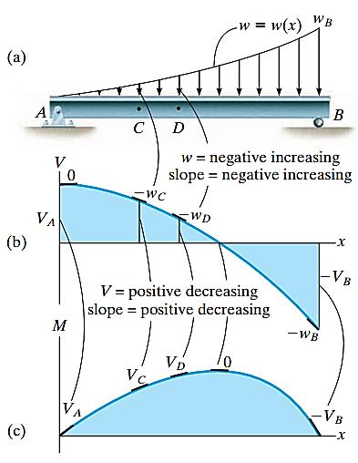
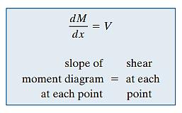
11 A simpler method to construct shear and moment diagram, one that is based on two differential equations that exist among distributed load, shear and moment. Regions of concentrated force and moment 21 Regions of concentrated force and moment 22 11
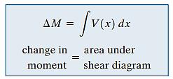
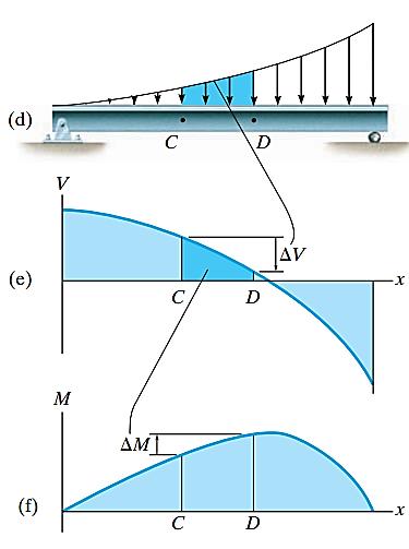
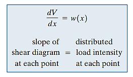
12 Support reactions Procedure for analysis Determine support reactions and resolve forces acting on the beam into components that are perpendicular and parallel to beam s axis. Shear diagram Establish V and x axes Plot known values of shear at two ends of the beam. Shear diagram Procedure for analysis Since dv/dx = w, slope of the shear diagram at any point is equal to the (-ve) intensity of the distributed loading at that point. To find numerical value of shear at a point, use method of sections and equation of equilibrium or by using V = w(x) dx, i.e., change in the shear between any two points is equal to (-ve) area under the load diagram between the two points. 23 Shear diagram Procedure for analysis Since w(x) must be integrated to obtain V, then if w(x) is a curve of degree n, V(x) will be a curve of degree n+1 Moment diagram Establish M and x axes and plot known values of the moment at the ends of the beam Since dm/dx = V, slope of the moment diagram at any point is equal to the shear at the point At point where shear is zero, dm/dx = 0 and therefore this will be a point of maximum or minimum moment If numerical value of moment is to be determined at the point, use method of sections and equation of equilibrium, or by using M = V(x) dx, i.e., change in moment between any two pts is equal to area under shear diagram between the two pts. Since V(x) must be integrated to obtain M, then if V(x) is a curve of degree n, M(x) will be a curve of degree n


13 Example 3. Draw the shear and moment diagrams for beam shown below. 25 Solution; Support reactions: See free-body diagram. Shear diagram From behavior of distributed load, slope of shear diagram varies from zero at x = 0 to 2 at x = 4.5. Thus, its parabolic shape. Use method of sections to find point of zero shear: + F y = 0;... x = 2.6 m 26 13


14 Solution; Moment diagram From shear diagram, slope of moment diagram begin at +1.5, then decreases positively till it reaches zero at 2.6 m. Then it increases negatively and reaches 3 at x = 4.5 m. Moment diagram is a cubic function of x Bending Deformation of a Straight Member When a bending moment is applied to a straight prismatic beam, the longitudinal lines become curved and vertical transverse lines remain straight and yet undergo a rotation 28 14


15 29 Bending Deformation of a Straight Member A neutral surface is where longitudinal fibers of the material will not undergo a change in length
16 Thus, we make the following assumptions: 1. Longitudinal axis x (within neutral surface) does not experience any change in length. 2. All cross sections of the beam remain plane and perpendicular to longitudinal axis during the deformation. 3. Any deformation of the cross-section within its own plane will be neglected. In particular, the z axis, in plane of x-section and about which the x-section rotates, is called the neutral axis. For any specific x-section, the longitudinal normal strain will vary linearly with y from the neutral axis A contraction will occur ( ) in fibers located above the neutral axis (+y). An elongation will occur (+ ) in fibers located below the axis ( y). 31 s' s lim s s 0 ( lim s 0 Radius of curvature y) Length decreases y Length = constant 32 16

17 Equation 6-8 = (y/c) max Says normal strain is linear Maximum at outer surface (where y = c) y The Flexure Formula Assume that material behaves in a linear-elastic manner so that Hooke s law applies. A linear variation of normal strain must then be the consequence of a linear variation in normal stress Applying Hooke s law to Eqn 6-8, Equation 6-9 = (y/c) max 34 17

18 By mathematical expression, equilibrium equations of moment and forces, we get Equation 6-10 Equation 6-11 A y da = 0 M = max c A y 2 da The integral represents the moment of inertia of x- sectional area, computed about the neutral axis. We symbolize its value as I. 35 Hence, Eqn 6-11 can be solved and written as Equation 6-12 max = Mc I max = maximum normal stress in member, at a pt on x- sectional area farthest away from neutral axis M = resultant internal moment, computed about neutral axis of x-section I = moment of inertia of x-sectional area computed about neutral axis c = perpendicular distance from neutral axis to a pt farthest away from neutral axis, where max acts 36 18
19 Normal stress at intermediate distance y can be determined from Equation 6-13 = My I is -ve as it acts in the -ve direction (compression) Equations 6-12 and 6-13 are often referred to as the flexure formula. 37 The Flexure Formula IMPORTANT X-section of straight beam remains plane when beam deforms due to bending. The neutral axis is subjected to zero stress Due to deformation, longitudinal strain varies linearly from zero at neutral axis to maximum at outer fibers of beam Provided material is homogeneous and Hooke s law applies, stress also varies linearly over the x-section 38 19
20 The Flexure Formula IMPORTANT For linear-elastic material, neutral axis passes through centroid of x-sectional area. This is based on the fact that resultant normal force acting on x- section must be zero Flexure formula is based on requirement that resultant moment on the x-section is equal to moment produced by linear normal stress distribution about neutral axis 39 The Flexure Formula Procedure for analysis Internal moment Section member at pt where bending or normal stress is to be determined and obtain internal moment M at the section Centroidal or neutral axis for x-section must be known since M is computed about this axis If absolute maximum bending stress is to be determined, then draw moment diagram in order to determine the maximum moment in the diagram 40 20
21 The Flexure Formula Procedure for analysis Section property Determine moment of inertia I, of x-sectional area about the neutral axis Methods used are discussed in Textbook Appendix A Refer to the course book s inside front cover for the values of I for several common shapes 41 Procedure for analysis Normal stress Specify distance y, measured perpendicular to neutral axis to pt where normal stress is to be determined Apply equation = My/I, or if maximum bending stress is needed, use max = Mc/I Ensure units are consistent when substituting values into the equations 42 21


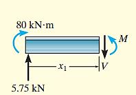
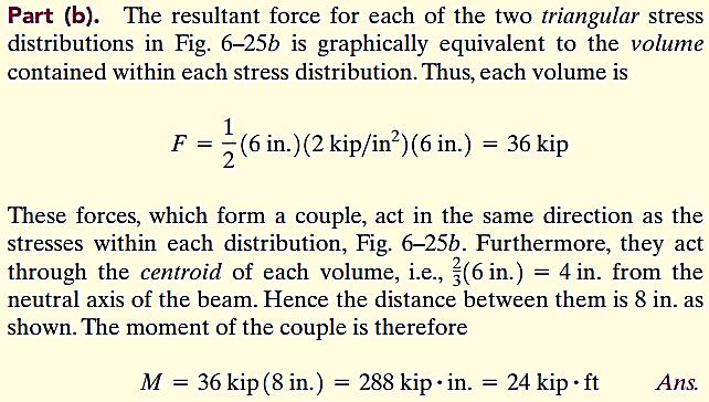
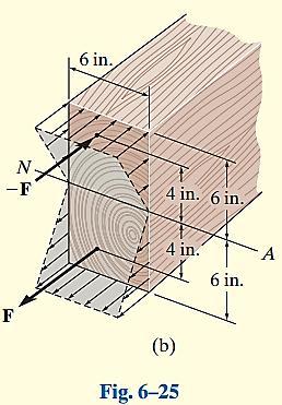
22 Example 4. A beam has a rectangular cross section and is subjected to the stress shown in Fig. 6 25a. Determine the internal moment M at the section caused by the stress distribution, (a) using the flexure formula, (b) by finding the resultant of the stress distribution using basic principles
23


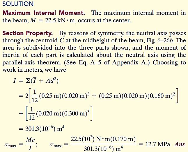
24 Example 5. The simply supported beam in Fig. 6 26a has the crosssectional area shown in Fig. 6 26b. Determine the absolute maximum bending stress in the beam and draw the stress distribution over the cross section at this location

25


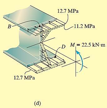
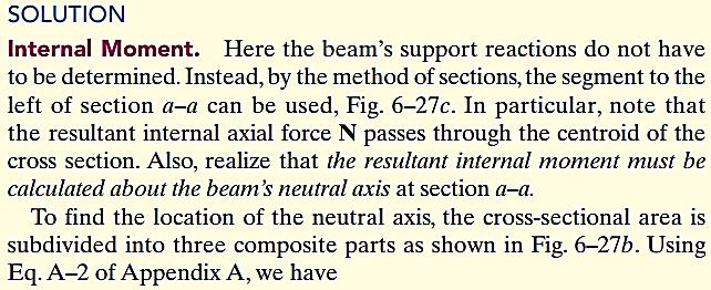
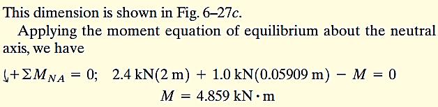
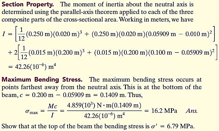
26 51 Example 6. The beam shown in Fig. 6 27a has a cross-sectional area in the shape of a channel, Fig. 6 27b. Determine the maximum bending stress that occurs in the beam at section a a 52 26
27


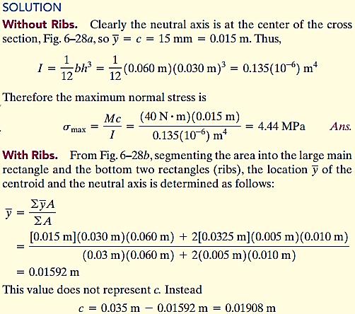
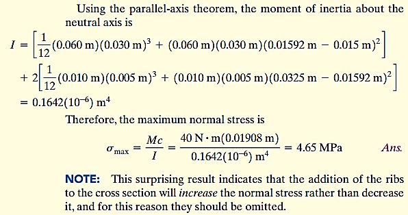
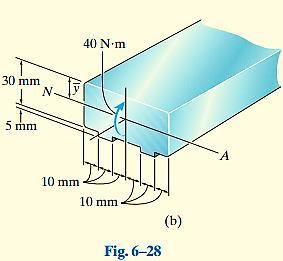
28 55 Example 7. The member having a rectangular cross section, Fig. 6 28a, is designed to resist a moment of In order to increase its strength and rigidity, it is proposed that two small ribs be added at its bottom, Fig. 6 28b. Determine the maximum normal stress in the member for both cases
29
30 Mechanics of Materials, 8 th Edition, R.C. Hibbeler Chapter -6-, Fundamental Problems, F6-15, F6-16, F6-17, F6-18, F6-19 Problems 6.47, 6.48, 6.49, 6.50, 6.51, 6.52, 6.53, 6.54, 6.55, 6.56, 6.57, 6.58, 6.59, 6.60, 6.61, 6.62, 6.65, 6.66, 6.67, 6.68, 6.85, 6.99, 6.105, References; Mechanics of Materials, 8 th Edition, R.C. Hibbeler 60 30
6. Bending CHAPTER OBJECTIVES
 CHAPTER OBJECTIVES Determine stress in members caused by bending Discuss how to establish shear and moment diagrams for a beam or shaft Determine largest shear and moment in a member, and specify where
[8] Bending and Shear Loading of Beams
![[8] Bending and Shear Loading of Beams](/thumbs/92/110949676.jpg "[8] Bending and Shear Loading of Beams") [8] Bending and Shear Loading of Beams Page 1 of 28 [8] Bending and Shear Loading of Beams [8.1] Bending of Beams (will not be covered in class) [8.2] Bending Strain and Stress [8.3] Shear in Straight
[8] Bending and Shear Loading of Beams Page 1 of 28 [8] Bending and Shear Loading of Beams [8.1] Bending of Beams (will not be covered in class) [8.2] Bending Strain and Stress [8.3] Shear in Straight
MECE 3321: Mechanics of Solids Chapter 6
 MECE 3321: Mechanics of Solids Chapter 6 Samantha Ramirez Beams Beams are long straight members that carry loads perpendicular to their longitudinal axis Beams are classified by the way they are supported
Chapter Objectives. Copyright 2011 Pearson Education South Asia Pte Ltd
 Chapter Objectives To generalize the procedure by formulating equations that can be plotted so that they describe the internal shear and moment throughout a member. To use the relations between distributed
PURE BENDING. If a simply supported beam carries two point loads of 10 kn as shown in the following figure, pure bending occurs at segment BC.
 BENDING STRESS The effect of a bending moment applied to a cross-section of a beam is to induce a state of stress across that section. These stresses are known as bending stresses and they act normally
MECHANICS OF MATERIALS. Analysis of Beams for Bending
 MECHANICS OF MATERIALS Analysis of Beams for Bending By NUR FARHAYU ARIFFIN Faculty of Civil Engineering & Earth Resources Chapter Description Expected Outcomes Define the elastic deformation of an axially
CHAPTER OBJECTIVES Use various methods to determine the deflection and slope at specific pts on beams and shafts: 2. Discontinuity functions
 1. Deflections of Beams and Shafts CHAPTER OBJECTIVES Use various methods to determine the deflection and slope at specific pts on beams and shafts: 1. Integration method. Discontinuity functions 3. Method
Lecture 15 Strain and stress in beams
 Spring, 2019 ME 323 Mechanics of Materials Lecture 15 Strain and stress in beams Reading assignment: 6.1 6.2 News: Instructor: Prof. Marcial Gonzalez Last modified: 1/6/19 9:42:38 PM Beam theory (@ ME
7 TRANSVERSE SHEAR transverse shear stress longitudinal shear stresses
 7 TRANSVERSE SHEAR Before we develop a relationship that describes the shear-stress distribution over the cross section of a beam, we will make some preliminary remarks regarding the way shear acts within
Stress Analysis Lecture 4 ME 276 Spring Dr./ Ahmed Mohamed Nagib Elmekawy
 Stress Analysis Lecture 4 ME 76 Spring 017-018 Dr./ Ahmed Mohamed Nagib Elmekawy Shear and Moment Diagrams Beam Sign Convention The positive directions are as follows: The internal shear force causes a
Samantha Ramirez, MSE
 Samantha Ramirez, MSE Centroids The centroid of an area refers to the point that defines the geometric center for the area. In cases where the area has an axis of symmetry, the centroid will lie along
3. BEAMS: STRAIN, STRESS, DEFLECTIONS
 3. BEAMS: STRAIN, STRESS, DEFLECTIONS The beam, or flexural member, is frequently encountered in structures and machines, and its elementary stress analysis constitutes one of the more interesting facets
Mechanics in Energy Resources Engineering - Chapter 5 Stresses in Beams (Basic topics)
") Week 7, 14 March Mechanics in Energy Resources Engineering - Chapter 5 Stresses in Beams (Basic topics) Ki-Bok Min, PhD Assistant Professor Energy Resources Engineering i Seoul National University Shear
Week 7, 14 March Mechanics in Energy Resources Engineering - Chapter 5 Stresses in Beams (Basic topics) Ki-Bok Min, PhD Assistant Professor Energy Resources Engineering i Seoul National University Shear
Consider an elastic spring as shown in the Fig.2.4. When the spring is slowly
 .3 Strain Energy Consider an elastic spring as shown in the Fig..4. When the spring is slowly pulled, it deflects by a small amount u 1. When the load is removed from the spring, it goes back to the original
Advanced Structural Analysis EGF Section Properties and Bending
 Advanced Structural Analysis EGF316 3. Section Properties and Bending 3.1 Loads in beams When we analyse beams, we need to consider various types of loads acting on them, for example, axial forces, shear
Chapter 3. Load and Stress Analysis
 Chapter 3 Load and Stress Analysis 2 Shear Force and Bending Moments in Beams Internal shear force V & bending moment M must ensure equilibrium Fig. 3 2 Sign Conventions for Bending and Shear Fig. 3 3
Stresses in Curved Beam
 Stresses in Curved Beam Consider a curved beam subjected to bending moment M b as shown in the figure. The distribution of stress in curved flexural member is determined by using the following assumptions:
MECHANICS LAB AM 317 EXP 3 BENDING STRESS IN A BEAM
 MECHANICS LAB AM 37 EXP 3 BENDING STRESS IN A BEAM I. OBJECTIVES I. To compare the experimentally determined stresses in a beam with those predicted from the simple beam theory (a.k.a. Euler-Bernoull beam
Strength of Materials Prof. S.K.Bhattacharya Dept. of Civil Engineering, I.I.T., Kharagpur Lecture No.26 Stresses in Beams-I
 Strength of Materials Prof. S.K.Bhattacharya Dept. of Civil Engineering, I.I.T., Kharagpur Lecture No.26 Stresses in Beams-I Welcome to the first lesson of the 6th module which is on Stresses in Beams
BEAM DEFLECTION THE ELASTIC CURVE
 BEAM DEFLECTION Samantha Ramirez THE ELASTIC CURVE The deflection diagram of the longitudinal axis that passes through the centroid of each cross-sectional area of a beam. Supports that apply a moment
4. BEAMS: CURVED, COMPOSITE, UNSYMMETRICAL
 4. BEMS: CURVED, COMPOSITE, UNSYMMETRICL Discussions of beams in bending are usually limited to beams with at least one longitudinal plane of symmetry with the load applied in the plane of symmetry or
Chapter 3. Load and Stress Analysis. Lecture Slides
 Lecture Slides Chapter 3 Load and Stress Analysis 2015 by McGraw Hill Education. This is proprietary material solely for authorized instructor use. Not authorized for sale or distribution in any manner.
Chapter 4 Deflection and Stiffness
 Chapter 4 Deflection and Stiffness Asst. Prof. Dr. Supakit Rooppakhun Chapter Outline Deflection and Stiffness 4-1 Spring Rates 4-2 Tension, Compression, and Torsion 4-3 Deflection Due to Bending 4-4 Beam
Mechanics of Solids notes
 Mechanics of Solids notes 1 UNIT II Pure Bending Loading restrictions: As we are aware of the fact internal reactions developed on any cross-section of a beam may consists of a resultant normal force,
Mechanics of Materials II. Chapter III. A review of the fundamental formulation of stress, strain, and deflection
 Mechanics of Materials II Chapter III A review of the fundamental formulation of stress, strain, and deflection Outline Introduction Assumtions and limitations Axial loading Torsion of circular shafts
Strength of Materials II (Mechanics of Materials) (SI Units) Dr. Ashraf Alfeehan
 (SI Units) Dr. Ashraf Alfeehan") Strength of Materials II (Mechanics of Materials) (SI Units) Dr. Ashraf Alfeehan 2017-2018 Mechanics of Material II Text Books Mechanics of Materials, 10th edition (SI version), by: R. C. Hibbeler, 2017
Strength of Materials II (Mechanics of Materials) (SI Units) Dr. Ashraf Alfeehan 2017-2018 Mechanics of Material II Text Books Mechanics of Materials, 10th edition (SI version), by: R. C. Hibbeler, 2017
공업역학/ 일반물리1 수강대상기계공학과 2학년
 교과목명 ( 국문) 고체역학 ( 영문) Solid Mechanics 담당교수( 소속) 박주혁( 기계공학과) 학수번호/ 구분/ 학점 004510/ 전필/3(3) 1반 전화( 연구실/HP) 3408-3771/010-6214-3771 강의시간/ 강의실화목9:00-10:15/ 충무관106 선수과목 공업역학/ 일반물리1 수강대상기계공학과 2학년 jhpark@sejong.ac.kr
Chapter 7: Internal Forces
 Chapter 7: Internal Forces Chapter Objectives To show how to use the method of sections for determining the internal loadings in a member. To generalize this procedure by formulating equations that can
Symmetric Bending of Beams
 Symmetric Bending of Beams beam is any long structural member on which loads act perpendicular to the longitudinal axis. Learning objectives Understand the theory, its limitations and its applications
7.6 Stress in symmetrical elastic beam transmitting both shear force and bending moment
 7.6 Stress in symmetrical elastic beam transmitting both shear force and bending moment à It is more difficult to obtain an exact solution to this problem since the presence of the shear force means that
Assumptions: beam is initially straight, is elastically deformed by the loads, such that the slope and deflection of the elastic curve are
 *12.4 SLOPE & DISPLACEMENT BY THE MOMENT-AREA METHOD Assumptions: beam is initially straight, is elastically deformed by the loads, such that the slope and deflection of the elastic curve are very small,
STRESS STRAIN AND DEFORMATION OF SOLIDS, STATES OF STRESS
 1 UNIT I STRESS STRAIN AND DEFORMATION OF SOLIDS, STATES OF STRESS 1. Define: Stress When an external force acts on a body, it undergoes deformation. At the same time the body resists deformation. The
Mechanical Design in Optical Engineering
 Torsion Torsion: Torsion refers to the twisting of a structural member that is loaded by couples (torque) that produce rotation about the member s longitudinal axis. In other words, the member is loaded
(Refer Slide Time: 01:00 01:01)
") Strength of Materials Prof: S.K.Bhattacharya Department of Civil Engineering Indian institute of Technology Kharagpur Lecture no 27 Lecture Title: Stresses in Beams- II Welcome to the second lesson of
Strength of Materials Prof: S.K.Bhattacharya Department of Civil Engineering Indian institute of Technology Kharagpur Lecture no 27 Lecture Title: Stresses in Beams- II Welcome to the second lesson of
Purpose of this Guide: To thoroughly prepare students for the exact types of problems that will be on Exam 3.
 ES230 STRENGTH OF MTERILS Exam 3 Study Guide Exam 3: Wednesday, March 8 th in-class Updated 3/3/17 Purpose of this Guide: To thoroughly prepare students for the exact types of problems that will be on
7.4 The Elementary Beam Theory
 7.4 The Elementary Beam Theory In this section, problems involving long and slender beams are addressed. s with pressure vessels, the geometry of the beam, and the specific type of loading which will be
Bending Stress. Sign convention. Centroid of an area
 Bending Stress Sign convention The positive shear force and bending moments are as shown in the figure. Centroid of an area Figure 40: Sign convention followed. If the area can be divided into n parts
Lab Exercise #5: Tension and Bending with Strain Gages
 Lab Exercise #5: Tension and Bending with Strain Gages Pre-lab assignment: Yes No Goals: 1. To evaluate tension and bending stress models and Hooke s Law. a. σ = Mc/I and σ = P/A 2. To determine material
Chapter 5 Torsion STRUCTURAL MECHANICS: CE203. Notes are based on Mechanics of Materials: by R. C. Hibbeler, 7th Edition, Pearson
 STRUCTURAL MECHANICS: CE203 Chapter 5 Torsion Notes are based on Mechanics of Materials: by R. C. Hibbeler, 7th Edition, Pearson Dr B. Achour & Dr Eng. K. El-kashif Civil Engineering Department, University
Chapter 7: Bending and Shear in Simple Beams
 Chapter 7: Bending and Shear in Simple Beams Introduction A beam is a long, slender structural member that resists loads that are generally applied transverse (perpendicular) to its longitudinal axis.
CHAPTER 4: BENDING OF BEAMS
 (74) CHAPTER 4: BENDING OF BEAMS This chapter will be devoted to the analysis of prismatic members subjected to equal and opposite couples M and M' acting in the same longitudinal plane. Such members are
Beam Bending Stresses and Shear Stress
 Beam Bending Stresses and Shear Stress Notation: A = name or area Aweb = area o the web o a wide lange section b = width o a rectangle = total width o material at a horizontal section c = largest distance
ENG2000 Chapter 7 Beams. ENG2000: R.I. Hornsey Beam: 1
 ENG2000 Chapter 7 Beams ENG2000: R.I. Hornsey Beam: 1 Overview In this chapter, we consider the stresses and moments present in loaded beams shear stress and bending moment diagrams We will also look at
PLAT DAN CANGKANG (TKS 4219)
") PLAT DAN CANGKANG (TKS 4219) SESI I: PLATES Dr.Eng. Achfas Zacoeb Dept. of Civil Engineering Brawijaya University INTRODUCTION Plates are straight, plane, two-dimensional structural components of which
PLAT DAN CANGKANG (TKS 4219) SESI I: PLATES Dr.Eng. Achfas Zacoeb Dept. of Civil Engineering Brawijaya University INTRODUCTION Plates are straight, plane, two-dimensional structural components of which
Mechanics of Materials
 Mechanics of Materials 2. Introduction Dr. Rami Zakaria References: 1. Engineering Mechanics: Statics, R.C. Hibbeler, 12 th ed, Pearson 2. Mechanics of Materials: R.C. Hibbeler, 9 th ed, Pearson 3. Mechanics
March 24, Chapter 4. Deflection and Stiffness. Dr. Mohammad Suliman Abuhaiba, PE
 Chapter 4 Deflection and Stiffness 1 2 Chapter Outline Spring Rates Tension, Compression, and Torsion Deflection Due to Bending Beam Deflection Methods Beam Deflections by Superposition Strain Energy Castigliano
Tuesday, February 11, Chapter 3. Load and Stress Analysis. Dr. Mohammad Suliman Abuhaiba, PE
 1 Chapter 3 Load and Stress Analysis 2 Chapter Outline Equilibrium & Free-Body Diagrams Shear Force and Bending Moments in Beams Singularity Functions Stress Cartesian Stress Components Mohr s Circle for
Chapter 5: Torsion. 1. Torsional Deformation of a Circular Shaft 2. The Torsion Formula 3. Power Transmission 4. Angle of Twist CHAPTER OBJECTIVES
 CHAPTER OBJECTIVES Chapter 5: Torsion Discuss effects of applying torsional loading to a long straight member (shaft or tube) Determine stress distribution within the member under torsional load Determine
1 Static Plastic Behaviour of Beams
 1 Static Plastic Behaviour of Beams 1.1 Introduction Many ductile materials which are used in engineering practice have a considerable reserve capacity beyond the initial yield condition. The uniaxial
CHAPTER THREE SYMMETRIC BENDING OF CIRCLE PLATES
 CHAPTER THREE SYMMETRIC BENDING OF CIRCLE PLATES * Governing equations in beam and plate bending ** Solution by superposition 1.1 From Beam Bending to Plate Bending 1.2 Governing Equations For Symmetric
Strength of Materials Prof: S.K.Bhattacharya Dept of Civil Engineering, IIT, Kharagpur Lecture no 28 Stresses in Beams- III
 Strength of Materials Prof: S.K.Bhattacharya Dept of Civil Engineering, IIT, Kharagpur Lecture no 28 Stresses in Beams- III Welcome to the 3 rd lesson of the 6 th module which is on Stresses in Beams part
Flexure: Behavior and Nominal Strength of Beam Sections
 4 5000 4000 (increased d ) (increased f (increased A s or f y ) c or b) Flexure: Behavior and Nominal Strength of Beam Sections Moment (kip-in.) 3000 2000 1000 0 0 (basic) (A s 0.5A s ) 0.0005 0.001 0.0015
Chapter 12 Plate Bending Elements. Chapter 12 Plate Bending Elements
 CIVL 7/8117 Chapter 12 - Plate Bending Elements 1/34 Chapter 12 Plate Bending Elements Learning Objectives To introduce basic concepts of plate bending. To derive a common plate bending element stiffness
CHAPTER 6: Shearing Stresses in Beams
 (130) CHAPTER 6: Shearing Stresses in Beams When a beam is in pure bending, the only stress resultants are the bending moments and the only stresses are the normal stresses acting on the cross sections.
Mechanics of Structure
 S.Y. Diploma : Sem. III [CE/CS/CR/CV] Mechanics of Structure Time: Hrs.] Prelim Question Paper Solution [Marks : 70 Q.1(a) Attempt any SIX of the following. [1] Q.1(a) Define moment of Inertia. State MI
Chapter 6: Cross-Sectional Properties of Structural Members
 Chapter 6: Cross-Sectional Properties of Structural Members Introduction Beam design requires the knowledge of the following. Material strengths (allowable stresses) Critical shear and moment values Cross
Finite Element Analysis Prof. Dr. B. N. Rao Department of Civil Engineering Indian Institute of Technology, Madras. Module - 01 Lecture - 11
 Finite Element Analysis Prof. Dr. B. N. Rao Department of Civil Engineering Indian Institute of Technology, Madras Module - 01 Lecture - 11 Last class, what we did is, we looked at a method called superposition
8. Combined Loadings
 CHAPTER OBJECTIVES qanalyze the stress developed in thin-walled pressure vessels qreview the stress analysis developed in previous chapters regarding axial load, torsion, bending and shear qdiscuss the
COURSE TITLE : THEORY OF STRUCTURES -I COURSE CODE : 3013 COURSE CATEGORY : B PERIODS/WEEK : 6 PERIODS/SEMESTER: 90 CREDITS : 6
 COURSE TITLE : THEORY OF STRUCTURES -I COURSE CODE : 0 COURSE CATEGORY : B PERIODS/WEEK : 6 PERIODS/SEMESTER: 90 CREDITS : 6 TIME SCHEDULE Module Topics Period Moment of forces Support reactions Centre
Mechanics of Materials Primer
 Mechanics of Materials rimer Notation: A = area (net = with holes, bearing = in contact, etc...) b = total width of material at a horizontal section d = diameter of a hole D = symbol for diameter E = modulus
UNSYMMETRICAL BENDING
 UNSYMMETRICAL BENDING The general bending stress equation for elastic, homogeneous beams is given as (II.1) where Mx and My are the bending moments about the x and y centroidal axes, respectively. Ix and
CHAPTER 5. Beam Theory
 CHPTER 5. Beam Theory SangJoon Shin School of Mechanical and erospace Engineering Seoul National University ctive eroelasticity and Rotorcraft Lab. 5. The Euler-Bernoulli assumptions One of its dimensions
EMA 3702 Mechanics & Materials Science (Mechanics of Materials) Chapter 6 Shearing Stress in Beams & Thin-Walled Members
 Chapter 6 Shearing Stress in Beams & Thin-Walled Members") EMA 3702 Mechanics & Materials Science (Mechanics of Materials) Chapter 6 Shearing Stress in Beams & Thin-Walled Members Beams Bending & Shearing EMA 3702 Mechanics & Materials Science Zhe Cheng (2018)
EMA 3702 Mechanics & Materials Science (Mechanics of Materials) Chapter 6 Shearing Stress in Beams & Thin-Walled Members Beams Bending & Shearing EMA 3702 Mechanics & Materials Science Zhe Cheng (2018)
dv dx Slope of the shear diagram = - Value of applied loading dm dx Slope of the moment curve = Shear Force
 Beams SFD and BMD Shear and Moment Relationships w dv dx Slope of the shear diagram = - Value of applied loading V dm dx Slope of the moment curve = Shear Force Both equations not applicable at the point
By Dr. Mohammed Ramidh
 Engineering Materials Design Lecture.6 the design of beams By Dr. Mohammed Ramidh 6.1 INTRODUCTION Finding the shear forces and bending moments is an essential step in the design of any beam. we usually
Chapter 5 Structural Elements: The truss & beam elements
 Institute of Structural Engineering Page 1 Chapter 5 Structural Elements: The truss & beam elements Institute of Structural Engineering Page 2 Chapter Goals Learn how to formulate the Finite Element Equations
Strength of Materials Prof. Dr. Suraj Prakash Harsha Mechanical and Industrial Engineering Department Indian Institute of Technology, Roorkee
 Strength of Materials Prof. Dr. Suraj Prakash Harsha Mechanical and Industrial Engineering Department Indian Institute of Technology, Roorkee Lecture - 28 Hi, this is Dr. S. P. Harsha from Mechanical and
Structural Dynamics Lecture Eleven: Dynamic Response of MDOF Systems: (Chapter 11) By: H. Ahmadian
 By: H. Ahmadian") Structural Dynamics Lecture Eleven: Dynamic Response of MDOF Systems: (Chapter 11) By: H. Ahmadian ahmadian@iust.ac.ir Dynamic Response of MDOF Systems: Mode-Superposition Method Mode-Superposition Method:
Structural Dynamics Lecture Eleven: Dynamic Response of MDOF Systems: (Chapter 11) By: H. Ahmadian ahmadian@iust.ac.ir Dynamic Response of MDOF Systems: Mode-Superposition Method Mode-Superposition Method:
Beams. Beams are structural members that offer resistance to bending due to applied load
 Beams Beams are structural members that offer resistance to bending due to applied load 1 Beams Long prismatic members Non-prismatic sections also possible Each cross-section dimension Length of member
Chapter 4.1: Shear and Moment Diagram
 Chapter 4.1: Shear and Moment Diagram Chapter 5: Stresses in Beams Chapter 6: Classical Methods Beam Types Generally, beams are classified according to how the beam is supported and according to crosssection
SIMPLY SUPPORTED STRUCTURAL BEAM STRESS AND DEFLECTION ANAL
 1 of 6 22/03/2016 09:17 HOMEPAGE CALCULATORS EXAMPLES GUIDELINES SIMPLY SUPPORTED STRUCTURAL BEAM STRESS AND DEFLECTION ANAL Following calculator has been developed to find forces, moments, stresses, deflections
M5 Simple Beam Theory (continued)
") M5 Simple Beam Theory (continued) Reading: Crandall, Dahl and Lardner 7.-7.6 In the previous lecture we had reached the point of obtaining 5 equations, 5 unknowns by application of equations of elasticity
M5 Simple Beam Theory (continued) Reading: Crandall, Dahl and Lardner 7.-7.6 In the previous lecture we had reached the point of obtaining 5 equations, 5 unknowns by application of equations of elasticity
CE 221: MECHANICS OF SOLIDS I CHAPTER 1: STRESS. Dr. Krisada Chaiyasarn Department of Civil Engineering, Faculty of Engineering Thammasat university
 CE 221: MECHANICS OF SOLIDS I CHAPTER 1: STRESS By Dr. Krisada Chaiyasarn Department of Civil Engineering, Faculty of Engineering Thammasat university Agenda Introduction to your lecturer Introduction
4.MECHANICAL PROPERTIES OF MATERIALS
 4.MECHANICAL PROPERTIES OF MATERIALS The diagram representing the relation between stress and strain in a given material is an important characteristic of the material. To obtain the stress-strain diagram
twenty one concrete construction: shear & deflection ARCHITECTURAL STRUCTURES: FORM, BEHAVIOR, AND DESIGN DR. ANNE NICHOLS SUMMER 2014 lecture
 ARCHITECTURAL STRUCTURES: FORM, BEHAVIOR, AND DESIGN DR. ANNE NICHOLS SUMMER 2014 lecture twenty one concrete construction: Copyright Kirk Martini shear & deflection Concrete Shear 1 Shear in Concrete
Application of Finite Element Method to Create Animated Simulation of Beam Analysis for the Course of Mechanics of Materials
 International Conference on Engineering Education and Research "Progress Through Partnership" 4 VSB-TUO, Ostrava, ISSN 156-35 Application of Finite Element Method to Create Animated Simulation of Beam
Sub. Code:
 Important Instructions to examiners: ) The answers should be examined by key words and not as word-to-word as given in the model answer scheme. ) The model answer and the answer written by candidate may
UNIT- I Thin plate theory, Structural Instability:
 UNIT- I Thin plate theory, Structural Instability: Analysis of thin rectangular plates subject to bending, twisting, distributed transverse load, combined bending and in-plane loading Thin plates having
Mechanics of Solids I. Transverse Loading
 Mechanics of Solids I Transverse Loading Introduction o Transverse loading applied to a beam results in normal and shearing stresses in transverse sections. o Distribution of normal and shearing stresses
 UNIT III DEFLECTION OF BEAMS 1. What are the methods for finding out the slope and deflection at a section? The important methods used for finding out the slope and deflection at a section in a loaded
CE6306 STRENGTH OF MATERIALS TWO MARK QUESTIONS WITH ANSWERS ACADEMIC YEAR
 CE6306 STRENGTH OF MATERIALS TWO MARK QUESTIONS WITH ANSWERS ACADEMIC YEAR 2014-2015 UNIT - 1 STRESS, STRAIN AND DEFORMATION OF SOLIDS PART- A 1. Define tensile stress and tensile strain. The stress induced
PDDC 1 st Semester Civil Engineering Department Assignments of Mechanics of Solids [ ] Introduction, Fundamentals of Statics
![PDDC 1 st Semester Civil Engineering Department Assignments of Mechanics of Solids [ ] Introduction, Fundamentals of Statics](/thumbs/92/109382806.jpg "PDDC 1 st Semester Civil Engineering Department Assignments of Mechanics of Solids [ ] Introduction, Fundamentals of Statics") Page1 PDDC 1 st Semester Civil Engineering Department Assignments of Mechanics of Solids [2910601] Introduction, Fundamentals of Statics 1. Differentiate between Scalar and Vector quantity. Write S.I.
Page1 PDDC 1 st Semester Civil Engineering Department Assignments of Mechanics of Solids [2910601] Introduction, Fundamentals of Statics 1. Differentiate between Scalar and Vector quantity. Write S.I.
14. *14.8 CASTIGLIANO S THEOREM
 *14.8 CASTIGLIANO S THEOREM Consider a body of arbitrary shape subjected to a series of n forces P 1, P 2, P n. Since external work done by forces is equal to internal strain energy stored in body, by
FIXED BEAMS IN BENDING
 FIXED BEAMS IN BENDING INTRODUCTION Fixed or built-in beams are commonly used in building construction because they possess high rigidity in comparison to simply supported beams. When a simply supported
UNIT 1 STRESS STRAIN AND DEFORMATION OF SOLIDS, STATES OF STRESS 1. Define stress. When an external force acts on a body, it undergoes deformation.
 UNIT 1 STRESS STRAIN AND DEFORMATION OF SOLIDS, STATES OF STRESS 1. Define stress. When an external force acts on a body, it undergoes deformation. At the same time the body resists deformation. The magnitude
Russell C. Hibbeler. Chapter 1: Stress
 Russell C. Hibbeler Chapter 1: Stress Introduction Mechanics of materials is a study of the relationship between the external loads on a body and the intensity of the internal loads within the body. This
- Beams are structural member supporting lateral loadings, i.e., these applied perpendicular to the axes.
 4. Shear and Moment functions - Beams are structural member supporting lateral loadings, i.e., these applied perpendicular to the aes. - The design of such members requires a detailed knowledge of the
MECHANICS OF MATERIALS
 STATICS AND MECHANICS OF MATERIALS Ferdinand P. Beer E. Russell Johnston, Jr, John T. DeWolf David E Mazurek \Cawect Mc / iur/» Craw SugomcT Hilt Introduction 1 1.1 What is Mechanics? 2 1.2 Fundamental
Simulation of Geometrical Cross-Section for Practical Purposes
 Simulation of Geometrical Cross-Section for Practical Purposes Bhasker R.S. 1, Prasad R. K. 2, Kumar V. 3, Prasad P. 4 123 Department of Mechanical Engineering, R.D. Engineering College, Ghaziabad, UP,
Module 3 : Equilibrium of rods and plates Lecture 15 : Torsion of rods. The Lecture Contains: Torsion of Rods. Torsional Energy
 The Lecture Contains: Torsion of Rods Torsional Energy This lecture is adopted from the following book 1. Theory of Elasticity, 3 rd edition by Landau and Lifshitz. Course of Theoretical Physics, vol-7
Basic Energy Principles in Stiffness Analysis
 Basic Energy Principles in Stiffness Analysis Stress-Strain Relations The application of any theory requires knowledge of the physical properties of the material(s) comprising the structure. We are limiting
Mechanical Design in Optical Engineering
 OPTI Buckling Buckling and Stability: As we learned in the previous lectures, structures may fail in a variety of ways, depending on the materials, load and support conditions. We had two primary concerns:
CH. 4 BEAMS & COLUMNS
 CH. 4 BEAMS & COLUMNS BEAMS Beams Basic theory of bending: internal resisting moment at any point in a beam must equal the bending moments produced by the external loads on the beam Rx = Cc + Tt - If the
7.3 Design of members subjected to combined forces
 7.3 Design of members subjected to combined forces 7.3.1 General In the previous chapters of Draft IS: 800 LSM version, we have stipulated the codal provisions for determining the stress distribution in
Members Subjected to Torsional Loads
 Members Subjected to Torsional Loads Torsion of circular shafts Definition of Torsion: Consider a shaft rigidly clamped at one end and twisted at the other end by a torque T = F.d applied in a plane perpendicular
Part 1 is to be completed without notes, beam tables or a calculator. DO NOT turn Part 2 over until you have completed and turned in Part 1.
 NAME CM 3505 Fall 06 Test 2 Part 1 is to be completed without notes, beam tables or a calculator. Part 2 is to be completed after turning in Part 1. DO NOT turn Part 2 over until you have completed and
Unit Workbook 1 Level 4 ENG U8 Mechanical Principles 2018 UniCourse Ltd. All Rights Reserved. Sample
 Pearson BTEC Levels 4 Higher Nationals in Engineering (RQF) Unit 8: Mechanical Principles Unit Workbook 1 in a series of 4 for this unit Learning Outcome 1 Static Mechanical Systems Page 1 of 23 1.1 Shafts
Review of Strain Energy Methods and Introduction to Stiffness Matrix Methods of Structural Analysis
 uke University epartment of Civil and Environmental Engineering CEE 42L. Matrix Structural Analysis Henri P. Gavin Fall, 22 Review of Strain Energy Methods and Introduction to Stiffness Matrix Methods
BEAM A horizontal or inclined structural member that is designed to resist forces acting to its axis is called a beam
 BEM horizontal or inclined structural member that is designed to resist forces acting to its axis is called a beam INTERNL FORCES IN BEM Whether or not a beam will break, depend on the internal resistances
SAULTCOLLEGE of AppliedArtsand Technology SaultSte. Marie COURSEOUTLINE
 SAULTCOLLEGE of AppliedArtsand Technology SaultSte. Marie COURSEOUTLINE STRENGTH OF ~1ATERIALS MCH 103-3 revised June 1981 by W.J. Adolph ------- STRENGHT OF MATERIALS MCH 103-3 To'Cic Periods Tooic Description