dv dx Slope of the shear diagram = - Value of applied loading dm dx Slope of the moment curve = Shear Force
|
|
|
- Annabel Oliver
- 6 years ago
- Views:
Transcription
1 Beams SFD and BMD Shear and Moment Relationships w dv dx Slope of the shear diagram = - Value of applied loading V dm dx Slope of the moment curve = Shear Force Both equations not applicable at the point of loading because of discontinuity produced by the abrupt change in shear. 1
2 Beams SFD and BMD w V dv dx dm dx Degree of V in x is one higher than that of w Degree of M in x is one higher than that of V Degree of M in x is two higher than that of w Combining the two equations d dx M w M :: obtained by integrating this equation twice Method is usable only if w is a continuous function of x (other cases not part of this course)
3 Beams SFD and BMD Shear and Moment Relationships Expressing V in terms of w by integrating OR V 0 is the shear force at x 0 and V is the shear force at x Expressing M in terms of V by integrating V V 0 M M dv 0 dm x x 0 x x wdx 0 Vdx OR M 0 is the BM at x 0 and M is the BM at x w dv dx V = V 0 + (the negative of the area under the loading curve from x 0 to x) V dm dx M = M 0 + (area under the shear diagram from x 0 to x) 3
 dm 0 dx BM will be a maximum or minimum at this point Critical values of BM also occur when SF crosses the zero axis discontinuously (e.")
4 Beams SFD and BMD V = V 0 + (negative of area under the loading curve from x 0 to x) M = M 0 + (area under the shear diagram from x 0 to x) If there is no externally applied moment M 0 at x 0 = 0, total moment at any section equals the area under the shear diagram up to that section When V passes through zero and is a continuous function of x with dv/dx 0 (i.e., nonzero loading) dm 0 dx BM will be a maximum or minimum at this point Critical values of BM also occur when SF crosses the zero axis discontinuously (e.g., Beams under concentrated loads) 4


5 Beams SFD and BMD: Example (1) Draw the SFD and BMD. Maximum BM occurs where Shear changes the direction Determine reactions at supports. Cut beam at C and consider member AC, V P M Px Cut beam at E and consider member EB, V P L M P x For a beam subjected to concentrated loads, shear is constant between loading points and moment varies linearly 5
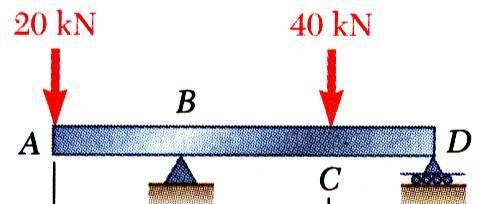
6 Beams SFD and BMD: Example () Draw the shear and bending moment diagrams for the beam and loading shown. Solution: Draw FBD and find out the support reactions using equilibrium equations 6

 M C = +8 knm V 5 = -14 kn; M 5 = -0x+46 (x-.")
7 SFD and BMD: Example () Use equilibrium conditions at all sections to get the unknown SF and BM F y 0 : 0kN V1 0 V1 0kN M1 0 : 0kN0m M1 0 M 1 0 V = -0 kn; M = -0x knm V 3 = +6 kn; M 3 = -0x+46 0 = -0x M B = -50 knm V 4 = +6 kn; M 4 = -0x+46 (x-.5) M C = +8 knm V 5 = -14 kn; M 5 = -0x+46 (x-.5)-40 0 M C = +8 knm V 6 = -14 kn; M 6 = -0x+46 (x-.5)-40 (x-5.5) M D = 0 knm 7

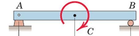
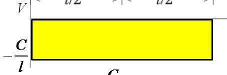
8 Beams SFD and BMD: Example (3) Draw the SFD and BMD for the beam acted upon by a clockwise couple at mid point Solution: Draw FBD of the beam and Calculate the support reactions C l V C C l Draw the SFD and the BMD starting From any one end C l M C C 8

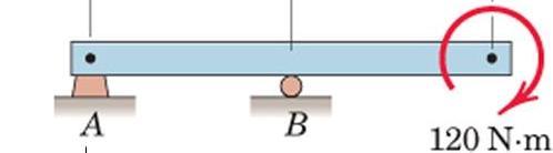
9 Beams SFD and BMD: Example (3) Draw the SFD and BMD for the beam Solution: Draw FBD of the beam and Calculate the support reactions M A = 0 R A = 60 N M B = 0 R B = 60 N 60 N V 60 N 10 Nm Draw the SFD and the BMD starting from any one end -60 N M -10 Nm 9
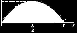
10 Beams SFD and BMD: Example (4) Draw the SFD and BMD for the beam Solution: Draw FBD of the entire beam and calculate support reactions using equilibrium equations w Reactions at supports: R A R B wl Develop the relations between loading, shear force, and bending moment and plot the SFD and BMD 10

11 Beams SFD and BMD: Example (4) Shear Force at any section: w V wl wx w Alternatively, V V BM at any section: Alternatively, M M V V 0 A A M L x x A x 0 wx wl M x 0 L w xdx wdx wx Vdx wl L wx w x x wx w w Lx x x Lx x M max wl dm M at V 0 8 dx 11


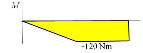
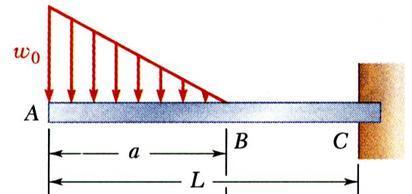
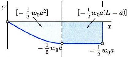
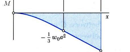
12 Beams SFD and BMD: Example (5) Draw the SFD and BMD for the Beam Area under SFD Solution: SFD and BMD can be plotted without determining support reactions since it is a cantilever beam. However, values of SF and BM can be verified at the support if support reactions are known. w0a w0a a w0a RC ; M C L 3L a 3 6 M 1


13 Beams SFD and BMD: Summary.5 m 3 m m SFD BMD m m w l/ l/ L SFD BMD 13


14 Beams Internal Effects Example: Find the internal torques at points B and C of the circular shaft subjected to three concentrated torques Solution: FBD of entire shaft Sections at B and C and FBDs of shaft segments AB and CD 14


15 Cables Flexible and Inextensible Cables Important Design Parameters Tension Span Sag Length 15


16 Cables Relations involving Tension, Span, Sag, and Length are reqd Obtained by examining the cable as a body in equilibrium It is assumed that any resistance offered to bending is negligible Force in cable is always along the direction of the cable. Flexible cables may be subjected to concentrated loads or distributed loads 16
17 Cables In some cases, weight of the cable is negligible compared with the loads it supports. In other cases, weight of the cable may be significant or may be the only load acting weight cannot be neglected. Three primary cases of analysis: Cables subjected to 1. concentrated load,. distributed load, 3. self weight Requirements for equilibrium are formulated in identical way provided Loading is coplanar with the cable 17
18 Cables Primary Assumption in Analysis: The cable is perfectly Flexible and Inextensible Flexible cable offers no resistance to bending tensile force acting in the cable is always tangent to the cable at points along its length Inextensible cable has a constant length both before and after the load is applied once the load is applied, geometry of the cable remains fixed cable or a segment of it can be treated as a rigid body 18
19 Cables General Relationships Equilibrium of the element: Simplifying using trigonometric expansions and dropping second order terms Further simplifying: Finally: where Equilibrium Equation Differential Equation for the Flexible Cable -Defines the shape of the cable -Can be used to solve two limiting cases of cable loading 19
20 Cables: Parabolic Cable Parabolic Cable Intensity of vertical loading is constant It can be proved that the cable hangs in a Parabolic Arc Differential Equation can be used to analyse 0
21 Cables: Catenary Cable Catenary Cable Hanging under the action of its own weight It can be proved that the cable hangs in a curved shape called Catenary Differential Equation can be used to analyse μ is the self weight per unit length 1
Beams. Beams are structural members that offer resistance to bending due to applied load
 Beams Beams are structural members that offer resistance to bending due to applied load 1 Beams Long prismatic members Non-prismatic sections also possible Each cross-section dimension Length of member
Types of Structures & Loads
 Structure Analysis I Chapter 4 1 Types of Structures & Loads 1Chapter Chapter 4 Internal lloading Developed in Structural Members Internal loading at a specified Point In General The loading for coplanar
Beams are bars of material that support. Beams are common structural members. Beams can support both concentrated and distributed loads
 Outline: Review External Effects on Beams Beams Internal Effects Sign Convention Shear Force and Bending Moment Diagrams (text method) Relationships between Loading, Shear Force and Bending Moments (faster
BEAM A horizontal or inclined structural member that is designed to resist forces acting to its axis is called a beam
 BEM horizontal or inclined structural member that is designed to resist forces acting to its axis is called a beam INTERNL FORCES IN BEM Whether or not a beam will break, depend on the internal resistances
Chapter 7: Internal Forces
 Chapter 7: Internal Forces Chapter Objectives To show how to use the method of sections for determining the internal loadings in a member. To generalize this procedure by formulating equations that can
Unit II Shear and Bending in Beams
 Unit II Shear and Bending in Beams Syllabus: Beams and Bending- Types of loads, supports - Shear Force and Bending Moment Diagrams for statically determinate beam with concentrated load, UDL, uniformly
Stress Analysis Lecture 4 ME 276 Spring Dr./ Ahmed Mohamed Nagib Elmekawy
 Stress Analysis Lecture 4 ME 76 Spring 017-018 Dr./ Ahmed Mohamed Nagib Elmekawy Shear and Moment Diagrams Beam Sign Convention The positive directions are as follows: The internal shear force causes a
2. Determine the deflection at C of the beam given in fig below. Use principal of virtual work. W L/2 B A L C
 CE-1259, Strength of Materials UNIT I STRESS, STRAIN DEFORMATION OF SOLIDS Part -A 1. Define strain energy density. 2. State Maxwell s reciprocal theorem. 3. Define proof resilience. 4. State Castigliano
Chapter Objectives. Copyright 2011 Pearson Education South Asia Pte Ltd
 Chapter Objectives To generalize the procedure by formulating equations that can be plotted so that they describe the internal shear and moment throughout a member. To use the relations between distributed
ENR202 Mechanics of Materials Lecture 4A Notes and Slides
 Slide 1 Copyright Notice Do not remove this notice. COMMMONWEALTH OF AUSTRALIA Copyright Regulations 1969 WARNING This material has been produced and communicated to you by or on behalf of the University
Three torques act on the shaft. Determine the internal torque at points A, B, C, and D.
 ... 7. Three torques act on the shaft. Determine the internal torque at points,, C, and D. Given: M 1 M M 3 300 Nm 400 Nm 00 Nm Solution: Section : x = 0; T M 1 M M 3 0 T M 1 M M 3 T 100.00 Nm Section
 techie-touch.blogspot.com DEPARTMENT OF CIVIL ENGINEERING ANNA UNIVERSITY QUESTION BANK CE 2302 STRUCTURAL ANALYSIS-I TWO MARK QUESTIONS UNIT I DEFLECTION OF DETERMINATE STRUCTURES 1. Write any two important
Shear Force V: Positive shear tends to rotate the segment clockwise.
 INTERNL FORCES IN EM efore a structural element can be designed, it is necessary to determine the internal forces that act within the element. The internal forces for a beam section will consist of a shear
Chapter 7: Bending and Shear in Simple Beams
 Chapter 7: Bending and Shear in Simple Beams Introduction A beam is a long, slender structural member that resists loads that are generally applied transverse (perpendicular) to its longitudinal axis.
Chapter 7 FORCES IN BEAMS AND CABLES
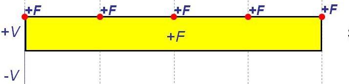
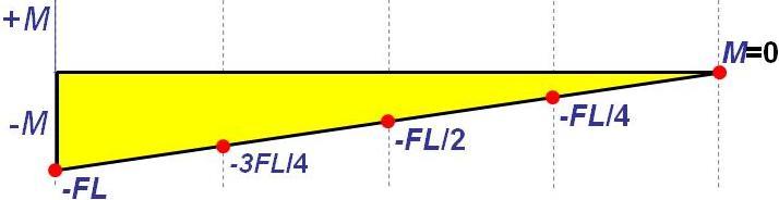
 hapter 7 FORES IN BEAMS AN ABLES onsider a straight two-force member AB subjected at A and B to equal and opposite forces F and -F directed along AB. utting the member AB at and drawing the free-body B
MAHALAKSHMI ENGINEERING COLLEGE
 CE840-STRENGTH OF TERIS - II PGE 1 HKSHI ENGINEERING COEGE TIRUCHIRPI - 611. QUESTION WITH NSWERS DEPRTENT : CIVI SEESTER: IV SU.CODE/ NE: CE 840 / Strength of aterials -II UNIT INDETERINTE ES 1. Define
UNIT-V MOMENT DISTRIBUTION METHOD
 UNIT-V MOMENT DISTRIBUTION METHOD Distribution and carryover of moments Stiffness and carry over factors Analysis of continuous beams Plane rigid frames with and without sway Neylor s simplification. Hardy
PURE BENDING. If a simply supported beam carries two point loads of 10 kn as shown in the following figure, pure bending occurs at segment BC.
 BENDING STRESS The effect of a bending moment applied to a cross-section of a beam is to induce a state of stress across that section. These stresses are known as bending stresses and they act normally
CHAPTER 8 BENDING MOMENT AND SHEAR FORCE DIAGRAMS
 CHPTE 8 BENDING MOMENT ND SHE FOCE DIGMS EXECISE 5, Page. Determine expressions for the bending moment and shearing force distributions for the following simply supported beam; hence, or otherwise, plot
Engineering Mechanics
 Engineering Mechanics Continued (5) Mohammed Ameen, Ph.D Professor of Civil Engineering B Section Forces in Beams Beams are thin prismatic members that are loaded transversely. Shear Force, Aial Force
MECHANICS OF MATERIALS. Analysis of Beams for Bending
 MECHANICS OF MATERIALS Analysis of Beams for Bending By NUR FARHAYU ARIFFIN Faculty of Civil Engineering & Earth Resources Chapter Description Expected Outcomes Define the elastic deformation of an axially
Laith Batarseh. internal forces
 Next Previous 1/8/2016 Chapter seven Laith Batarseh Home End Definitions When a member is subjected to external load, an and/or moment are generated inside this member. The value of the generated internal
Procedure for drawing shear force and bending moment diagram:
 Procedure for drawing shear force and bending moment diagram: Preamble: The advantage of plotting a variation of shear force F and bending moment M in a beam as a function of x' measured from one end of
[8] Bending and Shear Loading of Beams
![[8] Bending and Shear Loading of Beams](/thumbs/92/110949676.jpg "[8] Bending and Shear Loading of Beams") [8] Bending and Shear Loading of Beams Page 1 of 28 [8] Bending and Shear Loading of Beams [8.1] Bending of Beams (will not be covered in class) [8.2] Bending Strain and Stress [8.3] Shear in Straight
[8] Bending and Shear Loading of Beams Page 1 of 28 [8] Bending and Shear Loading of Beams [8.1] Bending of Beams (will not be covered in class) [8.2] Bending Strain and Stress [8.3] Shear in Straight
Module 2. Analysis of Statically Indeterminate Structures by the Matrix Force Method
 Module 2 Analysis of Statically Indeterminate Structures by the Matrix Force Method Lesson 8 The Force Method of Analysis: Beams Instructional Objectives After reading this chapter the student will be
MECE 3321: Mechanics of Solids Chapter 6
 MECE 3321: Mechanics of Solids Chapter 6 Samantha Ramirez Beams Beams are long straight members that carry loads perpendicular to their longitudinal axis Beams are classified by the way they are supported
SSC-JE MAINS ONLINE TEST SERIES / CIVIL ENGINEERING SOM + TOS
 SSC-JE MAINS ONLINE TEST SERIES / CIVIL ENGINEERING SOM + TOS Time Allowed:2 Hours Maximum Marks: 300 Attention: 1. Paper consists of Part A (Civil & Structural) Part B (Electrical) and Part C (Mechanical)
Chapter 2. Shear Force and Bending Moment. After successfully completing this chapter the students should be able to:
 Chapter Shear Force and Bending Moment This chapter begins with a discussion of beam types. It is also important for students to know and understand the reaction from the types of supports holding the
- Beams are structural member supporting lateral loadings, i.e., these applied perpendicular to the axes.
 4. Shear and Moment functions - Beams are structural member supporting lateral loadings, i.e., these applied perpendicular to the aes. - The design of such members requires a detailed knowledge of the
8.3 Shear and Bending-Moment Diagrams Constructed by Areas
 8.3 Shear and ending-moment Diagrams Constructed by reas 8.3 Shear and ending-moment Diagrams Constructed by reas Procedures and Strategies, page 1 of 3 Procedures and Strategies for Solving Problems Involving
8-5 Conjugate-Beam method. 8-5 Conjugate-Beam method. 8-5 Conjugate-Beam method. 8-5 Conjugate-Beam method
 The basis for the method comes from the similarity of eqn.1 &. to eqn 8. & 8. To show this similarity, we can write these eqn as shown dv dx w d θ M dx d M w dx d v M dx Here the shear V compares with
Shear Force and Bending Moment Diagrams for a Beam Steven Vukazich San Jose State University
 Shear Force and Bending oment Diagrams for a Beam Steven ukazich San Jose State University General procedure for the construction of internal force diagrams 1. Find all of the eternal forces and draw the
Assumptions: beam is initially straight, is elastically deformed by the loads, such that the slope and deflection of the elastic curve are
 *12.4 SLOPE & DISPLACEMENT BY THE MOMENT-AREA METHOD Assumptions: beam is initially straight, is elastically deformed by the loads, such that the slope and deflection of the elastic curve are very small,
Mechanics of Structure
 S.Y. Diploma : Sem. III [CE/CS/CR/CV] Mechanics of Structure Time: Hrs.] Prelim Question Paper Solution [Marks : 70 Q.1(a) Attempt any SIX of the following. [1] Q.1(a) Define moment of Inertia. State MI
Chapter 4.1: Shear and Moment Diagram
 Chapter 4.1: Shear and Moment Diagram Chapter 5: Stresses in Beams Chapter 6: Classical Methods Beam Types Generally, beams are classified according to how the beam is supported and according to crosssection
CHAPTER 4. Stresses in Beams
 CHAPTER 4 Stresses in Beams Problem 1. A rolled steel joint (RSJ) of -section has top and bottom flanges 150 mm 5 mm and web of size 00 mm 1 mm. t is used as a simply supported beam over a span of 4 m
6. Bending CHAPTER OBJECTIVES
 CHAPTER OBJECTIVES Determine stress in members caused by bending Discuss how to establish shear and moment diagrams for a beam or shaft Determine largest shear and moment in a member, and specify where
Determinate portal frame
 eterminate portal frame onsider the frame shown in the figure below with the aim of calculating the bending moment diagram (M), shear force diagram (SF), and axial force diagram (F). P H y R x x R y L
CHAPTER -6- BENDING Part -1-
 Ishik University / Sulaimani Civil Engineering Department Mechanics of Materials CE 211 CHAPTER -6- BENDING Part -1-1 CHAPTER -6- Bending Outlines of this chapter: 6.1. Chapter Objectives 6.2. Shear and
MAHALAKSHMI ENGINEERING COLLEGE
 AHAAKSHI ENGINEERING COEGE TIRUCHIRAPAI - 611. QUESTION WITH ANSWERS DEPARTENT : CIVI SEESTER: V SU.CODE/ NAE: CE 5 / Strength of aterials UNIT INDETERINATE EAS 1. Define statically indeterminate beams.
ENG202 Statics Lecture 16, Section 7.1
 ENG202 Statics Lecture 16, Section 7.1 Internal Forces Developed in Structural Members - Design of any structural member requires an investigation of the loading acting within the member in order to be
Bending Stress. Sign convention. Centroid of an area
 Bending Stress Sign convention The positive shear force and bending moments are as shown in the figure. Centroid of an area Figure 40: Sign convention followed. If the area can be divided into n parts
UNIT-I STRESS, STRAIN. 1. A Member A B C D is subjected to loading as shown in fig determine the total elongation. Take E= 2 x10 5 N/mm 2
 UNIT-I STRESS, STRAIN 1. A Member A B C D is subjected to loading as shown in fig determine the total elongation. Take E= 2 x10 5 N/mm 2 Young s modulus E= 2 x10 5 N/mm 2 Area1=900mm 2 Area2=400mm 2 Area3=625mm
CE6306 STRENGTH OF MATERIALS TWO MARK QUESTIONS WITH ANSWERS ACADEMIC YEAR
 CE6306 STRENGTH OF MATERIALS TWO MARK QUESTIONS WITH ANSWERS ACADEMIC YEAR 2014-2015 UNIT - 1 STRESS, STRAIN AND DEFORMATION OF SOLIDS PART- A 1. Define tensile stress and tensile strain. The stress induced
2 marks Questions and Answers
 1. Define the term strain energy. A: Strain Energy of the elastic body is defined as the internal work done by the external load in deforming or straining the body. 2. Define the terms: Resilience and
structural analysis Excessive beam deflection can be seen as a mode of failure.
 Structure Analysis I Chapter 8 Deflections Introduction Calculation of deflections is an important part of structural analysis Excessive beam deflection can be seen as a mode of failure. Extensive glass
Shear Force and Bending Moment Diagrams
 Shear Force and Bending Moment Diagrams V [ N ] x[m] M [ Nm] x[m] Competencies 1. Draw shear force and bending moment diagrams for point loads and distributed loads 2. Recognize the position of maximum
R13. II B. Tech I Semester Regular Examinations, Jan MECHANICS OF SOLIDS (Com. to ME, AME, AE, MTE) PART-A
 PART-A") SET - 1 II B. Tech I Semester Regular Examinations, Jan - 2015 MECHANICS OF SOLIDS (Com. to ME, AME, AE, MTE) Time: 3 hours Max. Marks: 70 Note: 1. Question Paper consists of two parts (Part-A and Part-B)
SET - 1 II B. Tech I Semester Regular Examinations, Jan - 2015 MECHANICS OF SOLIDS (Com. to ME, AME, AE, MTE) Time: 3 hours Max. Marks: 70 Note: 1. Question Paper consists of two parts (Part-A and Part-B)
Internal Internal Forces Forces
 Internal Forces ENGR 221 March 19, 2003 Lecture Goals Internal Force in Structures Shear Forces Bending Moment Shear and Bending moment Diagrams Internal Forces and Bending The bending moment, M. Moment
Mechanics of Materials
 Mechanics of Materials 2. Introduction Dr. Rami Zakaria References: 1. Engineering Mechanics: Statics, R.C. Hibbeler, 12 th ed, Pearson 2. Mechanics of Materials: R.C. Hibbeler, 9 th ed, Pearson 3. Mechanics
ENGINEERING MECHANICS SOLUTIONS UNIT-I
 LONG QUESTIONS ENGINEERING MECHANICS SOLUTIONS UNIT-I 1. A roller shown in Figure 1 is mass 150 Kg. What force P is necessary to start the roller over the block A? =90+25 =115 = 90+25.377 = 115.377 = 360-(115+115.377)
STRESS STRAIN AND DEFORMATION OF SOLIDS, STATES OF STRESS
 1 UNIT I STRESS STRAIN AND DEFORMATION OF SOLIDS, STATES OF STRESS 1. Define: Stress When an external force acts on a body, it undergoes deformation. At the same time the body resists deformation. The
BEAM DEFLECTION THE ELASTIC CURVE
 BEAM DEFLECTION Samantha Ramirez THE ELASTIC CURVE The deflection diagram of the longitudinal axis that passes through the centroid of each cross-sectional area of a beam. Supports that apply a moment
QUESTION BANK DEPARTMENT: CIVIL SEMESTER: III SUBJECT CODE: CE2201 SUBJECT NAME: MECHANICS OF SOLIDS UNIT 1- STRESS AND STRAIN PART A
 DEPARTMENT: CIVIL SUBJECT CODE: CE2201 QUESTION BANK SEMESTER: III SUBJECT NAME: MECHANICS OF SOLIDS UNIT 1- STRESS AND STRAIN PART A (2 Marks) 1. Define longitudinal strain and lateral strain. 2. State
QUESTION BANK SEMESTER: III SUBJECT NAME: MECHANICS OF SOLIDS
 QUESTION BANK SEMESTER: III SUBJECT NAME: MECHANICS OF SOLIDS UNIT 1- STRESS AND STRAIN PART A (2 Marks) 1. Define longitudinal strain and lateral strain. 2. State Hooke s law. 3. Define modular ratio,
STRENGTH OF MATERIALS-I. Unit-1. Simple stresses and strains
 STRENGTH OF MATERIALS-I Unit-1 Simple stresses and strains 1. What is the Principle of surveying 2. Define Magnetic, True & Arbitrary Meridians. 3. Mention different types of chains 4. Differentiate between
ENGINEERING COUNCIL DIPLOMA LEVEL MECHANICS OF SOLIDS D209 TUTORIAL 3 - SHEAR FORCE AND BENDING MOMENTS IN BEAMS
 ENGINEERING COUNCIL DIPLOMA LEVEL MECHANICS OF SOLIDS D209 TUTORIAL 3 - SHEAR FORCE AND BENDING MOMENTS IN BEAMS You should judge your progress by completing the self assessment exercises. On completion
 UNIT III DEFLECTION OF BEAMS 1. What are the methods for finding out the slope and deflection at a section? The important methods used for finding out the slope and deflection at a section in a loaded
FIXED BEAMS IN BENDING
 FIXED BEAMS IN BENDING INTRODUCTION Fixed or built-in beams are commonly used in building construction because they possess high rigidity in comparison to simply supported beams. When a simply supported
Mechanics of Materials II. Chapter III. A review of the fundamental formulation of stress, strain, and deflection
 Mechanics of Materials II Chapter III A review of the fundamental formulation of stress, strain, and deflection Outline Introduction Assumtions and limitations Axial loading Torsion of circular shafts
SAB2223 Mechanics of Materials and Structures
 S2223 Mechanics of Materials and Structures TOPIC 2 SHER FORCE ND ENDING MOMENT Lecturer: Dr. Shek Poi Ngian TOPIC 2 SHER FORCE ND ENDING MOMENT Shear Force and ending Moment Introduction Types of beams
Side Note (Needed for Deflection Calculations): Shear and Moment Diagrams Using Area Method
: Shear and Moment Diagrams Using Area Method") Side Note (Needed for Deflection Calculations): Shear and Moment Diagrams Using Area Method How do we draw the moment and shear diagram for an arbitrarily loaded beam? Is there a easier and faster way
Side Note (Needed for Deflection Calculations): Shear and Moment Diagrams Using Area Method How do we draw the moment and shear diagram for an arbitrarily loaded beam? Is there a easier and faster way
Module 3. Analysis of Statically Indeterminate Structures by the Displacement Method
 odule 3 Analysis of Statically Indeterminate Structures by the Displacement ethod Lesson 16 The Slope-Deflection ethod: rames Without Sidesway Instructional Objectives After reading this chapter the student
Engineering Mechanics Objective module 1 with solutions: A K GAIKAR
 Engineering Mechanics Objective module 1 with solutions: A K GAIKAR 1. What is the branch of engineering mechanics which refers to the study of stationary rigid body? A. Statics B. Kinetics C. Kinematics
Lecture 23 March 12, 2018 Chap 7.3
 Statics - TAM 210 & TAM 211 Lecture 23 March 12, 2018 Chap 7.3 Announcements Upcoming deadlines: Monday (3/12) Mastering Engineering Tutorial 9 Tuesday (3/13) PL HW 8 Quiz 5 (3/14-16) Sign up at CBTF Up
Chapter 8 Supplement: Deflection in Beams Double Integration Method
 Chapter 8 Supplement: Deflection in Beams Double Integration Method 8.5 Beam Deflection Double Integration Method In this supplement, we describe the methods for determining the equation of the deflection
five moments ELEMENTS OF ARCHITECTURAL STRUCTURES: FORM, BEHAVIOR, AND DESIGN DR. ANNE NICHOLS SPRING 2014 lecture ARCH 614
 ELEMENTS OF ARCHITECTURAL STRUCTURES: FORM, BEHAVIOR, AND DESIGN DR. ANNE NICHOLS SPRING 2014 lecture five moments Moments 1 Moments forces have the tendency to make a body rotate about an axis http://www.physics.umd.edu
Only for Reference Page 1 of 18
 Only for Reference www.civilpddc2013.weebly.com Page 1 of 18 Seat No.: Enrolment No. GUJARAT TECHNOLOGICAL UNIVERSITY PDDC - SEMESTER II EXAMINATION WINTER 2013 Subject Code: X20603 Date: 26-12-2013 Subject
UNIT I ENERGY PRINCIPLES
 UNIT I ENERGY PRINCIPLES Strain energy and strain energy density- strain energy in traction, shear in flexure and torsion- Castigliano s theorem Principle of virtual work application of energy theorems
OUTCOME 1 - TUTORIAL 3 BENDING MOMENTS. You should judge your progress by completing the self assessment exercises. CONTENTS
 Unit 2: Unit code: QCF Level: 4 Credit value: 15 Engineering Science L/601/1404 OUTCOME 1 - TUTORIAL 3 BENDING MOMENTS 1. Be able to determine the behavioural characteristics of elements of static engineering
Theory of Structures
 SAMPLE STUDY MATERIAL Postal Correspondence Course GATE, IES & PSUs Civil Engineering Theory of Structures C O N T E N T 1. ARCES... 3-14. ROLLING LOADS AND INFLUENCE LINES. 15-9 3. DETERMINACY AND INDETERMINACY..
CHAPTER OBJECTIVES Use various methods to determine the deflection and slope at specific pts on beams and shafts: 2. Discontinuity functions
 1. Deflections of Beams and Shafts CHAPTER OBJECTIVES Use various methods to determine the deflection and slope at specific pts on beams and shafts: 1. Integration method. Discontinuity functions 3. Method
5 Equilibrium of a Rigid Body Chapter Objectives
 5 Equilibrium of a Rigid Body Chapter Objectives Develop the equations of equilibrium for a rigid body Concept of the free-body diagram for a rigid body Solve rigid-body equilibrium problems using the
UNIT 1 STRESS STRAIN AND DEFORMATION OF SOLIDS, STATES OF STRESS 1. Define stress. When an external force acts on a body, it undergoes deformation.
 UNIT 1 STRESS STRAIN AND DEFORMATION OF SOLIDS, STATES OF STRESS 1. Define stress. When an external force acts on a body, it undergoes deformation. At the same time the body resists deformation. The magnitude
REVIEW FOR EXAM II. Dr. Ibrahim A. Assakkaf SPRING 2002
 REVIEW FOR EXM II. J. Clark School of Engineering Department of Civil and Environmental Engineering b Dr. Ibrahim. ssakkaf SPRING 00 ENES 0 Mechanics of Materials Department of Civil and Environmental
KINGS COLLEGE OF ENGINEERING DEPARTMENT OF MECHANICAL ENGINEERING QUESTION BANK. Subject code/name: ME2254/STRENGTH OF MATERIALS Year/Sem:II / IV
 KINGS COLLEGE OF ENGINEERING DEPARTMENT OF MECHANICAL ENGINEERING QUESTION BANK Subject code/name: ME2254/STRENGTH OF MATERIALS Year/Sem:II / IV UNIT I STRESS, STRAIN DEFORMATION OF SOLIDS PART A (2 MARKS)
Shear force and bending moment of beams 2.1 Beams 2.2 Classification of beams 1. Cantilever Beam Built-in encastre' Cantilever
 CHAPTER TWO Shear force and bending moment of beams 2.1 Beams A beam is a structural member resting on supports to carry vertical loads. Beams are generally placed horizontally; the amount and extent of
Sub. Code:
 Important Instructions to examiners: ) The answers should be examined by key words and not as word-to-word as given in the model answer scheme. ) The model answer and the answer written by candidate may
Symmetric Bending of Beams
 Symmetric Bending of Beams beam is any long structural member on which loads act perpendicular to the longitudinal axis. Learning objectives Understand the theory, its limitations and its applications
CIVIL DEPARTMENT MECHANICS OF STRUCTURES- ASSIGNMENT NO 1. Brach: CE YEAR:
 MECHANICS OF STRUCTURES- ASSIGNMENT NO 1 SEMESTER: V 1) Find the least moment of Inertia about the centroidal axes X-X and Y-Y of an unequal angle section 125 mm 75 mm 10 mm as shown in figure 2) Determine
CIV100 Mechanics. Module 5: Internal Forces and Design. by: Jinyue Zhang. By the end of this Module you should be able to:
 CIV100 Mechanics Module 5: Internal Forces and Design by: Jinyue Zhang Module Objective By the end of this Module you should be able to: Find internal forces of any structural members Understand how Shear
PERIYAR CENTENARY POLYTECHNIC COLLEGE PERIYAR NAGAR - VALLAM THANJAVUR. DEPARTMENT OF MECHANICAL ENGINEERING QUESTION BANK
 PERIYAR CENTENARY POLYTECHNIC COLLEGE PERIYAR NAGAR - VALLAM - 613 403 - THANJAVUR. DEPARTMENT OF MECHANICAL ENGINEERING QUESTION BANK Sub : Strength of Materials Year / Sem: II / III Sub Code : MEB 310
UNIT II 1. Sketch qualitatively the influence line for shear at D for the beam [M/J-15]
![UNIT II 1. Sketch qualitatively the influence line for shear at D for the beam [M/J-15]](/thumbs/95/124878500.jpg "UNIT II 1. Sketch qualitatively the influence line for shear at D for the beam [M/J-15]") UNIT II 1. Sketch qualitatively the influence line for shear at D for the beam [M/J-15] 2. Draw the influence line for shear to the left of B for the overhanging beam shown in Fig. Q. No. 4 [M/J-15] 3.
UNIT II 1. Sketch qualitatively the influence line for shear at D for the beam [M/J-15] 2. Draw the influence line for shear to the left of B for the overhanging beam shown in Fig. Q. No. 4 [M/J-15] 3.
CHAPTER The linear arch
 CHAPTER 6 The Romans were the first to use arches as major structural elements, employing them, mainly in semicircular form, in bridge and aqueduct construction and for roof supports, particularly the
Module 3. Analysis of Statically Indeterminate Structures by the Displacement Method
 odule 3 Analysis of Statically Indeterminate Structures by the Displacement ethod Lesson 14 The Slope-Deflection ethod: An Introduction Introduction As pointed out earlier, there are two distinct methods
Chapter 5 Equilibrium of a Rigid Body Objectives
 Chapter 5 Equilibrium of a Rigid Bod Objectives Develop the equations of equilibrium for a rigid bod Concept of the free-bod diagram for a rigid bod Solve rigid-bod equilibrium problems using the equations
FIXED BEAMS CONTINUOUS BEAMS
 FIXED BEAMS CONTINUOUS BEAMS INTRODUCTION A beam carried over more than two supports is known as a continuous beam. Railway bridges are common examples of continuous beams. But the beams in railway bridges
Tutorial #1 - CivE. 205 Name: I.D:
 Tutorial # - CivE. 0 Name: I.D: Eercise : For the Beam below: - Calculate the reactions at the supports and check the equilibrium of point a - Define the points at which there is change in load or beam
I certify that I have not given unauthorized aid nor have I received aid in the completion of this exam.
 NAME: ME 270 Fall 2012 Examination No. 3 - Makeup Please review the following statement: Group No.: I certify that I have not given unauthorized aid nor have I received aid in the completion of this exam.
Structural Analysis III The Moment Area Method Mohr s Theorems
 Structural Analysis III The Moment Area Method Mohr s Theorems 009/10 Dr. Colin Caprani 1 Contents 1. Introduction... 4 1.1 Purpose... 4. Theory... 6.1 asis... 6. Mohr s First Theorem (Mohr I)... 8.3 Mohr
UNIT IV FLEXIBILTY AND STIFFNESS METHOD
 SIDDHARTH GROUP OF INSTITUTIONS :: PUTTUR Siddharth Nagar, Narayanavanam Road 517583 QUESTION BANK (DESCRIPTIVE) Subject with Code : SA-II (13A01505) Year & Sem: III-B.Tech & I-Sem Course & Branch: B.Tech
QUESTION BANK. SEMESTER: V SUBJECT CODE / Name: CE 6501 / STRUCTURAL ANALYSIS-I
 QUESTION BANK DEPARTMENT: CIVIL SEMESTER: V SUBJECT CODE / Name: CE 6501 / STRUCTURAL ANALYSIS-I Unit 5 MOMENT DISTRIBUTION METHOD PART A (2 marks) 1. Differentiate between distribution factors and carry
3 Hours/100 Marks Seat No.
 *17304* 17304 14115 3 Hours/100 Marks Seat No. Instructions : (1) All questions are compulsory. (2) Illustrate your answers with neat sketches wherever necessary. (3) Figures to the right indicate full
When a rigid body is in equilibrium, both the resultant force and the resultant couple must be zero.
 When a rigid body is in equilibrium, both the resultant force and the resultant couple must be zero. 0 0 0 0 k M j M i M M k R j R i R F R z y x z y x Forces and moments acting on a rigid body could be
Continuous Beams - Flexibility Method
 ontinuous eams - Flexibility Method Qu. Sketch the M diagram for the beam shown in Fig.. Take E = 200kN/mm 2. 50kN 60kN-m = = 0kN/m D I = 60 50 40 x 0 6 mm 4 Fig. 60.0 23.5 D 25.7 6.9 M diagram in kn-m
SIGN CONVENTION OF STRESS RESULTANTS
 SIGN CONVENTION OF STRESS RESULTANTS A quick guide to understanding the sign conventions used in the ush Me ull Me models National HE STEM rogramme INTRODUCTION Representing stress resultants graphically
Sample Question Paper
 Scheme I Sample Question Paper Program Name : Mechanical Engineering Program Group Program Code : AE/ME/PG/PT/FG Semester : Third Course Title : Strength of Materials Marks : 70 Time: 3 Hrs. Instructions:
Engineering Mechanics Department of Mechanical Engineering Dr. G. Saravana Kumar Indian Institute of Technology, Guwahati
 Engineering Mechanics Department of Mechanical Engineering Dr. G. Saravana Kumar Indian Institute of Technology, Guwahati Module 3 Lecture 6 Internal Forces Today, we will see analysis of structures part
Solution: T, A1, A2, A3, L1, L2, L3, E1, E2, E3, P are known Five equations in five unknowns, F1, F2, F3, ua and va
 ME 323 Examination # 1 February 18, 2016 Name (Print) (Last) (First) Instructor PROBLEM #1 (20 points) A structure is constructed from members 1, 2 and 3, with these members made up of the same material
7.4 The Elementary Beam Theory
 7.4 The Elementary Beam Theory In this section, problems involving long and slender beams are addressed. s with pressure vessels, the geometry of the beam, and the specific type of loading which will be