CIV100 Mechanics. Module 5: Internal Forces and Design. by: Jinyue Zhang. By the end of this Module you should be able to:
|
|
|
- Gillian Jones
- 5 years ago
- Views:
Transcription
 and Bending Moment Diagrams (BMD) relate to the internal forces in structures Know how to draw SFD for beams Know how to draw BMD for beams Understand how different load")
1 CIV100 Mechanics Module 5: Internal Forces and Design by: Jinyue Zhang Module Objective By the end of this Module you should be able to: Find internal forces of any structural members Understand how Shear Force Diagrams (SFD) and Bending Moment Diagrams (BMD) relate to the internal forces in structures Know how to draw SFD for beams Know how to draw BMD for beams Understand how different load types (concentrated load, distributed load, couple) affect the shape of SFD and BMD Understand the design of structural members in tension Understand the design of structural members in bending 2010/10/26 1 1

2 Today s Objective Understand the concept of internal forces How to find internal forces of a structural member Understand the concept of SFD and BFD How to draw SFD and BFD of a beam with simple loading 2010/10/26 2 Internal Forces We have learnt this concept! 2010/10/26 3 2


3 Internal Forces Now let s look at multi-force member! Fx = 0 Fy = 0 Mo = /10/26 4 Internal Forces Naming those internal forces 2010/10/26 5 3
4 Finding Internal Forces Procedure for Analysis Solve the whole structure first, find all reaction forces if necessary. For frames and machines or their combinations, dismember the structure and obtain the reactions at each connection. Keep all distributed loadings, moments, and forces acting on the member in their exact location, then cut the member to analysis by an imaginary section at the point where the internal loading is to be determined. Draw FBD of the segment that has the least number of loads and apply EoE to find internal forces: Make assumption on unknown forces about their sense, if the EoE yields a negative scalar, your assumption was wrong. Moment should be summed at the cutting section where we eliminate the unknown normal and share forces. 2010/10/26 6 Example 1 The bar is fixed at its end and is loaded as shown. Determine the internal normal force at points B and C. 2010/10/26 7 4


5 Example 1 The bar is fixed at its end and is loaded as shown. Determine the internal normal force at points B and C. 2010/10/26 8 Example 2 Determine the internal normal force, shear force, and bending moment at point B. 2010/10/26 9 5

 Understand the sign convention of BM")
6 Example 2 Determine the internal normal force, shear force, and bending moment at point B. 2010/10/26 10 Today s Objective What is Bending Moment Diagram (BMD) What is Shear Force Diagram (SFD) Understand the sign convention of BM and SF 2 examples of plotting SFD and BMD 2010/10/


7 SFD and BMD An Interesting Applet! 2010/10/26 12 Sign Convention for Bending Moments In North America, if the moment tends to cause the beam to curve upward it is positive; if the moment tends to cause it to curve downward it is negative. If the upper side is in compression, it is positive. If it holds water, it is positive. If it smiles, it is positive. 2010/10/


8 Sign Convention for Shear Forces The only rule: if the shear force causes clockwise rotation of the member on which it acts, it a positive shear force. 2010/10/26 14 Example 1 Draw the shear and moment diagrams for the cantilevered beam. 2010/10/


9 Example 1 Draw the shear and moment diagrams for the cantilevered beam. Check you lecture notes to see how we develop the SFD and BMD. 2010/10/26 16 Example 2 Sketch the shear and moment diagrams for the beam. 2010/10/


10 Example 2 Sketch the shear and moment diagrams for the beam. Check you lecture notes to see how we develop the SFD and BMD. 2010/10/26 18 Today s Objective Understand the relation between loads and SFD/BMD Two examples 2010/10/


11 Loading, Shear Force, and Bending Moment The slop is equal to the shear force. The change of the shear ΔV between two points is equal to the negative of the area under the distributed loading curve between the points. (if downward is +) The change of the moment ΔM between two points is equal to the negative of the area under the shear diagram between the points. Points of zero shear represents points of Max/Min moment as dm/dx=0 2010/10/26 20 Loading, Shear Force, and Bending Moment Load V M 2010/10/
12 Example 1 Find internal forces at point C and then draw the shear and moment diagrams for the beam. 2010/10/26 22 Example 1 Find internal forces at point C and then draw the shear and moment diagrams for the beam. To solve the reactions at A and B M B =0 -(Ay)(6) + (8)(4.5) + (4.5)(2) + (6)(1.5) = 0 Ay = 9 kn M A =0 -(8)(1.5) - (4.5)(4) - (6)(4.5) +(By)(6) = 0 By = 9.5 kn Fx=0 Bx = 6 kn Check answers Fy= =0 To solve internal forces at C M C =0 Mc - (1.125)(0.5) - (3)(0.75) + (9.5)(1.5) = 0 Mc = kn.m M B =0 - (Cy)(1.5) + (1.125)(1) + (3)(0.75) = 0 Cy = kn.m Fx=0 Cx = 6 kn Check answers Fy= =0 2010/10/


13 Today s Objective Examples to review rules of drawing SFD and BMD Simple supported beam with uniformly distributed loading More complex examples 2010/10/26 24 Simply Supported Beam with UDL To Remember 1 M wl 2 Max = 8 The point where SF is zero means peak BM, because M/ x= /10/


14 Example 1 Draw SFD and BMD of the given beam. 2010/10/26 26 Example /10/
15 Example 2 Draw SFD, BMD, and NFD (normal force diagram) of the two members. 2010/10/26 28 Example 2 Draw SFD, BMD, and NFD (normal force diagram) of the two members. 2010/10/


16 Example 2 Draw SFD, BMD, and NFD (normal force diagram) of the two members /10/26 30 Today s Objective More examples on SFD and BMD 2010/10/

17 Example 1 A foundation beam supports four columns as shown. Knowing that the weight of each column has already been included in the load shown on the column, and the foundation beam has a weight of 30kN/m. Assuming the reaction of the ground is uniformly distributed, draw the SFD and BMD of the foundation beam. 2010/10/26 32 Example 1 A foundation beam supports four columns as shown. Knowing that the weight of each column has already been included in the load shown on the column, and the foundation beam has a weight of 30kN/m. Assuming the reaction of the ground is uniformly distributed, draw SFD/BMD of the foundation beam. 2010/10/
18 More Examples kN kN kN kN 2010/10/26 34 More Examples kN kN kN kN 2010/10/
19 Today s Objective Understand the following concepts Stress Strain Understand Hooke s Law The relationship between axial stress and axial strain Understand the stress-strain diagram The behaviour of ductile material The behaviour of brittle material Be able to design a structural member in tension Understand the concept of Load Factor (LF) 2010/10/26 36 Axial Stress Fcosɵ Fsinɵ ɵ F 2010/10/

 Axial stress = Force / Area")
 To Remember P σ = A 1N 1Pa = 2 1m 1N 1MPa")
20 Axial Stress Fcosɵ Fsinɵ ɵ F Axial Stress 2010/10/26 38 Axial Stress Caused by an axial force. Can be tensile stress or compressive stress. Symbol used σ (sigma) Axial stress = Force / Area σ=p/a Units are the same units of pressure (kpa, MPa, etc ) To Remember P σ = A 1N 1Pa = 2 1m 1N 1MPa = 2 1mm 2010/10/
21 Axial Stress This equation tells us that: The greater the applied force the greater the stress. The smaller the area on which the force is applied the greater the stress. To Remember P σ = A 1N 1Pa = 2 1m 1N 1MPa = 2 1mm 2010/10/26 40 Axial Strain Stresses cause the material to deform: Tension will cause elongation Compression will cause shrinkage Symbol used ε (epsilon) Axial Strain = Change in length / Original length ε = ΔL / L (no units) To Remember ΔL ε = L 2010/10/
22 Hooke s Law Robert Hooke s fundamental discovery (in 1676): for a spring, Axial Force Axial Deformation Mathematically it is A P ΔL P ΔL P ΔL σ ε σ = E ε L A L To Remember σ = E ε modulus of elasticity Young s modulus of elasticity Young s modulus Unit of Young s modulus: same as stress, Pa or MPa Relates axial stress to axial strain The modulus of elasticity is a property of material (each material has a different E ). The modulus of elasticity tells you how stiff a material is. The larger E means a stiffer material. 2010/10/26 42 Stress-Strain Curve: Ductile Material Typical ductile material in construction: low-carbon steel Hooke s Law is only good from point A to point B Slop of line AB is the Young s modulus In design practice, yield stress is a key parameter we frequently use We normally put a load factor to make it much safer 2010/10/
23 Stress-Strain Curve: Brittle Material Typical brittle material in construction: cast iron, concrete, rock Hooke s Law is only good at very beginning of the curve when the stress is small Suddenly rupture without plastic region (yielding stage) Capacity of resisting compression >>>>>>>>>>>> Capacity of resisting tension 2010/10/26 44 What is Design? Design is to select a system (or a part of a system like a structural member) to safely resist the anticipated loads. In order to do a design, you need to analyze a given structure: Understand the structure and its overall geometry Know the external loads Know the material used to build the structure Steps to design: Analyze the structure and find the internal forces Look at the available material and find its strength Select a solution to make sure the strength is greater than the load effects (the internal forces caused by external loads) There maybe many feasible solutions, you need to think other criteria like cost or aesthetics. 2010/10/
24 Load Factor To make a structure safe, we need: Maximum Load Stress < Yield Stress for the Material Is This Good Enough? Why? Loading might be greater then your estimate Material might not be as strong as specified Structure analysis might be an approximation or simplification Errors and mistakes To provide reasonable level of safety, we introduce a concept Load Factor The load factor (LF) enlarge the effect of the anticipated or service loads, and thus requires the structure to have greater capacity. For example, if a member will have a tensile stress of 10 MPa, after applying a LF of 1.7, we design the member as it would have a tensile stress of 10 MPa x 1.7 = 17 MPa 2010/10/26 46 Example 1 A Standard channel (C200x21) of 2m length is subject to a tension force of 500kN. Given that the modulus of elasticity for steel E= 200x10 3 MPa. Calculate the elongation in the steel member. 2010/10/
25 Example 1 A Standard channel (C200x21) of 2m length is subject to a tension force of 500kN. Given that the modulus of elasticity for steel E= 200x10 3 MPa. Calculate the elongation in the steel member. From tables: Cross Sectional Area = 2600mm 2 σ = (500 x 1000) / 2600 = MPa (or N/mm 2 ) ε = σ / E = / = x 10-4 L = L x ε = 2000 x x 10-4 = mm 2010/10/26 48 Example 2 Design member AC of the truss. Structural Steel is to be used in the design. The yield stress for the steel is 310 MPa, E=2x10 5 MPa, and the load factor is 2.0. The rectangular cross-section (a=3b) will be cut from plates whose thickness, b, is only available in 5 mm increments. 2010/10/
26 Example 2 Design member AC of the truss. Structural Steel is to be used in the design. The yield stress for the steel is 310 MPa, E=2x10 5 MPa, and the load factor is 2.0. The rectangular cross-section (a=3b) will be cut from plates whose thickness, b, is only available in 5 mm increments. 2010/10/26 50 Today s Objective No buckling, ignore buckling issue in complementary notes! The tensile strength (yielding stress due to tension) may be different to its compressive strength (yielding stress due to compression). When design against axial forces, use the right yielding stress to calculate. Understand the relationship Between load, pressure, and stress block Between stress block and internal bending moment Calculate internal BM according to a given stress block Examples 2010/10/
27 Axial Stress in Bars We have studied stress in a two force member which is in either tension or compression. σ = P A We call it stress block 2010/10/26 52 Load, Pressure, and Stress External Load vs. Pressure Internal Forces vs. Stress A distributed load acting over an area can be visualized as a volume: (a) The volume is equal to the magnitude of the equivalent single force, and (b) The line of action of the equivalent single force passes through the centroid off the volume. H/2 H 2010/10/
28 Calculating Equivalent Force 2010/10/26 54 Calculating Equivalent Force 2010/10/
29 Stress Block and Internal BM When we say there is a internal BM at a certain section of a beam, what does it mean? How can the section have a BM? Who provides the moment? 2010/10/26 56 Example The stress blocks due to the internal bending moment at Q on QA of the shown beam is given in figure (b). Determine: 1. The total compression force due to the bending moment. 2. The internal bending moment at Q. 3. The value of the concentrated load P. 2010/10/
30 Example The stress blocks due to the internal bending moment at Q on QA of the shown beam is given in figure (b). Determine: 1. The total compression force due to the bending moment. 2. The internal bending moment at Q. 3. The value of the concentrated load P. 2010/10/26 58 Today s Objective More examples on stress blocks 2010/10/

31 Example 1 This section is used to fabricate a simply supported steel beam. The stress distribution due to the bending moment M in a certain section is shown in the diagram. Determine the total tension force and compression force, as well as the bending moment M. 2010/10/26 60 Example 1 This section is used to fabricate a simply supported steel beam. The stress distribution due to the bending moment M in a certain section is shown in the diagram. Determine the total tension force and compression force, as well as the bending moment M. Step-1: Divide the stress distribution into 3 distinct shapes (2 triangles and one rectangle) as shown. Step-2: Find the values of the forces: F1= (1/2) (66.5)(2x9.5)=118848N = kN F2 = (102)(9.5)=182293N = kn F3 = (1/2)( )(9.5)(102)=13021N = kn The volume of the compression stress block is the total compress force which is F1 + F2 + F3 = 314 kn The total tension force is same as compression force because of the symmetry of the section. Step-3: Find the moment caused by these forces (note these forces are equal and opposite thus causing a couple): M = F1(2*44.33) + F2(2*71.25) +F3(2* ) = kn.mm = 38.4 kn.m 2010/10/
32 Example 2 The cross section of a reinforced concrete beam is shown below along with the assumed distribution of the compression stress due to a bending moment M (the beam is subject to bending moment only). Determine: (a) The value of the compression force acting on the cross section (b) The tension stress in the steel bars (c) The bending moment M 2010/10/26 62 Example 2 The cross section of a reinforced concrete beam is shown below along with the assumed distribution of the compression stress due to a bending moment M (the beam is subject to bending moment only). Determine: (a) The value of the compression force acting on the cross section (b) The tension stress in the steel bars (c) The bending moment M (a) The value of compression force is the volume of stress block measured 110mm from the top over the entire width of the beam. The volume is further divided into two components: one cube plus one wedge. For the cube: F1=(22MPa)(110mm)(250mm)=605kN For the wedge: F2=(30MPa-22MPa)(110mm)(0.5)(250mm)=110kN Total compression force is F1+F2=715kN (b) The tension force is equal to the compression force because the beam is subject to bending moment only, i.e. no normal force, so the total tension force is 715kN. The total area of the four reinforce bars A=4πr 2 =4(3.14)(15) 2 =2827mm 2 Tension stress σ=p/a=715000n/2827mm 2 =252 MPa (c) When we calculate the centroidal axis on the composite section, we ignore the impact of reinforce bars, i.e. we still trade the entire section is made by homogeneous material because the area of the steel bars is too small compared to the concrete area and thus is not significant. Then the centroidal axis is at the half height. M due to F1 = (605kN)(250mm-110mm/2)=117.98kNm M due to F2 = (110kN)(250mm-110mm/3)=23.467kNm 250mm 195mm 213mm M due to tension = (715kN)(250mm-50mm)=143kNm Total Moment = =284kNm 200mm 2010/10/
33 Today s Objective Understand the stress due to bending moment Three fundamental assumptions Bending stress formula, i.e. how to calculate bending stress Design a beam subject to bending moment 2010/10/26 64 Application We have leant How to calculate the bending moment of a section (the internal force) What is the bending stress How they are related In many circumstances we need To design a structural member (for example a beam) to hold the loads As such, we need Analyze the internal forces, i.e. draw SFD, BMD, and NFD Find the critical section Design against NF, BM, and SF: σ factored loads < σ yield 2010/10/


34 Three Fundamental Assumptions The material is linearly elastic, i.e. stress is proportional to strain. σ ε σ = E ε Plane sections before bending remain plane during bending. Bending stresses are independent of the stresses caused by internal axial and shear forces in the beam. 2010/10/26 66 Bending Stress Formula Let s look at a bending element isolated from a beam y z X σ = To Remember M I Z Z y σ ε ε y z σ y σ = K y M σ = I 2010/10/26 67 Z Z y 34
35 Design against Bending Moment Where is the maximum stress due to bending, if we can assume the beam is uniform (prismatic)? At the location of the maximum bending moment. This can be determined by checking BMD. At the location in the cross section where y is maximum, i.e. in the extreme top and bottom fibres. σ M LF yield I Section Modulus S Unit is mm 3 S I Z Z = y max max y max Z S σ = S To Remember M I Z Z I y Z Z = y max required M = σ max yield LF S required = I y Z max M = σ max yield LF 2010/10/26 68 Example /10/
36 Example /10/26 70 Example 2 The wooden beam has a cross section (a x 3a). The tensile strength of wood is 12MPa and compressive strength of wood is 15MPa. Using a LF of 2 to design the beam section. 2010/10/

37 Example 2 The wooden beam has a cross section (a x 3a, increments of a = 10mm). The tensile strength of wood is 12MPa and compressive strength of wood is 15MPa. Using a LF of 2 to design the beam section. 2010/10/26 72 Be Prepared Final Exam: Monday, Dec. 8, 2008, 9:30am Previous final papers fall term and solution: posted! Earlier exams and spring term exams are available at: then browse by code, select CIV, then CIV101 Quiz #2 and Tutorial #10 Quiz #2, this week, the first hour of tutorial class Office hour for Quiz #2: Wednesday GB224 Get them back on Wednesday, Dec. 3 rd, 3-5pm, out of GB224 Bring your questions about marking to the TA during office hours No resubmission for Tutorial #10, you will get 2 marks as long as your submit and complete Office hours before your final: Dec. 4-7, GB224 (i2c lab) Luai (Thursday, Dec. 4, who is marking your Quiz 2 and Tutorial 10) Ahmed (Saturday, Dec. 6) I will be available all 4 days 2010/10/
 30º 2010/10/26 76 (Neglect beam weight, don t check buckling) 30º 2010/10/26 77 39")
38 Example 1 For the shown beam, find the maximum bending moment. Select the least square section (a by a sq. mm) that can be used if the factor of safety is 1.3 and maximum stress is 280 MPa. (Neglect beam weight, don t check buckling, increments of a = 5mm) 30º 2010/10/26 76 Example 1 For the shown beam, find the maximum bending moment. Select the least square section (a by a sq. mm) that can be used if the factor of safety is 1.3 and maximum stress is 280 MPa. (Neglect beam weight, don t check buckling) 30º 2010/10/
39 Example 2 Choose a steel wideflange beam to take the shown loads. The yield stress is 290MPa and the load factor is 1.8. Neglecting the selfweight of the beam, and design criterion is to minimize weight. (a) Assuming no depth limits. (b) The depth is not to exceed 400mm 2010/10/26 78 Example /10/
40 Example 2 Choose a steel wide-flange beam to take the shown loads. The yield stress is 290MPa and the load factor is 1.8. Neglecting the self-weight of the beam, and design criterion is to minimize weight. (a) Assuming no depth limits. (b) The depth is not to exceed 400mm Step 1: Solving for reactions Taking moment about A, solve By=85.714kN Taking moment about B, solve Ay=54.286kN Step 2: Draw BMD 1 2 M = ( x + 2) 20( x )( x ) = 10x x M = 0 x = m x M = kN m Step 3: calculate section modulus S S 6 M maxlf (10 )(1.8) 6 required = = = (10 ) σ yield 290 Step 4: choose a section (a) W457x89 (b) W305x97 mm /10/26 80 More Examples 2010/10/
41 More Examples 2010/10/
Mechanics of Structure
 S.Y. Diploma : Sem. III [CE/CS/CR/CV] Mechanics of Structure Time: Hrs.] Prelim Question Paper Solution [Marks : 70 Q.1(a) Attempt any SIX of the following. [1] Q.1(a) Define moment of Inertia. State MI
PURE BENDING. If a simply supported beam carries two point loads of 10 kn as shown in the following figure, pure bending occurs at segment BC.
 BENDING STRESS The effect of a bending moment applied to a cross-section of a beam is to induce a state of stress across that section. These stresses are known as bending stresses and they act normally
PERIYAR CENTENARY POLYTECHNIC COLLEGE PERIYAR NAGAR - VALLAM THANJAVUR. DEPARTMENT OF MECHANICAL ENGINEERING QUESTION BANK
 PERIYAR CENTENARY POLYTECHNIC COLLEGE PERIYAR NAGAR - VALLAM - 613 403 - THANJAVUR. DEPARTMENT OF MECHANICAL ENGINEERING QUESTION BANK Sub : Strength of Materials Year / Sem: II / III Sub Code : MEB 310
CHAPTER 4. Stresses in Beams
 CHAPTER 4 Stresses in Beams Problem 1. A rolled steel joint (RSJ) of -section has top and bottom flanges 150 mm 5 mm and web of size 00 mm 1 mm. t is used as a simply supported beam over a span of 4 m
CIVIL DEPARTMENT MECHANICS OF STRUCTURES- ASSIGNMENT NO 1. Brach: CE YEAR:
 MECHANICS OF STRUCTURES- ASSIGNMENT NO 1 SEMESTER: V 1) Find the least moment of Inertia about the centroidal axes X-X and Y-Y of an unequal angle section 125 mm 75 mm 10 mm as shown in figure 2) Determine
Beams. Beams are structural members that offer resistance to bending due to applied load
 Beams Beams are structural members that offer resistance to bending due to applied load 1 Beams Long prismatic members Non-prismatic sections also possible Each cross-section dimension Length of member
UNIT-I STRESS, STRAIN. 1. A Member A B C D is subjected to loading as shown in fig determine the total elongation. Take E= 2 x10 5 N/mm 2
 UNIT-I STRESS, STRAIN 1. A Member A B C D is subjected to loading as shown in fig determine the total elongation. Take E= 2 x10 5 N/mm 2 Young s modulus E= 2 x10 5 N/mm 2 Area1=900mm 2 Area2=400mm 2 Area3=625mm
QUESTION BANK DEPARTMENT: CIVIL SEMESTER: III SUBJECT CODE: CE2201 SUBJECT NAME: MECHANICS OF SOLIDS UNIT 1- STRESS AND STRAIN PART A
 DEPARTMENT: CIVIL SUBJECT CODE: CE2201 QUESTION BANK SEMESTER: III SUBJECT NAME: MECHANICS OF SOLIDS UNIT 1- STRESS AND STRAIN PART A (2 Marks) 1. Define longitudinal strain and lateral strain. 2. State
NORMAL STRESS. The simplest form of stress is normal stress/direct stress, which is the stress perpendicular to the surface on which it acts.
 NORMAL STRESS The simplest form of stress is normal stress/direct stress, which is the stress perpendicular to the surface on which it acts. σ = force/area = P/A where σ = the normal stress P = the centric
QUESTION BANK SEMESTER: III SUBJECT NAME: MECHANICS OF SOLIDS
 QUESTION BANK SEMESTER: III SUBJECT NAME: MECHANICS OF SOLIDS UNIT 1- STRESS AND STRAIN PART A (2 Marks) 1. Define longitudinal strain and lateral strain. 2. State Hooke s law. 3. Define modular ratio,
[8] Bending and Shear Loading of Beams
![[8] Bending and Shear Loading of Beams](/thumbs/92/110949676.jpg "[8] Bending and Shear Loading of Beams") [8] Bending and Shear Loading of Beams Page 1 of 28 [8] Bending and Shear Loading of Beams [8.1] Bending of Beams (will not be covered in class) [8.2] Bending Strain and Stress [8.3] Shear in Straight
[8] Bending and Shear Loading of Beams Page 1 of 28 [8] Bending and Shear Loading of Beams [8.1] Bending of Beams (will not be covered in class) [8.2] Bending Strain and Stress [8.3] Shear in Straight
ENGINEERING COUNCIL DIPLOMA LEVEL MECHANICS OF SOLIDS D209 TUTORIAL 3 - SHEAR FORCE AND BENDING MOMENTS IN BEAMS
 ENGINEERING COUNCIL DIPLOMA LEVEL MECHANICS OF SOLIDS D209 TUTORIAL 3 - SHEAR FORCE AND BENDING MOMENTS IN BEAMS You should judge your progress by completing the self assessment exercises. On completion
ISHIK UNIVERSITY DEPARTMENT OF MECHATRONICS ENGINEERING
 ISHIK UNIVERSITY DEPARTMENT OF MECHATRONICS ENGINEERING QUESTION BANK FOR THE MECHANICS OF MATERIALS-I 1. A rod 150 cm long and of diameter 2.0 cm is subjected to an axial pull of 20 kn. If the modulus
OUTCOME 1 - TUTORIAL 3 BENDING MOMENTS. You should judge your progress by completing the self assessment exercises. CONTENTS
 Unit 2: Unit code: QCF Level: 4 Credit value: 15 Engineering Science L/601/1404 OUTCOME 1 - TUTORIAL 3 BENDING MOMENTS 1. Be able to determine the behavioural characteristics of elements of static engineering
UNIVERSITY OF BOLTON SCHOOL OF ENGINEERING. BEng (HONS) CIVIL ENGINEERING SEMESTER 1 EXAMINATION 2016/2017 MATHEMATICS & STRUCTURAL ANALYSIS
 CIVIL ENGINEERING SEMESTER 1 EXAMINATION 2016/2017 MATHEMATICS & STRUCTURAL ANALYSIS") TW21 UNIVERSITY OF BOLTON SCHOOL OF ENGINEERING BEng (HONS) CIVIL ENGINEERING SEMESTER 1 EXAMINATION 2016/2017 MATHEMATICS & STRUCTURAL ANALYSIS MODULE NO: CIE4011 Date: Wednesday 11 th January 2017 Time:
TW21 UNIVERSITY OF BOLTON SCHOOL OF ENGINEERING BEng (HONS) CIVIL ENGINEERING SEMESTER 1 EXAMINATION 2016/2017 MATHEMATICS & STRUCTURAL ANALYSIS MODULE NO: CIE4011 Date: Wednesday 11 th January 2017 Time:
 mportant nstructions to examiners: ) The answers should be examined by key words and not as word-to-word as given in the model answer scheme. ) The model answer and the answer written by candidate may
Sample Question Paper
 Scheme I Sample Question Paper Program Name : Mechanical Engineering Program Group Program Code : AE/ME/PG/PT/FG Semester : Third Course Title : Strength of Materials Marks : 70 Time: 3 Hrs. Instructions:
Stress Analysis Lecture 4 ME 276 Spring Dr./ Ahmed Mohamed Nagib Elmekawy
 Stress Analysis Lecture 4 ME 76 Spring 017-018 Dr./ Ahmed Mohamed Nagib Elmekawy Shear and Moment Diagrams Beam Sign Convention The positive directions are as follows: The internal shear force causes a
Name :. Roll No. :... Invigilator s Signature :.. CS/B.TECH (CE-NEW)/SEM-3/CE-301/ SOLID MECHANICS
/SEM-3/CE-301/ SOLID MECHANICS") Name :. Roll No. :..... Invigilator s Signature :.. 2011 SOLID MECHANICS Time Allotted : 3 Hours Full Marks : 70 The figures in the margin indicate full marks. Candidates are required to give their answers
Name :. Roll No. :..... Invigilator s Signature :.. 2011 SOLID MECHANICS Time Allotted : 3 Hours Full Marks : 70 The figures in the margin indicate full marks. Candidates are required to give their answers
STRENGTH OF MATERIALS-I. Unit-1. Simple stresses and strains
 STRENGTH OF MATERIALS-I Unit-1 Simple stresses and strains 1. What is the Principle of surveying 2. Define Magnetic, True & Arbitrary Meridians. 3. Mention different types of chains 4. Differentiate between
Chapter Objectives. Design a beam to resist both bendingand shear loads
 Chapter Objectives Design a beam to resist both bendingand shear loads A Bridge Deck under Bending Action Castellated Beams Post-tensioned Concrete Beam Lateral Distortion of a Beam Due to Lateral Load
FIXED BEAMS IN BENDING
 FIXED BEAMS IN BENDING INTRODUCTION Fixed or built-in beams are commonly used in building construction because they possess high rigidity in comparison to simply supported beams. When a simply supported
2. Determine the deflection at C of the beam given in fig below. Use principal of virtual work. W L/2 B A L C
 CE-1259, Strength of Materials UNIT I STRESS, STRAIN DEFORMATION OF SOLIDS Part -A 1. Define strain energy density. 2. State Maxwell s reciprocal theorem. 3. Define proof resilience. 4. State Castigliano
D : SOLID MECHANICS. Q. 1 Q. 9 carry one mark each. Q.1 Find the force (in kn) in the member BH of the truss shown.
 in the member BH of the truss shown.") D : SOLID MECHANICS Q. 1 Q. 9 carry one mark each. Q.1 Find the force (in kn) in the member BH of the truss shown. Q.2 Consider the forces of magnitude F acting on the sides of the regular hexagon having
D : SOLID MECHANICS Q. 1 Q. 9 carry one mark each. Q.1 Find the force (in kn) in the member BH of the truss shown. Q.2 Consider the forces of magnitude F acting on the sides of the regular hexagon having
MARKS DISTRIBUTION AS PER CHAPTER (QUESTION ASKED IN GTU EXAM) Name Of Chapter. Applications of. Friction. Centroid & Moment.
 Name Of Chapter. Applications of. Friction. Centroid & Moment.") Introduction Fundamentals of statics Applications of fundamentals of statics Friction Centroid & Moment of inertia Simple Stresses & Strain Stresses in Beam Torsion Principle Stresses DEPARTMENT OF CIVIL
Introduction Fundamentals of statics Applications of fundamentals of statics Friction Centroid & Moment of inertia Simple Stresses & Strain Stresses in Beam Torsion Principle Stresses DEPARTMENT OF CIVIL
BE Semester- I ( ) Question Bank (MECHANICS OF SOLIDS)
 Question Bank (MECHANICS OF SOLIDS)") BE Semester- I ( ) Question Bank (MECHANICS OF SOLIDS) All questions carry equal marks(10 marks) Q.1 (a) Write the SI units of following quantities and also mention whether it is scalar or vector: (i)
BE Semester- I ( ) Question Bank (MECHANICS OF SOLIDS) All questions carry equal marks(10 marks) Q.1 (a) Write the SI units of following quantities and also mention whether it is scalar or vector: (i)
CE6306 STRENGTH OF MATERIALS TWO MARK QUESTIONS WITH ANSWERS ACADEMIC YEAR
 CE6306 STRENGTH OF MATERIALS TWO MARK QUESTIONS WITH ANSWERS ACADEMIC YEAR 2014-2015 UNIT - 1 STRESS, STRAIN AND DEFORMATION OF SOLIDS PART- A 1. Define tensile stress and tensile strain. The stress induced
6. Bending CHAPTER OBJECTIVES
 CHAPTER OBJECTIVES Determine stress in members caused by bending Discuss how to establish shear and moment diagrams for a beam or shaft Determine largest shear and moment in a member, and specify where
COURSE TITLE : THEORY OF STRUCTURES -I COURSE CODE : 3013 COURSE CATEGORY : B PERIODS/WEEK : 6 PERIODS/SEMESTER: 90 CREDITS : 6
 COURSE TITLE : THEORY OF STRUCTURES -I COURSE CODE : 0 COURSE CATEGORY : B PERIODS/WEEK : 6 PERIODS/SEMESTER: 90 CREDITS : 6 TIME SCHEDULE Module Topics Period Moment of forces Support reactions Centre
18.Define the term modulus of resilience. May/June Define Principal Stress. 20. Define Hydrostatic Pressure.
 CE6306 STREGNTH OF MATERIALS Question Bank Unit-I STRESS, STRAIN, DEFORMATION OF SOLIDS PART-A 1. Define Poison s Ratio May/June 2009 2. What is thermal stress? May/June 2009 3. Estimate the load carried
DEPARTMENT OF CIVIL ENGINEERING
 KINGS COLLEGE OF ENGINEERING DEPARTMENT OF CIVIL ENGINEERING SUBJECT: CE 2252 STRENGTH OF MATERIALS UNIT: I ENERGY METHODS 1. Define: Strain Energy When an elastic body is under the action of external
Downloaded from Downloaded from / 1
 PURWANCHAL UNIVERSITY III SEMESTER FINAL EXAMINATION-2002 LEVEL : B. E. (Civil) SUBJECT: BEG256CI, Strength of Material Full Marks: 80 TIME: 03:00 hrs Pass marks: 32 Candidates are required to give their
Part 1 is to be completed without notes, beam tables or a calculator. DO NOT turn Part 2 over until you have completed and turned in Part 1.
 NAME CM 3505 Fall 06 Test 2 Part 1 is to be completed without notes, beam tables or a calculator. Part 2 is to be completed after turning in Part 1. DO NOT turn Part 2 over until you have completed and
2012 MECHANICS OF SOLIDS
 R10 SET - 1 II B.Tech II Semester, Regular Examinations, April 2012 MECHANICS OF SOLIDS (Com. to ME, AME, MM) Time: 3 hours Max. Marks: 75 Answer any FIVE Questions All Questions carry Equal Marks ~~~~~~~~~~~~~~~~~~~~~~
Types of Structures & Loads
 Structure Analysis I Chapter 4 1 Types of Structures & Loads 1Chapter Chapter 4 Internal lloading Developed in Structural Members Internal loading at a specified Point In General The loading for coplanar
3 Hours/100 Marks Seat No.
 *17304* 17304 14115 3 Hours/100 Marks Seat No. Instructions : (1) All questions are compulsory. (2) Illustrate your answers with neat sketches wherever necessary. (3) Figures to the right indicate full
INTRODUCTION (Cont..)
") INTRODUCTION Name : Mohamad Redhwan Abd Aziz Post : Lecturer @ DEAN CENTER OF HND STUDIES Subject : Solid Mechanics Code : BME 2033 Room : CENTER OF HND STUDIES OFFICE H/P No. : 019-2579663 W/SITE : Http://tatiuc.edu.my/redhwan
INTRODUCTION Name : Mohamad Redhwan Abd Aziz Post : Lecturer @ DEAN CENTER OF HND STUDIES Subject : Solid Mechanics Code : BME 2033 Room : CENTER OF HND STUDIES OFFICE H/P No. : 019-2579663 W/SITE : Http://tatiuc.edu.my/redhwan
Only for Reference Page 1 of 18
 Only for Reference www.civilpddc2013.weebly.com Page 1 of 18 Seat No.: Enrolment No. GUJARAT TECHNOLOGICAL UNIVERSITY PDDC - SEMESTER II EXAMINATION WINTER 2013 Subject Code: X20603 Date: 26-12-2013 Subject
ME 2570 MECHANICS OF MATERIALS
 ME 2570 MECHANICS OF MATERIALS Chapter III. Mechanical Properties of Materials 1 Tension and Compression Test The strength of a material depends on its ability to sustain a load without undue deformation
SRI CHANDRASEKHARENDRA SARASWATHI VISWA MAHAVIDHYALAYA
 SRI CHANDRASEKHARENDRA SARASWATHI VISWA MAHAVIDHYALAYA (Declared as Deemed-to-be University under Section 3 of the UGC Act, 1956, Vide notification No.F.9.9/92-U-3 dated 26 th May 1993 of the Govt. of
PDDC 1 st Semester Civil Engineering Department Assignments of Mechanics of Solids [ ] Introduction, Fundamentals of Statics
![PDDC 1 st Semester Civil Engineering Department Assignments of Mechanics of Solids [ ] Introduction, Fundamentals of Statics](/thumbs/92/109382806.jpg "PDDC 1 st Semester Civil Engineering Department Assignments of Mechanics of Solids [ ] Introduction, Fundamentals of Statics") Page1 PDDC 1 st Semester Civil Engineering Department Assignments of Mechanics of Solids [2910601] Introduction, Fundamentals of Statics 1. Differentiate between Scalar and Vector quantity. Write S.I.
Page1 PDDC 1 st Semester Civil Engineering Department Assignments of Mechanics of Solids [2910601] Introduction, Fundamentals of Statics 1. Differentiate between Scalar and Vector quantity. Write S.I.
KINGS COLLEGE OF ENGINEERING DEPARTMENT OF MECHANICAL ENGINEERING QUESTION BANK. Subject code/name: ME2254/STRENGTH OF MATERIALS Year/Sem:II / IV
 KINGS COLLEGE OF ENGINEERING DEPARTMENT OF MECHANICAL ENGINEERING QUESTION BANK Subject code/name: ME2254/STRENGTH OF MATERIALS Year/Sem:II / IV UNIT I STRESS, STRAIN DEFORMATION OF SOLIDS PART A (2 MARKS)
Mechanics of Materials II. Chapter III. A review of the fundamental formulation of stress, strain, and deflection
 Mechanics of Materials II Chapter III A review of the fundamental formulation of stress, strain, and deflection Outline Introduction Assumtions and limitations Axial loading Torsion of circular shafts
UNIT 1 STRESS STRAIN AND DEFORMATION OF SOLIDS, STATES OF STRESS 1. Define stress. When an external force acts on a body, it undergoes deformation.
 UNIT 1 STRESS STRAIN AND DEFORMATION OF SOLIDS, STATES OF STRESS 1. Define stress. When an external force acts on a body, it undergoes deformation. At the same time the body resists deformation. The magnitude
Engineering Science OUTCOME 1 - TUTORIAL 4 COLUMNS
 Unit 2: Unit code: QCF Level: Credit value: 15 Engineering Science L/601/10 OUTCOME 1 - TUTORIAL COLUMNS 1. Be able to determine the behavioural characteristics of elements of static engineering systems
Sub. Code:
 Important Instructions to examiners: ) The answers should be examined by key words and not as word-to-word as given in the model answer scheme. ) The model answer and the answer written by candidate may
Entrance exam Master Course
 - 1 - Guidelines for completion of test: On each page, fill in your name and your application code Each question has four answers while only one answer is correct. o Marked correct answer means 4 points
By Dr. Mohammed Ramidh
 Engineering Materials Design Lecture.6 the design of beams By Dr. Mohammed Ramidh 6.1 INTRODUCTION Finding the shear forces and bending moments is an essential step in the design of any beam. we usually
R13. II B. Tech I Semester Regular Examinations, Jan MECHANICS OF SOLIDS (Com. to ME, AME, AE, MTE) PART-A
 PART-A") SET - 1 II B. Tech I Semester Regular Examinations, Jan - 2015 MECHANICS OF SOLIDS (Com. to ME, AME, AE, MTE) Time: 3 hours Max. Marks: 70 Note: 1. Question Paper consists of two parts (Part-A and Part-B)
SET - 1 II B. Tech I Semester Regular Examinations, Jan - 2015 MECHANICS OF SOLIDS (Com. to ME, AME, AE, MTE) Time: 3 hours Max. Marks: 70 Note: 1. Question Paper consists of two parts (Part-A and Part-B)
Reg. No. : Question Paper Code : B.Arch. DEGREE EXAMINATION, APRIL/MAY Second Semester AR 6201 MECHANICS OF STRUCTURES I
 WK 4 Reg. No. : Question Paper Code : 71387 B.Arch. DEGREE EXAMINATION, APRIL/MAY 2017. Second Semester AR 6201 MECHANICS OF STRUCTURES I (Regulations 2013) Time : Three hours Maximum : 100 marks Answer
9.5 Compression Members
 9.5 Compression Members This section covers the following topics. Introduction Analysis Development of Interaction Diagram Effect of Prestressing Force 9.5.1 Introduction Prestressing is meaningful when
SN QUESTION YEAR MARK 1. State and prove the relationship between shearing stress and rate of change of bending moment at a section in a loaded beam.
 ALPHA COLLEGE OF ENGINEERING AND TECHNOLOGY DEPARTMENT OF MECHANICAL ENGINEERING MECHANICS OF SOLIDS (21000) ASSIGNMENT 1 SIMPLE STRESSES AND STRAINS SN QUESTION YEAR MARK 1 State and prove the relationship
Civil Engineering Design (1) Design of Reinforced Concrete Columns 2006/7
 Design of Reinforced Concrete Columns 2006/7") Civil Engineering Design (1) Design of Reinforced Concrete Columns 2006/7 Dr. Colin Caprani, Chartered Engineer 1 Contents 1. Introduction... 3 1.1 Background... 3 1.2 Failure Modes... 5 1.3 Design Aspects...
Civil Engineering Design (1) Design of Reinforced Concrete Columns 2006/7 Dr. Colin Caprani, Chartered Engineer 1 Contents 1. Introduction... 3 1.1 Background... 3 1.2 Failure Modes... 5 1.3 Design Aspects...
MECHANICS OF SOLIDS. (For B.E. Mechanical Engineering Students) As per New Revised Syllabus of APJ Abdul Kalam Technological University
 As per New Revised Syllabus of APJ Abdul Kalam Technological University") MECHANICS OF SOLIDS (For B.E. Mechanical Engineering Students) As per New Revised Syllabus of APJ Abdul Kalam Technological University Dr. S.Ramachandran, M.E., Ph.D., Mr. V.J. George, M.E., Mr. S. Kumaran,
MECHANICS OF SOLIDS (For B.E. Mechanical Engineering Students) As per New Revised Syllabus of APJ Abdul Kalam Technological University Dr. S.Ramachandran, M.E., Ph.D., Mr. V.J. George, M.E., Mr. S. Kumaran,
Mechanics of Materials CIVL 3322 / MECH 3322
 Mechanics of Materials CIVL 3322 / MECH 3322 2 3 4 5 6 7 8 9 10 A Quiz 11 A Quiz 12 A Quiz 13 A Quiz 14 A Quiz 15 A Quiz 16 In Statics, we spent most of our time looking at reactions at supports Two variations
71- Laxmi Nagar (South), Niwaru Road, Jhotwara, Jaipur ,India. Phone: Mob. : /
, Niwaru Road, Jhotwara, Jaipur ,India. Phone: Mob. : /") www.aarekh.com 71- Laxmi Nagar (South), Niwaru Road, Jhotwara, Jaipur 302 012,India. Phone: 0141-2348647 Mob. : +91-9799435640 / 9166936207 1. Limiting values of poisson s ratio are (a) -1 and 0.5 (b)
www.aarekh.com 71- Laxmi Nagar (South), Niwaru Road, Jhotwara, Jaipur 302 012,India. Phone: 0141-2348647 Mob. : +91-9799435640 / 9166936207 1. Limiting values of poisson s ratio are (a) -1 and 0.5 (b)
Strength of Materials (15CV 32)
") Strength of Materials (15CV 32) Module 1 : Simple Stresses and Strains Dr. H. Ananthan, Professor, VVIET,MYSURU 8/21/2017 Introduction, Definition and concept and of stress and strain. Hooke s law, Stress-Strain
Strength of Materials (15CV 32) Module 1 : Simple Stresses and Strains Dr. H. Ananthan, Professor, VVIET,MYSURU 8/21/2017 Introduction, Definition and concept and of stress and strain. Hooke s law, Stress-Strain
JUT!SI I I I TO BE RETURNED AT THE END OF EXAMINATION. THIS PAPER MUST NOT BE REMOVED FROM THE EXAM CENTRE. SURNAME: FIRST NAME: STUDENT NUMBER:
 JUT!SI I I I TO BE RETURNED AT THE END OF EXAMINATION. THIS PAPER MUST NOT BE REMOVED FROM THE EXAM CENTRE. SURNAME: FIRST NAME: STUDENT NUMBER: COURSE: Tutor's name: Tutorial class day & time: SPRING
Physics 8 Monday, November 20, 2017
 Physics 8 Monday, November 20, 2017 Pick up HW11 handout, due Dec 1 (Friday next week). This week, you re skimming/reading O/K ch8, which goes into more detail on beams. Since many people will be traveling
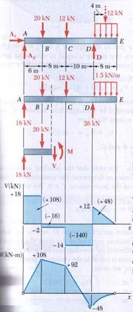
dv dx Slope of the shear diagram = - Value of applied loading dm dx Slope of the moment curve = Shear Force
 Beams SFD and BMD Shear and Moment Relationships w dv dx Slope of the shear diagram = - Value of applied loading V dm dx Slope of the moment curve = Shear Force Both equations not applicable at the point
DESIGN OF BEAMS AND SHAFTS
 DESIGN OF EAMS AND SHAFTS! asis for eam Design! Stress Variations Throughout a Prismatic eam! Design of pristmatic beams! Steel beams! Wooden beams! Design of Shaft! ombined bending! Torsion 1 asis for
ENG202 Statics Lecture 16, Section 7.1
 ENG202 Statics Lecture 16, Section 7.1 Internal Forces Developed in Structural Members - Design of any structural member requires an investigation of the loading acting within the member in order to be
FLOW CHART FOR DESIGN OF BEAMS
 FLOW CHART FOR DESIGN OF BEAMS Write Known Data Estimate self-weight of the member. a. The self-weight may be taken as 10 percent of the applied dead UDL or dead point load distributed over all the length.
Strength of Materials Prof. S.K.Bhattacharya Dept. of Civil Engineering, I.I.T., Kharagpur Lecture No.26 Stresses in Beams-I
 Strength of Materials Prof. S.K.Bhattacharya Dept. of Civil Engineering, I.I.T., Kharagpur Lecture No.26 Stresses in Beams-I Welcome to the first lesson of the 6th module which is on Stresses in Beams
five Mechanics of Materials 1 ARCHITECTURAL STRUCTURES: FORM, BEHAVIOR, AND DESIGN DR. ANNE NICHOLS SUMMER 2017 lecture
 ARCHITECTURAL STRUCTURES: FORM, BEHAVIOR, AND DESIGN DR. ANNE NICHOLS SUMMER 2017 lecture five mechanics www.carttalk.com of materials Mechanics of Materials 1 Mechanics of Materials MECHANICS MATERIALS
Physics 8 Monday, November 23, 2015
 Physics 8 Monday, November 23, 2015 Handing out HW11, due Friday, December 4. One or two more beam-related examples, then we ll move on to oscillations ( periodic motion ). This week s reading is Mazur
two structural analysis (statics & mechanics) APPLIED ACHITECTURAL STRUCTURES: DR. ANNE NICHOLS SPRING 2017 lecture STRUCTURAL ANALYSIS AND SYSTEMS
 APPLIED ACHITECTURAL STRUCTURES: DR. ANNE NICHOLS SPRING 2017 lecture STRUCTURAL ANALYSIS AND SYSTEMS") APPLIED ACHITECTURAL STRUCTURES: STRUCTURAL ANALYSIS AND SYSTEMS DR. ANNE NICHOLS SPRING 2017 lecture two structural analysis (statics & mechanics) Analysis 1 Structural Requirements strength serviceability
APPLIED ACHITECTURAL STRUCTURES: STRUCTURAL ANALYSIS AND SYSTEMS DR. ANNE NICHOLS SPRING 2017 lecture two structural analysis (statics & mechanics) Analysis 1 Structural Requirements strength serviceability
CIV100: Mechanics. Lecture Notes. Module 1: Force & Moment in 2D. You Know What to Do!
 CIV100: Mechanics Lecture Notes Module 1: Force & Moment in 2D By: Tamer El-Diraby, PhD, PEng. Associate Prof. & Director, I2C University of Toronto Acknowledgment: Hesham Osman, PhD and Jinyue Zhang,
National Exams May 2015
 National Exams May 2015 04-BS-6: Mechanics of Materials 3 hours duration Notes: If doubt exists as to the interpretation of any question, the candidate is urged to submit with the answer paper a clear
MECHANICS OF MATERIALS. Analysis of Beams for Bending
 MECHANICS OF MATERIALS Analysis of Beams for Bending By NUR FARHAYU ARIFFIN Faculty of Civil Engineering & Earth Resources Chapter Description Expected Outcomes Define the elastic deformation of an axially
Members Subjected to Torsional Loads
 Members Subjected to Torsional Loads Torsion of circular shafts Definition of Torsion: Consider a shaft rigidly clamped at one end and twisted at the other end by a torque T = F.d applied in a plane perpendicular
MECE 3321: Mechanics of Solids Chapter 6
 MECE 3321: Mechanics of Solids Chapter 6 Samantha Ramirez Beams Beams are long straight members that carry loads perpendicular to their longitudinal axis Beams are classified by the way they are supported
ME 202 STRENGTH OF MATERIALS SPRING 2014 HOMEWORK 4 SOLUTIONS
 ÇANKAYA UNIVERSITY MECHANICAL ENGINEERING DEPARTMENT ME 202 STRENGTH OF MATERIALS SPRING 2014 Due Date: 1 ST Lecture Hour of Week 12 (02 May 2014) Quiz Date: 3 rd Lecture Hour of Week 12 (08 May 2014)
Mechanics of Solids. Mechanics Of Solids. Suraj kr. Ray Department of Civil Engineering
 Mechanics Of Solids Suraj kr. Ray (surajjj2445@gmail.com) Department of Civil Engineering 1 Mechanics of Solids is a branch of applied mechanics that deals with the behaviour of solid bodies subjected
(Refer Slide Time: 01:00 01:01)
") Strength of Materials Prof: S.K.Bhattacharya Department of Civil Engineering Indian institute of Technology Kharagpur Lecture no 27 Lecture Title: Stresses in Beams- II Welcome to the second lesson of
Strength of Materials Prof: S.K.Bhattacharya Department of Civil Engineering Indian institute of Technology Kharagpur Lecture no 27 Lecture Title: Stresses in Beams- II Welcome to the second lesson of
Purpose of this Guide: To thoroughly prepare students for the exact types of problems that will be on Exam 3.
 ES230 STRENGTH OF MTERILS Exam 3 Study Guide Exam 3: Wednesday, March 8 th in-class Updated 3/3/17 Purpose of this Guide: To thoroughly prepare students for the exact types of problems that will be on
Solid Mechanics Chapter 1: Tension, Compression and Shear
 Solid Mechanics Chapter 1: Tension, Compression and Shear Dr. Imran Latif Department of Civil and Environmental Engineering College of Engineering University of Nizwa (UoN) 1 Why do we study Mechanics
Tutorial #1 - CivE. 205 Name: I.D:
 Tutorial # - CivE. 0 Name: I.D: Eercise : For the Beam below: - Calculate the reactions at the supports and check the equilibrium of point a - Define the points at which there is change in load or beam
Module 5: Theories of Failure
 Module 5: Theories of Failure Objectives: The objectives/outcomes of this lecture on Theories of Failure is to enable students for 1. Recognize loading on Structural Members/Machine elements and allowable
High Tech High Top Hat Technicians. An Introduction to Solid Mechanics. Is that supposed to bend there?
 High Tech High Top Hat Technicians An Introduction to Solid Mechanics Or Is that supposed to bend there? Why don't we fall through the floor? The power of any Spring is in the same proportion with the
There are three main types of structure - mass, framed and shells.
 STRUCTURES There are three main types of structure - mass, framed and shells. Mass structures perform due to their own weight. An example would be a dam. Frame structures resist loads due to the arrangement
Mechanics of Materials Primer
 Mechanics of Materials rimer Notation: A = area (net = with holes, bearing = in contact, etc...) b = total width of material at a horizontal section d = diameter of a hole D = symbol for diameter E = modulus
Laith Batarseh. internal forces
 Next Previous 1/8/2016 Chapter seven Laith Batarseh Home End Definitions When a member is subjected to external load, an and/or moment are generated inside this member. The value of the generated internal
Shear Force V: Positive shear tends to rotate the segment clockwise.
 INTERNL FORCES IN EM efore a structural element can be designed, it is necessary to determine the internal forces that act within the element. The internal forces for a beam section will consist of a shear
Level 7 Postgraduate Diploma in Engineering Computational mechanics using finite element method
 9210-203 Level 7 Postgraduate Diploma in Engineering Computational mechanics using finite element method You should have the following for this examination one answer book No additional data is attached
MECE 3321 MECHANICS OF SOLIDS CHAPTER 3
 MECE 3321 MECHANICS OF SOLIDS CHAPTER 3 Samantha Ramirez TENSION AND COMPRESSION TESTS Tension and compression tests are used primarily to determine the relationship between σ avg and ε avg in any material.
ENG2000 Chapter 7 Beams. ENG2000: R.I. Hornsey Beam: 1
 ENG2000 Chapter 7 Beams ENG2000: R.I. Hornsey Beam: 1 Overview In this chapter, we consider the stresses and moments present in loaded beams shear stress and bending moment diagrams We will also look at
 UNIT III DEFLECTION OF BEAMS 1. What are the methods for finding out the slope and deflection at a section? The important methods used for finding out the slope and deflection at a section in a loaded
Advanced Structural Analysis EGF Section Properties and Bending
 Advanced Structural Analysis EGF316 3. Section Properties and Bending 3.1 Loads in beams When we analyse beams, we need to consider various types of loads acting on them, for example, axial forces, shear
UNIT I SIMPLE STRESSES AND STRAINS
 Subject with Code : SM-1(15A01303) Year & Sem: II-B.Tech & I-Sem SIDDHARTH GROUP OF INSTITUTIONS :: PUTTUR Siddharth Nagar, Narayanavanam Road 517583 QUESTION BANK (DESCRIPTIVE) UNIT I SIMPLE STRESSES
Failure in Flexure. Introduction to Steel Design, Tensile Steel Members Modes of Failure & Effective Areas
 Introduction to Steel Design, Tensile Steel Members Modes of Failure & Effective Areas MORGAN STATE UNIVERSITY SCHOOL OF ARCHITECTURE AND PLANNING LECTURE VIII Dr. Jason E. Charalambides Failure in Flexure!
N = Shear stress / Shear strain
 UNIT - I 1. What is meant by factor of safety? [A/M-15] It is the ratio between ultimate stress to the working stress. Factor of safety = Ultimate stress Permissible stress 2. Define Resilience. [A/M-15]
BTECH MECHANICAL PRINCIPLES AND APPLICATIONS. Level 3 Unit 5
 BTECH MECHANICAL PRINCIPLES AND APPLICATIONS Level 3 Unit 5 FORCES AS VECTORS Vectors have a magnitude (amount) and a direction. Forces are vectors FORCES AS VECTORS (2 FORCES) Forces F1 and F2 are in
Symmetric Bending of Beams
 Symmetric Bending of Beams beam is any long structural member on which loads act perpendicular to the longitudinal axis. Learning objectives Understand the theory, its limitations and its applications
3.032 Problem Set 1 Fall 2007 Due: Start of Lecture,
 3.032 Problem Set 1 Fall 2007 Due: Start of Lecture, 09.14.07 1. The I35 bridge in Minneapolis collapsed in Summer 2007. The failure apparently occurred at a pin in the gusset plate of the truss supporting
Chapter. Materials. 1.1 Notations Used in This Chapter
 Chapter 1 Materials 1.1 Notations Used in This Chapter A Area of concrete cross-section C s Constant depending on the type of curing C t Creep coefficient (C t = ε sp /ε i ) C u Ultimate creep coefficient
Semester: BE 3 rd Subject :Mechanics of Solids ( ) Year: Faculty: Mr. Rohan S. Kariya. Tutorial 1
 Year: Faculty: Mr. Rohan S. Kariya. Tutorial 1") Semester: BE 3 rd Subject :Mechanics of Solids (2130003) Year: 2018-19 Faculty: Mr. Rohan S. Kariya Class: MA Tutorial 1 1 Define force and explain different type of force system with figures. 2 Explain
Semester: BE 3 rd Subject :Mechanics of Solids (2130003) Year: 2018-19 Faculty: Mr. Rohan S. Kariya Class: MA Tutorial 1 1 Define force and explain different type of force system with figures. 2 Explain
2 marks Questions and Answers
 1. Define the term strain energy. A: Strain Energy of the elastic body is defined as the internal work done by the external load in deforming or straining the body. 2. Define the terms: Resilience and
Chapter Two: Mechanical Properties of materials
 Chapter Two: Mechanical Properties of materials Time : 16 Hours An important consideration in the choice of a material is the way it behave when subjected to force. The mechanical properties of a material
CHAPTER 3 THE EFFECTS OF FORCES ON MATERIALS
 CHAPTER THE EFFECTS OF FORCES ON MATERIALS EXERCISE 1, Page 50 1. A rectangular bar having a cross-sectional area of 80 mm has a tensile force of 0 kn applied to it. Determine the stress in the bar. Stress