Chapter 5 Equilibrium of a Rigid Body Objectives
|
|
|
- Fay Neal
- 6 years ago
- Views:
Transcription
1 Chapter 5 Equilibrium of a Rigid Bod Objectives Develop the equations of equilibrium for a rigid bod Concept of the free-bod diagram for a rigid bod Solve rigid-bod equilibrium problems using the equations of equilibrium Chapter 5 Outline Conditions for Rigid Equilibrium Free-Bod Diagrams Equations of Equilibrium Two and Three-Force Members Free Bod Diagrams Equations of Equilibrium Constraints and Statical Determinac 43

2 5.1 Conditions for Rigid-Bod Equilibrium The equilibrium of a bod is epressed as F R M R O F 0 M O 0 Consider summing moments about some other point, such as point A, we require MA r FR MR O 0 44


3 5. Free Bod Diagrams Support Reactions If a support prevents the translation of a bod in a given direction, then a force is developed on the bod in that direction. If rotation is prevented, a couple moment is eerted on the bod. 45

4 5. Free Bod Diagrams 46


5 5. Free Bod Diagrams 47

6 5. Free Bod Diagram Weight and Center of Gravit Each particle has a specified weight Sstem can be represented b a single resultant force, known as weight W of the bod Location of the force application is known as the center of gravit 48


7 Eample 5.1 Draw the free-bod diagram of the uniform beam. The beam has a mass of 100kg. Solution Free-Bod Diagram Support at A is a fied wall Two forces acting on the beam at A denoted as A, A, with moment M A Unknown magnitudes of these vectors For uniform beam, Weight, W = 100(9.81) = 981N acting through beam s center of gravit, 3m from A 49

8 5.4 Two- and Three-Force Members Two-Force Members When forces are applied at onl two points on a member, the member is called a two-force member Onl force magnitude must be determined Three-Force Members When subjected to three forces, the forces are concurrent or parallel 50

9 5.5 3D Free-Bod Diagrams 51

10 5.5 Free-Bod Diagrams 5
11 5.7 Constraints for a Rigid Bod Redundant Constraints More support than needed for equilibrium Staticall indeterminate: more unknown loadings than equations of equilibrium 53
12 5.7 Constraints for a Rigid Bod Improper Constraints Instabilit caused b the improper constraining b the supports When all reactive forces are concurrent at this point, the bod is improperl constrained 54
13 Chapter 6 Structural Analsis Objectives Determine the forces in the members of a truss using the method of joints and the method of sections Analze forces acting on the members of frames and machines composed of pin-connected members Outline Simple Trusses The Method of Joints Zero-Force Members The Method of Sections Space Trusses Frames and Machines 55


14 6.1 Simple Truss A truss composed of slender members joined together at their end points Planar Trusses The analsis of the forces developed in the truss members is D Similar to roof truss, the bridge truss loading is also coplanar Assumptions for Design All loadings are applied at the joint - Weight of the members neglected The members are joined together b smooth pins - Assume connections provided the center lines of the joining members are concurrent 56
15 6.1 Simple Truss Simple Truss Form of a truss must be rigid to prevent collapse The simplest form that is rigid or stable is a triangle Method of Joints For truss, we need to know the force in each members Forces in the members are internal forces For eternal force members, equations of equilibrium can be applied Force sstem acting at each joint is coplanar and concurrent F = 0 and F = 0 must be satisfied for equilibrium 57

16 Eample 6.1 Determine the force in each member of the truss and indicate whether the members are in tension or compression. Solution unknown member forces at joint B 1 unknown reaction force at joint C unknown member forces and unknown reaction forces at point A For Joint B, F 0; 500N F F BC F cos 45 BC sin 45 0; N F BA N 0 F 0 F BA BC 707.1N ( C) 500N( T ) 58


17 Solution For Joint C, F F F C CA 0; 707.1cos 45 0; 707.1sin 45 N N 0 0 C F CA 500N( T ) 500N For Joint A, F 500N F 500N A 0; 0; A 0 0 A A 500N 500N 59
18 6.3 Zero-Force Members Method of joints is simplified using zero-force members Zero-force members is supports with no loading In general, when 3 members form a truss joint, the 3 rd member is a zero-force member provided no eternal force or support reaction is applied to the joint 60


19 Eample 6.4 Using the method of joints, determine all the zero-force members of the roof truss. Assume all joints are pin connected. Solution For Joint G, F 0 F 0 GC GC is a zero-force member. For Joint D, F 0 F 0 DF 61


20 Solution For Joint F, F 90, F FC For Joint B, 0 F 0 FC cos 0 FBH kn F HC satisf F = 0 and therefore HC is not a zero-force member. 6

21 6.4 Method of Sections Used to determine the loadings within a bod If a bod is in equilibrium, an part of the bod is in equilibrium To find forces within members, an imaginar section is used to cut each member into and epose each internal force as eternal Consider the truss and section a-a as shown Member forces are equal and opposite to those acting on the other part Newton s Law 63
 400N(3m) D A (1m) 0 D 900N F 0; A 100N 900N 0 A 300N 64")
22 Eample 6.5 Determine the force in members GE, GC, and BC of the truss. Indicate whether the members are in tension or compression. Solution Draw FBD of the entire truss F M A 0; 0; 400N A 0 400N 100N(8m) 400N(3m) D A (1m) 0 D 900N F 0; A 100N 900N 0 A 300N 64
 (3 ) (3 400 ) (4 300 0; T N F F N F C N F m F m N M T N F m F m N m N M GC GC GE GE C BC BC G")
23 Solution Draw FBD for the section portion ) ( ; ) ( ) (3 ) ( ; ) ( ) (3 ) (3 400 ) ( ; T N F F N F C N F m F m N M T N F m F m N m N M GC GC GE GE C BC BC G 65
24 Eample 6.5 Reaction force A A D 400N 300N 900N D 1500N 100N 900N E 800N 900N 400N 1500N C 500N 800N 900N 100N 100N A 500N B 0N G 800N 400N 800N 800N 800N 500N 500N 300N 0N 66

 each member,")
 BA and BC are not two-force AB is subjected to")
25 6.6 Frames Composed of pin-connected multi-force members Frames are stationar Appl equations of equilibrium to each member to determine the unknown forces Eample 6.9 For the frame, draw the free-bod diagram of (a) each member, (b) the pin at B and (c) the two members connected together. Solution Part (a) BA and BC are not two-force AB is subjected to the resultant forces from the pins 67


26 A 6kN A 1kN B 0 B 4kN C 4kN M 3kN m 68 A
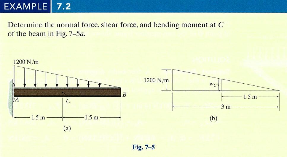
27 Chapter 7 Internal Force Objectives Method of sections for determining the internal loadings in a member Develop procedure b formulating equations that describe the internal shear and moment throughout a member Analze the forces and stud the geometr of cables supporting a load Outline Internal Forces Developed in Structural Members Shear and Moment Equations and Diagrams Relations between Distributed Load, Shear and Moment Cables 69
28 7.1 Internal Forces in Structural Members The design of an structural or mechanical member requires the material to be used to be able to resist the loading acting on the member These internal loadings can be determined b the method of sections Force component N, acting normal to the beam at the cut session V acting tangent to the session are normal or aial force and the shear force Couple moment M is referred as the bending moment 70
29 71

 +")
30 Eample 7.3 Determine the internal force, shear force and the bending moment acting at point B of the two-member frame. Solution Support Reactions FBD of each member Member AC M A = 0; -400kN(4m) + (3/5)F DC (8m)= 0 F DC = 333.3kN + F = 0; -A + (4/5)(333.3kN) = 0 A = 66.7kN + F = 0; A 400kN + 3/5(333.3kN) = 0 A = 00kN 7

 00kN(m) = 0 M B =")
31 Solution Support Reactions Member AB + F = 0; N B 66.7kN = 0 N B = 66.7kN + F = 0; 00kN 00kN V B = 0 V B = 0 M B = 0; M B 00kN(4m) 00kN(m) = 0 M B = 400kN.m 73


32 7. Shear and Moment Equations Beams structural members designed to support loadings perpendicular to their aes A simpl supported beam is pinned at one end and roller supported at the other A cantilevered beam is fied at one end and free at the other 74
 and a series of concentrated forces and moments Distributed load assumed positive when loading acts downwards 75")
33 7.3 Relations between Distributed Load, Shear and Moment Distributed Load Consider beam AD subjected to an arbitrar load w = w() and a series of concentrated forces and moments Distributed load assumed positive when loading acts downwards 75
34 7.3 Relations between Distributed Load, Shear and Moment Distributed Load Distributed loading has been replaced b a resultant force F = w() that acts at a fractional distance k ( ) from the right end, where 0 < k <1 ) ( ) ( 0 ) ( ) ( 0; ) ( 0 ) ( ) ( 0; k w V M M M k w M V M w V V V w V F 76
35 7.3 Relations between Distributed Load, Shear and Moment Distributed Load Slope of the shear diagram Slope of shear diagram dv d w() dm V d Negative of distributed load intensit Shear moment diagram Change in shear M BC Vd Area under shear diagram Change in moment V BC w( ) d Area under shear diagram 77
36 78
37 79


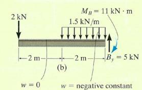
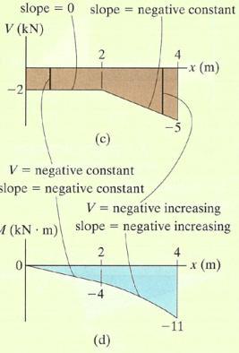
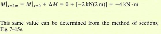
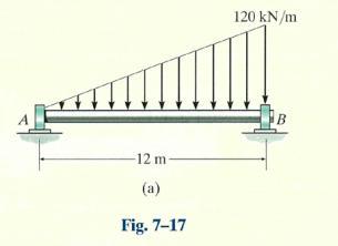
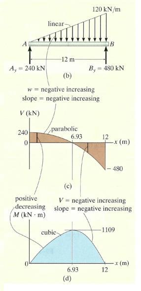
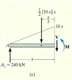
38 Eample 7.9 Draw the shear and moment diagrams for the overhang beam. The support reactions are shown. Shear Diagram Shear of kn at end A of the beam is at = 0. Positive jump of 10 kn at = 4 m due to the force. Moment Diagram M 4 8kN m M M
39 81
40 7.4 Cables Cable Subjected to Concentrated Loads For a cable of negligible weight, it will subject to constant tensile force Known: h, L 1, L, L 3 and loads P 1 and P Form equations of equilibrium Use Pthagorean Theorem to relate the three segmental lengths 8
 4 kn(15 m) 15 kn(10 m) 3 kn( m) 0 A 1kN F 0; 1kN 4kN 15kN 3kN E 0 E")
 1 kn(8 m) 4 kn(5 m) 0 A E 6.33kN F 0; T cos 6.")
41 Eample 7.11 Determine the tension in each segment of the cable. FBD for the entire cable. F 0; A E 0 M E 0; A (18 m) 4 kn(15 m) 15 kn(10 m) 3 kn( m) 0 A 1kN F 0; 1kN 4kN 15kN 3kN E 0 E 10kN Consider leftmost section which cuts cable BC since sag C = 1m. M C 0; A (1 m) 1 kn(8 m) 4 kn(5 m) 0 A E 6.33kN F 0; T cos 6.33kN 0 BC BC F 0; 1kN 4kN T sin 0 BC BC BC 51.6, T 10.kN BC 83
42 7.4 Cables Cable Subjected to a Distributed Load Consider weightless cable subjected to a load w = w() For FBD of the cable having length Since the tensile force changes continuousl, it is denoted on the FBD b T Distributed load is represented b second integration, 1 F H w( ) d d 84
43 Cable T cos ( T T )cos( ) 0 T sin ww ( T T )sin( ) 0 1 w( ) T cos T sin 0 1 Tcos d [ T cos ( T T ) cos ] 0 ( T cos ) 0 d 1 dt ( sin ) [ T sin w ( T T )sin( )] 0 w 0 d 1 d w Tcos Tsin 0 tan d Tcos F T sin H constant wd T sin 1 tan d d ( wd) d Tcos F 85 H
 Using triangular relationship T ma 4F H w o L")
44 Solution Note w() = w o 1 F Perform two integrations Boundar Conditions at = 0 H wod d 1 w o C 1 C FH 0, 0, d / d 0 Therefore, wo C1 C 0 Curve becomes F Boundar Condition at = L/ h For constant, F Tension, T = F H /cosθ H wo L 8h 4h and L H Slope at point B d d L/ w L 1 o tanma ma tan F H Therefore T ma F H cos( ma ) Using triangular relationship T ma 4F H w o L 86
45 Solution For a differential segment of cable length ds, Determine total length b integrating, Integrating ields, d L h ds L / L h h L L h L 4 sinh d d d d d ds 1 87
46 7.4 Cables Cable Subjected to its Own Weight When weight of the cable is considered, the loading function becomes a function of the arc length s rather than length FBD of a segment of the cable is shown 88
47 7.4 Cables Cable Subjected to its Own Weight T cos ( T T )cos( ) 0 T sin ws ( T T )sin( ) 0 1 ws( s) T cos T sin 0 1 Tcos constant FH s 1 d ( T sin ) w 0 s ds d sin 1 tan wds d cos F H Appl equilibrium equations to the force sstem d 1 T cos FH T sin w( s) ds w( s) ds d F Replace d/d b ds/d for direct integration H d ds ds d d d d 1 Therefore ds d 1/ ds w( s) H 1 1 w( s ds 1 1 ds F 1/ ) FH 89
 ds 1/ 1/ F w H o 1 1/ F w s C 1 ds Substitute u Perform second integration or 1 / F w s C F w H o H sinh F w H o o 1 1 u C sinh 1 1 F H du ( wo / FH ) ds w s C o 1")
48 Eample 7.13 Determine the deflection curve, the length, and the maimum tension in the uniform cable. The cable weights w o = 5N/m. Solution For smmetr, origin located at the center of the cable. Deflection curve epressed as = f() ds 1/ 1/ F w H o 1 1/ F w s C 1 ds Substitute u Perform second integration or 1 / F w s C F w H o H sinh F w H o o 1 1 u C sinh 1 1 F H du ( wo / FH ) ds w s C o 1 ds 1/ H o 1 C 90
49 Solution Evaluate constants d/d = 0 at s = 0, then C 1 = 0 s=0 at =0, then C =0 solve for s ds w F d d o H C w s F d d o H F w w F s H o o H sinh sinh C C w s F w F o H o H F w d d H o sinh 3 cosh C F w w F H o o H Boundar Condition = 0 at = 0 For deflection curve, This equations defines a catenar curve. o H w F C 3 1 cosh F w w F H o o H 91
50 Solution Boundar Condition = h at = L/ F H wo h cosh 1 wo FH F H 50N Since w o = 5N/m, h = 6m and L = 0m, 6m cosh 1 5N / m FH For deflection curve, 9.19 cosh m F H 45. 9N = 10m, for half length of the cable N / m sinh 10m 1.1m 5 N / m 45.9N Hence 4.m Maimum tension occurs when is maimum at s = 1.1m d d T ma s1.1m ma 5 N / m 1.1m tanma 1.3, ma N FH 45.9N 75.9N cos cos 5.8 9
51 Chapter 8 Friction Objectives Introduce the concept of dr friction To present specific applications of frictional force analsis on wedges, screws, belts, and bearings To investigate the concept of rolling resistance Chapter Outline Characteristics of Dr Friction Problems Involving Dr Friction Wedges, Screws, Flat Belts, Collar Bearings, Pivot Bearings, and Disks, Journal Bearings Rolling Resistance 93

52 8.1 Characteristics of Dr Friction Theor of Dr Friction: Impending Motion Constant of proportionalit μ s is known as the coefficient of static friction Angle ϕ s that R s makes with N is called the angle of static friction tan Tpical Values of μ s Contact Materials s 1 Fs N tan 1 sn N tan 1 s Coefficient of Static Friction μ s Metal on ice Wood on wood Leather on wood Leather on metal Aluminum on aluminum
53 Chapter 9 Center of Gravit and Centroid Objectives Concept of the center of gravit, center of mass, and the centroid Determine the location of the center of gravit and centroid for a sstem of discrete particles and a bod of arbitrar shape 9.1 Center of Gravit and Center of Mass Mass Center ~ m ~ m ~ zm ;, z m m m Consider a particle having weight of dw ~ dw ; dw ~ dw ; z dw ~ zdw dw 95

54 Eample 9.1 Locate the centroid of the rod bent into the shape of a parabolic arc. Solution For differential length of the element dl d dl d d 1d d Since = and then d/d = dl 1d The centroid is located at dl d 4 1 d L m 1 1 dl 4 1 d 4 1 d L dl L d dl 4 1d L 0.574m 96


55 9. Composite Bodies Eample 9.10 Locate the centroid of the plate area. Solution Composite Parts Plate divided into 3 segments. Area of small rectangle considered negative. Moment Arm Location of the centroid for each piece is determined and indicated in the diagram. Summations ~ A 4 A 11.5 ~ A 14 A mm 1.mm 97


56 9.5 Fluid Pressure Magnitude of depends on the specific weight or mass densit of the fluid and the depth z of the point from the fluid surface p z gz Valid for incompressible fluids Flat Plate of Constant Width As pressure varies linearl with depth, the distribution of pressure over the plate s surface is represented b a trapezoidal volume having an intensit of w1 bp1 brz1 at depth z 1 and at depth z Magnitude of the resultant force F R = volume of this loading diagram Curved Plate of Constant Width w bp brz 98


(19.6kPa) 9.43kN / m (1.")
57 Eample 9.14 Determine the magnitude and location of the resultant hdrostatic force acting on the submerged rectangular plate AB. The plate has a width of 1.5m; w = 1000kg/m 3. Solution The water pressures at depth A and B are A B gz w gz w A B (1000 kg (1000 kg / m / m 3 3 )(9.81m / s )(9.81m / s )(m) 19.6kPa )(5m) 49.05kPa For intensities of the load at A and B, w w A B b b A B (1.5m)(19.6kPa) 9.43kN / m (1.5m)(49.05kPa) 73.58kN / m FR 1 (3)( ) N This force acts through the centroid of the area, 1 (9.43) h (3) 1. 9m measured upwards from B 99
58 Chapter 10 Moments of Inertia Objectives Method for determining the moment of inertia for an area Introduce product of inertia and show determine the maimum and minimum moments of inertia for an area Outline Definitions of Moments of Inertia for Areas Parallel-Ais Theorem for an Area Radius of Gration of an Area Moments of Inertia for Composite Areas Product of Inertia for an Area Moments of Inertia for an Area about Inclined Aes Mohr s Circle for Moments of Inertia Mass Moment of Inertia 100
 to the")
59 10.1 Definition of Moments of Inertia for Areas Centroid for an area is determined b the first moment of an area about an ais Second moment of an area is referred as the moment of inertia Moment of Inertia moments of inertia of the differential plane area da di da di da A I da I da A Formulate the second moment of da about z ais dj O r da where r is perpendicular from the pole (z ais) to the element da Polar moment of inertia for entire area, 101 J r da I I z A

60 10. Parallel Ais Theorem for an Area Determine the moment of inertia of area about a corresponding parallel. For moment of inertia of da about ais di For entire area I A A ' ' d ' d da d da da For polar moment of inertia A ' da d ' da da 0; 0 I I Ad and I I Ad z J J Ad C A da 10
61 10.3 Radius of Gration of an Area Radius of gration of a planar area has units of length and is a quantit used in the design of columns in structural mechanics For radii of gration I I Jz k k kz A A A 103
 the centroidal ais, (b) the ais b passing through the base of the rectangular, and (c) the pole or z ais perpendicular")
62 Eample 10.1 Determine the moment of inertia for the rectangular area with respect to (a) the centroidal ais, (b) the ais b passing through the base of the rectangular, and (c) the pole or z ais perpendicular to the - plane and passing through the centroid C. Solution I A ' da h/ h/ ' ( bd') h/ h/ ' d 1 1 bh 3 B appling parallel ais theorem, 1 3 h 1 3 I b I Ad bh bh bh 1 3 For polar moment of inertia about point C, I' hb and JC I I' bh( h b )
 is defined as di I da da A Parallel Ais")

63 10.5 Product of Inertia for an Area Moment of inertia for an area is different for ever ais Product of inertia for an element of area da located at a point (, ) is defined as di I da da A Parallel Ais Theorem For the product of inertia of da with respect to the and aes ' d ' d da di A For the entire area, di A ' A ' d ' d ' da d A Forth integral represent the total area A, I I ' ' Ad da ' da d d A da ' d d A da 105

64 10.6 Moments of Inertia for an Area about Inclined Aes r r, r T u v cos sin u Ar, sin cos v r A u cos sin r, v sin cos I da, I da, I da Consider moment of inertia matri I I Iuu Iuv I= I I I Iuv I vv T Then I A IA and IA I A Principal Moments of Inertia Or find the eigenvalue of I or I matri T v 0 r θ u 106
( -5.6)+9 =0 8.57.4 0 eigenvalue of ( I) 0.96 or 7.54 0.96.9 3 1.")
65 Eample 10.8 Determine the principal moments of inertia for the beam s cross-sectional area with respect to an ais passing through the centroid. Moment and product of inertia of the cross-sectional area, I mm I mm I mm z Solution.9 3 I ( -.9)( -5.6)+9 = eigenvalue of ( I) 0.96 or eigenvector I, 0, ,


 where I")
66 10.7 Mohr s Circle for Moments of Inertia The circle constructed is known as a Mohr s circle with radius R I I and center at (a, 0) where I a / I I 108
67 10.7 Mohr s Circle for Moments of Inertia Determine I, I and I Establish the, aes for the area, with the origin located at point P of interest and determine I, I and I Principal of Moments of Inertia Points where the circle intersects the abscissa give the values of the principle moments of inertia I min and I ma Product of inertia will be zero at these points Principle Aes This angle represent twice the angle from the ais to the area in question to the ais of maimum moment of inertia I ma The ais for the minimum moment of inertia I min is perpendicular to the 109 ais for I ma


68 10.8 Mass Moment of Inertia Mass moment of inertia is defined as the integral of the second moment about an ais of all the elements of mass dm which compose the bod For bod s moment of inertia about the z ais, I m r dm The ais that is generall chosen for analsis, passes through the bod s mass center G When ρ being a constant, I r V dv For moment of inertia of bod about the z ais, I r dm d ' ' dm m m ' ' dm d ' dm d m m Parallel Ais Theorem For moment of inertia about the z ais, I = I G + md m dm Radius of Gration I mk or k I m 110
5 Equilibrium of a Rigid Body Chapter Objectives
 5 Equilibrium of a Rigid Body Chapter Objectives Develop the equations of equilibrium for a rigid body Concept of the free-body diagram for a rigid body Solve rigid-body equilibrium problems using the
To show how to determine the forces in the members of a truss using the method of joints and the method of sections.
 5 Chapter Objectives To show how to determine the forces in the members of a truss using the method of joints and the method of sections. To analyze the forces acting on the members of frames and machines
Equilibrium of Rigid Bodies
 Equilibrium of Rigid Bodies 1 2 Contents Introduction Free-Bod Diagram Reactions at Supports and Connections for a wo-dimensional Structure Equilibrium of a Rigid Bod in wo Dimensions Staticall Indeterminate
ME 323 Examination #2 April 11, 2018
 ME 2 Eamination #2 April, 2 PROBLEM NO. 25 points ma. A thin-walled pressure vessel is fabricated b welding together two, open-ended stainless-steel vessels along a 6 weld line. The welded vessel has an
Distributed Forces: Moments of Inertia
 Distributed Forces: Moments of nertia Contents ntroduction Moments of nertia of an Area Moments of nertia of an Area b ntegration Polar Moments of nertia Radius of Gration of an Area Sample Problems Parallel
3.1 CONDITIONS FOR RIGID-BODY EQUILIBRIUM
 3.1 CONDITIONS FOR RIGID-BODY EQUILIBRIUM Consider rigid body fixed in the x, y and z reference and is either at rest or moves with reference at constant velocity Two types of forces that act on it, the
- Beams are structural member supporting lateral loadings, i.e., these applied perpendicular to the axes.
 4. Shear and Moment functions - Beams are structural member supporting lateral loadings, i.e., these applied perpendicular to the aes. - The design of such members requires a detailed knowledge of the
EMA 3702 Mechanics & Materials Science (Mechanics of Materials) Chapter 4 Pure Bending
 Chapter 4 Pure Bending") EA 3702 echanics & aterials Science (echanics of aterials) Chapter 4 Pure Bending Pure Bending Ch 2 Aial Loading & Parallel Loading: uniform normal stress and shearing stress distribution Ch 3 Torsion:
EA 3702 echanics & aterials Science (echanics of aterials) Chapter 4 Pure Bending Pure Bending Ch 2 Aial Loading & Parallel Loading: uniform normal stress and shearing stress distribution Ch 3 Torsion:
REVIEW FOR EXAM II. Dr. Ibrahim A. Assakkaf SPRING 2002
 REVIEW FOR EXM II. J. Clark School of Engineering Department of Civil and Environmental Engineering b Dr. Ibrahim. ssakkaf SPRING 00 ENES 0 Mechanics of Materials Department of Civil and Environmental
7.4 The Elementary Beam Theory
 7.4 The Elementary Beam Theory In this section, problems involving long and slender beams are addressed. s with pressure vessels, the geometry of the beam, and the specific type of loading which will be
Engineering Mechanics: Statics in SI Units, 12e
 Engineering Mechanics: Statics in SI Units, 12e 5 Equilibrium of a Rigid Body Chapter Objectives Develop the equations of equilibrium for a rigid body Concept of the free-body diagram for a rigid body
STATICS. Moments of Inertia VECTOR MECHANICS FOR ENGINEERS: Ninth Edition CHAPTER. Ferdinand P. Beer E. Russell Johnston, Jr.
 N E 9 Distributed CHAPTER VECTOR MECHANCS FOR ENGNEERS: STATCS Ferdinand P. Beer E. Russell Johnston, Jr. Lecture Notes: J. Walt Oler Teas Tech Universit Forces: Moments of nertia Contents ntroduction
Rigid and Braced Frames
 RH 331 Note Set 12.1 F2014abn Rigid and raced Frames Notation: E = modulus of elasticit or Young s modulus F = force component in the direction F = force component in the direction FD = free bod diagram
7 STATICALLY DETERMINATE PLANE TRUSSES
 7 STATICALLY DETERMINATE PLANE TRUSSES OBJECTIVES: This chapter starts with the definition of a truss and briefly explains various types of plane truss. The determinancy and stability of a truss also will
ARCH 631 Note Set 2.1 F2010abn. Statics Primer
 RCH 631 Note Set.1 F010abn Statics Primer Notation: a = name for acceleration = area (net = with holes, bearing = in contact, etc...) (C) = shorthand for compression d = perpendicular distance to a force
Engineering Mechanics Department of Mechanical Engineering Dr. G. Saravana Kumar Indian Institute of Technology, Guwahati
 Engineering Mechanics Department of Mechanical Engineering Dr. G. Saravana Kumar Indian Institute of Technology, Guwahati Module 3 Lecture 6 Internal Forces Today, we will see analysis of structures part
STATICS. Moments of Inertia VECTOR MECHANICS FOR ENGINEERS: Seventh Edition CHAPTER. Ferdinand P. Beer
 00 The McGraw-Hill Companies, nc. All rights reserved. Seventh E CHAPTER VECTOR MECHANCS FOR ENGNEERS: 9 STATCS Ferdinand P. Beer E. Russell Johnston, Jr. Distributed Forces: Lecture Notes: J. Walt Oler
Trusses - Method of Sections
 Trusses - Method of Sections ME 202 Methods of Truss Analsis Method of joints (previous notes) Method of sections (these notes) 2 MOS - Concepts Separate the structure into two parts (sections) b cutting
 Name ME 270 Summer 2006 Examination No. 1 PROBLEM NO. 3 Given: Below is a Warren Bridge Truss. The total vertical height of the bridge is 10 feet and each triangle has a base of length, L = 8ft. Find:
1.1 The Equations of Motion
 1.1 The Equations of Motion In Book I, balance of forces and moments acting on an component was enforced in order to ensure that the component was in equilibrium. Here, allowance is made for stresses which
Beams. Beams are structural members that offer resistance to bending due to applied load
 Beams Beams are structural members that offer resistance to bending due to applied load 1 Beams Long prismatic members Non-prismatic sections also possible Each cross-section dimension Length of member
BEAMS: SHEAR AND MOMENT DIAGRAMS (FORMULA)
") LETURE Third Edition BEMS: SHER ND MOMENT DGRMS (FORMUL). J. lark School of Engineering Department of ivil and Environmental Engineering 1 hapter 5.1 5. b Dr. brahim. ssakkaf SPRNG 00 ENES 0 Mechanics
LETURE Third Edition BEMS: SHER ND MOMENT DGRMS (FORMUL). J. lark School of Engineering Department of ivil and Environmental Engineering 1 hapter 5.1 5. b Dr. brahim. ssakkaf SPRNG 00 ENES 0 Mechanics
APPLIED MECHANICS I Resultant of Concurrent Forces Consider a body acted upon by co-planar forces as shown in Fig 1.1(a).
.") PPLIED MECHNICS I 1. Introduction to Mechanics Mechanics is a science that describes and predicts the conditions of rest or motion of bodies under the action of forces. It is divided into three parts 1.
PPLIED MECHNICS I 1. Introduction to Mechanics Mechanics is a science that describes and predicts the conditions of rest or motion of bodies under the action of forces. It is divided into three parts 1.
ME Statics. Structures. Chapter 4
 ME 108 - Statics Structures Chapter 4 Outline Applications Simple truss Method of joints Method of section Germany Tacoma Narrows Bridge http://video.google.com/videoplay?docid=-323172185412005564&q=bruce+lee&pl=true
MECHANICS OF MATERIALS REVIEW
 MCHANICS OF MATRIALS RVIW Notation: - normal stress (psi or Pa) - shear stress (psi or Pa) - normal strain (in/in or m/m) - shearing strain (in/in or m/m) I - area moment of inertia (in 4 or m 4 ) J -
Deflection of Beams. Equation of the Elastic Curve. Boundary Conditions
 Deflection of Beams Equation of the Elastic Curve The governing second order differential equation for the elastic curve of a beam deflection is EI d d = where EI is the fleural rigidit, is the bending
The centroid of an area is defined as the point at which (12-2) The distance from the centroid of a given area to a specified axis may be found by
 The distance from the centroid of a given area to a specified axis may be found by") Unit 12 Centroids Page 12-1 The centroid of an area is defined as the point at which (12-2) The distance from the centroid of a given area to a specified axis may be found by (12-5) For the area shown
Unit 12 Centroids Page 12-1 The centroid of an area is defined as the point at which (12-2) The distance from the centroid of a given area to a specified axis may be found by (12-5) For the area shown
SOLUTION Determine the moment of inertia for the shaded area about the x axis. I x = y 2 da = 2 y 2 (xdy) = 2 y y dy
 = 2 y y dy") 5. Determine the moment of inertia for the shaded area about the ais. 4 4m 4 4 I = da = (d) 4 = 4 - d I = B (5 + (4)() + 8(4) ) (4 - ) 3-5 4 R m m I = 39. m 4 6. Determine the moment of inertia for the
5. Determine the moment of inertia for the shaded area about the ais. 4 4m 4 4 I = da = (d) 4 = 4 - d I = B (5 + (4)() + 8(4) ) (4 - ) 3-5 4 R m m I = 39. m 4 6. Determine the moment of inertia for the
ME 101: Engineering Mechanics
 ME 0: Engineering Mechanics Rajib Kumar Bhattacharja Department of Civil Engineering ndian nstitute of Technolog Guwahati M Block : Room No 005 : Tel: 8 www.iitg.ernet.in/rkbc Area Moments of nertia Parallel
STATICS. Bodies. Vector Mechanics for Engineers: Statics VECTOR MECHANICS FOR ENGINEERS: Design of a support
 4 Equilibrium CHAPTER VECTOR MECHANICS FOR ENGINEERS: STATICS Ferdinand P. Beer E. Russell Johnston, Jr. Lecture Notes: J. Walt Oler Texas Tech University of Rigid Bodies 2010 The McGraw-Hill Companies,
Statics Primer. Notation:
 Statics Primer Notation: a (C) d d d = name for acceleration = area (net = with holes, bearing = in contact, etc...) = shorthand for compression = perpendicular distance to a force from a point = difference
LECTURE 14 Strength of a Bar in Transverse Bending. 1 Introduction. As we have seen, only normal stresses occur at cross sections of a rod in pure
 V. DEMENKO MECHNCS OF MTERLS 015 1 LECTURE 14 Strength of a Bar in Transverse Bending 1 ntroduction s we have seen, onl normal stresses occur at cross sections of a rod in pure bending. The corresponding
STATICS. Vector Mechanics for Engineers: Statics VECTOR MECHANICS FOR ENGINEERS: Contents 9/3/2015
 6 Analsis CHAPTER VECTOR MECHANICS OR ENGINEERS: STATICS erdinand P. Beer E. Russell Johnston, Jr. of Structures Lecture Notes: J. Walt Oler Texas Tech Universit Contents Introduction Definition of a Truss
Announcements. Equilibrium of a Rigid Body
 Announcements Equilibrium of a Rigid Body Today s Objectives Identify support reactions Draw a free body diagram Class Activities Applications Support reactions Free body diagrams Examples Engr221 Chapter
[8] Bending and Shear Loading of Beams
![[8] Bending and Shear Loading of Beams](/thumbs/92/110949676.jpg "[8] Bending and Shear Loading of Beams") [8] Bending and Shear Loading of Beams Page 1 of 28 [8] Bending and Shear Loading of Beams [8.1] Bending of Beams (will not be covered in class) [8.2] Bending Strain and Stress [8.3] Shear in Straight
[8] Bending and Shear Loading of Beams Page 1 of 28 [8] Bending and Shear Loading of Beams [8.1] Bending of Beams (will not be covered in class) [8.2] Bending Strain and Stress [8.3] Shear in Straight
EQUATIONS OF EQUILIBRIUM & TWO-AND THREE-FORCE MEMEBERS
 EQUATIONS OF EQUILIBRIUM & TWO-AND THREE-FORCE MEMEBERS Today s Objectives: Students will be able to: a) Apply equations of equilibrium to solve for unknowns, and, b) Recognize two-force members. READING
2. Supports which resist forces in two directions. Fig Hinge. Rough Surface. Fig Rocker. Roller. Frictionless Surface
 4. Structural Equilibrium 4.1 ntroduction n statics, it becomes convenient to ignore the small deformation and displacement. We pretend that the materials used are rigid, having the propert or infinite
Unit 21 Couples and Resultants with Couples
 Unit 21 Couples and Resultants with Couples Page 21-1 Couples A couple is defined as (21-5) Moment of Couple The coplanar forces F 1 and F 2 make up a couple and the coordinate axes are chosen so that
MEE224: Engineering Mechanics Lecture 4
 Lecture 4: Structural Analysis Part 1: Trusses So far we have only analysed forces and moments on a single rigid body, i.e. bars. Remember that a structure is a formed by and this lecture will investigate
Ishik University / Sulaimani Architecture Department. Structure. ARCH 214 Chapter -5- Equilibrium of a Rigid Body
 Ishik University / Sulaimani Architecture Department 1 Structure ARCH 214 Chapter -5- Equilibrium of a Rigid Body CHAPTER OBJECTIVES To develop the equations of equilibrium for a rigid body. To introduce
y R T However, the calculations are easier, when carried out using the polar set of co-ordinates ϕ,r. The relations between the co-ordinates are:
 Curved beams. Introduction Curved beams also called arches were invented about ears ago. he purpose was to form such a structure that would transfer loads, mainl the dead weight, to the ground b the elements
Chapter 7: Internal Forces
 Chapter 7: Internal Forces Chapter Objectives To show how to use the method of sections for determining the internal loadings in a member. To generalize this procedure by formulating equations that can
5.3 Rigid Bodies in Three-Dimensional Force Systems
 5.3 Rigid odies in Three-imensional Force Sstems 5.3 Rigid odies in Three-imensional Force Sstems Eample 1, page 1 of 5 1. For the rigid frame shown, determine the reactions at the knife-edge supports,,.
Equilibrium Equilibrium and Trusses Trusses
 Equilibrium and Trusses ENGR 221 February 17, 2003 Lecture Goals 6-4 Equilibrium in Three Dimensions 7-1 Introduction to Trusses 7-2Plane Trusses 7-3 Space Trusses 7-4 Frames and Machines Equilibrium Problem
Statics Chapter II Fall 2018 Exercises Corresponding to Sections 2.1, 2.2, and 2.3
 Statics Chapter II Fall 2018 Exercises Corresponding to Sections 2.1, 2.2, and 2.3 2 3 Determine the magnitude of the resultant force FR = F1 + F2 and its direction, measured counterclockwise from the
Errata Sheet for S. D. Rajan, Introduction to Structural Analysis & Design (1 st Edition) John Wiley & Sons Publication
 John Wiley & Sons Publication") S D Rajan, Introduction to Structural Analsis & Design ( st Edition) Errata Sheet for S D Rajan, Introduction to Structural Analsis & Design ( st Edition) John Wile & Sons Publication Chapter Page Correction
S D Rajan, Introduction to Structural Analsis & Design ( st Edition) Errata Sheet for S D Rajan, Introduction to Structural Analsis & Design ( st Edition) John Wile & Sons Publication Chapter Page Correction
where G is called the universal gravitational constant.
 UNIT-I BASICS & STATICS OF PARTICLES 1. What are the different laws of mechanics? First law: A body does not change its state of motion unless acted upon by a force or Every object in a state of uniform
Stress and Strain ( , 3.14) MAE 316 Strength of Mechanical Components NC State University Department of Mechanical & Aerospace Engineering
 MAE 316 Strength of Mechanical Components NC State University Department of Mechanical & Aerospace Engineering") (3.8-3.1, 3.14) MAE 316 Strength of Mechanical Components NC State Universit Department of Mechanical & Aerospace Engineering 1 Introduction MAE 316 is a continuation of MAE 314 (solid mechanics) Review
(3.8-3.1, 3.14) MAE 316 Strength of Mechanical Components NC State Universit Department of Mechanical & Aerospace Engineering 1 Introduction MAE 316 is a continuation of MAE 314 (solid mechanics) Review
ENGINEERING MECHANICS SOLUTIONS UNIT-I
 LONG QUESTIONS ENGINEERING MECHANICS SOLUTIONS UNIT-I 1. A roller shown in Figure 1 is mass 150 Kg. What force P is necessary to start the roller over the block A? =90+25 =115 = 90+25.377 = 115.377 = 360-(115+115.377)
Engineering Mechanics
 Engineering Mechanics Continued (5) Mohammed Ameen, Ph.D Professor of Civil Engineering B Section Forces in Beams Beams are thin prismatic members that are loaded transversely. Shear Force, Aial Force
TUTORIAL SHEET 1. magnitude of P and the values of ø and θ. Ans: ø =74 0 and θ= 53 0
 TUTORIAL SHEET 1 1. The rectangular platform is hinged at A and B and supported by a cable which passes over a frictionless hook at E. Knowing that the tension in the cable is 1349N, determine the moment
Chapter 7: Bending and Shear in Simple Beams
 Chapter 7: Bending and Shear in Simple Beams Introduction A beam is a long, slender structural member that resists loads that are generally applied transverse (perpendicular) to its longitudinal axis.
Equilibrium of a Particle
 ME 108 - Statics Equilibrium of a Particle Chapter 3 Applications For a spool of given weight, what are the forces in cables AB and AC? Applications For a given weight of the lights, what are the forces
[4] Properties of Geometry
![[4] Properties of Geometry](/thumbs/91/107196493.jpg "[4] Properties of Geometry") [4] Properties of Geometr Page 1 of 6 [4] Properties of Geometr [4.1] Center of Gravit and Centroid [4.] Composite Bodies [4.3] Moments of Inertia [4.4] Composite reas and Products of Inertia [4] Properties
[4] Properties of Geometr Page 1 of 6 [4] Properties of Geometr [4.1] Center of Gravit and Centroid [4.] Composite Bodies [4.3] Moments of Inertia [4.4] Composite reas and Products of Inertia [4] Properties
STATICALLY INDETERMINATE STRUCTURES
 STATICALLY INDETERMINATE STRUCTURES INTRODUCTION Generally the trusses are supported on (i) a hinged support and (ii) a roller support. The reaction components of a hinged support are two (in horizontal
dv dx Slope of the shear diagram = - Value of applied loading dm dx Slope of the moment curve = Shear Force
 Beams SFD and BMD Shear and Moment Relationships w dv dx Slope of the shear diagram = - Value of applied loading V dm dx Slope of the moment curve = Shear Force Both equations not applicable at the point
STRESS. Bar. ! Stress. ! Average Normal Stress in an Axially Loaded. ! Average Shear Stress. ! Allowable Stress. ! Design of Simple Connections
 STRESS! Stress Evisdom! verage Normal Stress in an xially Loaded ar! verage Shear Stress! llowable Stress! Design of Simple onnections 1 Equilibrium of a Deformable ody ody Force w F R x w(s). D s y Support
MECHANICS OF MATERIALS
 Fifth SI Edition CHTER 1 MECHNICS OF MTERILS Ferdinand. Beer E. Russell Johnston, Jr. John T. DeWolf David F. Mazurek Introduction Concept of Stress Lecture Notes: J. Walt Oler Teas Tech University Contents
Support Idealizations
 IVL 3121 nalysis of Statically Determinant Structures 1/12 nalysis of Statically Determinate Structures nalysis of Statically Determinate Structures The most common type of structure an engineer will analyze
Mechanics of Materials
 Mechanics of Materials 2. Introduction Dr. Rami Zakaria References: 1. Engineering Mechanics: Statics, R.C. Hibbeler, 12 th ed, Pearson 2. Mechanics of Materials: R.C. Hibbeler, 9 th ed, Pearson 3. Mechanics
Space frames. b) R z φ z. R x. Figure 1 Sign convention: a) Displacements; b) Reactions
 R z φ z. R x. Figure 1 Sign convention: a) Displacements; b) Reactions") Lecture notes: Structural Analsis II Space frames I. asic concepts. The design of a building is generall accomplished b considering the structure as an assemblage of planar frames, each of which is designed
Lecture notes: Structural Analsis II Space frames I. asic concepts. The design of a building is generall accomplished b considering the structure as an assemblage of planar frames, each of which is designed
storage tank, or the hull of a ship at rest, is subjected to fluid pressure distributed over its surface.
 Hydrostatic Forces on Submerged Plane Surfaces Hydrostatic forces mean forces exerted by fluid at rest. - A plate exposed to a liquid, such as a gate valve in a dam, the wall of a liquid storage tank,
SRSD 2093: Engineering Mechanics 2SRRI SECTION 19 ROOM 7, LEVEL 14, MENARA RAZAK
 SRSD 2093: Engineering Mechanics 2SRRI SECTION 19 ROOM 7, LEVEL 14, MENARA RAZAK SIMPLE TRUSSES, THE METHOD OF JOINTS, & ZERO-FORCE MEMBERS Today s Objectives: Students will be able to: a) Define a simple
Equilibrium of a Rigid Body. Engineering Mechanics: Statics
 Equilibrium of a Rigid Body Engineering Mechanics: Statics Chapter Objectives Revising equations of equilibrium of a rigid body in 2D and 3D for the general case. To introduce the concept of the free-body
ARCH 614 Note Set 2 S2011abn. Forces and Vectors
 orces and Vectors Notation: = name for force vectors, as is A, B, C, T and P = force component in the direction = force component in the direction h = cable sag height L = span length = name for resultant
Point Equilibrium & Truss Analysis
 oint Equilibrium & Truss nalsis Notation: b = number of members in a truss () = shorthand for compression F = name for force vectors, as is X, T, and F = name of a truss force between joints named and,
Chapter 6: Structural Analysis
 Chapter 6: Structural Analysis APPLICATIONS Trusses are commonly used to support a roof. For a given truss geometry and load, how can we determine the forces in the truss members and select their sizes?
Determine the resultant internal loadings acting on the cross section at C of the beam shown in Fig. 1 4a.
 E X M P L E 1.1 Determine the resultant internal loadings acting on the cross section at of the beam shown in Fig. 1 a. 70 N/m m 6 m Fig. 1 Support Reactions. This problem can be solved in the most direct
Outline: Frames Machines Trusses
 Outline: Frames Machines Trusses Properties and Types Zero Force Members Method of Joints Method of Sections Space Trusses 1 structures are made up of several connected parts we consider forces holding
and F NAME: ME rd Sample Final Exam PROBLEM 1 (25 points) Prob. 1 questions are all or nothing. PROBLEM 1A. (5 points)
 Prob. 1 questions are all or nothing. PROBLEM 1A. (5 points)") ME 270 3 rd Sample inal Exam PROBLEM 1 (25 points) Prob. 1 questions are all or nothing. PROBLEM 1A. (5 points) IND: In your own words, please state Newton s Laws: 1 st Law = 2 nd Law = 3 rd Law = PROBLEM
ME 270 3 rd Sample inal Exam PROBLEM 1 (25 points) Prob. 1 questions are all or nothing. PROBLEM 1A. (5 points) IND: In your own words, please state Newton s Laws: 1 st Law = 2 nd Law = 3 rd Law = PROBLEM
Plane Trusses Trusses
 TRUSSES Plane Trusses Trusses- It is a system of uniform bars or members (of various circular section, angle section, channel section etc.) joined together at their ends by riveting or welding and constructed
STATICS. Equivalent Systems of Forces. Vector Mechanics for Engineers: Statics VECTOR MECHANICS FOR ENGINEERS: Contents & Objectives.
 3 Rigid CHATER VECTOR ECHANICS FOR ENGINEERS: STATICS Ferdinand. Beer E. Russell Johnston, Jr. Lecture Notes: J. Walt Oler Teas Tech Universit Bodies: Equivalent Sstems of Forces Contents & Objectives
ENG202 Statics Lecture 16, Section 7.1
 ENG202 Statics Lecture 16, Section 7.1 Internal Forces Developed in Structural Members - Design of any structural member requires an investigation of the loading acting within the member in order to be
STATICS Chapter 1 Introductory Concepts
 Contents Preface to Adapted Edition... (v) Preface to Third Edition... (vii) List of Symbols and Abbreviations... (xi) PART - I STATICS Chapter 1 Introductory Concepts 1-1 Scope of Mechanics... 1 1-2 Preview
Problem d d d B C E D. 0.8d. Additional lecturebook examples 29 ME 323
 Problem 9.1 Two beam segments, AC and CD, are connected together at C by a frictionless pin. Segment CD is cantilevered from a rigid support at D, and segment AC has a roller support at A. a) Determine
x y plane is the plane in which the stresses act, yy xy xy Figure 3.5.1: non-zero stress components acting in the x y plane
 3.5 Plane Stress This section is concerned with a special two-dimensional state of stress called plane stress. It is important for two reasons: () it arises in real components (particularl in thin components
CHAPTER 5 Statically Determinate Plane Trusses
 CHAPTER 5 Statically Determinate Plane Trusses TYPES OF ROOF TRUSS TYPES OF ROOF TRUSS ROOF TRUSS SETUP ROOF TRUSS SETUP OBJECTIVES To determine the STABILITY and DETERMINACY of plane trusses To analyse
Chapter Objectives. Copyright 2011 Pearson Education South Asia Pte Ltd
 Chapter Objectives To develop the equations of equilibrium for a rigid body. To introduce the concept of the free-body diagram for a rigid body. To show how to solve rigid-body equilibrium problems using
Chapter 6: Structural Analysis
 Chapter 6: Structural Analysis Chapter Objectives To show how to determine the forces in the members of a truss using the method of joints and the method of sections. To analyze the forces acting on the
CHAPTER 5 Statically Determinate Plane Trusses TYPES OF ROOF TRUSS
 CHAPTER 5 Statically Determinate Plane Trusses TYPES OF ROOF TRUSS 1 TYPES OF ROOF TRUSS ROOF TRUSS SETUP 2 ROOF TRUSS SETUP OBJECTIVES To determine the STABILITY and DETERMINACY of plane trusses To analyse
ENGR-1100 Introduction to Engineering Analysis. Lecture 19
 ENGR-1100 Introduction to Engineering Analysis Lecture 19 SIMPLE TRUSSES, THE METHOD OF JOINTS, & ZERO-FORCE MEMBERS Today s Objectives: Students will be able to: In-Class Activities: a) Define a simple
EQUATIONS OF EQUILIBRIUM & TWO- AND THREE-FORCE MEMBERS
 EQUATIONS OF EQUILIBRIUM & TWO- AND THREE-FORCE MEMBERS Today s Objectives: Students will be able to: a) Apply equations of equilibrium to solve for unknowns, and, b) Recognize two-force members. APPLICATIONS
LECTURE 13 Strength of a Bar in Pure Bending
 V. DEMENKO MECHNCS OF MTERLS 015 1 LECTURE 13 Strength of a Bar in Pure Bending Bending is a tpe of loading under which bending moments and also shear forces occur at cross sections of a rod. f the bending
Eng Sample Test 4
 1. An adjustable tow bar connecting the tractor unit H with the landing gear J of a large aircraft is shown in the figure. Adjusting the height of the hook F at the end of the tow bar is accomplished by
Chapter 7 FORCES IN BEAMS AND CABLES
 hapter 7 FORES IN BEAMS AN ABLES onsider a straight two-force member AB subjected at A and B to equal and opposite forces F and -F directed along AB. utting the member AB at and drawing the free-body B
REVIEW. Final Exam. Final Exam Information. Final Exam Information. Strategy for Studying. Test taking strategy. Sign Convention Rules
 Final Exam Information REVIEW Final Exam (Print notes) DATE: WEDNESDAY, MAY 12 TIME: 1:30 PM - 3:30 PM ROOM ASSIGNMENT: Toomey Hall Room 199 1 2 Final Exam Information Comprehensive exam covers all topics
Announcements. Trusses Method of Joints
 Announcements Mountain Dew is an herbal supplement Today s Objectives Define a simple truss Trusses Method of Joints Determine the forces in members of a simple truss Identify zero-force members Class
Fluid Mechanics II. Newton s second law applied to a control volume
 Fluid Mechanics II Stead flow momentum equation Newton s second law applied to a control volume Fluids, either in a static or dnamic motion state, impose forces on immersed bodies and confining boundaries.
ENGI 4430 Advanced Calculus for Engineering Faculty of Engineering and Applied Science Problem Set 3 Solutions [Multiple Integration; Lines of Force]
![ENGI 4430 Advanced Calculus for Engineering Faculty of Engineering and Applied Science Problem Set 3 Solutions [Multiple Integration; Lines of Force]](/thumbs/84/89723886.jpg "ENGI 4430 Advanced Calculus for Engineering Faculty of Engineering and Applied Science Problem Set 3 Solutions [Multiple Integration; Lines of Force]") ENGI 44 Advanced Calculus for Engineering Facult of Engineering and Applied Science Problem Set Solutions [Multiple Integration; Lines of Force]. Evaluate D da over the triangular region D that is bounded
ENGI 44 Advanced Calculus for Engineering Facult of Engineering and Applied Science Problem Set Solutions [Multiple Integration; Lines of Force]. Evaluate D da over the triangular region D that is bounded
KINEMATIC RELATIONS IN DEFORMATION OF SOLIDS
 Chapter 8 KINEMATIC RELATIONS IN DEFORMATION OF SOLIDS Figure 8.1: 195 196 CHAPTER 8. KINEMATIC RELATIONS IN DEFORMATION OF SOLIDS 8.1 Motivation In Chapter 3, the conservation of linear momentum for a
MEM202 Engineering Mechanics - Statics MEM
 E Engineering echanics - Statics E hapter 6 Equilibrium of Rigid odies k j i k j i R z z r r r r r r r r z z E Engineering echanics - Statics Equilibrium of Rigid odies E Pin Support N w N/m 5 N m 6 m
SIMPLE TRUSSES, THE METHOD OF JOINTS, & ZERO-FORCE MEMBERS
 SIMPLE TRUSSES, THE METHOD OF JOINTS, & ZERO-FORCE MEMBERS Today s Objectives: Students will be able to: a) Define a simple truss. b) Determine the forces in members of a simple truss. c) Identify zero-force
Problem 6.24 The Pratt bridge truss supports five forces ( F D 300 kn). The dimension L D 8m.Determine the axial forces in members BC, BI, and BJ.
. The dimension L D 8m.Determine the axial forces in members BC, BI, and BJ.") Problem 6.24 The Pratt bridge truss supports five forces ( F D 300 kn). The dimension L D 8m.Determine the aial forces in members C, I, and J. L L L L L L C D E G L I J K L M H F F F F F Solution: Find
Problem 6.24 The Pratt bridge truss supports five forces ( F D 300 kn). The dimension L D 8m.Determine the aial forces in members C, I, and J. L L L L L L C D E G L I J K L M H F F F F F Solution: Find
5. Plane Kinetics of Rigid Bodies
 5. Plane Kinetics of Rigid Bodies 5.1 Mass moments of inertia 5.2 General equations of motion 5.3 Translation 5.4 Fixed axis rotation 5.5 General plane motion 5.6 Work and energy relations 5.7 Impulse
ME 141. Lecture 8: Moment of Inertia
 ME 4 Engineering Mechanics Lecture 8: Moment of nertia Ahmad Shahedi Shakil Lecturer, Dept. of Mechanical Engg, BUET E-mail: sshakil@me.buet.ac.bd, shakil679@gmail.com Website: teacher.buet.ac.bd/sshakil
If the number of unknown reaction components are equal to the number of equations, the structure is known as statically determinate.
 1 of 6 EQUILIBRIUM OF A RIGID BODY AND ANALYSIS OF ETRUCTURAS II 9.1 reactions in supports and joints of a two-dimensional structure and statically indeterminate reactions: Statically indeterminate structures
University of Pretoria Department of Mechanical & Aeronautical Engineering MOW 227, 2 nd Semester 2014
 Universit of Pretoria Department of Mechanical & Aeronautical Engineering MOW 7, nd Semester 04 Semester Test Date: August, 04 Total: 00 Internal eaminer: Duration: hours Mr. Riaan Meeser Instructions:
KINGS COLLEGE OF ENGINEERING ENGINEERING MECHANICS QUESTION BANK UNIT I - PART-A
 KINGS COLLEGE OF ENGINEERING ENGINEERING MECHANICS QUESTION BANK Sub. Code: CE1151 Sub. Name: Engg. Mechanics UNIT I - PART-A Sem / Year II / I 1.Distinguish the following system of forces with a suitable
Chapter 14 Truss Analysis Using the Stiffness Method
 Chapter 14 Truss Analsis Using the Stiffness Method Structural Mechanics 2 ept of Arch Eng, Ajou Univ Outline undamentals of the stiffness method Member stiffness matri isplacement and force transformation
Aircraft Structures Structural & Loading Discontinuities
 Universit of Liège Aerospace & Mechanical Engineering Aircraft Structures Structural & Loading Discontinuities Ludovic Noels Computational & Multiscale Mechanics of Materials CM3 http://www.ltas-cm3.ulg.ac.be/