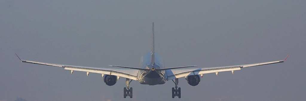
Precision Approaches
|
|
|
- Geraldine Ford
- 5 years ago
- Views:
Transcription
1 Precision Approaches
2 The purpose of an IFR approach

3 Precision approaches Non-Precision Approaches An approach where you have means of measuring deviation of the desired vertical profile, is a precision approach. Example : ILS

4 Precision approaches Non-Precision Approaches Any other approach is a non-precision approach. Examples : VOR approach, NDB approach, LOC (G/S out) approach
5 Instrument Visual Fly an approach based on instruments Transition to visual segment for landing Straight-in Position the aircraft for landing Circle-to-land
 Visibility good")
6 Instrument Visual To see the Runway : Ceiling high enough (out of clouds) Visibility good enough
7 Obstacle Clearance How low can you go?

8 Precision Approach Minima During a precision approach, you follow the descent profile until you reach the Decision Altitude or DA. This is where you decide to continue or go- around. The DA can be an altitude Above Mean Sea Level, AMSL, based on the QNH and read on the BARO altimeter, or a Radio Altitude or RA, read on the Radio Altimeter, indicating your actual altitude above the ground, depending on the procedure flown.
9 Non-Precision Approach Minima During a non-precision approach, the lowest altitude you can safely descend to is called the Minimum Descent Altitude or MDA. You can fly level at the MDA until reaching your Missed Approach Point or MAPt. This is where you decide to continue or go-around. MDA will be an altitude Above Mean Sea Level or AMSL. Based upon the QNH and read on the BARO altimeter.
10 Approach Minima If you don t see the RWY at the minima : GO-Around! (decision altitude ) Are used to determine whether you can fly an approach Tell you how low you can safely go without seeing the RWY Assure go-around obstacle clearance, even in the event of a missed approach with engine failure
11 Approach Minima Are published for every approach, considering visibility, obstacle clearance and aircraft performance limitations. Are found on the approach charts Are different for every approach and may vary depending the current conditions. These can be: Aircraft equipment and Type (Category) Airport equipment and/or local procedures Aircrew qualification
12 Aircraft Category Every aircraft type has one of the following approach categories based on average approach speed : Category A : Speed < 91 kts. (eg. C172, PA28,...) Category B : Speed 91 kts < 121 kts. (eg. King Air) Category C : Speed 121 kts < 141 kts. (eg. B737, A320,...) Category D : Speed 141 kts < 166 kts. (eg. B747, A340,...) Category E : Speed >166 kts. (eg. Concorde) As a pilot, you should know under which category your aircraft type is classified.
13 Example : Straight-in MDA for this approach is 720ft MSL for all aircraft categories. For B737 (Cat C) you require at least 1800m of RVR.
14 For a straight-in CAT I ILS, the DA will be 819ft MSL. Minimum RVR is 600m. With the Approach Lighting System (ALS) out, you require RVR of 1000m.
15 Precision Approach Minima ILS CAT I ( CAT I ILS is the default ILS approach ) RVR 550m DA 200ft AAL ( Above Aerodrome Level (above the landing threshold)) CAT II RVR 350m DH 100ft RA CAT III RVR 200m DH 50ft RA» CAT IIIa (guidance until touchdown)» CAT IIIb (guidance during roll-out)» CAT IIIc (guidance until taxi-in to the gate) Most commercial aircraft and airlines are CATIIIa Low Visibility Procedures (LVP) must be in force to conduct CATII or CATIII approaches. LVP are put in force by local ATC. This comprises a different set of general rules for operations. However, practice CATII-III apporaches may be performed by aircrew when LVP not in force. In that case ATC must be advised. They will then shed responsibility by stating equipment reliability is not guaranteed.
16 Meteorological conditions Approach Ban procedure : An approach may be commenced regardless of the weather conditions at the time, however To continue past the Outer Marker or equivalent position, the reported visibility must be equal or better than those required on the approach chart for the current conditions. Only the visibility is required to fly an approach beyond the Outer Marker or equivalent. Once past the OM or equivalent position, the approach may be continued down to DA/MDA regardless of weather reports received. For circle-to-land approaches you must have the ceiling and the visibility at or above minima to continue past the outer marker or equivalent.
17 Meteorological conditions Visibility RVR : Visibility : The visibility is reported by a certified observer at a certain observatory. This is usually the TWR. They can estimate the visibility according to known landmarks in view. (eg. Buildings, hilltops, towns, etc ) RVR : Runway Visual Range This is an electronically measured visibility by transmissiometers along the runway. It is specialised equipment that is not installed at all airports. You can check the 10-9 charts to see is it is available. RVR will be reported in METAR, ATIS and on TWR frequency. Example : R25L/P1500N R27/0600U : RVR Rwy25L = more than 1500m, tendency No change : RVR Rwy27 = 600m, tendency Up R32/0350D : RVR Rwy32 = 350m, tendency Down Under the same conditions, RVR is generally higher than VIS. Therefore, RVR will sometimes allow pilots to fly approaches when the VIS is below the minima.
18 EBCI 22006KT 0800 FG OVC001 13/12 Q1026 NOSIG Can you fly the straight-in ILS? Can you fly it when Approach Lighting System is out? EBCI 19002KT 3000 OVC008 BKN040 13/12 Q1026 NOSIG Can you fly the circle to land in B737? Can you fly the circle to land in B747? EBCI 21009KT 4500 BR SCT004 13/12 Q1026 NOSIG Can you fly the Circle to land? Yes, you need the VIS, not the ceiling. No, in this case the RVR required is 1000m Yes, OVC008 = 800ft above airfield. 800ft + 600ft elev = 1400ft. No, Ceiling requirements are OK, but now you need 3600m of VIS. Yes, SCT clouds are not considered to be a ceiling. You can try the APP, but Captain will be aware of posibility to lose the RWY during circling procedure...

19
20 Prepare the FMC by selecting Vref F30 or F40 in the Approach Ref page. In the DEP/ARR page, select the arrival and approach you expect.
21 Put these switches in ADF1 and VOR2 to show them in the ND bottom corners. Destination field EBCI in FIX page. Then type /10 in L2 for a green 10nm ring around the airfield. (Good idea but absolutely not necessary...) Select Locator-Outer Marker (LOM) in ADF1 if there is one installed on the ILS. NAV1, ILS freq, NAV2, VOR on the field or any other VOR that may be useful.
22 Prepare BARO minima 819ft. Prepare QNH 1024 in the baro.
23 Arm the Speed Brakes. According to normal According to normal procedures these are Armed when the Landing Gear comes down, but there is no harm in arming them sooner. Prepare Autobrake Setting. OFF, 1, 2, 3 or MAX. Depending on the Runway length, conditions and company policy.
24 You can extend the centreline by selecting the Final Approach Point (FAP) on top and entering the inbound course of the ILS ins INTC CRS before pushing EXEC. ( Again : recommended, NOT necessary )
25 Arm APP, reduce to UP speed. Once ATC turns you on the intercept Hdg and clears you for the approach, you Arm APP. Notice VOR/LOC and G/S appear armed in the FMA. Also reduce Speed window to green UP speed on the Speed-Tape, to be ready for Flap extension.
26 Set RWY Hdg VOR/LOC captures and the airplane turns onto the Localizer. Now set your Hdg bug to the RWY hdg. Notice that the A/P has switched to Single CH.
27 Flaps 1, match speed. At 10nm out (see NAV2 DME or green ring) it is the latest time to start configuring the aircraft for landing. Select Flaps 1 and match the speed to 1-speed.
28 Flaps 5, match speed. The B737 hardly decellerates on the Glide- Slope if you don t have at least Flaps 5 out. It is a good idea to have F5 by Glide-Slope intercept. However, depending on Aircraft Weight and wind conditions, you may choose to delay flap extension to improve Low-Drag performance.
29 Set Missed approach Altitude As the Glide-Slope captures, it is a good time to set Missed Approach altitude.
30 Gear Down, F15, match speed Speed brakes armed Ldg Checklist to the flaps. At the Outer Marker, +/- 4nm out or at the latest 3.5nm out, select Gear Down, Flaps15, arm the Speed Brakes. Call for the Landing Checklist to the flaps Sometimes the airplane may be difficult to slow down. (descending on the G/S with F5) In this case selecting Flaps10 may help. If all else fails, selecting Gear Down sooner, (before reaching the OM) will usually solve your energy problem.
31 F25, match speed. Now slow down further to Minimum Approach Speed, gradually extending landing flaps. With landing Flaps30, you can select F30 straight away after F15. With landning flaps40, first select F25, match speed, and as the airplane slows down below 162kts, select F40. (observe Flap placard speeds...)
32 F30-F40, match speed, Ldg Checklist Observing the Flap placard speeds, select landing flaps and Fly-speed. (= Vref +wind correction) (minimum 5kts) Call for Landing checklist
33 The CAT I minima are represented by this green bug on the altitude tape. Landing Checklist completed, cleared to land. 200ft above the minimums, 420ft above the ground you still see nothing... Continue to look insideoutside.
34
35 Minima : Runway in sight! Now you can disconnect the A/P and A/T and land manually... You can also choose to keep the A/P and A/T in a little longer until the minimum use height MUH =158ft RA. Below this you MUST disconnect and land manually!
36 You could have landed, but ATC instructs you to Go- Around... The G/A call is : Go-around, Flaps 15!
37 Go-around, Flaps 15! -Push TO/GA button and select Flaps 15. -The A/P will kick out, so you will have to fly the Go-around manually! -To do this follow the F/D bars, they will tell you to pull the nose up to
38 Positive Rate, Gear UP 400ft, LNAV, F5 - Once you see a positive rate of climb on 2 instruments, (Altitude tape AND V/S) select Gear UP. - When passing 400ft RA, select LNAV. - This is also the earliest time to start accelerating. To do this select Flaps 5. - Pitch for Speed meaning that the speed is controlled by lowering or pulling the nose up. - After passing 1000ft RA you can re-engage the A/P.
39 LNAV is engaged, T/O power is set, the Gear is up and the Flaps are to 5. You are now in the same situation as a normal Take- Off...
40 The A/T has remained engaged all the time and speed-pitch commands were a function of flaps setting. Once ALT-ACQ engages to intercept the G/A altitude, the Speed window opens up and allows the pilot to adjust the target speed. To accelerate : select BUG UP (to green UP speed) on the speed tape and retract the flaps on schedule.
41 After T/O checklist... Flaps UP, Speed UP, Gear UP, level at 3000ft, LNAV and A/P engaged... Go-around completed! The A/P will now even fly your lateral track for the G/A procedure as it was programmed in te FMC by selecting ILS25 Approach.

42
43 CAT III Autoland Dual Channel Differences : 2 autopilots will fly the approach, crosschecking eachother... Autoland FLARE capability provided by dual A/P effort. Minima are read on the RADIO altimeter, not the BARO altimeter like in the CAT I case. Go-around will be fully automatic!
44 This is the chart for CAT II ILS Rwy25L in Brussels. Notice that you will never find a CAT III chart. The reason for this is that CAT III minima are always 50ft-RVR200m. The CAT II minima are published The CAT II minima are published here. They are different for every approach, because they depend upon the terrain just before the runway. Notice that RA is clearly stated, meaning that the minima are to be read on the Radio Altimeter ONLY. ( DA(H) 259 is for information purposes only...)
45 CAT I minima are 200ft above the Rwy threshold. They are based on the QNH and expressed in altitude Above Mean Sea Level (AMSL). They are read out on the BARO altimeter. (Altitude Tape) CAT III minima are 50ft above the Rwy threshold. Because at this point, the airplane IS above the threshold, the minima will be 50ft RA EXACTLY. This is why there are never any CAT III minima published. CAT III minima are 50ft read out on the Radio Altimeter (RA). CAT II minima are exactly 100ft above te Rwy threshold, but as the airplane is not yet above the Rwy, the RA read-out will not be 100ft RA exactly. It will be dependant upon the terrain just before the Rwy. This is why there are minima published on the CAT II chart. CAT II minima are read out on the Radio Altimeter (RA).


46 Set minima selector bug to RADIO and set 50ft RA. The ILS freq is selected on both NAV1 and NAV2. The LOM can still be selected on ADF1 for reference. The rest of the preparations are the same as for a CAT I ILS approach. For CAT III operations, F40 landing is recommended as the lower pitch attitude will improve pilots view outside the cockpit.

47 Arm APP, second A/P in CMD. You should try to arrive on intercept heading with Flaps 5 and speed matched for F5. When ATC clears you for the approach, arm the APP mode and engage second A/P in command.
48 Set RWY Hdg VOR/LOC captures and the airplane turns onto the Localizer. Now set your Hdg bug to the RWY hdg. Notice that the A/P has switched to Single CH. The second A/P will engage at 1500ft RA. The latest point where second A/P can be engaged for dual channel performance = 800ft RA.

49 Gear Down, F15, match speed Speed brakes armed Ldg Checklist to the flaps. Glide Slope alive : Gear Down, Flaps 15, match speed, Speed brakes armed. Call for Landing Checklist to the Flaps
50 Flaps 25, match speed. At 1 dot below the Glide : Flaps 25, match speed.
51 F40, match speed, Ldg Checklist Set Missed Approach altitude G/S captures : Flaps 40, match speed Complete Landing Checklist Set Missed Approach altitude
52
53 Go-around, Flaps 15! The CAT II and CAT III minima are read out on the Radio Altimeter in the top right corner of the PFD. At 50ft RA, FLARE mode should engage and perform the autoland. If not, the Captain must be ready to disconnect and land manually if this does not happen. Push TO/GA Select Flaps 15 The Autopilots will fly the Go-Around automatically!
54 Positive Rate, Gear UP! - Once you see a positive rate of climb on 2 instruments, (Altitude tape AND V/S) select Gear UP.
55 LNAV, Flaps 5 - When passing 400ft RA, select LNAV. - This is also the earliest time to start accelerating. To do this select Flaps 5.
56 Bug UP... Once ALT-ACQ engages to intercept the G/A altitude, the last engaged A/P trips out, the Speed window opens up and allows the pilot to adjust the target speed. Select the speed bug to the green UP speed and retract the flaps on speed schedule.
57 Flaps UP, Speed UP, Gear UP, level at 2500ft, LNAV and A/P engaged... Once you are established on the radial-266 to FLO you can climb to 4500ft by setting it in the ALT window and pushing LVL CHG. Go-around completed!

58
59
60
61
62 Remarks : Configuration differences : You will have noticed a difference in configuration techniques between CAT I and CAT III dual channel profiles. During a CAT I ILS, the standard is to use low drag techniques, meaning that you will delay flap and gear extension to optimise performance and noise characteristics. When performing a CAT III dual channel approach, earlier configuration is necessary to guarantee a stabilised approach. CAT II approaches : When would you do a CAT II approach? This can be a good option if for example the airport or aircraft equipment is downgraded to CAT II operations only.
63
SOFTWARE. Control of the AMS SYSTEM CONTROL AND MONITORING OF AIRFIELD GROUND LIGHTING EQUIPMENT
 Control of the AMS SYSTEM SOFTWARE CONTROL AND MONITORING OF AIRFIELD GROUND LIGHTING EQUIPMENT Description of function airfield ground lighting equipment are shown on the screen representing the airport
NORMAL TAKEOFF. Maintain takeoff flaps for close in turn: V2 - max bank angle 15 V up to 30 (airspeed bug).
.") TAKEOFF ALTERNATE: If departure weather is below landing minimums (CAT I) you need a takeoff alternate within one hour (still air - 390 nm). Takeoff alternate must meet same weather minimums as regular
TAKEOFF ALTERNATE: If departure weather is below landing minimums (CAT I) you need a takeoff alternate within one hour (still air - 390 nm). Takeoff alternate must meet same weather minimums as regular
USE ALTIMETER SETTING
 USE ALTIMETER SETTING 1. Introduction One of the main instruments of the aircraft is the altimeter. The altimeter must be tuned to the right pressure in order to have the right value displayed and to be
AVIATION INVESTIGATION REPORT A04A0057 WING SCRAPE DURING A REJECTED LANDING
 AVIATION INVESTIGATION REPORT A04A0057 WING SCRAPE DURING A REJECTED LANDING CARGOJET AIRWAYS LIMITED BOEING 727-225 C-GCJB GREATER MONCTON INTERNATIONAL AIRPORT MONCTON, NEW BRUNSWICK 28 MAY 2004 The
FLIGHT INSTRUMENTS. This manual is dedicated only for IVAO Network activities. This document must not be used in real aviation or in others networks.
 FLIGHT INSTRUMENTS 1. Introduction The flight instruments are the instruments in the cockpit of an aircraft that provide the pilot with flight parameters. The flight instruments are used in conditions
July 13, 2017 Session #1 In Lieu of the Surface Observation Including EWINS Authority, RTMA, Web Cams, and Remote Observation Systems
 July 13, 2017 Session #1 In Lieu of the Surface Observation Including EWINS Authority, RTMA, Web Cams, and Remote Observation Systems Part 121 Operator Perspective: Equivalent Level of Safety Using Remote
To teach the instrument student knowledge of the elements related to an instrument takeoff and the primary instruments for pitch, bank, and power.
 INSTRMENT TAKEOFF (1.1..) OBJECTIVE To teach the instrument student knowledge of the elements related to an instrument takeoff and the primary instruments for pitch, bank, and power. COMPLETION STANDARDS
M o d u l e k A i r c r a f t A e r o d y n a m i c s, S t r u c t u r e s a n d S y s t e m s
 Category A B1 B2 B3 08 Instrument systems (ATA 31) Level 1 2 3 M o d u l e 1 3-0 8 k A i r c r a f t A e r o d y n a m i c s, S t r u c t u r e s a n d S y s t e m s I n s t r u m e n t S y s t e m s -
QNH: With this setting set on your altimeter you will be reading altitude above mean sea level based on the local station pressure.
 ALTIMETRY How many different altimeter settings confront you when operating internationally? Not only that, how many different ways are there to report an altimeter setting? If not operating internationally
Section 7: Hazard Avoidance
 7.1 In-Flight Hazard Awareness Section 7: Hazard Avoidance As technology improves, pilots have more and more real-time information within reach in all phases of flight. Terrain proximity, real-time weather
JAA Administrative & Guidance Material Section Five: Licensing, Part Two: Procedures
 Introduction: 1 - To fully appreciate and understand subject 032 Performance (Aeroplanes), the applicant will benefit from background knowledge in Subject 081 Principles of Flight (Aeroplanes). 2 For JAR-FCL
Flight Operations Briefing Notes
 I Introduction Operators with international routes are exposed to different standards in terms of: Altitude measurement, using different units (i.e., feet or meters); Altitude reference setting (i.e.,
JeppView for Windows. General Information. Runway Information. Communication Information. jep=jeppesen
 Airport Information For UWOO Printed on 27 Jan 208 Page (c) SANDERSON, INC., 208, ALL RIGHTS RESERVED jep= JeppView for Windows General Information Location: RUS ICAO/IATA: UWOO / REN Lat/Long: N5 47.75',
ALTERNATES FUEL REQUIREMENTS
 737 Pilot Gouge 15 Jan 13 pg.1 CAUTION! This gouge is a compilation of information that is NOT endorsed by anyone. The material may be out of date or incorrect. If there is any discrepancy, the Flight
Pilot briefing ENTC - Tromsø airport, Langnes
 Pilot briefing ENTC - Tromsø airport, Langnes NOTE: The content in this briefing will not be updated as frequently as AIP Norway. Make sure you always check relevant information in the latest edition of
Skyhawk CHECKLIST 172 MODEL V - SPEEDS
 Skyhawk CHECKLIST V - SPEEDS Vso 44 Stall Speed in Landing Configuration Vs 50 Stall Speed in Clean Configuration Vr 54 Takeoff Rotation Speed Vx 59 Best Angle of Climb Vy 73 Best Rate of Climb Vfe 85
AGENCE POUR LA SÉCURITÉ DE LA NAVIGATION AÉRIENNE EN AFRIQUE ET A MADAGASCAR. Mise en vigueur/effective date VALIDITE/Validity :
 AGENCE POUR LA SÉCURITÉ DE LA NAVIGATION AÉRIENNE EN AFRIQUE ET A MADAGASCAR AIRAC AIP SUP Phone +(242) 05 377 95 54 +(242) 05 377 95 64 Fax +(242) 05 377 95 44 AFTN FCCCYNYX email congobni@asecna.org
HEIGHT ALTITUDE FLIGHT LEVEL
 HEIGHT ALTITUDE FLIGHT LEVEL 1. Definition There are several ways to indicate the vertical position of aircraft and/or obstacles; each has another meaning and is used in a particular situation: 2. Units
Airbus A320 registered TS-IMC Date and time 12 March 2013 at 10 h 15 UTC (1) Operator
 Operator") www.bea.aero REPORT INCIDENT Runway overrun during taxiing after landing (1) Except where otherwise stated, the times shown in this report are expressed in Universal Time Coordinated (UTC). Aircraft Airbus
www.bea.aero REPORT INCIDENT Runway overrun during taxiing after landing (1) Except where otherwise stated, the times shown in this report are expressed in Universal Time Coordinated (UTC). Aircraft Airbus
Which instrument will become inoperative if the pitot tube becomes clogged?
 Gleim FAA Test Prep: Private Pilot (12 questions) Study Unit 2a [Airplane Instruments, Engines, and Systems] Name: Date: [1] Gleim #: 2.3.23 -- Source: PHAK Chap 7 (Refer to Figure 4.) Which color identifies
SERIOUS INCIDENT. Aircraft Type and Registration: 2) Embraer EMB 121 Xingu F-TEZZ. Date & Time (UTC): 1 June 2010 at 1000 hrs.
 Embraer EMB 121 Xingu F-TEZZ. Date & Time (UTC): 1 June 2010 at 1000 hrs.") SERIOUS INCIDENT Aircraft Type and Registration: Date & Time (UTC): Location: Type of Flight: 1) Embraer ERJ 190-200 LR G-FBEE, 2) Embraer EMB 121 Xingu F-TEZZ 1 June 2010 at 1000 hrs Jersey Airport, Channel
SERIOUS INCIDENT Aircraft Type and Registration: Date & Time (UTC): Location: Type of Flight: 1) Embraer ERJ 190-200 LR G-FBEE, 2) Embraer EMB 121 Xingu F-TEZZ 1 June 2010 at 1000 hrs Jersey Airport, Channel
NAVIGATION (1) GENERAL NAVIGATION
 GENERAL NAVIGATION") 1 Which is the highest latitude listed below at which the sun will rise above the horizon and set every day? A 68 B 66 C 62 D 72 2 An aircraft flies a great circle track from 56 N 070 W to 62 N 110 E.
1 Which is the highest latitude listed below at which the sun will rise above the horizon and set every day? A 68 B 66 C 62 D 72 2 An aircraft flies a great circle track from 56 N 070 W to 62 N 110 E.
SA A NATIONAL TRANSPORTATION SAFETY BOARD. Airplane Performance Study Korean Air Flight 801 DCA97MA058. Docket No. Exhibit No. WASHINGTON, D.C.
 Docket No. Exhibit No. SA-517 13A NATIONAL TRANSPORTATION SAFETY BOARD WASHINGTON, D.C. Airplane Performance Study Korean Air Flight 801 DCA97MA058 Guam August 6, 1997 National Transportation Safety Board
Example of Aircraft Climb and Maneuvering Performance. Dr. Antonio A. Trani Professor
 Example of Aircraft Climb and Maneuvering Performance CEE 5614 Analysis of Air Transportation Systems Dr. Antonio A. Trani Professor Example - Aircraft Climb Performance Aircraft maneuvering performance
21 Flight checklists Mission 1: Delta-glider to ISS
 21 Flight checklists This section contains point-by-point checklists for some complete flights. While flying these checklists, you may want to save regularly ( ), so you can pick up from a previous state
Atmospheric Pressure. Pressure Altimeter. Pressure Altimeter
 Atmospheric Pressure The : An instrument to measure altitude based on an aneroid barometer. It can be adjusted for changes in atmospheric pressure 1 2 Altimeter Setting Is not SLP, but close to it. If
Upplýsingabréf Þjálfunar- og skírteinadeildar nr. 2/2015. CB-IR and EIR Conversion Oral Examination Guidance Material
 Upplýsingabréf Þjálfunar- og skírteinadeildar nr. 2/2015 Dags: 03.07.2015 CB-IR and EIR Conversion This document contains a list of learning objectives in the subjects Air Law, Flight Planning & Monitoring,
AERODROME METEOROLOGICAL OBSERVATION AND FORECAST STUDY GROUP (AMOFSG)
") AMOFSG/10-IP/4 21/5/13 AERODROME METEOROLOGICAL OBSERVATION AND FORECAST STUDY GROUP (AMOFSG) TENTH MEETING Montréal, 17 to 19 June 2013 Agenda Item 5: Aerodrome observations AUTOMATED CLOUD INFORMATION
AMOFSG/10-IP/4 21/5/13 AERODROME METEOROLOGICAL OBSERVATION AND FORECAST STUDY GROUP (AMOFSG) TENTH MEETING Montréal, 17 to 19 June 2013 Agenda Item 5: Aerodrome observations AUTOMATED CLOUD INFORMATION
Civil Air Patrol Auxiliary of the United States Air Force
 Mountain Flying Qualification Course Civil Air Patrol Auxiliary of the United States Air Force Mountain Searching ELT Searches Conduct search at highest practical altitude to increase chance of detecting
Visual Tutorial. Pitot Static System Simulator. Adobe (formerly Macromedia) Flash Requirements
 Flash Requirements") Visual Tutorial Tutorial Version 1.01 Pitot Static System Simulator Adobe (formerly Macromedia) Flash Requirements Thank you for using the Pitot Static System Simulator from luizmonteiro.com. Please note
Visual Tutorial Tutorial Version 1.01 Pitot Static System Simulator Adobe (formerly Macromedia) Flash Requirements Thank you for using the Pitot Static System Simulator from luizmonteiro.com. Please note
Preventing Runway Excursions. Landing on wet / Contaminated Runways
 Preventing Runway Excursions Landing on wet / Contaminated Runways Overview Introduction Definition Runway Condition Runway Condition Reporting Pilot Operational Aspects Landing Performance Airport Operational
Preventing Runway Excursions. Landing on wet / Contaminated Runways
 Preventing Runway Excursions Landing on wet / Contaminated Runways Overview Introduction Definition Runway Condition Runway Condition Reporting Pilot Operational Aspects Landing Performance Airport Operational
Learning. Goals. of pressure. aircraft. Altimeter knob. Page 1 of 8. Document : V1.1
 LEVELS AND ALTITUDES Learning Goals LEVELS AND ALTITUDES In aviation it is of the utmost importance that a pilot knows his height above ground level for safe landing and obstacle avoidance. For air traffic
Airplane Instruments 1.1 COMPASS ERRORS compass deviation. acceleration/deceleration error compass turning error
 Airplane Instruments 1.1 COMPASS ERRORS 1. During taxi, you should check your compass to see that it is swinging freely and indicating known headings. 2. The difference between direction indicated by a
Flight Operations Briefing Notes
 Flight Operations Briefing Notes I Introduction Flight crew awareness and alertness are key factors in the successful application of windshear avoidance and escape / recovery techniques. This Flight Operations
FLIGHT INSTRUMENTS TYPICAL QUESTIONS
 FLIGHT INSTRUMENTS TYPICAL QUESTIONS JANUARY 2004 TYPICAL QUESTIONS FLIGHT INSTRUMENTS PAGE 1 of 76 1. If the pitot Head and Static Vent were blocked by ice, the instruments that would be affected are:
The Informed Scheduler
 The Informed Scheduler Thursday, January 21, 2016 1:00 p.m. 2:30 p.m. PRESENTED BY: Vinton Brown, Flight Safety International James M. Kohler, Chief Pilot, DuPont Andrew M. Bourland, CAM, Chief Pilot,
Airport Information. Details for SUPRUNIVKA. State/Province
 Airport Information Details for City POLTAVA State/Province Country UKR Latitude N 49 34' 0.00" Longitude E 34 23' 39.00" Elevation 505 Longest Runway 8300 Magnetic Variance E 7.0 Fuel Type No fuel is
Learning. Goals. Page 1 of 6. Document : V1.1
 Learning Goals Lights configurations Airplane Page 1 of 6 Page 2 of 6 The external lights on aircraft fall into two general categories. The first is navigation lights or beacons thatt are always illuminated
Effective: SPECI ALERTING
 AUSTRALIA AERONAUTICAL INFORMATION SERVICE AIRSERVICES AUSTRALIA GPO BOX 367, CANBERRA ACT 2601 Phone: 02 6268 4874 Email: aim.editorial@airservicesaustralia.com Effective: AERONAUTICAL INFORMATION CIRCULAR
Also published by the Board of Trade, United Kingdom as C.A.P. 268
 Extracted from ICAO Circular 88-AN/74, pp 142-149. 2014 PicMA site editor's note: this flight was initially conducted under BEA's policy to use PicMA procedures. However the Captain elected to abandon
AIR TRAFFIC INCIDENT REPORT FORM
 Address: Rannsóknarnefnd samgönguslysa Flugvallarvegur 7, 101 Reykjavik, Iceland Telephone: +354 511 6500 Telefax: +354 511 6501 E-mail: RNSA@RNSA.is AIR TRAFFIC INCIDENT REPORT FORM For use when submitting
Gleim Private Pilot FAA Knowledge Test 2015 Edition, 1st Printing Updates July 2015
 Page 1 of 6 Gleim Private Pilot FAA Knowledge Test 2015 Edition, 1st Printing Updates July 2015 NOTE: Deleted text is displayed with a line through it. New text is shown with a blue background. If you
AERODROMES PANEL (AP) VISUAL AIDS WORKING GROUP (VAWG) FIFTH MEETING. Montréal, Canada, 25 to 27 June 2008
 VISUAL AIDS WORKING GROUP (VAWG) FIFTH MEETING. Montréal, Canada, 25 to 27 June 2008") VAWG/5-DP/18 25/6/08 AERODROMES PANEL (AP) VISUAL AIDS WORKING GROUP (VAWG) FIFTH MEETING Montréal, Canada, 25 to 27 June 2008 Agenda Item 11: Any other business NEW TECHNOLOGIES FOR HIGH PRECISION PAPI
VAWG/5-DP/18 25/6/08 AERODROMES PANEL (AP) VISUAL AIDS WORKING GROUP (VAWG) FIFTH MEETING Montréal, Canada, 25 to 27 June 2008 Agenda Item 11: Any other business NEW TECHNOLOGIES FOR HIGH PRECISION PAPI
METEOROLOGY PANEL (METP) WORKING GROUP- METEOROLOGICAL OPERATION GROUP (MOG) FIRST MEETING
 WORKING GROUP- METEOROLOGICAL OPERATION GROUP (MOG) FIRST MEETING") 8 28/7/15 METEOROLOGY PANEL (METP) WORKING GROUP- METEOROLOGICAL OPERATION GROUP (MOG) FIRST MEETING Gatwick, United Kingdom, 08 to 11 September 2015 Agenda Item 3: Matters relating to SADIS 3.3: Operations
8 28/7/15 METEOROLOGY PANEL (METP) WORKING GROUP- METEOROLOGICAL OPERATION GROUP (MOG) FIRST MEETING Gatwick, United Kingdom, 08 to 11 September 2015 Agenda Item 3: Matters relating to SADIS 3.3: Operations
Aircraft Operation Anomaly Detection Using FDR Data
 Aircraft Operation Anomaly Detection Using FDR Data Lishuai Li, Maxime Gariel, R. John Hansman IAB/Airline Industry Consortium Nov 4, 2010 1 Motivation Commercial aircraft accident rate has dropped significantly.
National Transportation Safety Board Aviation Accident Final Report
 National Transportation Safety Board Aviation Accident Final Report Location: Elk City, OK Accident Number: Date & Time: 02/03/2014, 2300 CST Registration: N61YP Aircraft: CESSNA 525 Aircraft Damage: Substantial
Off-Airport Landings
 Off-Airport Landings Thanks to Tim Wells for developing this presentation and making it available to the soaring community Additional photos by Wally Berry, 2018 Waverly Hall Chilhowee Chilhowee (same
TAKEOFF CONSIDERATIONS...
 CHAPTER 4 TAKEOFFS TAKEOFF CONSIDERATIONS.................. 2-37 AIRSPEED.................................. 2-37 TAKEOFF POWER............................ 2-38 RUNWAY LENGTH REQUIREMENT.............. 2-39
AIP AMENDMENT SWEDEN
 AIP AMENDMENT SWEDEN AIP AIRAC AMDT 3 26 APR 2018 EFFECTIVE 24 MAY 2018 LFV, SE-601 79 NORRKÖPING. Phone +46 11 19 20 00. Fax +46 11 19 25 75. AFTN ESKLYAYT CORRIGENDUM TO AIP AIRAC AMDT 3/2018 In the
Vaisala AviMet Automated Weather Observing System
 Vaisala AviMet Automated Weather Observing System Solutions to meet your challenges Our mission: to help you operate succesfully Safe, economical, reliable and flexible operation of your airport is ensured
ADL110B ADL120 ADL130 ADL140 How to use radar and strike images. Version
 ADL110B ADL120 ADL130 ADL140 How to use radar and strike images Version 1.00 22.08.2016 How to use radar and strike images 1 / 12 Revision 1.00-22.08.2016 WARNING: Like any information of the ADL in flight
Transparency: Redoubt ash cloud
 Module 1 Investigation 3 Transparency: Redoubt ash cloud Aerial view of Redoubt Volcano during a continuous, low-level eruption of steam and ash December 18, 1989 Source: photo by W. White, USGS, http://www.avo.alaska.edu/avo3/volc/redou/photo.htm
MK V and MK VII Enhanced Ground Proximity Warning System Pilot's Guide Rev. D - March 2000 MK V & MK VII EGPWS Pilot Guide 1
 MK V and MK VII Enhanced Ground Proximity Warning System Pilot's Guide MK V & MK VII EGPWS Pilot Guide 1 This document is an unpublished work Copyright 2001 Honeywell International Inc. All rights reserved
E230 Aircraft Systems
 E230 Aircraft Systems Fly high Fly low 6th Presentation School Of Engineering Air Pressure Characteristics Altimeter is an instrument that measures the height (altitude) of the aircraft above sea level.
JeppView for Windows. General Information. Runway Information. Communication Information. jep=jeppesen
 irport Information For UUO Printed on 27 Jan 208 Page (c) SNERSON, IN., 208, LL RIGHTS RESERVE jep= JeppView for Windows General Information Location: RUS IO/IT: UUO / EGO Lat/Long: N50 38.63', E036 35.40'
Introducing AOPA FlyQ EFB
 Hi, just a reminder that you're receiving this email because you activated AOPA FlyQ EFB. Don't forget to add FlyQEFBSupport@seattleavionics.com to your address book so we'll be sure to land in your inbox!
L-3 Avionics Systems SkyWatch Traffic Advisory System
 Cirrus Design Section 9 Pilot s Operating Handbook and FAA Approved Airplane Flight Manual Supplement for L-3 Avionics Systems SkyWatch Traffic Advisory System When the L-3 Avionics Systems SkyWatch 497
A novel machine learning model to predict abnormal Runway Occupancy Times and observe related precursors
 A novel machine learning model to predict abnormal Runway Occupancy Times and observe related precursors Seattle ATM R&D seminar Floris Herrema 27 th of June 2017 Overview Introduction and Objective Approach
DVA 777 Program. August 2005 Volume DVA 777 Program
 1 DVA 777 Program August 2005 Volume 1.9 DVA 777 Program While we have experienced a decent amount of growth in the program over the past two years, we are looking to promote more pilots from the Stage
LANDMARK TM. Class B TAWS
 LANDMARK TM Class B TAWS WAAS-GPS Accurate - 320 Mile Range - Easily Integrated Introducing the LandMark Model 8100 LandMark is the first stand-alone Class B TAWS to offer an optional WAAS-GPS sensor.
NJ SURVEYORS CONFERENCE
 NJ SURVEYORS CONFERENCE PART 107 Ground School TODAY S AGENDA Regulations National Airspace System Operations Weather Loading and Performance 1 REGULATIONS Remote Pilot Certifications and Privileges When
Incident on 25 May 2001 at Cayenne-Rochambeau Airport (French Guyana) to the Airbus A registered F-GLZC operated by Air France
 to the Airbus A registered F-GLZC operated by Air France") N ISBN : 978-2-11-098263-6 Report Incident on 25 May 2001 at Cayenne-Rochambeau Airport (French Guyana) to the Airbus A340-311 registered F-GLZC operated by Air France Bureau d Enquêtes et d Analyses pour
N ISBN : 978-2-11-098263-6 Report Incident on 25 May 2001 at Cayenne-Rochambeau Airport (French Guyana) to the Airbus A340-311 registered F-GLZC operated by Air France Bureau d Enquêtes et d Analyses pour
Localizer Hold Autopilot
 Localizer Hold Autopilot Prepared by A.Kaviyarasu Assistant Professor Department of Aerospace Engineering Madras Institute Of Technology Chromepet, Chennai Localizer hold autopilot is one of the important
COMPILED)QUESTIONS)FROM)JER S)RTPC)NOTES) )!! RT1) )2006)! 1. Definition!of!LWMO?!(Takeoffs!RVR<400m,!Landings!RVR<550m).) 2.
QUESTIONS)FROM)JER S)RTPC)NOTES) )!! RT1) )2006)! 1. Definition!of!LWMO?!(Takeoffs!RVR<400m,!Landings!RVR<550m).) 2.") COMPILED)QUESTIONS)FROM)JER S)RTPC)NOTES)200662013) RT1) )2006) 1. DefinitionofLWMO?(TakeoffsRVR
COMPILED)QUESTIONS)FROM)JER S)RTPC)NOTES)200662013) RT1) )2006) 1. DefinitionofLWMO?(TakeoffsRVR
Flight and Orbital Mechanics. Exams
 1 Flight and Orbital Mechanics Exams Exam AE2104-11: Flight and Orbital Mechanics (23 January 2013, 09.00 12.00) Please put your name, student number and ALL YOUR INITIALS on your work. Answer all questions
MINISTRY OF DEFENCE MILITARY AIRCRAFT ACCIDENT SUMMARY
 MINISTRY OF DEFENCE MILITARY AIRCRAFT ACCIDENT SUMMARY AIRCRAFT ACCIDENT TO ROYAL AIR FORCE TORNADO F3 ZG751 AIRCRAFT: RAF Tornado F3 ZG751 DATE: 25 August 2003 LOCATION: PARENT UNIT: CREW: INJURIES: CFB
Encounter with damaging hail, Boeing , TF-ARD
 Encounter with damaging hail, Boeing 757-225, TF-ARD Micro-summary: This Boeing 757-225 had a damaging encounter with hail in flight. Event Date: 2005-08-20 at 1210 UTC Investigative Body: Aircraft Accident
Post Flight Report. Other crew: Other Details
 Post Flight Report Prepared by Guy Gratton General Details Type: Dornier 228 ARSF Purpose of Sortie: Reg: D-CALM P1: Joseph Date: 16 April 2010 P2: Davies Airfield(s): Cranfield / Cranfield Other crew:
Theory of Flight Flight Instruments and Performance Factors References: FTGU pages 32-34, 39-45
 Theory of Flight 6.09 Flight Instruments and Performance Factors References: FTGU pages 32-34, 39-45 MTPs: 6.09 Flight Instruments and Performance Factors Pitot Static Instruments Asymmetric Thrust Precession
Methodology for the creation of meteorological datasets for Local Air Quality modelling at airports
 Methodology for the creation of meteorological datasets for Local Air Quality modelling at airports Nicolas DUCHENE, James SMITH (ENVISA) Ian FULLER (EUROCONTROL Experimental Centre) About ENVISA Noise
LAPL(A)/PPL(A) question bank FCL.215, FCL.120 Rev_1/2016 NAVIGATION 060
/PPL(A) question bank FCL.215, FCL.120 Rev_1/2016 NAVIGATION 060") NAVIGATION 060 1 1 What is the angle of inclination of the Earth's axis to its orbital plane? 66,5 23,5 33,5 90 2 The meridian passing through Greenwich is known as? Main Meridian. Great Meridian. Prime
NAVIGATION 060 1 1 What is the angle of inclination of the Earth's axis to its orbital plane? 66,5 23,5 33,5 90 2 The meridian passing through Greenwich is known as? Main Meridian. Great Meridian. Prime
Theory of Flight. Pitot Static Instruments Flight Instruments and Performance Factors. MTPs:
 Theory of Flight 6.09 Flight Instruments and Performance Factors References: FTGU pages 32-34, 39-45 6.09 Flight Instruments and Performance Factors MTPs: Pitot Static Instruments Asymmetric Thrust Precession
Human Factors Assessment of Runway Status Lights (RWSL) and Final Approach Runway Occupancy Signal (FAROS) Maria Picardi Kuffner
 and Final Approach Runway Occupancy Signal (FAROS) Maria Picardi Kuffner") Human Factors Assessment of Runway Status Lights (RWSL) and Final Approach Runway Occupancy Signal (FAROS) FAA Operational Evaluations at Dallas Ft. Worth and San Diego International Airports Maria Picardi
Human Factors Assessment of Runway Status Lights (RWSL) and Final Approach Runway Occupancy Signal (FAROS) FAA Operational Evaluations at Dallas Ft. Worth and San Diego International Airports Maria Picardi
AWOS. Automated Weather Observing Systems COASTAL
 AWOS Automated Weather Observing Systems COASTAL Environmental Systems Monitor Monitor Your Your World World Coastal s Experience & Expertise Since 1981, Coastal Environmental Systems, Inc. (Coastal) has
Prepared by. A.Kaviyarasu Assistant Professor Department of Aerospace Engineering Madras Institute Of Technology Chromepet, Chennai
 Prepared by A.Kaviyarasu Assistant Professor Department of Aerospace Engineering Madras Institute Of Technology Chromepet, Chennai 1 The vertical touch down velocity of aircraft onto the runway is determined
Investigation Report
 Bundesstelle für Flugunfalluntersuchung German Federal Bureau of Aircraft Accident Investigation Investigation Report Identification Type of Occurrence: Serious incident Date: 5 January 2009 Location:
AERODROME METEOROLOGICAL OBSERVATION AND FORECAST STUDY GROUP (AMOFSG)
") AMOFSG/10-SN No. 5 19/4/13 AERODROME METEOROLOGICAL OBSERVATION AND FORECAST STUDY GROUP (AMOFSG) TENTH MEETING Montréal, 17 to 19 June 2013 Agenda Item 5: Aerodrome observations REPORTING OF RUNWAY VISUAL
AMOFSG/10-SN No. 5 19/4/13 AERODROME METEOROLOGICAL OBSERVATION AND FORECAST STUDY GROUP (AMOFSG) TENTH MEETING Montréal, 17 to 19 June 2013 Agenda Item 5: Aerodrome observations REPORTING OF RUNWAY VISUAL
Cockpit Basics. What does a child's spinning top have to do with flying an airplane? More than you might imagine.
 Cockpit Basics Airplanes have evolved from relatively simple to incredibly complex machines. But remember: Whether you're flying a Cessna Skyhawk SP Model 172 or a Boeing 777 300, you're still flying an
Traffic and Weather. Soaring Safety Foundation. Tom Johnson CFIG
 Traffic and Weather Soaring Safety Foundation Tom Johnson CFIG Weather Contents Weather Gathering Sources Weather Acquisition Enroute Weather Analysis Weather Hazards Weather in the Landing Pattern Basic
GEN 3.5 METEOROLOGICAL SERVICES
 AIP GEN 3.5-1 GEN 3.5 METEOROLOGICAL SERVICES 1. RESPONSIBLE SERVICE The meteorological services for civil aviation at Jordan are provided by the Jordanian Meteorological Department. Postal Address: Director
2008 Annual C-FOQA Statistical Summary Report
 2008 Annual C-FOQA Statistical Summary Report 2008 Annual C-FOQA Statistical Summary Report **************************************************** Enclosed is a statistical summary of Flight Operations Quality
Inspection of. Aerodrome Lighting Federal Aviation 1. Administration
 Inspection of Aerodrome Lighting Presented to: ICAO/ FAA Aerodrome Certification Inspectors Workshop for the Caribbean Region By: Laurie Dragonas, FAA Lead Airport Certification/Safety Inspector Date:
WMO Aeronautical Meteorology Scientific Conference 2017
 Session 2 Integration, use cases, fitness for purpose and service delivery 2.2 Terminal Area and Impact-based forecast Data-driven influence model of weather condition in airport operational performance
AFM Supplement. Pages Description Of Revision. IR 6/21/04 All Initial Issue Allan Hamann
 RECORD OF REVISIONS Page 2 of 16 Rev Date Pages Affected Description Of Revision Approvals IR 6/21/04 All Initial Issue Allan Hamann A 7/16/04 7 8-12 B N/A 1 Added Clarification regarding Altitude Alert
Additional capacity with Machine Learning. ART meeting Bretigny Bob Graham & Floris Herrema
 Additional capacity with Machine Learning ART meeting Bretigny Bob Graham & Floris Herrema Runway Throughput Challenge 16 to 28 congested airports 1.5+ million flights not catered for 160+ million people
B KMD 550/850 Multi-Function Display Quick Reference For Software Version 01/14 or Later
 F N B KMD 550/850 Multi-Function Display Quick Reference For Software Version 01/14 or Later 12 1 11 2 3 4 10 13 9 6 5 7 1. Brightness Control 2. Data Card 3. Display 4. Available Functions Legend 5. On/Off
Introduction to Aerospace Engineering
 Introduction to Aerospace Engineering Lecture slides Challenge the future 1 Introduction Aerospace Engineering Flight Mechanics Dr. ir. Mark Voskuijl 15-12-2012 Delft University of Technology Challenge
NINTH MEETING DISPLAY IN ATS UNITS. (Presented SUMMARY
 AMOFSG/9-SN No. 26 12/8/11 AERODROME METEOROLOGICAL OBSERVATION AND FORECAST STUDY GROUP (AMOFSG) NINTH MEETING Montréal, 26 to 30 September 2011 Agenda Item 6: MET informationn to support ATM UPDATING
Work Package 1: Final Project Report Appendix E: The METAR data
 Work Package 1: Final Project Report Appendix E: The METAR data First Assessment of the operational Limitations, Benefits & Applicability for a List of package I AS applications FALBALA Project Drafted
AOG Add On Gauges FSWXR-2100 Users Manual Rev. 1.0 FSWXR Users Manual Rev. 1.0
 FSWXR 2100 Users Manual Rev. 1.0 Realistic simulation of the real Collins WXR2100 for Microsoft Flightsimulator 9 AOG FSWXR2100 Page 1 1. Introduction Weather is the one of uncontrollable factors in aviation.
Fin design mission. Team Members
 Fin design mission Team Members Mission: Your team will determine the best fin design for a model rocket. You will compare highest altitude, flight characteristics, and weathercocking. You will report
The SBAS Offshore Approach Procedure (SOAP)
") Safety Regulation Group CAA PAPER 2010/01 www.caa.co.uk Safety Regulation Group CAA Paper 2010/01 Civil Aviation Authority 2010 All rights reserved. Copies of this publication may be reproduced for personal
Safety Regulation Group CAA PAPER 2010/01 www.caa.co.uk Safety Regulation Group CAA Paper 2010/01 Civil Aviation Authority 2010 All rights reserved. Copies of this publication may be reproduced for personal
StolSpeed Vortex Generators on a Harmon Rocket II Flight Test Report
 StolSpeed Vortex Generators on a Harmon Rocket II Flight Test Report Vernon Little Version 1.1, November 29, 2016 Summary StolSpeed Vortex Generators were installed on a Harmon Rocket II (C-GVRL). Flight
FAA AIRFIELD LIGHTING STANDARDS UPDATE
 FAA AIRFIELD LIGHTING STANDARDS UPDATE Present to: IES ALC GOVERNMENT LIGHTING COMMITTEE WASHINGTON, DC May 7, 2015 Tom Mai FAA Airport Engineering Division (AAS-100) Agenda FAA Airfield Lighting Equipment
Flight Instruments: Clocks, Tops & Toys
 Page E1 Chapter Five Flight Instruments: Clocks, Tops & Toys 1. [E1/Figure 1] Label the six main flight instruments: 3. [E3/3/2] Atmospheric pressure with a gain in altitude. A. decreases B. increases
ANALYSIS OF AIRCRAFT LATERAL PATH TRACKING ACCURACY AND ITS IMPLICATIONS FOR SEPARATION STANDARDS
 ANALYSIS OF AIRCRAFT LATERAL PATH TRACKING ACCURACY AND ITS IMPLICATIONS FOR SEPARATION STANDARDS Michael Cramer, The MITRE Corporation, McLean, VA Laura Rodriguez, The MITRE Corporation, McLean, VA Abstract
AOPA. Mitigating Turbulence Impacts in Aviation Operations. General Aviation Perspective
 AOPA Mitigating Turbulence Impacts in Aviation Operations General Aviation Perspective Rune Duke Senior Director, Airspace & Air Traffic Services Aircraft Owners & Pilots Association AOPA Air Safety Institute
Metar And Taf Decoding
 Metar And Taf Decoding 1 / 6 2 / 6 3 / 6 Metar And Taf Decoding examples: kmem 230853z auto 18014g18kt 10sm clr 16/m02 a3008 rmk ao2 slp117 t01561022 tsno $ klax 161550z cor 11004kt 2 1/2sm hz bkn011 bkn015
GENERAL REQUIREMENTS FOR SHOREBASED AIRFIELD MARKING AND LIGHTING
 NAVAIR 51-50AAA-2 1 MAY 2003 CHANGE 3 1 NOVEMBER 2017 TITLE TECHNICAL MANUAL GENERAL REQUIREMENTS FOR SHOREBASED AIRFIELD MARKING AND LIGHTING DISTRIBUTION STATEMENT A. Approved for public release; distribution