WIDELY USED IN MANUFACTURING PLANTS
|
|
|
- Clemence Long
- 5 years ago
- Views:
Transcription
1 SINCE 1916 PRECISION MEASURING INSTRUMENTS MODEL 7 IS JAPANS DOMESTICALLY DIAL GAUGE WIDELY USED IN MANUFACTURING PLANTS TOKYO, JAPAN
2 Mission Statement Harmony and Progress The reliable PEACOCK brand is highly acclaimed as being representative of Japans DIAL GAUGES. The name originates from a haiku poem by Shiki Masaoka that goes, Fanning out its tail in the Spring breeze see-peacock! Founder Kiyonobu Ozaki had been interested in haiku since the upper grades of primary school, and he established this trademark for the brand inspired by the neat image Shikis poem invoked. Manufacturing fine products that resemble the subtle pattern on the tail of PEACOCK has enable the company to contribute to society.


3 ISO 9001 Certified OZAKI MFG. CO., LTD. We, OZAKI MFG. CO., LTD., received ISO 9001 certification in 1999 and now renewed 01 edition. We have been supplying high quality measuring instruments with reliable brand "PEACOCK" to our customers not only Japan but also overseas countries. Management System Certificate COPY Appendix ISO Certification for DIAL GAUGES, PIC TEST INDICATORS, CYLINDER GAUGES AND ITS APPLIED DIAL GAUGES. Contents Quick Chart Dial Gauges Lever Type Dial Indicators Cylinder Gauges Inch Scale Dial Indicators Gauge Testers Thickness Gauges Dial Caliper Gauges Applied Dial Gauges Stands Signal Indicators Digital Indicators Parts Drawings R Design and specifications are subject to change without notice for future improvement.


 6 Replaceable")
 64 Special Length")


4 INDEX R Precision Measuring Instruments General Catalog 0 Quick Chart Weight of our products 14 for Dial Gauge 1 for Lever Type Dial Indicator for Cylinder Gauge Dial Gauges One Revolution Dial Gauges "Z" Series - Standard Dial Gauges 0.001, 0.00mm type 4- Standard Dial Gauges mm type6-7 Long Travel Dial Gauges -9 Miniature Dial Gauges0 Back Plunger Dial Gauges 1 Replaceable Contact Points - Outer Dimensions6-7 Accessories -9 Outer Dial Plates Backs 40 Repair tools 41 Technical Data4-4 Marking Service 44 Lever Type Dial Indicators Without Change Lever "PCN" series Double Dial Face "W" series 47 One Revolution New Pic Test 4-49 Low Measuring Force "E" series 0 Anti-Magnetic & Non-Electrifying "U" series 1 Large Dial Face "D" series With Change Lever "PC" series With Ruby ball "R" series 4 With Dovetail Stem "DSV" series Accessories (Option) 6 Replaceable Contact Points 7 Outer Dimensions Applied Examples 9 Precautions for Handling 9 Without Stem "V" series 60 Right Angle Contact Point for Pic Test Cylinder Gauges Standard "CC" series 6 Special Length below grip "CC" type 6 Short size "S" series 6 Standard "CG" series (Blind hole type) 64 Special Length below grip "CG" type 64 Dimensions for Feelers and Washers for Cylinder Gauges 6 "R" series Cylinder Gauges 66-6 Inch Scale Dial Indicators Dial Gages 0.001" type Dial Gages " type 71 Metric Graduations mm 7 Pic Test Indicators 7-74 Dial Bore Gage Sets 7 Dial Thickness Gage 76 Gauge Testers Dial Gauge Tester 0 Cylinder Gauge Tester 1 Thickness Gauges Dial Thickness Gauge mm type4- Dial Thickness Gauge 0.001mm type 6 Dial Swift Gauge 6 Pearl Scale 7 Snap Calipers 7 Large type Dial Thickness Gauges Roller type Dial Thickness Gauge Dial Sheet Gauges 9 Dial Pipe Gauges 90 Dial Lens Gauge 90 Dial Thickness Gauge Special Order 91 Dial Upright Gauges 9 Constant Pressure Thickness Gauges "FFG" "FFA" "FFD" series 9-96


 14-1 Linear Gauges, mm range 16-17 Linear Gauges, 0mm")


5 7 Dial Caliper Gauges Outside "LA" series 9-1 Inside "LB" series - Applied examples 4 Applied Dial Gauges Dial Depth Gauges "T" series 6-7 Digital Depth Gauges "T" series -9 Dial Inside Gauges "U" series 1 Dial Hole Gauge 111 Digital Hole Gauge 111 Lever type Contact Point "XY" series 11 Angle Contact Point "XZ" series 11 Bench Center Digital Indicators Digital Gauges(Cordless type) 1-1 Digital Gauges (Integrated Display type) 14-1 Linear Gauges, mm range Linear Gauges, 0mm range 1-19 Linear Gauge Rectangular wave out put type 1-19 Linear Gauges 0, 0mm range Linear Gauges 0.1µm. 0.µm resolution 14 Digital Counters Compact type Digital Counter with High Resolution 146 Digital Counter with Judging Function 147 Digital Indicator Application Series Deep Hole Bore Gauges 1-1 Outer Dimensions 14 Technical Glossary Stands Dial Gauge Stands Magnetic Stands 11 Magnetic Holder Parts Drawings PCN PC series Dial Gauges Thickness Gauges Lens Gauge16-16 Cylinder Gauges Signal Indicators Signal Gauge 0.001,, 0.0mm type1 Signal Checker 1 Signal Box 14 Signal Gauge Set-Up 16 Connection Diagram 17 Example of Use 1
6 INDEX (Alphabetical) No. Description Page C CCT- CC-0 CC-01 CC-1 CC- CC- CC-C CC-4 CC- CC-6 CC-1S CC-S CC-S CC-CS CC-01R CC-1R CC-R CC-R CC-CR CG-01 CG-1 CG- CG- CG-C CG-4 CG- CG-6 CG-01R CG-1R CG-R CG-R CG-CR Cylinder Gauge Tester Cylinder Gauge Cylinder Gauge Cylinder Gauge Cylinder Gauge Cylinder Gauge Cylinder Gauge Cylinder Gauge Cylinder Gauge Cylinder Gauge Short size Cylinder Gauge Short size Cylinder Gauge Short size Cylinder Gauge Short size Cylinder Gauge Cylinder Gauge Cylinder Gauge Cylinder Gauge Cylinder Gauge Cylinder Gauge Cylinder Gauge (Blind Hole Type) Cylinder Gauge (Blind Hole Type) Cylinder Gauge (Blind Hole Type) Cylinder Gauge (Blind Hole Type) Cylinder Gauge (Blind Hole Type) Cylinder Gauge (Blind Hole Type) Cylinder Gauge (Blind Hole Type) Cylinder Gauge (Blind Hole Type) Cylinder Gauge Cylinder Gauge Cylinder Gauge Cylinder Gauge Cylinder Gauge C-00 C-700 C-7HS CM-B Digital Counter 14 Digital Counter 14 Digital Counter 146 Digital Counter 147 No. D DL- D- D-B D-UZ D- D-0 D-0 D-0 DN- DN-S DN-0 DN-0S DL-S D-S D-SB D-S D-SS D-HS D-0S D-0S D-0S DG-17 DG-0 DG-7 E EG-1 EG- EMCC- EMCC- EMCC-4 EMCC- EMCC-6 F FFA-1 Description Page No. Description Page No. Description Page Linear Gauge 16 Linear Gauge 16 Linear Gauge 1 Linear Gauge 16 Linear Gauge 1 Linear Gauge 1 Linear Gauge 140 Linear Gauge 140 Linear Gauge 1 Linear Gauge 1 Linear Gauge 1 Linear Gauge 1 Linear Gauge 16 Linear Gauge 16 Linear Gauge 1 Linear Gauge 1 Linear Gauge 14 Linear Gauge 14 Linear Gauge 1 Linear Gauge 140 Linear Gauge 140 Digital Gauge 1 Digital Gauge 1 Digital Gauge 1 Snap Caliper 7 Snap Caliper 7 Deep Hole Bore Gauge 1 Deep Hole Bore Gauge 1 Deep Hole Bore Gauge 1 Deep Hole Bore Gauge 1 Deep Hole Bore Gauge 1 Constant Pressure Thickness Gauge 94 FFA- FFA- FFA-4 FFA- FFA-6 FFA-7 FFA- FFA-9 FFA- FFA-11 FFA-1 FFA-1 FFD-1 FFD- FFD- FFD-4 FFD-6 FFD-7 FFD- FFD- FFD-1 FFG-1 FFG- FFG-4 FFG- FFG-6 FFG-7 FFG- FFG-9 FFG-11 FFG-1 G G G-1A G-1M G- G-.4N G-0 G-0A Constant Pressure Thickness Gauge Constant Pressure Thickness Gauge Constant Pressure Thickness Gauge Constant Pressure Thickness Gauge G-0M G-7 G-7A G-7M Digital Thickness Gauge 149 Digital Thickness Gauge 149 Digital Thickness Gauge 149 Digital Thickness Gauge 149 Constant Pressure Thickness Gauge Constant Pressure Thickness Gauge Constant Pressure Thickness Gauge Constant Pressure Thickness Gauge Constant Pressure Thickness Gauge Constant Pressure Thickness Gauge Constant Pressure Thickness Gauge G- G-4 G-6C G-7C G-0 G-0 GL Dial Thickness Gauge Dial Thickness Gauge Dial Thickness Gauge Dial Thickness Gauge Dial Thickness Gauge Dial Thickness Gauge Dial Lens Gauge Constant Pressure Thickness Gauge Constant Pressure Thickness Gauge 94 9 GH-1 GH-17 Dial Hole Gauge 111 Digital Hole Gauge 111 Constant Pressure Thickness Gauge Constant Pressure Thickness Gauge Constant Pressure Thickness Gauge Constant Pressure Thickness Gauge Constant Pressure Thickness Gauge Constant Pressure Thickness Gauge Constant Pressure Thickness Gauge Constant Pressure Thickness Gauge Constant Pressure Thickness Gauge Constant Pressure Thickness Gauge Constant Pressure Thickness Gauge Constant Pressure Thickness Gauge Constant Pressure Thickness Gauge Constant Pressure Thickness Gauge Constant Pressure Thickness Gauge Constant Pressure Thickness Gauge Constant Pressure Thickness Gauge Constant Pressure Thickness Gauge G-MT H H H-0.4N H-.4N H-1A H- H- H-0 H-0 H-MT HR-1 J Dial Thickness Gauge Dial Thickness Gauge Dial Thickness Gauge Dial Thickness Gauge Dial Thickness Gauge Dial Thickness Gauge Dial Thickness Gauge Dial Thickness Gauge Dial Thickness Gauge Dial Thickness Gauge Dial Thickness Gauge Roller Type J-A Dial Thickness Gauge JA-0 JA-7 Digital Thickness Gauge Digital Thickness Gauge Dial Thickness Gauge Dial Thickness Gauge Dial Thickness Gauge Dial Thickness Gauge Dial Thickness Gauge J-B K K-1 Dial Thickness Gauge Dial Sheet Gauge 9 Digital Thickness Gauge 149 K1-7 Digital Sheet Gauge Digital Thickness Gauge 149 K- Dial Sheet Gauge 9
7 No. Description Page No. Description Page No. Description Page No. Description Page K- Dial Sheet Gauge 9 PCN-1BZ(B) One Revolution Pic Test Indicator 49 K-4 K-7 L LA-1 LA- LA- LA-4 LA- LA-S LA-6 LA-7 LA- LA-9 LA- LA-11 LA-1 LA-14 LA-0 LA-1 LA- LA- LA-4 LA-1 LB-1 LB- LB- LB-4 LB- LB-6 LB-7 LB-7S LB-7V LB- LB-9 LB-14 LH- Dial Sheet Gauge 9 Dial Sheet Gauge 9 Outside Dial Caliper Gauge 99 Outside Dial Caliper Gauge 99 Outside Dial Caliper Gauge 99 Outside Dial Caliper Gauge 99 Outside Dial Caliper Gauge 99 Outside Dial Caliper Gauge 99 Outside Dial Caliper Gauge 99 Outside Dial Caliper Gauge 99 Outside Dial Caliper Gauge 99 Outside Dial Caliper Gauge 99 Outside Dial Caliper Gauge 99 Outside Dial Caliper Gauge 1 Outside Dial Caliper Gauge 1 Outside Dial Caliper Gauge 1 Outside Dial Caliper Gauge 1 Outside Dial Caliper Gauge 1 Outside Dial Caliper Gauge 1 Outside Dial Caliper Gauge 1 Outside Dial Caliper Gauge 1 Outside Dial Caliper Gauge 1 Inside Dial Caliper Gauge Inside Dial Caliper Gauge Inside Dial Caliper Gauge Inside Dial Caliper Gauge Inside Dial Caliper Gauge Inside Dial Caliper Gauge Inside Dial Caliper Gauge Inside Dial Caliper Gauge Inside Dial Caliper Gauge Inside Dial Caliper Gauge Inside Dial Caliper Gauge Inside Dial Caliper Gauge Inside Dial Caliper Gauge N NB O OA P P-1 P- P- P-17 P-7 PC-1A PC-1AE PC-1AR PC-1B PC-1BE PC-1BR PC-1BW PC-1L PC-1LE PC-1LR PC- PC-R PC- PC-L PC-4 PCN-0 PCN-1A PCN-1AE PCN-1AR PCN-1AU PCN-1B PCN-1BE PCN-1BR PCN-1BU Dial Gauge Tester 0 Bench Center 11 Dial Pipe Gauge 90 Dial Pipe Gauge 90 Dial Pipe Gauge 90 Digital Pipe Gauge Digital Pipe Gauge Pic Test Indicator Pic Test Indicator 0 Pic Test Indicator 4 Pic Test Indicator Pic Test Indicator 0 Pic Test Indicator 4 Pic Test Indicator 47 Pic Test Indicator Pic Test Indicator 0 Pic Test Indicator 4 Pic Test Indicator Pic Test Indicator 4 Pic Test Indicator Pic Test Indicator Pic Test Indicator Pic Test Indicator 47 Pic Test Indicator 47 Pic Test Indicator 0 Pic Test Indicator 4 Pic Test Indicator 1 Pic Test Indicator 47 Pic Test Indicator 0 Pic Test Indicator 4 Pic Test Indicator 1 PCN-1BZ(A) One Revolution Pic Test Indicator 4 PCN-1L PCN-1LE PCN-1LR PCN-1LU PCN-1LZ(A) One Revolution Pic Test Indicator 4 PCN-1LZ(B) One Revolution Pic Test Indicator 49 PCN- PCN-E PCN-R PCN-U PCN-Z(A) One Revolution Pic Test Indicator 4 PCN-Z(B) One Revolution Pic Test Indicator 49 PCN-B PCN-BR PCN-BU PCN-S PCN-SR PCN-SU PCN- PCN-R PCN-U PCN-6 PCN-6R PCN-6S PCN-6U PCN-7A PCN-7C PCN-1AD PCN-1LD PCN-BD PCN-SD PCD- PCD- PCD-4 PDS- PDS-F PDN-1 PDN-1 PS-1 Pic Test Indicator 47 Pic Test Indicator 0 Pic Test Indicator 4 Pic Test Indicator 1 Pic Test Indicator 47 Pic Test Indicator 0 Pic Test Indicator 4 Pic Test Indicator 1 Pic Test Indicator 47 Pic Test Indicator 4 Pic Test Indicator 1 Pic Test Indicator 47 Pic Test Indicator 4 Pic Test Indicator 1 Pic Test Indicator 47 Pic Test Indicator 4 Pic Test Indicator 1 Pic Test Indicator 47 Pic Test Indicator 4 Pic Test Indicator 47 Pic Test Indicator 1 Pic Test Indicator 47 Pic Test Indicator 47 Pic Test Indicator Pic Test Indicator Pic Test Indicator Pic Test Indicator Centricator Centricator Centricator Dial Gauge Stand 117 Dial Gauge Stand 117 Digital Gauge 14 Digital Gauge 14 Pearl Scale 7 Q Q-1 R R1-17 R1-0 R1-7 R1-A R1-B R1-C Repair Tools S T Dial Swift Gauge 6 Digital Upright Gauge 11 Digital Upright Gauge 11 Digital Upright Gauge 11 Dial Upright Gauge 9 Dial Upright Gauge 9 Dial Upright Gauge 9 SIS-4F Dial Gauge Stand 116 SIS-6C Dial Gauge Stand 117 SIS-7 Dial Gauge Stand 117 S- Signal Gauge 1 S-7 Signal Gauge 1 S-9 Signal Gauge 1 SC-A Signal Checker 1 SB- Signal Box 14 Spare Parts for Dial Gauge for Pic Test Indicator 6-7 Parts Drawing T-1 Dial Depth Gauge 6 T- Dial Depth Gauge 6 T- Dial Depth Gauge 6 T-4 Dial Depth Gauge 6 T-1W Dial Depth Gauge 6 T-W Dial Depth Gauge 6 T-B Dial Depth Gauge 6 T-C Dial Depth Gauge 6 T-6A Dial Depth Gauge 7 T-6B Dial Depth Gauge 7 T1-17 Digital Depth Gauge
8 No. Description Page No. Description Page No. Description Page No. Description Page T1-0 T1-7 T-0W Digital Depth Gauge Digital Depth Gauge Digital Depth Gauge (Numerical) 1 7 Dial Gauge 7 196A-6 196B 196B-T Back Plunger Type Dial Gauge Back Plunger Type Dial Gauge Back Plunger Type Dial Gauge F 47SZ 47Z Miniature Dial Gauge One Revolution Dial Gauge One Revolution Dial Gauge 0 T-7W T-17 T-17 T6-17 U U-1 UHA UHB UFA UFB UHA UHB X XY-1 XY- XZ-1 XZ- Y YM-1 YM- YM- YMH-1 Digital Depth Gauge Digital Depth Gauge Digital Depth Gauge Digital Depth Gauge Dial Inside Gauge 1 Dial Inside Gauge 1 Dial Inside Gauge 1 Dial Inside Gauge 1 Dial Inside Gauge 1 Dial Inside Gauge 1 Dial Inside Gauge 1 Lever type Contact Point 11 Lever type Contact Point 11 Angle Contact Point 11 Angle Contact Point 11 Magnetic Stand 11 Magnetic Stand 11 Magnetic Stand 11 Magnetic Holder BL 7-DX 7-E 7-HG 7-LL 7-SWA 7F 7F-RE 7F-T 7W 7Z 7Z-XB 117Z B B B B B 147Z 1DZ 1Z 1Z-SWF 17 17B 17Z 17Z-SWA 1 196A Dial Gauge 7 Dial Gauge 7 Dial Gauge 7 Dial Gauge 7 Dial Gauge 7 Dial Gauge 7 Dial Gauge 7 Dial Gauge 7 Dial Gauge 7 Dial Gauge 7 One Revolution Dial Gauge One Revolution Dial Gauge One Revolution Dial Gauge Inch Scale Dial Gauge 71 Inch Scale Metric Graduation 7 Inch Scale Dial Gauge 71 Inch Scale Dial Gauge 71 Inch Scale Metric Graduation 7 Inch Scale Dial Gauge 71 Inch Scale Dial Gauge 71 Inch Scale Metric Graduation 7 Inch Scale Metric Graduation 7 Inch Scale Dial Gauge 71 Inch Scale Dial Gauge 71 Inch Scale Dial Gauge 71 Inch Scale Dial Gauge 71 Inch Scale Dial Gauge 71 Inch Scale Dial Gauge 71 One Revolution Dial Gauge One Revolution Dial Gauge One Revolution Dial Gauge One Revolution Dial Gauge One Revolution Dial Gauge 7 One Revolution Dial Gauge One Revolution Dial Gauge One Revolution Dial Gauge One Revolution Dial Gauge Back Plunger Type Dial Gauge 1 196Z B 0 0B 00 00B 00 00B B 07 07F-PL 07F-T 07S 07S-LL 07W 07WF-T 00 00B B F-RE S 07 07S 6A 6B 6Z One Revolution Dial Gauge 1 Inch Scale Test Indicator 7 Inch Scale Test Indicator 7 Inch Scale Test Indicator 7 Inch Scale Test Indicator 7 Inch Scale Test Indicator 7 Inch Scale Test Indicator 7 Inch Scale Test Indicator 74 Inch Scale Test Indicator 74 Inch Scale Test Indicator 74 Inch Scale Test Indicator 74 Long Travel Dial Gauge 9 Long Travel Dial Gauge 9 Long Travel Dial Gauge 9 Long Travel Dial Gauge 9 Long Travel Dial Gauge 9 Long Travel Dial Gauge 9 Long Travel Dial Gauge 9 Inch Scale Test Indicator 74 Inch Scale Test Indicator 74 Inch Scale Test Indicator 74 Inch Scale Test Indicator 74 Dial Gauge Dial Gauge Dial Gauge Long Travel Dial Gauge 9 Long Travel Dial Gauge 9 Miniature Dial Gauge 0 Miniature Dial Gauge 0 One Revolution Dial Gauge Inch Scale Dial Thickness Gauge 76 Miniature Dial Gauge 0 47Z-XB -SWF -DX DX SWA 7 7B 70 70B B 70 70B B B 7B 7F 7S B B-HG F S Z Z-XB 09 One Revolution Dial Gauge Dial Gauge Dial Gauge Long Travel Dial Gauge 9 Long Travel Dial Gauge 9 Dial Gauge Dial Gauge Dial Gauge Dial Gauge 7 Dial Gauge 7 Inch Scale Dial Bore Gage set 7 Inch Scale Dial Bore Gage set 7 Inch Scale Dial Bore Gage set 7 Inch Scale Dial Bore Gage set 7 Inch Scale Dial Bore Gage set 7 Inch Scale Dial Bore Gage set 7 Inch Scale Dial Bore Gage set 7 Inch Scale Dial Bore Gage set 7 Inch Scale Dial Bore Gage set 7 Inch Scale Dial Bore Gage set 7 Inch Scale Dial Bore Gage set 7 Inch Scale Dial Bore Gage set 7 Dial Gauge 7 Dial Gauge 7 Miniature Dial Gauge 0 Dial Gauge Dial Gauge Dial Gauge Miniature Dial Gauge 0 One Revolution Dial Gauge One Revolution Dial Gauge Long Travel Dial Gauge 9
9 0 Weight of our products (packed with case) *All the Pic Test Indicators are approx. g weight: approx grams. Quick Chart for PEACOCK Dial Gauge 0 Quick Chart weight (g) weight (g) weight (g) weight (g) weight (g) Dial Gauge F 7-BL 190 7F-RE 170 7W 0 7-SWA 0 7-T 190 7F-T 7-LL 19 7F-LL 1 7-E DX 0 7-HG F 7B 7-SWA B 19 B-HG 19 F 1 -SWF -DX 0 S 10 F-RE -DX 10 S F-PL 00 07S 19 07S-LL 00 07W 0 07WF-T S , 6A 1 6B F 0 7S 140 7SF 1 196A A B 1 196B-T 1 7Z 160 7Z-XB B BF 17Z Z-SWA Z 160 Z 16 Z-XB 16 47Z 1 47Z-XB 1 47SZ 0 147Z 0 1Z 16 1Z-SWF 16 1DZ Z 1 6Z 16 Cylinder Gauge CC-0 70 CC CC-1 60 CC- 60 CC- 60 CC-C 00 CC-4 1,900 CC-,00 CC-6,000 CG CG-1 60 CG- 660 CG- 700 CG-C 70 CG-4 1,900 CG-,00 CG-6 4,600 CC-1S 470 CC-S 0 CC-S 0 CC-CS 0 CC-01R 0 CC-1R 700 CC-R 700 CC-R 70 CC-CR 00 CG-01R 0 CG-1R 60 CG-R 660 CG-R 700 CG-CR 70 Dial Thickness Gauge G 16 G-1A 16 G-1M 16 G- 70 G- G-4 0 G-6 0 G-6C 00 G-7C 0 G-0.4N 16 G-.4N 16 G-0 10 G-0 00 H 0 H-1A 0 H-0.4N 0 H-.4N 0 H-0 9 H-0 1 H- 70 H- 70 HR-1 0 J-A 1,600 J-B 1,00 PG- 16 GL 0 P-1 00 P- 0 P- 0 Q-1 70 EG-1 10 EG- 10 PS-1 10 Dial Sheet Gauge K-1,10 K- 4,70 K- 4,40 K-4 4,00 K-7 7,00 Dial Upright Gauge R1-A,0 R1-B,0 R1-C,00 Dial Depth Gauge T T-1W 9 T- 00 T-W T-B 4 T-C 90 T- 00 T-4 0 T-6A 70 T-6B 70 Dial Inside Gauge U-1 0 UHA 0 UHB 0 UFA 0 UFB 0 UHA 0 UHB 0 Stand SIS-4F,00 SIS-6C,60 SIS-7,600 PDS- 7, PDS-F 7, Magnetic Stand YM-1 1,00 YM-,000 YM- 1,00 Dial Caliper Gauge LA-1 0 LA- 1,0 LA-,0 LA-4 0 LA- 90 LA-S 900 LA-6 70 LA- 1,060 LA LA- 1,000 LA LA-1 1,00 LA LA-1 1,00 LA- 1,0 LA- 1,0 LA-4,900 LA LA-7 00 LA LB LB- 60 LB- 00 LB-4 0 LB- 1,00 LB-6 LB- 90 LB-9 1,00 LH- 00 LB-7 0 LB-7S 770 LB-7V 1,00 LB Tester NB 6,000 Bench Center OA 0,000 Others YMH-1 40 XY-1 XY- 0 XZ-1 1 XZ- 1 GH-1 00 Linear Gauge D- 70 D-UZ 0 D-B 0 D- 40 D D D-0HT 700 D-0WA 70 D D-0WA 90 DN- 40 DN D-S 70 D-SB 0 D-S 40 D-ST 40 D-S 40 D-0S 400 D-0S 700 D-0SWA 70 D-0S 900 D-0SWA 90 DN-S 40 DN-0S 400 D-SS 0 D-HS 0 DL- 60 DL-S 60 Digital Counter C-00 1,00 C-700 1,00 Digital Gauge DG-0 40 DG-17 0 DG-7 40 PDN-1 0 PDN Digital Thicnkess Gauge G G-0M 400 G G G-17M 90 G-0A 400 G-7A 400 G-7M 400 G-17A 90 Signal Gauge S- 60 S-7 60 S-9 60 SC-A 40 Signal Box SB- 1,00 We have named our dial gauge by model numbers, which indicate measurement range and graduation, instead of product code numbers. Range mm Our model numbers are: No. 7 No. The first and second digit numbers (1,, 4,, 0, 0, 0, 0) signify measurement ranges. The last digit numbers Exceptions: 1. No. signifies 1mm measurement range with 0.001mm graduation.. No. 196A, 196B signify mm measurement range with mm graduation. Dial Gauge Grad. Range 1 No B (Small dial face) 4 (Small dial face) (B: balanced dial. S: small dial face) (F-T: continuous CCW dial. SWA: oil-proof) (S: small dial face. W: center pointer) Name of Parts No. 6B No. 47 No. 7 No. 7 No. 07 No. 07 No. 07 No. 196A 196A-6 196B No. 09 No. 09 No. B No. No. No. 6A No. 6 7 mm graduation 0.001mm graduation 6 or 9 Special graduation Z Less than one revolution dial gauge (Back plunger, stem 6.mm) (Back plunger, stem 6mm) (Back plunger, stem mm) (SWF: oil-proof. S: small dial face) (S: small dial face) (Small dial face) Grad. mm Range mm Grad mm Cap Limit Dial face Crystal Pointer Hand Bezel Stem Spindle Less Than One Revolution Dial Gauge Lug Back cover Contact point 17Z 17Z-SWA 47Z-XB 47Z 47SZ 7Z-XB 7Z Z-XB Z 1Z 1Z-SWF 1 ( ) Larger space between graduation allows easier reading. (With carbide contact point) (Oil-proof, carbide contact point) (White dial face) (Long stem, carbide contact point) (Long stem, carbide contact point) (Short stem, carbide contact point) (Long stem, carbide contact point) (Long stem, flat carbide contact point) 196Z (Long stem, carbide contact point) (Long stem, flat carbide contact point) (Short stem, carbide contact point) (Oil-proof, carbide contact point) (Long stem, white dial face, carbide contact point) 6.196A A-6 Quick Chart
10 0 Quick Chart for PEACOCK Lever-Type Dial Indicators Table for Pic-Test and New Pic-Test 0 Quick Chart Lever-type dial indicators are most suitable for alignment and TIR (Total Indicator Run-Out) testing. There are two types of lever-type dial indicators. Pivot bearings are used on all of Peacock's lever-type indicators, which assure exceptional precision over a long period of time. Pic-Test Change lever type Name of Parts Stem Pointer Dial Bezel Crystal Change lever Pivot New Pic-Test No change lever (automatic inverse) PC with change lever PCN without change lever Grad Range PC-1A PC- (parallel) PC-1B PC-1L PC- PC-4 (parallel) PCN-0 PCN-1A PCN- (vertical) PCN-1B PCN-1L PCN-7A PCN-B PCN- PCN-6 (vertical) PCN-7C PCN-S Length of contact point (rsize) 1.0mm 1.0mm 19.4mm 9.7mm.0mm.0mm 17.74mm 17.74mm 17.74mm 1.6mm 9.00mm 17.74mm 1.00mm 14.1mm 14.1mm 1.00mm.1mm 1.00mm items are made to order. Indicator types U E (measuring force) D W Z Less than PC-1AE 0.1N Less than PC-1BE 0.1N Less than PC-1LE 0.1N PC-1BW Less than PCN-1AU PCN-1AE 0.0N PCN-1AD PCN-U Less than PCN-1BZ(A) PCN-1BU PCN-1BE 0.0N PCN-1BZ(B) Less than PCN-1LZ(A) PCN-1LU PCN-1LE PCN-1LD 0.0N PCN-1LZ(B) PCN-BU Less than PCN-Z(A) PCN-U PCN-E PCN-BD 0.1N PCN-Z(B) PCN-6U PCN-SU PCN-SD We can customize Pic-Test and New Pic-Test indicators according to your special needs. Please contact Peacock for details. Quick Chart Contact point When the change lever is in position A, the contact point in direction 1 and the pointer rotates CW. When the change lever is shifted to position B, the contact point moves in direction and the pointer rotates CCW. For particular requirements PC and PCN series are available. numbers ending with U, E, D or W signify particular applications. Without change lever, the contact point inverses automatically both directions but the pointer rotates always CW. Contact Points Ball Size Contact points with mm carbide ball are attached to all Pic-Test indicators. 1.0mm, 0.mm, and 0.mm contact points are also available from our stock. Warning! Contact points are not interchangeable among different models. Each indicator is assigned a specific contact point length as shown in the table below. Not using proper contact point for assigned model will result in inaccuracy. Example PCN-1AU (U type) PCN-1AE (E type) PCN-1AD (D type) PC-1BW (W type) Anti-magnetic, non-electrifying Super low measuring force Large dial face Double dial face Anti-magnetic contact point and pointer allow valid measurement even in strong magnetic fields. Electric flow is blocked by ceramic stem. Measuring force is lower than other lever-type dial indicators. Special indicators with high sensitivity for measurement soft, highly elastic materials. Large dial face with large numbers allows easy reading of test results. Double sided dial faces allow easy reading from any direction. Lengths of contact points with mm carbide ball (actual size) PCN-S PCN-SU PC- PC-4 PCN-B PCN-SD PCN-BU PCN- PCN-U PCN-E PCN-7C PCN-BD PCN-6 PCN-6U PCN-0 PCN-1AD PCN-1A PCN- PCN-1AU PCN-U PCN-1AE PCN-7A mm Ruby ball are available for PC-1A, PC-1B,PC-1L, PC-, PCN-1A, PCN-1B, PCN-1L, PCN-, PCN-B and PCN-S PC-1A PC-1AE PC- PCN-1B PCN-1BU PCN-1BE PC-1B PC-1BE PC-1BW PCN-1L PCN-1LU PCN-1LE PCN-1LD PC-1L PC-1LE PC-1LW
 CG Series (blind hole) Cylinder Gauges for Measuring Spline and Internal Gears Easy and precise measurement of an OVER PIN DIAMETER, LARGE and SMALL diameter of SPLINE by our")

11 0 Quick Chart Quick Chart for PEACOCK Cylinder Gauges For Both Blind Hole And Deep Bore Measuring Select the best fitted probe length according to the measuring depth. CC Series (standard) CG Series (blind hole) Cylinder Gauges for Measuring Spline and Internal Gears Easy and precise measurement of an OVER PIN DIAMETER, LARGE and SMALL diameter of SPLINE by our custom-manufactured Cylinder Gauges. Measuring OVER PIN diameter...please specify diameters of over pin and balls. Measuring Large/Small diameter of the SPLINE...we will add a guide plate for accurate measurement by the shape of your work-piece. 0 Quick Chart Measuring OVER PIN Diameter Measuring Large Diameter Measuring Small Diameter size of probe depth Please specify diameters of Over pin and Balls. Please specify large diameter (D), width and height of face. (We design contact points that do not touch either gear surface.) Please specify small diameter and height of face. (We design contact point guides on both sides of contact point.) Recommendation Use the cylinder gauge vertically with a probe depth of 400mm or longer. CC Series CC-0 Measurement inner dia 6 Probe depth Even tooth Even tooth Even tooth CC-01 CC-1 1 CC- CC- CC-C 0 0 CC-4 0 CC- 160 CC-6 0 More than L=600mm for CC- can not measure from to 44mm and can measure from 4 to 60mm ID. are standard probe depth sizes are short type standard items. (Please order by model no.) 1. CC-1S (1 ). CC-S ( 60 ). CC-S (0 0 ) 4. CC-CS (0 ) Cut both tips of the balls. Even tooth We cut both tips of the balls when interference with Large diameter. Even tooth In case the root diameter is wide, we will add guide plate. Odd tooth If the root of the face is not in the symmetry, the measurement points will across at any position. This is the reference of measurement by set a Master. Measuring is possible up to mm from the bottom of a cylinder. (CG-6 can measure up to 4.mm) CG Series CG-01 CG-1 CG- CG- Measurement inner dia 1 0 Probe depth Odd tooth Odd tooth If the root of the face is not in the symmetry, the measurement points will across at any position. This is the reference of measurement by set a Master. CG-C CG-4 CG- CG For Inquiries: We provide quotes based on submitted workpiece drawings or actual workpiece examples. There is no minimum quantity required. Please specify what you want to measure, workpiece materials and tolerance. See page 0. (Please contact us directly or call a sales representative in your area.) are standard probe depth sizes
12 0 Quick Chart
 Miniature Dial Gauges (0.001mm, 0.")
13 SECTION 1 1 Dial Gauges One Revolution Dial Gauges Standard Dial Gauges (mm, 0.00mm, 0.001mm) Long Travel Dial Gauges (mm, 0.0mm, 0.1mm) Miniature Dial Gauges (0.001mm, 0.00mm, mm) Back Plunger Type Dial Gauges Accessories Technical Data Marking Service

 Flat back Z Graduation: 0.001mm Range: 0.14mm Long stem Flat back 4.")
 47Z Graduation: mm Range: 0.mm Long stem Flat back 1Z-SWF Graduation: 0.001mm Range: 0.")
14 1 One Revolution Dial Gauges One Revolution Dial Gauges 0.001mm and mm Z series These are high-accuracy dial gauges with the pointer giving less than a full turn that can resist rigorous continuous measurement. The long stem is made of stainless steel, is high in strength and is malfunction-free due to fastening. The dial faces except No. 1 and 17B are easy to read with green and orange (dead zone) 0.001mm Type 1Z mm Type Miniature Type Graduation: 0.001mm Range: 0.16mm Contact point (XB-1) Flat back Z Graduation: 0.001mm Range: 0.14mm Long stem Flat back 4.0 Flat carbide contact point (XB-406) 17Z Graduation: mm Range: 0.mm ontact point (XB-1) Flat back 7Z Graduation: mm Range: 0.mm Long stem Flat back 4.0 Flat carbide contact point (XB-406) 47Z Graduation: mm Range: 0.mm Long stem Flat back 1Z-SWF Graduation: 0.001mm Range: 0.16mm Contact point (XB-A) Oil-proof type Flat back 17Z-SWA Graduation: mm Range: 0.mm Oil-proof type ontact point (XB-) Flat back 47Z-XB 1 Graduation: 0.001mm Range: 0.16mm Long stem ontact point (XB-1) Oil-proof type Flat crystal Flat back 17B Graduation: mm Range: 0.mm ontact point (X-1) Lug back Graduation: mm Range: 0.mm Contact point (XB-1) Flat back Z-XB Graduation: 0.001mm Range: 0.14mm Contact point (XB-1) Flat back 7Z-XB New Graduation: mm Range: 0.mm Long stem ontact point (XB-1) Flat back 47SZ 1DZ New Graduation: mm Range: 0.mm Contact point (XB-1) Flat back Graduation: 0.001mm Range: 0.16mm Large dial face (66.) ontact point (XB-1) Flat back 117Z Graduation: mm Range: 1.0mm ontact point (XB-1) Flat back Range Graduation (Free stroke) Reading 1Z Z-SWF Z-XB Z Z Z-SWA Z-XB Z B DZ Z Z Z-XB SZ Z Z Z Note- All Dial Indicatiors (except for 196Z) listed above have flat back as standard. Note- Lug back No. : 47ZL, 47Z-XBL, 47SZL, 147ZL, 6ZL. New New New New Dimensions A B K D C E G H F Dimensions 9.1 New 147Z Graduation: mm Range: 1.0mm Small dial face (6) Contact point (XB-1) Flat back Z New New New New Sizes New 6Z Graduation: 0.00mm Range: 0.4mm Contact point (XB-1) Flat back Indication error 1 revolution 1 revolution One revolution Two revolutions Flat back type Lug back type 1Z 1Z-SWF Z-XB Z 1 17Z 17Z-SWA 7Z-XB 7Z 17BF 117Z 1DZ 47Z 47Z-XB 47SZ 147Z 6Z 1ZL 1Z-SWFL Z-XBL ZL 1L 17ZL 17Z-SWAL 7Z-XBL 7ZL 17B 117ZL 1DZL 47ZL 47Z-XBL 47SZL 147ZL 6ZL Whole measuring range Retrace error Z Graduation: mm Range: 0.mm (unit: µm) Measuring Repeatability force less than (N) A B C D E F G H I K Note- ( ) indicates the model number of lug back and its size. Both lug back and flat back share the same size except for the items listed under column F Stem mm Pointer giving less than one revolution ontact point (X-11) One Revolution Dial Gauges 4.0 Flat carbide contact point (XB-406)


 Lug back B Graduation: 0.")
 F Graduation: 0.001mm Range: 1mm Flat back -SWF Graduation: 0.001mm Range: 1mm Oil-proof type ontact point (X-A) Lug back Graduation: 0.")
15 1 Standard Dial Gauges 0.001mm and 0.00mm JIS B 70 1 Standard Dial Gauges Dial Gauges are widely used manufacturing plants. The stem, made of SK quench hardened with strength, is malfunction-free due to fastening. The shock-proof mechanism prevents gears from damage due to shocks arisen by abruptly pushing up the spindle. The turning section of the outer frame sealed by the O-ring and the back inside sealed by the packing are waterproof and dust-proof in construction. The back is increased in strength by four screws, and the lug can be turned 90 degrees in the installation way. HG High Precision Type Standard Dial Gauges F-RE Graduation: 0.001mm Range: mm Equipped spindle pull-up release (RE-) 0mm long Flat back S Graduation: 0.001mm Range: mm Small dial face type (.7mm) Lug back B-HG Graduation: 0.001mm Range: 1mm Indication error ±µm Retrace error µm Includes accuracy certification Lug back -DX Graduation: 0.001mm Range: 1mm Durable type (Spindle mm) Lug back B Graduation: 0.001mm Range: 1mm Lug back Graduation: 0.001mm Range: mm Lug back -DX Graduation: 0.001mm Range: mm Small dial face type (7mm) Lug back 6 Graduation: 0.00mm Range: mm Lug back (unit: µm) F Graduation: 0.001mm Range: 1mm Flat back -SWF Graduation: 0.001mm Range: 1mm Oil-proof type ontact point (X-A) Lug back Graduation: 0.001mm Range: mm Lug back B-HG -DX B F -SWF F-RE S -DX 6 Graduation Range Indication error Reading 1 revolution 1 revolution One revolution Two revolutions Whole measuring range Retrace error 4 4 Repeatability Measuring force less than (N)


 Lug back Reversed dial Flat back Low-measuring force (initial pressure 0.")

 Lug back 7-HG 7-DX 7 7F 7-SWA 7-BL 7F-RE 7-LL 7W 7F-T 7-E 17 7-SWA 7 7F 7B Oil-proof type Flat crystal ontact point (X-) Lug back Graduation Range 1 Reading 0-0")
16 1 Standard Dial Gauges JIS B 70 mm 1 Standard Dial Gauges Dial Gauges are widely used manufacturing plants. The stem, made of SK quench hardened with strength, is malfunction-free due to fastening. The shock-proof mechanism prevents gears from damage due to shocks arisen by abruptly pushing up the spindle. The turning section of the outer frame sealed by the O-ring and the back inside sealed by the packing are waterproof and dust-proof in construction. The back is increased in strength by four screws, and the lug can be turned 90 degrees in the installation way. HG High Precision Type 7W Graduation: mm Range: mm 7F-T Graduation: mm Range: mm 7-E Graduation: mm Range: mm 17 Graduation: mm Range: 1mm Standard Dial Gauges Two center pointers ( easy The hand reading is long of enough measured to facilitate values. ) Lug back Reversed dial Flat back Low-measuring force (initial pressure 0.4N) Lug back Balanced dial Lug back 7-HG Graduation: mm Range: mm 7-DX Graduation: mm Range: mm 7 Graduation: mm Range: mm 7F Graduation: mm Range: mm ±µm 4µm Lug back Durable type (Spindle mm) Lug back Lug back Flat back 7-SWA Graduation: mm Range: mm 7 Graduation: mm Range: mm 7F Graduation: mm Range: mm 7B Graduation: mm Range: mm 7-SWA Graduation: mm Range: mm Oil-proof type Flat crystal ontact point (X-A) Lug back 7-BL Graduation: mm Range: mm Spindle pull-up back lever Lug back 7F-RE Graduation: mm Range: mm Spindle pull-up release (RE-1) 0 mm long Flat back 7-LL Graduation: mm Range: mm Spindle lifting lever (LL-1) Lug back 7-HG 7-DX 7 7F 7-SWA 7-BL 7F-RE 7-LL 7W 7F-T 7-E 17 7-SWA 7 7F 7B Oil-proof type Flat crystal ontact point (X-) Lug back Graduation Range 1 Reading Lug back Indication error Flat back 1 revolution 1 revolution One revolution Two revolutions Whole measuring range Retrace error 4 Balanced dial Flat back (unit: µm) Measuring Repeatability force less than (N) initial pressure


 Small dial face type (mm) Lug back 09")

 ( ) of measured values Reversed dial Flat back 07S Graduation: mm Range: 0mm Small")
17 1 Long Travel Dial Gauges mm, 0.0mm and 0.1mm JMAS Long Travel Dial Gauges Dial Gauges are widely used manufacturing plants. The stem, made of SK quench hardened with strength, is malfunction-free due to fastening. The shock-proof mechanism prevents gears from damage due to shocks arisen by abruptly pushing up the spindle. The turning section of the outer frame sealed by the O-ring and the back inside sealed by the packing are water-proof and dust-proof in construction. The back is increased in strength by four screws, and the lug can be turned 90 degrees in the installation way. The position of the lever can be installed either right or left. 09 Graduation: 0.1mm Range: 0mm Long Travel Dial Gauges Lug back Stem 14mm 07 Graduation: mm Range: 0mm Lug back 07F-PL Graduation: mm Range: 0mm Pump type spindle lifting lever Flat back 07F-T Graduation: mm Range: 0mm Reversed dial Flat back 07S-LL Graduation: mm Range: 0mm Spindle lifting lever (LL-1) Small dial face type (mm) Lug back 09 Graduation: 0.0mm Range: 0mm Lug back Stem mm 07 Graduation: mm Range: 0mm Lug back Stem mm 07 Graduation: mm Range: 0mm Lug back Stem mm 07S Graduation: mm Range: 0mm Small dial face type (mm) Lug back 07W Graduation: mm Range: 0mm Two center pointers The hand is long enough to facilitate easy reading of measured values Lug back 07WF-T Graduation: mm Range: 0mm Two center pointers The hand is long enough to facilitate easy reading ( ) ( ) of measured values Reversed dial Flat back 07S Graduation: mm Range: 0mm Small dial face type (7mm) Contact point (X-) Lug back 07 07F-PL 07F-T 07S-LL 07S 07W 07WF-T 07S Graduation Range Reading Indication error 1 revolution 1 revolution One revolution Two revolutions Whole measuring range Retrace error Repeatability 0 (unit: µm) Measuring force less than (N)


 Flat back Dial dia. 6mm 196A Graduation: mm Range: mm Stem 6.")
18 1 Miniature Dial Gauges 0.001mm, 0.00mm and mm JMAS 00 Back Plunger Type Dial Gauges mm 1 Miniature Dial Gauges These compact size dial gauges are equipped with small dial faces. They are especially useful for measuring jigs, in restricted areas. The back plunger dial gauge is characterized with easy handling since the spindle having the contact point moves in the direction perpendicular to the dial face and the gauge is more compact. The dial gauge of this type is convenient for use in achieving a parallelism of the table of the machine tool, with measuring jigs, in restricted areas and on locations where scale reading is difficult. Back Plunger Type Dial Gauges S Graduation: 0.001mm Range: 1mm ontact point (X-7) Flat back Dial dia. 40.mm 47 Graduation: mm Range: 4mm ontact point (X-7) Lug back Dial dia. 6mm 47F Graduation: mm Range: 4mm ontact point (X-7) Flat back Dial dia. 6mm 196A Graduation: mm Range: mm Stem 6.mm ontact point (X-1) 196A-6 Graduation: mm Range: mm Stem 6mm ontact point (X-1) 196Z Graduation: mm Range: 0.mm Stem mm Pointer giving less than one revolution ontact point (X-11) Dimensions (Holder for 196B) 7S Graduation: mm Range: mm ontact point (X-) Lug back Dial dia. 9mm 6A Graduation: 0.00mm Range: mm ontact point (X-7) Lug back Dial dia. 40.mm 6B Graduation: mm Range: mm ontact point (X-7) Lug back Dial dia. 40.mm 196B Graduation: mm Range: mm Stem mm ontact point (X-11) 196B-T Graduation: mm Range: mm Stem mm Reversed dial ontact point (X-11) S 47 47F 7S 6A 6B Graduation Range Reading Indication error 1 revolution 1 revolution One revolution Two revolutions Whole measuring range Retrace error Repeatability (unit: µm) Measuring force less than (N) Graduation Range Reading 196A 196A-6 196Z 196B 196B-T Dial dia. mm (All Back Plunger type Dial Gauges) Indication error 1 revolution 1 revolution One revolution Two revolutions Whole measuring range Retrace error Repeatability (unit: µm) Measuring force less than (N)
 1 for Dial Indicators and Linear Gauges 4mm) for Dial Indicators and Linear")


19 Replaceable Contact Point (Screw pitch M. 0.4mm) 1 for Dial Indicators and Linear Gauges Replaceable Contact Point (Screw pitch M. 0.4mm) for Dial Indicators and Linear Gauges 1 Ball Contact Point Offset Contact Point Flat Contact Point Flat Contact Point X-1 X- 6 XS- XS- Replaceable Contact Point S.4 Part No. Lmm Material X-1 9 Steel X-. Steel X- Steel X-7 7. Steel X Steel X-1 Steel XB-1 9 Carbide XB-11 1 Carbide XB-1 Carbide XB-10 0 Carbide XC-1 9 Ruby XC-1 Ruby Ball Contact Point for Oil Proof type X- S.4 L X-7 is 4mm. groove for Dust proof rubber 9. 1 Part No. Material X- Carbide Special Contact Point X-1. SCarbide ball Replaceabele for Contact Point for Pic Test Indicator SCarbide XP1B-Replaceable M1.70. non-adheisive M.0.4 -C0. L Part No. Lmm Material XS- SKS XS-0 SKS XS- SKS XS-1 1 SKS XS-0 0 SKS XS- SKS XS-0 0 SKS Taper Contact Point Part No. Lmm Material XS- SKS XS- SKS Button type Contact Point XS-6 Part No. Material XS-6 SKS Contact Point set XS SR7 L 4 Replaceable Contact Point 9 Part No. Material X-1 Carbide XS- SR1 Part No. Lmm Material X- 9 Steel XB- 9 Carbide XC- 9 Ruby X-A 1 Steel XB-A 1 Carbide Special Contact Point X- X-46 X-7 Spherical Contact Point XS-1 SR. L L Part No. Lmm Material XS- SKS XS- SKS XS-1 1 SKS XS-0 0 SKS XS-0 0 SKS XS is provided with setting table for XS-1 to XS-6 contact points, and a case. Each type sold separately. Part No. XS Knife-edge Contact Point XS-7 SR1 Material SKS 9 R 9 Part No. Material X- NSB X-4 Copper X- Bakelite X-6 Teflon X-7 Teflon X- X-46 X-7 Part No. Lmm Material XS-1 SKS XS- SKS XS-1 SKS XS-11 1 SKS XS-10 0 SKS XS-1 SKS XS-10 0 SKS Plain Contact Point XS-4 Part No. XS-4 Material SKS Part No. Lmm Material XS-7 SKS XS-71 1 SKS XS-70 0 SKS XS-7 SKS XS-70 0 SKS L 6
 1 for Dial Indicators and Linear Gauges 4mm) for Dial")


20 Replaceable Contact Point (Screw pitch M. 0.4mm) 1 for Dial Indicators and Linear Gauges Replaceable Contact Point (Screw pitch M. 0.4mm) for Dial Indicators and Linear Gauges 1 Carbide Spherical Contact Point Carbide Flat Contact Point Needle Contact Point Replaceable Contact Point XB-0 SR. L Part No. Lmm Material XB-0 Carbide XB-0 Carbide Carbide Flat Contact Point XB-40 D XB-60 Part No. XB-60 Carbide Knife-edge Contact Point XB Material Carbide XT-C 0.Flat 0'. (1.) XT- (1 0') Tip XT-4 16 Tip Replaceable Contact Point L Part No. Material XT-C SK Part No. Material XT- SK Part No. Material XT-4 SK Part No. Dmm Lmm Material XB-40 Carbide XB Carbide XB-40 Carbide Needle Contact Point XT- Roller Contact Point SH-1 SH- Carbide Plain Contact Point XB-0 Part No. XB-707 Material Carbide Carbide Plain Contact Point XB Part No. XT- Material sewing needle Part No. XB-0 Material Carbide sewing needle glue fixed -C0. Needle Type Contact Point XB-01 D L Part No. XB-06 Material Carbide Part No. Dmm Lmm Material XB-00 1 Carbide XB Carbide XB-0 7 Carbide XB-0 1 Carbide XB Carbide XB Carbide XB-06 0 Carbide XB Carbide XB Carbide XB Carbide Part No. Dmm Lmm Material XS-00 1 SKS XS SKS XS-0 7 SKS XS-0 1 SKS XS SKH XS SKH XS-06 0 SKH XS SKH XS SKH XS SKH Contact Point Joint To extend the contact point, simply add the contact point joint. XJ-406 XJ-4 XJ-41 XJ-40 XJ-4 XJ-40 XJ-4 XJ-440 XJ-44 XJ-40 XJ-4 XJ-460 XJ-46 XJ-470 XJ-47 XJ-40 XJ-490 XJ-400 XJ- XJ-0 XJ-0 XJ-40 XJ-0 XJ-60 4 type 7 Part No. Material SH-1 SUJ M L Length of the thread screw of XJ-406 is mm. type 7 Part No. Material SH- SUJ M.0.4 L
21 1 Dimensions of Dial Gauges 1 Standard 0.001mm 0.00mm mm Dimensions of Dial Gauges A B D C J G E F 6. I B-HG -DX B F -SWF F-RE S -DX 6 A B C D E F G H I J A Type A C D B. F G E Back Plunger mm 196A 196A-6 mm A B C D E F G Dimensions of Dial Gauge H Standard mm 7-HG 7-DX 7 7F 7-SWA 7-BL 7F-RE 7-LL 7W 7F-T 7-E 17 7-SWA 7 7F 7B A B C D E F G H I J mm 196B Type A C H I D B Back Plunger mm 196B 196B-T 196Z mm A B C D E F G H I Long Travel mm 0.00mm 0.1mm mm 07 07F-PL 07F-T 07S-LL 07S 07W 07WF-T 07S A B C D E F G H I J Miniature mm 0.00mm mm S 47 47F 7S 6A 6B A B C D E F G H I J

 B-HG, B, F, -SWF We can manufacture outer dials for other 0.001mm dial indicators.")


 A-type B-type Spindle Lifting Lever (LL-1) Color caps Red Yellow Green Blue")

 Backs Spindle Lifting Lever (LL-1) Contact point joint Replaceable")
22 1 Accessories for Dial Gauges Various accessories 1 Outer dial plates 0.001mm type Easily attachable adhesive limits A type Accessories for Dial Gauges Continuous Dial A Continuous Dial B Balanced dial Reversed dial A (0-0-00) (0-0-0) (0-0-0) (00-0-0) mm type (Applicable s) B-HG, B, F, -SWF We can manufacture outer dials for other 0.001mm dial indicators. (examples:,, -DX) We can manufacture outer dials with counter clock wise numbering. Examples of adhesive limits stickers Easily attachable adhesive limits B type Accessories for Dial Gauges Continuous Dial A Balanced dial Reversed dial A (0-0-0) (0-0-0) (0-0-0) (Applicable s) 7-HG, 7, 7F, 7- SWA, 7-BL, 7F-RE, 7-LL, 17, 7-SWA, 7, 7F. We can manufacture outer dials for other mm dial indicators. (examples: 47, 7S, 6B) A-type B-type Spindle Lifting Lever (LL-1) Color caps Red Yellow Green Blue Black Color Caps Red Yellow Green Blue Black Spindle pull-up Release To manage the measurement by dial gauges, caps with five different colors are available. They are attachable to standard dial gauges. (No., 7, 1, 17, 1,, 6 and S) Backs Spindle Lifting Lever (LL-1) Contact point joint Replaceable contact points Outer dial plates Part No. Dial Gauge installable Part No. Dial Gauge installable LL F. 7. 7B. 7F B. 07S. B. F.. DX. S Z. 1Z. 7W RE-1 (Total length:7mm) RE- (Total length:7mm) 7F-RE. R1-B. F-RE. R1-A.


 No.")

 This is used to enlarge holes for pointer, hand, or spindle center.")

23 1 Backs The method of holding the dial gauge comes in two types; holding the stem and holding the lug of the back. However, the back may be replaced for convenience of holding. Accessories for Dial Gauges q Center lug back GB-1A w Flat back GB-A A A' Part No. Outer dia. Dial Gauge installable GB-1A Z. 17Z B. Z. 1Z. 07S. 07W. 1. B GB GB GB GB GB Z. 47SZ GB-16. S. 6A. 6B GB-17S. 7S GB-1DX 0. DX. 6. 7DX. 07S. S GB-A Z. 17Z B. Z. 1Z. 07S. 07W. 1. B GB GB GB GB GB SZ. 47Z GB-6. S. 6A. 6B GB-7S. 7S GB-DX 0. DX. 6. 7DX. 07S. S Repair Tools The tools in the table below are available either in a set or individually. 1 Case Pointer drawer Hand drawer 4 Plus and minus driver set (six in a set) Width Depth Height mm 10mm 170mm Driver with handle This is used to draw out a pointer. Insert the tip of this tool under the pointer, and push the spindle center with thread. The pointer can be drawn out easily. In this case, the center of pointer drawer should match with the spindle center. example 6 Reamer and reamer holder This is used to draw out a hand of gauge. Extend a piece of thin paper between the hand and the dial face. Insert the tip of the tool under the hand, and draw it out in accordance with the principles of the lever. 7 Clock oil No. (1.4mmW) No. (.9mmW) No. (mmw) No.0 (4mmW) No.4 (.4mmW) No.1 (mmw) Select a driver which is suitable for the width of thread head and that of the slot. In particular, please avoid fastening or loosening a large thread using a small driver. Tweezers 1 Repair Tools e Post back C GB-4A Z. 17Z B. Z. 1Z. 07S. 07W. 1. B GB Z. 47SZ This is used to a fasten a thread which may be, at first, fastened with small driver, but finally requires to be fastened sufficiently. (For example, fastening of attaching screw of bottom board.) This is used to enlarge holes for pointer, hand, or spindle center. Stand the reamer in a right angle with the plane, and bore the hole lightly, relaxing your finger as possible as you can. This is an oil to be lubricated in the course of assembly. This is used to handle small parts such as hair spring, pointer or small thread. GB-4A Pliers Washing brush 11 Blower 1 Lubrication brush r Screw back GB-A t Adjustable back M M61 4. GB-A Z B. Z. 17B. 1Z. 07S. 07W. 1 GB Z. 47SZ GB-6. S. 6A. 6B GB-7S. 7S GB-6A Z B. Z. GB GB Z. 47SZ GB-66. S. 6A. 6B GB-67S. 7S This is used to fasten or loosen a pin or knock. 1 Crystal press fitter This is used to remove sticks such as old oil cake and dusts with washing. This is used, in the course of assembly, to remove dusts sticked to the dial face and so on. When the brush at the tip is removed, this can be used as a pump to blow off dusts. Do not breathe upon the apparatus to blow off dusts. This is used, in the course of assembly, to lubricate into the spindle center. Use care to lubricate only a small amount of oil. This is to replace crystals. Set a crystal on the pad. Then press the fitter from the above to reduce the outer diameter, and fit the crystal into the outer frame. GB-6A y Lug back with lever GB-7A Z B. Z. 17B. 1Z. 17Z S Cover plate installer is for pressing the cover plate into either the outer frame of a plunger-type dial indicator or a levertype dial indicator. Includes types of changeable frames. Changeable frame examples: and 4 : for lever-type dial indicators PC and PCN 4 and : for small dial indicators 6 and 7 : for standard type 0.001mm and mm dial indicators 7 and : for long stroke dial indicators Changeable frame sizes : GB-7A
24 Technical Data 1 Dial Indicators JIS B 70: 1997 (Japan Industrial Standards) Dial Indicators JIS B 70: 1997 (Japan Industrial Standards) 1 Methods of measuring of performance No. Item Measuring method Illustration Measuring instrument Maximum allowable error of indication Scale interval and measuring range (unit: µm) Technical Data 1 Indication error Adjacent error Retrace error Holding the plunger of the dial gauge vertically and downward, carry out the following procedure setting the reading of dial gauge at the zero point. Press in the plunger 1 by 1 revolution up to two revolutions from the zero point, 1 by 1 revolution up to five revolutions and 1 by 1revolution up to the end point of the measuring range after exceeding five revolutions and, returning back the plunger in the same state, read the same measuring points as in the pressing in direction. Obtain the error from the error diagram made as a result of the reading in both directions(see Attached Fig.1). Micrometer head or lengh measuring instrument of 0.µm or under in scale interval and instrumental error of ±1µm and supporting stand for the dial gauge of 0.001mm and 0.00mm in scale interval and mm or under in measuring range. For other dial gauges from the above, micrometer head or length measuring instruments of 1µm or under in scale interval and ±1µm in instrumental error and measuring stand. Measuring range Retrace Error Repeatability Indication error 1 revolution (1) 1 revolution One revolution Two revolutions Whole measuring range Note: (1) Adjacent error. Remark: The value in this table shall be at 0 Indication error diagram mm 0.00mm Over mm, and mm max. mm max. 1mm less than max. mm mm Over 1mm, and less than mm Over mm, and less than mm Technical Data 4 Repeatability Measuring Force Applying the contact point vertically on the upper surface of the measuring stand, obtain the maximum difference between the indications at every times when the plunger is operated rapidly and slowly five times at an arbitrary position in the measuring range. Hold the dial gauge whose plunger is placed vertically and downward, transfer the plunger up-and-downward continuously and slowly to measure the measuring forces at the zero point, center and end point of the measuring range. Dial gauge Supporting stand Measuring stand Dial gauge Supporting stand Measuring stand. Supporting stand. Supporting stand. Upper dish spring type indicating balance (g or under in scale interval) or force meter (0.0 N or under in sensitivity). Indication error + 0-1/ revolution or more 0 Zero point Long pointer stop point 1/ revolution indication error 1 revolution indication error + 0 Retrace error Revolutions Measuring range Stroke Adjacent error revolutions indication error Terminus Press in Retrace Whole measuring range indication error 1/ revolution or more - Upper dish spring type indicating balance 1/ revolution indication error range revolutions 1 revolution indication error range revolutions indication error and adjacent error range

25 1 Marking Service Marking Service To all our valued customers : When you purchase any new PEACOOK gauges from us, we now offer an optional value adding free making services of Control Numbers directly onto gauges for your ISO needs; any other control needs and for planned future needs. Z 4 4 X C - 1 marking marking Marking is made by an ultrasonic method. Character size, spacing between characters and its direction can specifically be set under the following ranges : Character size (heigt) 1.0 to mm (at intervals of 0.1mm, at variable step) max. characters Numbers of characters Alpabet-Capital letters (6) Caracters of making A B C D E F X Y Z Alphabet-Small letters (6) a b c d e f x y z Numeric characters () marking Symbols (1) Standard font (Helvetica) HC11-1A
26 SECTION Lever Type Dial Indicators Pic TestNew Pic Test PCN Series W Series Z Series E Series U Series D Series PC Series R Series "NEW" With mm Dovetail Stem Series "NEW" Accessories

 PCN-1A Graduation: mm Range: 0.")

27 Lever Type Dial Indicators NEW PIC TEST Without change lever PCN series Vertical Vertical New Vertical Lever Type Dial Indicators NEW PIC TEST The New Pic Test is a lever type dial indicators used in all over the world. It is a measuring instrument used for measurements of restricted areas, and the outsideinside, groove width and centering with the dial gauge installed to the lathe or the milling cutting machine for measurements with the gauges held on the height gauges. PCN-0 Graduation: mm Range: 0.mm Small dial face (9) PCN-1A Graduation: mm Range: 0.mm Without change lever (Automatic inverse type) The lever type dial gauge of this type has no change lever, the contact point inverses automatically in normal or reverse direction as desired and pointer turns always CW to improve the measuring efficiency. Miniature Bearing Used The miniature bearing used as a bearing at the pivot of the contact point to show good indication stability without any effect by rod play. O-ring used Oil resistance is enhanced by seating the O-ring in the turning section of the outer frame. PCN-1B Graduation: mm Range: 0.mm PCN-1L Graduation: mm Range: 1.0mm Long contact point (L 4.mm) New PCN-0 PCN-1A PCN-1B PCN-1L PCN- PCN-B PCN-S PCN-7A PCN-7C PCN- PCN-6 PCN-6S PCN- Graduation: mm Range: 0.mm Graduation Range PCN-6 Graduation: 0.00mm Range: 0.mm Reading Accuracy (µm) Wide-range forward accuracy Adjacent error Backward error 6 4 PCN-6S Graduation: 0.001mm Range: 0.14mm Measuring force less than(n) Special Type Test Indicators Special Type Test Indicators Double Dial Type W series PCN- Graduation: 0.00mm Range: 0.mm PCN-B Graduation: 0.00mm Range: 0.mm PCN-S Graduation: 0.001mm Range: 0.14mm High accuracy PCN-7A Graduation: mm Range: 1.mm The conventional lever type dial gauge used to have some unreadable points when aligning with it, which has made it impossible to do the accurate aligning till now. The double dial type Pic Test has two dials at both sides, making it possible to cover said unreadable points by conventional Pic Tests. Alignment work Wide measuring range with Shorter Pointer A PC-1BW Graduation: mm Range: 0.mm Change lever type With Dual dial type, readings can be made easily even if gauges is turned 10 deg. PCN-7C Graduation: 0.00mm Range: 0.6mm Wide measuring range with Shorter Pointer M Gauge Anti-break Measuring Element. When a force is applied to the contact point in the lateral direction, it is bent at the groove of section A to protect the gauges. The contact point can simply replaced (See page P7). Graduation Range Accuracy (µm) Reading Measuring force Wide-range Adjacent error Backward error less than(n) forward accuracy PC-1BW


 The Pic Test Indicator of this type has no bias lever, the contact point inverse automatically in the normal or reverse direction as desired")
 Graduation: 0.00mm Range: 0.")
 0. 0. 0. Dimensions PCN-1BZ(A) Graduation: mm Range: 0.6mm PCN-1LZ(A) Graduation: mm Range: 0.")
28 M A D E I N J APA N M A D E I N J AP A N Special Type Test Indicators One Revolution Z series (without change lever type) The dial face is easy to read with light yellow and blue (dead zone) "B" type Upward Gauge Anti-break Measuring Element Dial face with colored limit Special Type Test Indicators When a force is applied to the contact point in the lateral direction, it is bent at the groove of section A to protect the gauge. The contact point can simply be replaced (adopted in all the PCN and PC). Super sensitive miniature bearing used The miniature bearing is used as a bearing at the pivot of the contact point to show stable indication without any effect by rod play. A To check out of tolerance detection and testing easier. Dust and Oil resistant O-ring (inside bezel) Oil resistance is enhanced by seating the O-ring in the turning section of the outer frame. 6mm SK quenched stem No clutch (automatic inverse type) The Pic Test Indicator of this type has no bias lever, the contact point inverse automatically in the normal or reverse direction as desired and the pointer turns always CW to improve the measuring efficiency. Special Type Test Indicators "A" type Downward PCN-1BZ(B) Graduation: mm Range: 0.6mm PCN-1LZ(B) Graduation: mm Range: 0.mm PCN-Z(B) Graduation: 0.00mm Range: 0.mm Contact point (XN1B-) is attached Contact point (XN1L-) is attached High accuracy Contact point (XN-) is attached PCN-1BZ(B) PCN-1LZ(B) PCN-Z(B) Graduation 0.00 Range Movable Range Whole measuring range Indication error Adjacent error Backward error 4 Measuring force less than(n) Dimensions PCN-1BZ(A) Graduation: mm Range: 0.6mm PCN-1LZ(A) Graduation: mm Range: 0.mm PCN-Z(A) Graduation: 0.00mm Range: 0.mm PCN-1BZ (A)(B) PCN-Z (A)(B) NEW PIC-TEST mm 0 0 NEW PIC-TEST 0 0 mm 0 0 PCN-1BZ PCN-1LZ PCN-1LZ (A)(B) Contact point (XN1B-) is attached Contact point (XN1L-) is attached High accuracy Contact point (XN-) is attached PCN-1BZ(A) PCN-1LZ(A) PCN-Z(A) Graduation 0.00 Range Movable Range Whole measuring range Indication error Adjacent error Backward error 4 Measuring force less than(n) () L 60.4 S carbide () L S carbide 0. Length of Contact Point L PCN-1BZ(A) PCN-1BZ(B). PCN-Z(A) PCN-Z(B) PCN-1LZ(A) PCN-1LZ(B) 4.

29 R Special Type Test Indicators Super low measuring force E series Special Type Test Indicators Non-electrifying & Complete Anti-magnetic U series Special Type Test Indicators Lever dial gauge that is suitable for flaw-free measure of an object under measurement and for measurement of plastic products with a low measuring force. A measuring force is 0.0N, 0.1N or less that is lower than a 0.4N measuring force in the conventional dial gauges. and outer dimensions are the same as those of standard PC and PCN types, except a measuring force. Without change lever type (CW rotation only) PCN-1AE Graduation: mm Range: 0.mm Measuring force 0.0N PCN-1BE Graduation: mm Range: 0.mm PCN-1LE Graduation: mm Range: 1.0mm Measuring force 0.0N Measuring force 0.0N Long contact point (L 4.mm) PCN-E Graduation: 0.00mm Range: 0.mm Measuring force 0.1N When non-electrifying type of Pic Test or New Pic Test is used, electric flow is blocked at the ceramic stem, even of a magnetic stand is electrified. Thus, you can continue your work without any problem. The dial face is light blue color and easy to read. and outer dimensions are the same as those of standard PCN types, except the portion of stems. Without change lever type (CW rotation only) PCN-1AU Graduation: mm Range: 0.mm PCN-1BU Graduation: mm Range: 0.mm PCN-1LU Graduation: mm Range: 1.0mm Long contact point (L = 4.mm) Ruby ball Anti-magnetic PCN-U Graduation: 0.00mm Range: 0.mm Phosphor bronze pointer (anti-magnetic) PCN-BU Graduation: 0.00mm Range: 0.mm Special Type Test Indicators Change lever type Measuring of deviation on rubber roller Electric discharge machining Vertical Vertical PC-1AE Graduation: mm Range: 0.mm PC-1BE Graduation: mm Range: 0.mm PC-1LE Graduation: mm Range: 1.0mm Measuring force 0.1N Measuring force 0.1N Measuring force 0.1N Long contact point (L 4.0mm) With extra low measuring force, work piece can be measured without deforming it. PCN-SU Graduation: 0.001mm Range: 0.14mm High accuracy PCN-U Graduation: mm Range: 0.mm PCN-6U Graduation: 0.00mm Range: 0.mm Ceramic stem is supported by a magnetic stand. Electric current is isolated by the ceramic stem. It is thus possible to measure the work piece without electrifying it. PCN-1AE PCN-1BE PCN-1LE PCN-E PC-1AE PC-1BE PC-1LE Graduation 0.00 Range Reading Accuracy (µm) Wide-range forward accuracy Adjacent error Backward error 4 4 Measuring force less than(n) PCN-1AU PCN-1BU PCN-1LU PCN-U PCN-BU PCN-SU PCN-U PCN-6U Graduation Range Reading Accuracy (µm) Wide-range forward accuracy Adjacent error Backward error 4 Measuring force less than(n)


 The contact point can simply replaced (See page P7). PC-4 Graduation: 0.00mm Range: 0.")
 Wide-range forward accuracy Adjacent error Backward error 4 Measuring force less than(n) 0. 0. 0. 0. PC-1A PC-1B PC-1L PC- PC- PC-L PC-4 Graduation 0.")
30 Special Type Test Indicators Large dial face D series Lever Type Dial Indicators PIC TEST Change lever type PC series Pointer motion The dial plate size of PCN-1A, PCN-1L, PCN-B, and PCN-S models has been enlarged, with easy reading due to the lager scale spacing, as a result. Screw type long stems are standard for these large dial face test indicators. Without change lever type (CW rotation only) Miniature Bearing Used The miniature bearing used as a bearing at the pivot of the contact point to show good indication stability without any effect by rod play. O-ring used Oil resistance is enhanced by seating the O-ring in the turning section of the outer frame. Special Type Test Indicators PCN-1AD Graduation: mm Range: 0.mm PCN-1LD Graduation: mm Range: 1mm Long contact point (L 4.mm) PCN-BD Graduation: 0.00mm Range: 0.mm Parallel PC-1A Graduation: mm Range: 0.mm Parallel New PC-1B Graduation: mm Range: 0.mm Parallel PC-1L Graduation: mm Range: 1.0mm Long contact point (L 4.0mm) Changes the measuring direction by a change lever. PC- Graduation: 0.00mm Range: 0.mm Lever Type Dial Indicators PIC TEST A Easy to read Large Size Dial Face M Gauge Anti-break Measuring Element. When a force is applied to the contact point in the lateral direction, it is bent at the groove of section A to protect the gauges. PCN-SD Graduation: 0.001mm Range: 0.mm High accuracy An enlarge dial face with bigger scale intervals enables easy reading by user of all ages stem PC- Graduation: mm Range: 0.mm PC-L Graduation: mm Range: 1.0mm Contact point (XPIL-) The contact point can simply replaced (See page P7). PC-4 Graduation: 0.00mm Range: 0.mm PCN-1AD PCN-1LD PCN-BD PCN-SD Graduation Range Reading Accuracy (µm) Wide-range forward accuracy Adjacent error Backward error 4 Measuring force less than(n) PC-1A PC-1B PC-1L PC- PC- PC-L PC-4 Graduation Range Reading Accuracy (µm) Wide-range forward accuracy Adjacent error Backward error 4 4 Measuring force less than(n)

 Excellent wear resistance Non-electrifying and Anti-magnetic Can be used")


31 PIC TEST/NEW PIC TEST PC. PCN PIC TEST/NEW PIC TEST with Ruby ball Contact Point "R" series (Contact Point ball dia. mm Only) Excellent wear resistance Non-electrifying and Anti-magnetic Can be used on Electrical Discharge Machine Horizontal Ruby ball Contact Point New Lineup News "DSV" series We can provide all of our PIC TEST/NEW PIC TEST with mm Dovetail Stem to meet with your holding device. Special Type Test Indicators PC-1AR Graduation: mm Range: 0.mm Change Lever type Contact Point XP1A-R PC-1BR Graduation: mm Range: 0.mm Change Lever type Contact Point XP1B-R PC-1LR Graduation: mm Range: 1.0mm Change Lever type Contact Point XP1L-R PC-R Graduation: 0.00mm Range: 0.mm Change Lever type High accuracy Contact Point XP-R PC-1B-DSV Graduation: mm Range: 0.mm PC-IL-DSV Graduation: mm Range: 1.0mm PC-4-DSV Graduation: 0.00mm Range: 0.mm PCN-1B-DSV Graduation: mm Range: 0.mm Special Type Test Indicators PCN-1AR Graduation: mm Range: 0.mm PCN-1BR Graduation: mm Range: 0.mm PCN-1LR Graduation: mm Range: 1.0mm PCN-R Graduation: 0.00mm Range: 0.mm Without Change Lever type Contact Point XN1A-R Without Change Lever type Contact Point XN1B-R Without Change Lever type Contact Point XN1L-R Without Change Lever type High accuracy Contact Point XN-R Vertical PCN-BR Graduation: 0.00mm Range: 0.mm Without Change Lever type High accuracy Contact Point XNB-R PCN-SR Graduation: 0.001mm Range: 0.14mm Without Change Lever type High accuracy Contact Point XNS-R PCN-R Graduation: mm Range: 0.mm Without Change Lever type Contact Point XN1A-R PCN-6R Graduation: 0.00mm Range: 0.mm Without Change Lever type High accuracy Contact Point XN-R PCN--DSV Graduation: 0.00mm Range: 0.mm PCN-S-DSV Graduation: 0.001mm Range: 0.14mm PC-1AR PC-1BR PC-1LR PC-R PCN-1AR PCN-1BR PCN-1LR PCN-R PCN-BR PCN-SR PCN-R PCN-6R Graduation Range Reading Accuracy (µm) Wide-range forward accuracy Adjacent error Backward error 4 4 Measuring force less than(n) A B C

 PTH- PTH-4 DS-6 6() 4 6 DS- Replaceable contact point (carbide ball).0mm (Standard) 1.0mm 0.mm 0.mm.0mm.0mm (Ruby ball) Centricator (Pic Test Indicators supplied on request) PCD-")
 For Pic Test (Change lever type) Part No. R ball d Applicable Indicator XP1A- 1.. PC-1A PC-1AE PC- XP1A- 1.. PC-1A PC-1AE PC- XP1A-R (ruby ball) 1.")
 9.7.0 PC-1L PC-1LE PC-L XP1L-1 9.")
32 Accessories (Option) Replaceable contact point (carbide ball) 0.mm 0.mm Pic test holder PTH-1 PTH- Replaceable Contact Points (M1.7 0.) M1.70. d mm Gauge Anti-break Measuring Element Contact points with mm dia, super-hard are attached to all Pic-Test and New Pic-Test indicators. S.0, 0mm, 0.mm and 0.mm dia, contact points are also stock items. S.0 dia, Ruby ball is also available Accessories (Option) Universal holder PTH-4 Mx0. PTH-4 Dovetail stem DS-4 7 1mm mm (Standard).0mm.0mm (Ruby ball) PTH- PTH-4 DS-6 6() 4 6 DS- Replaceable contact point (carbide ball).0mm (Standard) 1.0mm 0.mm 0.mm.0mm.0mm (Ruby ball) Centricator (Pic Test Indicators supplied on request) PCD- Dovetail stem DS-4 DS-6 DS- PCD- with fine adjustment PTH-0 (Head only) PCD-4 Pic test holder PTH-1 PTH- PTH-0 Standard 6 stem 1 6 PTH Centricator PCD- Centricator PCD- PCD-4 (9) Universal holder PTH- PTH-4 1(10) For Pic Test (Change lever type) Part No. R ball d Applicable Indicator XP1A- 1.. PC-1A PC-1AE PC- XP1A- 1.. PC-1A PC-1AE PC- XP1A-R (ruby ball) 1.. PC-1A PC-1AE PC- XP1A PC-1A PC-1AE PC- XP1A PC-1A PC-1AE PC- XP1A PC-1A PC-1AE PC- XP1B PC-1B PC-1BE PC-1BW XP1B PC-1B PC-1BE PC-1BW XP1B-R (ruby ball) PC-1B PC-1BE PC-1BW XP1B PC-1B PC-1BE PC-1BW XP1B PC-1B PC-1BE PC-1BW XP1B PC-1B PC-1BE PC-1BW XP1L PC-1L PC-1LE PC-L XP1L PC-1L PC-1LE PC-L XP1L-R (ruby ball) PC-1L PC-1LE PC-L XP1L PC-1L PC-1LE PC-L XP1L PC-1L PC-1LE PC-L XP1L PC-1L PC-1LE PC-L XP-.0. PC- PC-4 XP-.0. PC- PC-4 XP-R (ruby ball).0. PC- PC-4 XP PC- PC-4 XP PC- PC-4 XP PC- PC-4 For New Pic Test (without Change lever type) Part No. R ball dmm Applicable Indicator XN1A PCN-1A PCN-0 PCN-1AE PCN-1AD PCN- PCN-7A XN1A PCN-1A PCN-0 PCN-1AE PCN-1AD PCN- PCN-7A XN1A-R (ruby ball) PCN-1A PCN-0 PCN-1AE PCN-1AD PCN- PCN-7A PCN-1AU PCN-U XN1A PCN-1A PCN-0 PCN-1AE PCN-1AD PCN- PCN-7A XN1A PCN-1A PCN-0 PCN-1AE PCN-1AD PCN- PCN-7A XN1A PCN-1A PCN-0 PCN-1AE PCN-1AD PCN- PCN-7A XN1B PCN-1B PCN-1BE PCN-1BZ B XN1B PCN-1B PCN-1BE PCN-1BZ B XN1B-R (ruby ball) 1.6. PCN-1B PCN-1BE PCN-1BU PCN-1BZ B XN1B PCN-1B PCN-1BE PCN-1BZ B XN1B PCN-1B PCN-1BE PCN-1BZ B XN1B PCN-1B PCN-1BE PCN-1BZ B XN1L PCN-1L PCN-1LE PCN-1LD PCN-1LZ B XN1L PCN-1L PCN-1LE PCN-1LD PCN-1LZ B XN1L-R (ruby ball) PCN-1L PCN-1LE PCN-1LD PCN-1LU PCN-1LZ B XN1L PCN-1L PCN-1LE PCN-1LD PCN-1LZ B XN1L PCN-1L PCN-1LE PCN-1LD PCN-1LZ B XN1L PCN-1L PCN-1LE PCN-1LD PCN-1LZ B XN PCN- PCN-E PCN-6 PCN-Z B XN PCN- PCN-E PCN-6 PCN-Z B XN-R (ruby ball) 14.. PCN- PCN-E PCN-6 PCN-U PCN-6U PCN-Z B XN PCN- PCN-E PCN-6 PCN-Z B XN PCN- PCN-E PCN-6 PCN-Z B XN PCN- PCN-E PCN-6 PCN-Z B XNB PCN-B PCN-BD PCN-7C PCN-SD XNB PCN-B PCN-BD PCN-7C PCN-SD XNB-R (ruby ball) PCN-B PCN-BD PCN-7C PCN-SD PCN-BU XNB PCN-B PCN-BD PCN-7C PCN-SD XNB PCN-B PCN-BD PCN-7C PCN-SD XNB PCN-B PCN-BD PCN-7C PCN-SD XNS-.1. PCN-S XNS-.1. PCN-S XNS-R (ruby ball).1. PCN-S PCN-SU XNS PCN-S XNS PCN-S XNS PCN-S Dimensions of Lever Type Dial Indicators
33 Dimensions of Lever Type Dial Indicators Contact Points Length and Types Applied Examples Resplaceable Contact Points (M1.7 0.). L PCN-1A. PCN-1AE. PCN-1AU. PCN-7A PCN-1B. PCN-1BE. PCN-1BU. PCN-1BZ(A)(B) PCN-1L. PCN-1LE. PCN-1LU. PCN-1LZ(A)(B) PCN-. PCN-E. PCN-U. PCN-Z(A)(B) PCN-B. PCN-BU PCN-S PCN-7C L PCN-1AD PCN-BD. PCN-SD PCN-1LD L (.4) L Cylinders Bores Eccentricity Precautions for Handling Thickness Top Slidways Side Slideways Dial gauges shall be used by being fixed to a rigid retainer to prevent the influence of flexure or the like. In measurement, the measuring direction shall be made perpendicular to the center line of the measuring probe. Measuring direction 90 Measuring direction Measuring direction Precautions for Handling L Measuring direction Measuring direction Measuring direction L PC-1A. PC-1AE PC-1B. PC-1BE PC-1L. PC-1LE PC- L PCN-. PCN-U PCN-6. PCN-6U L In case they are not perpendicular, a correction by the following formula is necessary: Due to various measuring direction, the contact point sometimes can not be angled perpendicular to the measuring device. Examples the diagrams below, where the measuring prove is set at an non-perpendicular angles and the distance between the pivot of the contact point and the measuring device is signified by the letter H: Displacement = quantity of pointer movement x COS Measuring direction.00 H mm L L PC-1BW L L PCN-0 1. PC- PC-4 PC-L L L H H Measuring direction Example: Using a PC-1A indicator, suppose the degree of angle is 0 and the Pic Test reading is 0.0mm. The factor for the PC-1A indicator from the graph is mm x 0.7 = 0.04 = 0.04mm When modification is not necessary: If the measuring tolerance is % and the graph factor is above 0.9, modification by calculation is unnecessary. H Dial reading Real measured value factor o PC-1A PC- PCN-1A PCN-0 PCN Hdistance mm PC- PC
 Dovetail stem 4 6 Right Angle Contact Point for PIC TEST (PAT.No.")
34 Special Type Pic Test Indicators Without stem type V series Our standard Pic Test Indicators have 6mm fixed stem. If you do not need it, we can supply Pic Test Indicators without stem or with Dovetail Stem. (4mm,6mm ormm) Dovetail stem 4 6 Right Angle Contact Point for PIC TEST (PAT.No.06) PC-1AV Graduation Range PCN-1LV PC-1AV PC-1BV PC-1LV PC-V PCN-1AV PCN-1BV PCN-1LV PCN-V PCN-BV PCN-SV *We also can supply other Pic Test Indicators without 6mm fixed stem. Reading Right Angle Contact Point for PIC TEST (PAT.No.06) Unique Contact Point not existing before! Contact Point Part No. XPILX- DS-4 DS-6 Accuracy (µm) Wide-range forward accuracy Adjacent error Backward error 4 4 DS- Measuring force less than(n) A Contact Point end bent at a right has made it possible to make a measurement of an object that used to be impossible to measure! Set the Contact Point so that it is horizontal and perpendicular to work Contact Point No. XPILX- The Cntact Point enable a measurement of a recessed portion located at the back of a project portion that would not be possible by the use of an existing Contact Point. dimension with Contact Point XP1LX- Also makes it possible to measure the parallelism and run-out of grooves on diffrent levels.
35 SECTION Cylinder Gauges Standard Cylinder Gauges CC Series CG Series Special Cylinder Gauges S Series "R" Series

 Effective measuring range is 1.")

 CC-1S Range: 1~mm CC-S Range: ~60mm CC-CS Range: 0~mm With 0 mm extension collar Short Size Cylinder Gauges CC-0 CC-01 CC-1 CC- CC- CC-C CC-4")

 CC-01 CC-1 CC- CC- CC-C")

36 Standard Cylinder Gauges CC series Peacock offers a complete line of Dial Bore Gauges with interchangeable anvils and necessary accessories to perform close tolerance measurements of holes, taper and roundness. Dial gauge mounting knob is very simple of and sure avoiding demerit of collet-system. The contact point is tungsten carbide ball. The standard ball tipped at the replacement rod is made of steel. The sintered hard-alloy ball is also available to tip. Wide range accuracy or less Adjacent error or less Repeated accuracy or less Effective measuring range is 0. mm (CC-0 CC-01) Effective measuring range is 1. mm (CC-1 to CC-6) JIS B 71 Short Size Cylinder Gauges S series This is a compact cylinder gauge with a length below grip of 0 mm. It is used when a standard item is too long to measure the object or a shorter length of below grip is required for conveniently. are same as standard model. Standard Cylinder Gauges CC-0 Range: 6~mm CC-01 Range: ~1mm CC-C Range: 0~mm With 0 mm extension collar CC-4 Range: 0~160mm CC- head details CC-6 Range: 0~400mm Length below grip (L) CC-1S Range: 1~mm CC-S Range: ~60mm CC-CS Range: 0~mm With 0 mm extension collar Short Size Cylinder Gauges CC-0 CC-01 CC-1 CC- CC- CC-C CC-4 CC- CC-6 Range Length below grip Number of Feelers Intervals 0. mm x 9 Intervals 1 mm x9 Intervals mm x 9 Intervals mm x 6 Intervals mm x 11 Intervals mm x 11 Intervals mm x7 Intervals mm x Intervals mm x 16 Thickness of Washers Dial gauge is not furnished and supplied only on request. Suitable dial gauges are 17Z, 7B and 1Z, F (0.001mm). CC- complete set Outer Dimension Dimension E D F A Blength below grip G J C H I List of special length below grip (available on request) CC-01 CC-1 CC- CC- CC-C CC-4 CC- CC-6 L=0 mm CC-1S CC-S CC-S CC-CS L=0 mm standard L=00 mm L=00 mm L=400 mm standard More than L=600mm for CC- can not measure from to 44mm and can measure from 4 to 60mm ID. L=00 mm L=600 mm L=700 mm L=00 mm L=900 mm L=00 mm L=0 mm L=000 mm A B C D E F G H I J CC-1 CC- CC- CC-C CC-4 CC- CC-6 CC-1S CC-S CC-S CC-CS ~ ~ ~ ~ ~ ~ ~ ~ ~ ~ ~ 0 1

 Applied Example Dimensions for Feeler and Washer for Cylinder Gauges CC-1 Feeler CC- Feeler CC-C Feeler 7 SR.. Only 1mm is SR M40. L /\"Steel 7.")
 CG- head details CG-01 CG-1 CG- CG- CG-C CG-4 CG- CG-6 1 1 60 0 0 0 0160 1600 0400 0 0 0 400 Intervals 1 mm x 9 Intervals mm x9 Intervals mm x 6 Intervals")
37 Cylinder Gauges (Blind Hole Type) CG series If using a CC type cylinder gauge for blind hole bore diameter, its guide plate interrupt the measurement at a point deeper than "T", as shown in the figure below. In such case, the CG type with modified guide plate is suitable for measurement of the diameter to the point as deep as "t". Wide range accuracy or less Adjacent error or less Repeated accuracy or less Effective measuring range is 0. mm (CG-01) Effective measuring range is 1. mm (CG-1 to CG-6) Applied Example Dimensions for Feeler and Washer for Cylinder Gauges CC-1 Feeler CC- Feeler CC-C Feeler 7 SR.. Only 1mm is SR M40. L /"Steel 7. L /"Steel 7. L /"Steel Cylinder Gauges (Blind Hole Type) CG- head details CG-01 CG-1 CG- CG- CG-C CG-4 CG- CG Intervals 1 mm x 9 Intervals mm x9 Intervals mm x 6 Intervals mm x 11 Intervals mm x 11 Intervals mm x 7 Intervals mm x Intervals mm x 16 Dial gauge is not furnished and supplied only on request. Suitable dial gauges are 17Z, 7B and 1Z, F (0.001mm). CG-C includes 0 mm extension collar. In general, it is the range from the origin, that is the position where the plunger is pushed in by 0.1 mm, to the position where the plunger is pushed in further by 1. mm. List of special length below grip (available on request) CG-01 CG-1 CG- CG- CG-C CG-4 CG- CG-6 CG-01 Range: ~1mm Blind hole type CG-01:Measuring depth is mm in case of measuring from to 11mm. From 1 to 1mm, the measuring depth is mm. Range L=0 mm L=0 mm CG-1 L= mm standard standard standard standard standard Range: 1~mm Length below grip L=00 mm L=0 mm standard standard L=00 mm CG- Number of Feelers Range: 0~0mm L=400 mm standard Thickness of Washers L=00 mm L=600 mm.0mm L=700 mm L=00 mm CG-4 Range: 0~160mm L=900 mm L=00 mm CC-4 Feeler CC- Feeler CC-6 Feeler 6 CC-4 Feeler CC-16 Washer A 11 CC-1 Feeler 1 L B 7 T /16"Steel L CC- Feeler Tmm Amm Bmm CC-1 CC- CC-C CC-4 CC- CC-6 CC- Feeler /16"Steel 9 1 CC-C Feeler 9 1 L CC-6 Feeler 1/4"Steel Dimensions for Feeler and Washer for Cylinder Gauges


 CG-1R CG-RCG-R CG-CR \"R\" Series Cylinder Gauges can")


38 Cylinder Gauges CC CG-R series Do you have any trouble when measuring internal diameter? If so,we offer more radii of Contact Point & Feeler for Cylinder Gauges "R" Series. Wide range accuracy or less Adjacent error or less Repeated accuracy or less Contact Point Hv7000 (Tip heat treatment and hardened) CC-01R CC-1RCG-1RCG-R CC-RCC-R CG-01R CG-RCG-CR CC-CR CC-1R CC-R Cylinder Gauges Cylinder Gauges Feeler Hv7000 (Tip heat treatment and hardened) CC-01R CG-01R CC-1R CC-RCC-R CC-CR for CC-"R" series Range Length below grip Number of feelers Thickness of washers CC-01R 1mm 0mm Intervals 0.mm 9 0.mm CC-1R CC-R CC-R CC-CR 1 mm 60mm 00mm 0mm mm mm mm mm Intervals Intervals Intervals Intervals mm 9 mm 6 mm11 mm11 0., 1mm each 1,, mm each 1,, mm each 1,, mm each Extension collar mm Feeler Hv7000 (Tip heat treatment and hardened) CG-1R CG-RCG-R CG-CR "R" Series Cylinder Gauges can be made Special Production as following: 1 Long Size of Length below grip Cylinder Gauge Short Size of Length below grip Cylinder Gauge Short Size of the overall length Cylinder Ggauge 4 L-shaped Cylinder Gauge for CG-"R" series 4 Range Length below grip Number of feelers Thickness of washers Extension collar CG-01R 1mm 0mm Intervals 0.mm 9 0.mm CG-1R CG-R CG-R CG-CR 1 mm 60mm 00mm 0mm mm mm mm mm Intervals Intervals Intervals Intervals mm 9 mm 6 mm11 mm11 0., 1mm each 0., 1,, mm each 0., 1,, mm each 0., 1,, mm each Note: CG-01, in case ~11mm measurement, the measuring depth is mm but 11~1mm is mm measuring depth mm
39 Dimensions for Feeler and Washer for R series Cylinder Gauges: CC-01R Feeler Size mm Size 111mm Size L Size L Cylinder Gauges CC-1R Feeler Size 1mm CC-R Feeler Size 04mm Size Size 40 4 L 4 6 L 1 Size 0 4 Size 0 60 L L 0 0 CC-RCC-CR Feeler Size L Size L CG-01R Feeler Size mm Size 111mm Size L Size L CG-1R Feeler Size 1mm Size 04mm Size L 4 6 Size 0 4 L CG-R Feeler Size 40 4 L 1 Size 0 60 L 0 0 CG-RCG-CR Feeler R type Washer Size L Size L T A B CC01-R CC-1R CC-R CC-RCC-CR CG01-R CG-1R CG-R CG-RCG-CR


40 SECTION 4 Inch Scale Dial Indicators Dial Gages 4 Dial Gages (Metric) Pic Test Indicators Dial Bore Gage Sets Dial Thickness Gage


41 Dial Gages Easy-reading distinct graduations. Inch models have standard black needles and white dial faces or new high visibility orange needles and black faces. Metric models have yellow dial faces. (see page 7) Hard, satin-chrome finish. Superior quality of spindle rack, pinions and gear trains ensure longevity. Meets or exceeds applicable US federal specifications. Conforms to AGD specifications Dimensions C Inch Scale Dial Indicators A / DIA 4-4NF THREAD B TRAVEL 1/ 1/4 DIA 1/4 /4 1/4 164 Graduation: Range:.0 Lug back 164B Graduation: Range:.0 Lug back Inch Scale Dial Indicators 100 Graduation: Range: 0. Lug back A B C AGD 1 1-7/64 1-/ 11/16 AGD -/64 / Graduation: Range: B Graduation: Range: Graduation: Range: B Graduation: Range: 0.0 Lug back Lug back Flat back Flat back 10 Graduation: Range: B Graduation: Range: Graduation: Range: 0.0 1B Graduation: Range: 0.0 Lug back Lug back Lug back Lug back White face No Black face No. 10B 1B 164B 1440B 1460B Measuring range.0" 1.0".0".0".0".0" Graduation.001".001".001".001".0001".0001" Reading ±0-0-0 ±0-0-0 ±0-0-0 ±0-0-0 ± Wide range forward accuracy.000".00".001".004".000".000" Retrace error.000".0004".000".0004".000".000" Measuring force (less than) 1.4N.0N 1.N.N 1.N 1.N Back Config. Lug Lug Lug Lug Lug Flat AGD 1


42 4 Metric Graduations mm Pic Test Indicators 4 Auto-reversing. Comes complete with.0,.07,.1 dia hardchromed contact points, Clamping bars, wrench and three stems: /, 1/4 and /. 10swing on point and shaft. Fully jeweled movements. Horizontal Type White face models have black needles, numbers and graduations. Black face models have bright, flourescent orange needles with white numbers and graduations. Dial diameter is 1-/. Universal positioning capability. Dovetoils on top, back front. Excellent rigid Non-magnetic Metric Graduations mm Dimensions 101 Graduation: mm Range:.0mm 111 Graduation: mm Range:.0mm 11 Graduation: mm Range: 0.0mm 161 Graduation: mm Range: 0.0mm Lug back Lug back Lug back Lug back 000 Graduation: Range: B Graduation: Range: Graduation: Range: B Graduation: Range: 0.00 Inch Scale Pic Test Indicators C Set Configurations 1/ 1/4 DIA Contact points A / DIA B /4 1/4 Clamping bar, wrench 4-4NF THREAD TRAVEL A B C AGD 1 1-7/64 1-/ 11/16 AGD -/64 / 1/4 00 Graduation: Range: B Graduation: Range: Stems / 1/4 / No Measuring range 4.0mm.0mm 0.0mm 0.0mm Graduation mm mm mm mm Reading ±0-0-0 ±0-0-0 ±0-0-0 ±0-0-0 Wide range forward accuracy 1m 1m m 0m Retrace error m m 4m m Measuring force (less than) 1.4N 1.4N.N.N Back Config. Lug Lug Lug Lug AGD 1 White face No Black face No. 000B 0B 00B Measuring range.00".00".040" Graduation.000".0001".000" Reading Wide range forward accuracy.000".000".00" Backward error.000".000".000" Measuring force (less than) 0.N 0.N 0.N Contact point length.70".7" 1.70"


 length accuracy 70.000\".0001\".000\".0001\" 0-1-0 0-4-0 0-1-0 0-4-0.000\".000\".000\".000\".000\".000\".000\".000\" 0.")

43 4 Vertical Type Dial Bore Gage Sets 4 Each set includes a high quality ADG Dial indicator with.0001 graduations. High precision, combined with ultra smooth movement, makes this the set for the most demanding users. Set comes complete with protective cover and fitted case. For close tolerance measurements of hole sizes, ID taper dimensions and roundness. Each set includes a reference chart, clearly specifying Spacer and Feeler sizes, for each measurement range. 00 Graduation: Range: B Graduation: Range: Graduation: Range: B Graduation: Range: 0.00 Large Size Dial Face Type Inch Scale Pic Test Indicators The dial plate size of 00, 00B,, and B models has been enlarged, with easy reading due to the lager scale spacing, as a result. Set Configurations 00 Graduation: Range: B Graduation: Range: 0.00 Contact points Clamping bar, wrench 7 Range: B Range: Range: Inch Scale Dial Bore Gage Sets Stems / 1/4 / 70 complete set Large Size Dial Face Graduation: Range: 0.00 B Graduation: Range: B Range: White face No Black face No. 00B 060B 00B B Measuring range.00".00".00".00" White face No. Graduation Reading Wide range Measuring force Contact point forward Backward error 7 (less than) length accuracy ".0001".000".0001" ".000".000".000".000".000".000".000" 0.N 0.N 0.N 0.N.70".7".70".7" Black face No. 7B 70B 740B 70B 770B 790B Range " " " " " " Wide range accuracy.000".000".000".000".000".000" Adjacent error.0000".0000".0000".0000".0000".0000" Repeated error.0000".0000".0000".0000".0000".0000" Length below Grip 1-1/" -1/16" -9/" -9/" -9/" 9-9/" Number of Feeler Number of Spacer


44 4 Dial Thickness Gage Designed for quick and accurate measurement of small parts, sheet metal, paper, fabric, etc. Convenient, one-handed operation. Preloaded spindle for consistent measuring pressure. Adjustable zero setting with bezel. Baked enamel finish. Distinct, fine graduations for easy reading. Spindle made of hardened steel. Inch Scale Dial Thickness Gages 4600 Graduation: Range: 0. No Range Graduation Throat depth Accuracy Measuring force (less than) ".001".7".00" 1.N For measuring thickness of paper
45 SECTION Gauge Testers NB CCT-

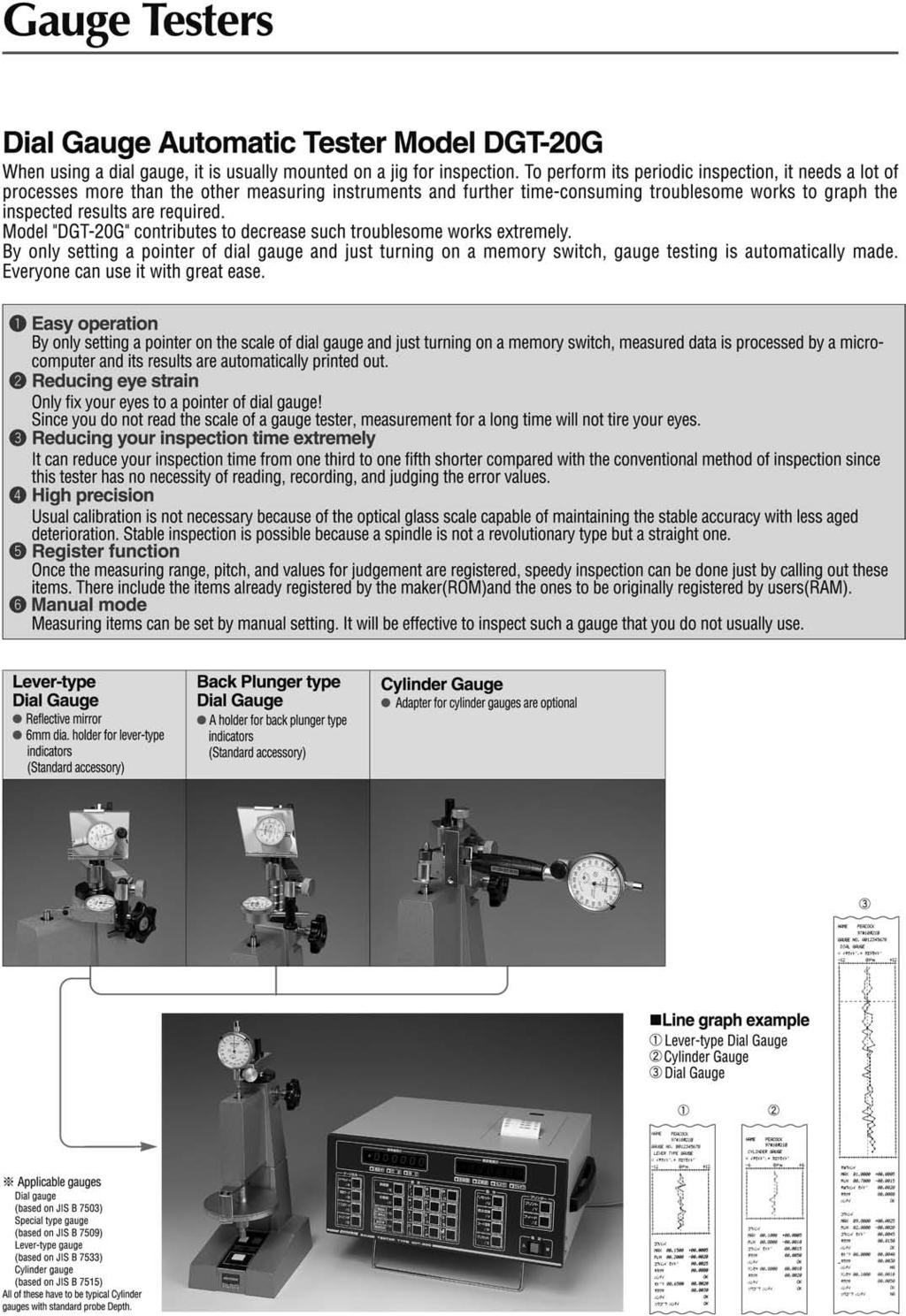
46 Discontinued Discontinued Gauge Testers Gauge Testers


 Cylinder gauges to be possibly inspected All the cylinder gauges of JIS B 71 Standards All the CC and CG models of \"PEACOCK\" 0 Center Adjustable stand A Base 40 Cursor lens")
47 Gauge Tester ( Dial Indicator Testing Equipment ) Gauge Tester ( Cylinder Gauge Testing Equipment ) Dial Gauge Tester NB This is a calibration tester having a high precision micrometer with the minimum scale of 1m. It can be used in order to calibrate dial gauges as well as other displacement gauges. The stancion is vertically adjustable according to the type of gauges and reading is done while looking at the scale plate and the cursor line. Cylinder Gauge Tester CCT- This is a calibration tester used exclusively for cylinder gauges having a high precision micrometer with the minimum scale of 1m. An outer cylinder is held erectly so that deflection may not affect the measurements and a center rod for pressing is provided on the moving bed in order to prevent from errors due to the difference of measuring force. Gauge Tester Gauge Tester Lever-type dial gauge Back plunger type dial gauge Component Names Inspection of dial gauges is also possible. Component Names Gauge fixing screw Gauge supporting frame Center clamp Graduation disk Column Height adjustment stand Magnifying mirror with reference line Micrometer head Base Main pillar (.) Cylinder gauges to be possibly inspected All the cylinder gauges of JIS B 71 Standards All the CC and CG models of "PEACOCK" 0 Center Adjustable stand A Base 40 Cursor lens Graduation board Micrometer Adjustable stand B Stand jam 1 6mm 1mm 1mm 60mm 00mm 0160mm 1600mm 0400mm Micrometer head Graduation Measurement Range Forward Accuracy (µm) Feed per revolution Spindle tip Gauge fixing dimension Micrometer head Graduation Measurement Range Forward Accuracy (µm) Feed per revolution NB 0.001(1m) 0 under 1 0.rev. Carbide chip mm dia. mm dia. CCT under 1 0.rev. Carbide chip Spindle tip
48
49 SECTION 6 Thickness Gauges Dial Thickness Gauges (mm, 0.001mm) Dial Swift Gauge Pearl Scale Snap Caliper Dial Thickness Gauges (Large Type) (mm, 0.0mm) 6 Dial Lens Gauge Dial Sheet Gauges (mm, 0.0mm) Dial Pipe Gauges Dial Thickness Gauge (Roller Type) Dial Upright Gauges Constant Pressure Thickness Gauge


 New H-0.")


 H- Graduation: mm Range: 0~mm Ball")
 H-1A Graduation: mm Range: 0~mm mm flat contact point and anvil (Metal) Bottle Wall")
 G-")
 G- Graduation: mm Range: 0mm G-1A mm flat contact point and anvil (Ceramic)")
 G-4 G-1M Graduation: mm Range: 6mm")

 ±0 ±0 ±0 ±0 ±0 ±0 ± ±0 ±0 ±0")
50 Dial Thickness Gauges 6 mm type New New 6 These thickness gauges are especially handy for measuring thickness of small parts, metal, rubber, vinyl, paper, foil and other sheet material. The objects to be measured is clamped by simple lever operation. The measured values are read directly on the dial gauge. Since the anvil and the contact point are adjusted for parallelism, accurate measured values are obtained. New New H Graduation: mm Range: 0~mm mm flat contact point and anvil (Ceramic) New H-0.4N Graduation: mm Range: 0~mm Measuring force inital pressure 0.4N New H-.4N Graduation: mm Range: 0~mm Measuring force final pressure.4n Dial Thickness Gauges G Graduation: mm Range: 0~mm mm flat contact point and anvil (Ceramic) New G-0.4N Graduation: mm Range: 0~mm Measuring force initial pressure 0.4N New G-.4N Graduation: mm Range: 0~mm Measuring force final pressure.4n The frame on the anvil side is cut, which to be flush contact point, anvil and frame. H-0 Graduation: mm Range: 0~mm 0mm flat contact point and anvil (Metal) H- Graduation: mm Range: 0~mm Ball type contact point and anvil H-0 Graduation: mm Range: 0~mm Bottle Wall Thickness Gauge 0mm flat contact point and anvil (Metal) H-1A Graduation: mm Range: 0~mm mm flat contact point and anvil (Metal) Bottle Wall Thickness Gauge (Roller type anvil) H- Graduation: mm Range: 0~mm Ball type contact point and roller type anvil Dial Thickness Gauge G-0 Graduation: mm Range: 0~mm 0mm flat contact point and anvil (Metal) G- Graduation: mm Range: 0~0mm G-0 mm flat contact point and anvil (Ceramic) Graduation: mm Range: 0~mm 0mm flat contact point and anvil (Metal) G- Graduation: mm Range: 0mm G-1A mm flat contact point and anvil (Ceramic) Anvil side is adjustable More than mm range is comparative measurement. Graduation: mm Range: 0~mm mm flat contact point and anvil (Metal) G-4 G-1M Graduation: mm Range: 6mm Spherical contact point Anvil side is adjustable More than mm range is comparative measurement. Graduation: mm Range: 0~mm 6mm flat contact point and anvil (Ceramic) Graduation Range G G-0.4N G-.4N G-MT G-1A G-1M G- G- G-4 G-0 G-0 H H-0.4N H-.4N H-MT H-1A H- H- H-0 H G-/G-4 : Measuring range of dial gauge is mm. Throat depth Accuracy (µm) ±0 ±0 ±0 ±0 ±0 ±0 ± ±0 ±0 ±0 ±0 ±0 ±0 ±0 ±0 ±0 ±0 ±0 ±0 ±0 Contact Point Dia Parallelism (µm) Metal 6 0Metal 1 0Metal 0 Metal 0Metal 1 0Metal 0 Measuring force less than(n) 1. Initial pressure 0.4N Final pressure.4n Initial pressure 0.4N Final pressure.4n


 Throat depth The dial swift gauge is used for the same purpose as an ordinary micrometer to measure")

 Measuring force less than (N) 1.")

51 Dial Thickness Gauges mm type PAT. No New thinkness gauges with 0.001mm graduations. Newly developed special frame minimizes inspecting errors resulting from thermal changes. Zero reference point will remain accurate even after many hours of use or extreme swings in temperature. Pearl Scale Handy Size: Pearl Scale is compact and light. It is so handy that you can either hang it from your neck or carry it in a pocket. Easy Measurement: You can measure size or thickness of an object you want to measure, just by holding it between a contact point and anvil, and pressing a knob lightly by your finger. A division of scale shows 0.1mm, and you can measure up to 0mm by this gauge. 6 A knob is up when a gauge is released. You only have to press a knob to make a quick measurement. Since the tips of contact point and anvil are narrowed, you can hold even a small object by your fingers for measurement. PS-1 Graduation: 0.1mm Range: 0mm Dial Thickness Gauges Dial Swift Gauge G-6C G-7C Graduation Range 01 0 Dial Swift Gauge G-6C Graduation: 0.001mm Range: 0~1mm mm flat contact point and anvil (Metal) Throat depth The dial swift gauge is used for the same purpose as an ordinary micrometer to measure outside sizes. The spindle is always pulled upward by the force of the spring. The knob at the top of the gauge is pushed down by finger to clamp an object in measurement. It will show its power for measurement of thickness, heights and diameters. 0 0 Accuracy (µm) ± ± Contact Point Dia Parallelism (µm) G-7C Graduation: 0.001mm Range: 0~mm mm flat contact point and anvil (Metal) Measuring force less than (N) Snap Calipers Since the back of gauge is flat, you can measure an object, while laying your gauge on a desk or table. Easy measurement of thickness, outer diameter, inner diameter and depth. Handy size with excellent functions. Minimum reading : 0.1mm. With 0.1mm graduation of a gauge, you can easily read measured values, which makes your work more efficient. To measure thickness and diameter of balls. To measure groove width and inner diameter. Pearl Scale Snap Calipers Graduation Range Throat depth Accuracy (µm) Dia Q-1 Graduation: 0.0mm Range: 0~mm Contact Point Parallelism (µm) Q ±0. EG-1 for measurement of inner diameter and outer diameter. Graduation: 0.1mm Measurement of thickness: 0-0mm Measurement of inner diameter: -mm Measurement of depth: 0-0mm (EG- only) EG- for measurement of inner diameter, outer diameter and depth. To measure depth and step depth. (EG- only.)


 (Roller type) J-A J-B Graduation 0.")


 material or aluminum (AL).")
 K- Graduation: mm Range: 0~0mm mm flat contact point and 0mm anvil (Metal) K-7 (Production on request) Graduation: 0.")
 Custom order available Optional 0,40 and 0mm contact D Dial Sheet Gauges")
52 6 Dial Thickness Gauges (Large type) Dial Sheet Gauges mm and 0.0mm 6 These large thickness gauges having extended throat depth to measure at the center of wide sheets. The sheet gauges can measure wide sheets since the throat depth of this gauges having 00, 00 and 690mm. K-1 Graduation: mm Range: 0~0mm K- Graduation: 0.0mm Range: 0~mm J-A Graduation: mm Range: 0~0mm J-B Graduation: 0.0mm Range: 0~mm mm flat contact point and 0mm anvil (Metal) 0mm flat contact point and anvil (Metal) Dial Thickness Gauge (Large type) (Roller type) J-A J-B Graduation 0.0 The gauge sits by stand mm flat contact point and0mm anvil (Metal) Range 00 0 Throat depth 140 Accuracy (µm) ± ±0 Dial Thickness Gauge Roller type Special gauges for measuring of horizontally sliding a gauge with an object to be in inspected laid since the contact point and anvil are made with the roller. Convenient to continuously measuring thickness of thin objects, paper, rubber and film etc. Contact Point Dia Parallelism (µm) 0 0mm flat contact point and anvil (Metal) Custom order available Optional 0,40 and 0mm contact points and anvils are available. Please specify material for contact point and anvil, either Metal (SK) material or aluminum (AL). Measuring force less than (N).0.0 T (01mm) K- Graduation: mm Range: 0~0mm mm flat contact point and 0mm anvil (Metal) K-7 (Production on request) Graduation: 0.0mm Range: 0~0mm 0mm flat contact point and anvil (Metal) K-4 Graduation: 0.0mm Range: 0~0mm mm flat contact point and anvil (Metal) Custom order available Optional 0,40 and 0mm contact points and anvils are available. Please specify material for contact point and anvil, either Metal (SK) material or aluminum (AL). D Dial Sheet Gauges Graduation Range Throat depth HR-1 Accuracy Roller contact points (µm) OD Width Measuring force less than (N) Parallelism (µm) HR ± 7.0 Graduation K-1 K- 0.0 K- K K K-7 is production on request. Range Throat depth Accuracy (µm) ± ±0 ± ±0 ±0 Contact Point Dia Parallelism (µm) 0 0 Measuring force less than (N)
 Snap type (Spindle is manually pushed down) P-1 Graduation: mm Range: 0~mm P- Graduation: mm Range: 0~1mm P- Graduation: mm Range: 0~1mm We manufacture")
 Please specify the desired Measuring force.")
 Minimum bore D Maximum wall thickness T ±0 ± ±..1 9.0 1 1 Depth L 0 0 Measuring force less than (N) 1.")

 D 6 4 Dial Thickness Gauge (Special Order) The dial lens gauge can measure convex, concave,")

53 6 Dial Pipe Gauges Dial Thickness Gauge (Special Order) 6 Special gauges for measuring wall thickness of pipes. Lever type (example of use) Snap type (Spindle is manually pushed down) P-1 Graduation: mm Range: 0~mm P- Graduation: mm Range: 0~1mm P- Graduation: mm Range: 0~1mm We manufacture with low or high measuring force according to your needs. Maximum Measuring force under.4n (40gf) Minimum Measuring force over 0.4N (40gf) Please specify the desired Measuring force For measuring thickness of hair For measuring thickness of paper world Dial Pipe Gauges Dial Lens Gauge D T P-1 P- P- L Graduation Range Dial Lens Gauge Accuracy Pipe size measurable (µm) Minimum bore D Maximum wall thickness T ±0 ± ± Depth L 0 0 Measuring force less than (N) For different applications, the shape of the contact point and anvil can be special ordered. Dial face with personal logo Special order dial faces Both Contact Point and Anvil needle type D Examples of modification for contact point and anvil Both Contact Point and Anvil ball type.4 Both Contact Point and Anvil are 0mm diameter flat type (also available in and 0mm) D 6 4 Dial Thickness Gauge (Special Order) The dial lens gauge can measure convex, concave, convexo-concave and any other lenses in the same gauge by replacing the two contact points and the anvil. Applied examples concave convex a steel ball b convexo-concave b Please specify D Both Contact Point and Anvil are horizontal blade type Both Contact Point and Anvil are vertical blade type Please specify D Needle type Contact Point and Flat type Anvil. Ball type Contact Point and Flat type Anvil. c c c Replaceable Flat contact point (Standard accessory) Graduation Range Accuracy (µm) Throat depth GL Graduation: mm Range: mm maximum lens diameter measurable maximum lens thickness measurable Measuring force less than (N) GL ± Anvil side is adjustable D Please specify D and thickness. D Please specify D and thickness. D D = mm diameter (also available in0, and 0mm).4 D D = mm diameter (also available in0, and 0mm)

 are available to meet your measurement. 6 Compact Handy type FFG series (PAT.No.0747) Dial Upright Gauges R1-A Graduation: 0.")
 Vulcanized rubber / Thermoplastic")
 Adhesive interlined cloth (common weave / common knit / non-woven) Stockinet (common knit) Unwoven / interlined cloth Adhesive interlined cloth (non-woven) ZI709 ZI70 K67 K67 K6 K60A K60A")
 Gauge installed Range Graduation F-RE 0.")
 1. 1.4.0 Measuring depth Effective measuring range 0 Total height 191 190 FFG-1 FFG- FFG-4 FFG- FFG-6 FFG-7 FFG- FFG-9 FFG-11 FFG-1 Graduation 0.")
54 Dial Upright Gauges 6 R series Best suited for measuring precision parts and testing materials like rubber, leather, fabric and plastic etc. Rubber, leather, urethane and film can be easily measured by this system. The table of R1 series are adjustable up and down by the nut installed side way. The dial gauge is affixed to the body. Constant Pressure Thickness Gauges (Special Order) Constant Pressure Thickness Gauges can be made to comply with JIS by attaching exact weights that create the specific pressures needed to measure different materials. Three types (FFG. FFA. FFD series) are available to meet your measurement. 6 Compact Handy type FFG series (PAT.No.0747) Dial Upright Gauges R1-A Graduation: 0.001mm Range: mm Effective measuring range: mm R1-C Graduation: mm Range: 0mm Effective measuring range: 0mm Measuring material JIS No. Applied Shrink package film Polyethylene package film Ethylene film Polyvinyl chloride film Leather Vulcanized rubber / Thermoplastic rubber (Hardness IRHD less) Vulcanized rubber / Thermoplastic rubber (Hardness IRHD less) Vulcanized rubber / Thermoplastic rubber (Hardness IRHD more) Vulcanized rubber / Thermoplastic rubber (Hardness IRHD more) Urethane form Common fabric (basic / fuzzy material) Adhesive interlined cloth (common weave / common knit / non-woven) Stockinet (common knit) Unwoven / interlined cloth Adhesive interlined cloth (non-woven) ZI709 ZI70 K67 K67 K6 K60A K60A K60A K60A K640 L96 L6 L1 L L6 FFG-1 FFG-1 FFG-1 FFG- FFG-4 FFG- FFG-6 FFG-7 FFG- FFG-9 FFG-11 FFG-11 FFG-11 FFG-1 FFG-1 Constant Pressure Thickness Gauges (Special Order) R1-A R1-B R1-C Dial Indicator (standard attachments) Gauge installed Range Graduation F-RE F-RE 07F-PL 0 Indication error (µm) ±7 ±1 ± R1-B Graduation: mm Range: mm Effective measuring range: mm Table diameter Contact point dia. Measuring force less than (N) Measuring depth Effective measuring range 0 Total height FFG-1 FFG- FFG-4 FFG- FFG-6 FFG-7 FFG- FFG-9 FFG-11 FFG-1 Graduation Range 7 Indication error (µmm) ± ± ± ± ± ± ± ± ± ± Throat depth Contact Point dia (ømm) (19.6mm ) (0.4mm ) (19.6mm ) (0.4mm ).7 (cm ). (cm ) 16 (cm ) Anvil dia (ømm) Measuring force N(gf) 1.±0.1 (1±1) less than 0. (less than 0) less than 0. (less than 0) 0.±0.04 (0±4) 0.1±0.1 (1±) 0.44±0.1 (44±) 1.1±0.6 (11±6) less than 0.7 (less than 7) less than 0. (less than ) less than 0.4 (less than 40) Parallelism (µm)
 ± ± ±0 ±0 ±0 ±0 ±0 ±0 ±0 ±0 ±0 ±0 ±0 Measuring material JIS No.")
 Vulcanized rubber / Thermoplastic rubber (Hardness IRHD more) Vulcanized rubber / Thermoplastic rubber (Hardness IRHD more) Urethane form")
 Tensile properties of plastics ZI709 ZI70 K67 K67 K60 K60 K6 K60A K60A K60A K60A K640 L96 L6 L96 L1 L L6 K711 FFA-1 FFA-1 FFA-1 FFA- FFA- FFA- FFA-4 FFA- FFA-6")
 Anvil dia (ømm) 40 40 0 0 0 0 0 0 0 0 0 0 0 Spindle lifting Lever Release Lever Release Release Release Release Lever Release Lever Release Release Lever Stand type R1 type R1 type SIS-6C")
 0.44±0.1 (44±) 1.1±0.6 (11±6) less than 0.7 (less than 7) less than.4 (less than 40) less than 0. (less than ) less than 0.4 (less than 40) less than 1.")
55 6 Constant Pressure Thickness Gauges (Order) 6 Stand type FFA series Digital type FFD series (with data output) Constant Pressure Thickness Gauges (Special Order) FFA-1 FFA- FFA- FFA-4 FFA- FFA-6 FFA-7 FFA- FFA-9 FFA- FFA-11 FFA-1 FFA-1 FFA-7 Graduation Range 7 Indication error (µm) ± ± ±0 ±0 ±0 ±0 ±0 ±0 ±0 ±0 ±0 ±0 ±0 Measuring material JIS No. Applied Shrink package film Polyethylene package film Ethylene film Polyvinyl chloride film Leather Artificial leather Sheet rubber Vulcanized rubber / Thermoplastic rubber (Hardness IRHD less) Vulcanized rubber / Thermoplastic rubber (Hardness IRHD less) Vulcanized rubber / Thermoplastic rubber (Hardness IRHD more) Vulcanized rubber / Thermoplastic rubber (Hardness IRHD more) Urethane form Common fabric (basic / fuzzy material) Adhesive interlined cloth (common weave / common knit / non-woven) Common fabric (basic / fuzzy material) Stockinet (common knit) Unwoven / interlined cloth Adhesive interlined cloth (non-woven) Tensile properties of plastics ZI709 ZI70 K67 K67 K60 K60 K6 K60A K60A K60A K60A K640 L96 L6 L96 L1 L L6 K711 FFA-1 FFA-1 FFA-1 FFA- FFA- FFA- FFA-4 FFA- FFA-6 FFA-7 FFA- FFA-9 FFA- FFA- FFA-11 FFA-11 FFA-1 FFA-1 FFA-1 Throat depth Contact Point dia (ømm) (19.6mm ) (0.4mm ) (19.6mm ) (0.4mm ).7 (cm ) 11. (1cm ). (cm ) 16 (cm ) (7.cm ) Anvil dia (ømm) Spindle lifting Lever Release Lever Release Release Release Release Lever Release Lever Release Release Lever Stand type R1 type R1 type SIS-6C special SIS-6C SIS-6C SIS-6C SIS-6C SIS-6C SIS-6C SIS-6C SIS-6C SIS-6C SIS-6C Measuring force Parallelism N(gf) (µm) 1.±0.1 (1±1) less than 0. (less than 0).9±0.1 (9±) less than 0. (less than 0) 0.±0.04 (0±4) 0.1±0.1 (1±) 0.44±0.1 (44±) 1.1±0.6 (11±6) less than 0.7 (less than 7) less than.4 (less than 40) less than 0. (less than ) less than 0.4 (less than 40) less than 1.7 (less than 17) FFD-1 FFD- FFD- FFD-4 FFD-6 FFD-7 FFD- FFD- FFD-1 Range FFD-1 Indication error (µm) ±4 ±4 ±0 ±0 ±0 ±0 ±0 ±0 ±0 Graduation Measuring material JIS No. Applied Shrink package film Polyethylene package film Ethylene film Polyvinyl chloride film Leather Artificial leather Sheet rubber Vulcanized rubber / Thermoplastic rubber (Hardness IRHD less) Vulcanized rubber / Thermoplastic rubber (Hardness IRHD more) Vulcanized rubber / Thermoplastic rubber Common fabric (basic / fuzzy material) Adhesive interlined cloth (common weave / common knit / non-woven) Tensile properties of plastics ZI709 ZI70 K67 K67 K60 K60 K6 K60A K60A K60A L96 L6 K711 FFD-1 FFD-1 FFD-1 FFD- FFD- FFD- FFD-4 FFD-6 FFD-7 FFD- FFD- FFD- FFD-1 Display digit 4digit Power supply AC Adapter 0V to 40V Data output RS-C Throat depth Contact Point dia (ømm) (0.4mm ) (19.6mm ) (0.4mm ) 11. (1cm ) (7.mm ) Anvil dia (ømm) Measuring force N(gf) 1.±0.1 (1±1) less than 0. (less than 0).9±0.1 (9±) less than 0. (less than 0) 0.1±0.1 (1±) 0.44±0.1 (44±) 1.1±0.6 (11±6) less than.4 (less than 40) less than 1.7 (less than 17) Parallelism (µm) Constant Pressure Thickness Gauges (Special Order)


 6.")

56 6 Special Order Available FFG Series FFA Series FFD Series Handy type Stand type Digital type Please specify what you want to measure as following: 1. Material of measurement work-piece:. JIS Standard No. or its equivalent standard:. Resolution: mm, 0.001mm 4. Measuring force:. Diameter of Contact Point (ex., mm) 6. Type of Constant Pressure Thickness Gauge Please check FFG FFA FFD Handy type Stand type Digital type 7. Other requirement:
57 SECTION 7 Dial Caliper Gauges LA Series -Outside- LB Series -Inside- 7


58 Dial Calipers 7 LA series (Outside measuring of ODs and thicknesses) 7 The dial caliper gauge show its great power in measurement of inside and outside sizes, wall thickness, groove width and hole diameters and any other shapes and sections that is not apparently accessible. Applied Example -- outside -- adjustment LA-1 Graduation: 0.1mm Range: 0~0mm Throat depth: 10mm LA- Graduation: 0.1mm Range: 0~0mm Throat depth: 40mm LA-7 Graduation: mm Range: 0~60mm Throat depth: mm Adjustable frame The LA-7 can measure an absolute value in a measuring range of mm It allows measurement of comparative values in more than mm movement Dial Calipers LA- Graduation: 0.1mm Range: 0~0mm Throat depth: 400mm LA-9 Graduation: 0.1mm Range: 0~0mm Throat depth: 0mm LA- Graduation: mm Range: 0~0mm Throat depth: 0mm The tip of the bottom frame mm Flat Rocking Contact Point. Note: Throat Depth is changed by Measuring Range. Contact us more detailed information. Ex. LA-1 Dial Calipers Range Throat Depth LA-4 Graduation: 0.0mm Range: 0~0mm Throat depth: 90mm LA-6 Graduation: mm Range: 0~mm Throat depth: 60mm LA- Graduation: 0.0mm Range: 0~0mm Throat depth: mm LA- Graduation: 0.1mm Range: 0~0mm Throat depth: 10mm LA-1 LA- LA- LA-4 LA- LA-S LA-6 LA-7 LA- LA-9 LA- Graduation Range Indication error ±0. ±0. ±0. ±0.1 ±0.1 ±0.1 ±0.0 ±0.0 ±0. ±0. ±0.0 Throat depth ~ 0mm 0~ 60mm 0~ 0mm 0~0mm 0~10mm mm 1mm mm 91mm 6mm Dimensions see page 0 H1 H H H


59 7 Dial Calipers 7 LA-11 Graduation: Range: Throat depth: 0.1mm 0~0mm 1mm LA-1 Graduation: 0.1mm Range: 0~10mm Throat depth: mm see page 1 LA- Graduation: Range: Throat depth: 0.1mm 0~0mm 00mm LA-1 Graduation: Range: Throat depth: mm 0~0mm 1mm LA-14 Graduation: mm Range: 0~mm Throat depth: 70mm LA-14 is for comparative measurement. LA-0 Graduation: Range: Throat depth: 0.1mm 0~0mm 1mm Example Dial Calipers Name of parts LA-1 Graduation: Range: Throat depth: 0.1mm 0~0mm 0mm LA- Graduation: Range: Throat depth: 0.1mm 0~0mm 0mm LA-4 Graduation: 0.1mm Range: 0~0mm Throat depth: 600mm Max. opening frame 00mm Note: Throat Depth is changed by Measuring Range. Contact us more detailed information. Ex. LA-1 Range 0~ 0mm 0~ 60mm 0~ 0mm 0~0mm 0~10mm Throat Depth mm 1mm mm 91mm 6mm Dial Calipers H1 H Thickness H4 H 0 L A 1 0 LA-11 LA-1 LA-14 LA-0 LA-1 LA- LA- LA-4 LA-1 Graduation Range Indication error ±0. ±0. ±0.0 ±0. ±0. ±0. ±0. ±0.4 ±0.0 Throat depth Dimensions see page 0 H1 H H H


, 4,, 6, 7,, 9, mm")


60 7 LB series (Inside measuring of ID and groove widths) Adjustable type 7 LB-1 Graduation: 0.1mm Range: ~90mm Throat depth: 1mm LB- Graduation: 0.1mm Range: ~90mm Throat depth: 10mm See page LB-7 Graduation: mm Range: ~70mm Throat depth: mm Adjustable frame LB-7S Graduation: mm Range: 1~mm Throat depth: 0mm Adjustable frame LB- Graduation: mm Range: ~0mm Throat depth: 0mm LB-4 Graduation: mm Range: ~0mm Throat depth: 0mm LB-7V Graduation: mm Range: ~mm Throat depth: 0mm Adjustable frame LB-14 Graduation: mm Range: 0~mm Throat depth: 70mm Adjustable frame Applied Example -- inside -- movement Dial Calipers LB- Graduation: mm Range: 0~40mm Throat depth: mm LB-6 Graduation: mm Range: 0~0mm Throat depth: 0mm Handy type adjustment Note: Throat Depth is changed by Measuring Range. Contact us more detailed information. Ex. LB- Dial Calipers LB- Graduation: mm Range: 0~10mm Throat depth: 90mm LB-9 Graduation: mm Range: 0~40mm Throat depth: 10mm Graduation LH- Graduation: mm Range: ~10mm Throat depth: 0mm Range Indication error Range mm 1mm 0mm 0mm 90mm Throat depth Throat Depth up to 0mm up to 4mm up to 70mm up to 4mm up to 10mm Height of contact point Dimensions for contact point LB-1467LH- LB-7V LB-7S LA-14LB-14. SR SR0. S1. M0.4 length.6 M0.4 length.6 H H material SK hardened Hmm (height of contact point), 4,, 6, 7,, 9, mm type are available as options. Order pair as 1 set (pcs). 1. carbide M0.4 material : SK hardened LB-1 LB- LB- LB-4 LB- LB-6 LB-7 LB-7S LB-7V LB- LB-9 LB-14 LH ±0. ±0. ±0.0 ±0.0 ±0.0 ±0.0 ±0.0 ±0.0 ±0.0 ±0.0 ±0.0 ±0.0 ±0.0 For LH-, the range of accuracy is to 0mm. In case of 0mm or more, check the tolerance with Master Gauge (SK hardened,one unit with frame) (SK hardened,one unit with frame) 7
 type Inside measuring (LB) type Measuring thickness at the back end of a projecting workpiece LA-14 LA-1 LA-0 Measuring thickness at the back end of a projecting")
61 7 PEACOCK Caliper Gauges are quite useful for such measurements of O.D. or I.D. thickness and diameter which appear so difficult to measure. Examples Outside measuring (LA) type Inside measuring (LB) type Measuring thickness at the back end of a projecting workpiece LA-14 LA-1 LA-0 Measuring thickness at the back end of a projecting workpiece Dial upward type LA- LA-S Measuring thickness of a cup, hat or helmet LA type Measuring thickness or OD in a narrow, confined place LA type Measuring center OD of a boss LA-11 Floating type: lower contact point has a flat mm diameter LA- Dial Calipers Measuring thickness by hurdling a projecting area LA type Measuring thickness by hurdling a projecting area LA- Measuring thickness of a large workpiece or part. A: workpiece sizes up to 00mm are accessible (LA-4). Measuring thickness or OD in a narrow, confined place LA-9 LA-11 Measuring ID or groove width LB-16 Measuring ID of a very shallow hole A : approximately mm lip is sufficient (LB-7V) Measuring ID or an O-ring groove LB-16 Measuring ID by straddling the center boss LB-7 LB-14
62 SECTION Applied Dial Gauges Dial Depth Gauges Digital Depth Gauges Dial Inside Gauges Dial Hole Gauge Digital Hole Gauge Applied Contact Points Bench Center


 Length Width 7F-T 1.4 7F-T 1.")

 16. M.0.4 T- 4 (1 0') 0.")
 Range Accuracy (µm) Dial Gauge Base Gauge")

63 Dial Depth Gauges It measure a depth from top bottom of bottomed holes, a depth of narrow grooves, a value of step height of stepped surfaces and a depth of types engraved in matrices. The dial gauge furnished offers a correct measured value since it can measure an object under measurement with a given measuring force. Dial Depth Gauge Round Base type New New 01600mm intervals M T-1 Graduation: mm Range: 0~160mm contact points are included 0~160mm. Replace the contact point in accordance with the measuring range. 1. M.0.4. steel T-1W Graduation: mm Range: 0~0mm 4 extension rods are included 0, 40, 60 and 0mm. Recombine the extension rods, in accordance with the measuring range. Two center-pointer type. 16 M.0.4 T- 1 Graduation: mm Range: 0~mm 1. M.0.4. steel T-W Graduation: mm Range: 0~0mm T-6A Base Outer dia..0 Needle Contact Point dia..0 Graduation: mm Range: 0~mm T-6B Base Outer dia..0 Needle Contact Point dia. 1.0 Graduation: mm Range: 0~mm Base 14 Range Accuracy (µm) T-6A T-6B Dial Gauge Base Gauge installed Graduation Range Measuring force less than (N) Length Width 7F-T 1.4 7F-T M Dimensions ( ( ) are T-6B ) Custom order available Dial Depth Gauges 1.. steel T-B Graduation: mm Range: 0~mm The dial face is at a right angle with the contact point, which facilitate easy reading from the upside. M T-C 4. 0' Graduation: mm Range: 0~mm Needle Contact Point (XT-C) 16. M.0.4 T- 4 (1 0') 0.1 Graduation: mm Range: 0~mm Needle Contact Point (XT-) 7.1 M.0.4 T Graduation: 0.001mm Range: 0~1mm Needle Contact Point (XT-4) Range Accuracy (µm) Dial Gauge Base Gauge installed Graduation Range Measuring force less than (N) Length Width T F-T T-1W WF-T T F-T T-W WF-T T-B B-T T-C 0 1 7F-T T F-T T-4 01 F F with Reversed Inner Dial Base is hardened and polished S H O CK mm JEWELED P R O F O ( 1) M Base is hardened and polished. Dial Depth Gauge


 Graduation Accuracy (excluding")


64 Digital Depth Gauges Dimensions for Digital Depth Gauges T1-07 T T1-0 MODE ON/OFF SET T-17 MODE ON/OFF SET T1-0 Graduation: 0.001mm Range: 0mm T-17 Graduation: mm Range: mm T-0W Graduation: 0.001mm Range: 0mm hardened and ground 1 Hv hardened and ground Hv over 60 T1-7 Graduation: mm Range: 0mm T-7W Graduation: mm Range: 0mm T-0W7W T-17 Contact Point (XS-1).4 T MODE ON/OFF SET Digital Depth Gauges T-17 Graduation: mm Range: mm Contact Point (XT-) Graduation Accuracy (excluding quantized error) T-17 Graduation: mm Range: mm Contact Point (XT-4) Gauge installed Range Base flatness T6-17 Graduation: mm Range: mm Option T MODE T-17 ON/OFF SET T XT- 60 T6-17 MODE ON/OFF SET Dimensions for Digital Depth Gauges T1-0 T1-7 T1-17 T-0W T-7W T-17 T-17 T DG-0 DG-7 DG-17 DG-0 DG-7 DG-17 DG-17 DG contact points mm (0mm intervals) XT
 Replace the extension rods according to a measuring range.")


 Graduation Range GH-1 Graduation: mm Range: mm Dial")
 UHA")
")
 Indication")
65 Dial Inside Gauge Dial Hole Gauge Extension rods 6pcs. (,, 0, 40, 0, 140mm) Replace the extension rods according to a measuring range. The Dial Hole Gauge is used for measurement of a bore diameter or groove width. Adjustable upper frame may be changed as desired, thus securing a wide measuring range. The contact point has an outer dia of mm and a height of mm. (R 1mm ball, M1.7 x 0.mm.) Capable of continuously measuring comparatively large bores or inside wall surface with a given measuring force using flexibility of the dial gauge. Outer dimension U-1 With Magnetic Base The gauge proper can be secured to the measuring position by the magnet base. Graduation: mm Range: 0~0mm (Measuring range of dial gauge: mm) Graduation Range GH-1 Graduation: mm Range: mm Dial Gauge Accuracy(µm) Reading Measuring force less than (N) Measurable bore ID Measurable depth less than GH Digital Hole Gauge Dial Inside Gauge UHA Graduation: mm Range: 66~0mm (Measuring range of dial gauge: 4mm) UHA Graduation: mm Range: 66~0mm (Measuring range of dial gauge: 4mm) with shorter pointer New New U-1 UHA UHB UFA UFB UHA UHB New Graduation Range UHB Graduation: mm Range: 0~9mm (Measuring range of dial gauge: 4mm) UHB Graduation: mm Range: 0~9mm (Measuring range of dial gauge: 4mm) with shorter pointer Reading New UFA Graduation: mm Range: 9~1mm (Measuring range of dial gauge: mm) Indication error 1 revolution 1 revolution (Adjacent error) 1 revolution revolutions UFB Graduation: mm Range: 1~10mm (Measuring range of dial gauge: mm) Dimensions ( ( ) are UFAUFB ) 1 () 6 (46.) Size with no pressure on spindle Measurement range Whole measuring range Magnetic Power (kg) (unit: µm) Measuring force less than (N) Graduation Accuracy (excluding quantized error) Gauge installed GH-17 Graduation: mm Range: ~mm Range Dimensions Measurable bore ID Measuring force Measurable depth less than GH DG-17 Less than 0.9N SR MODE GH-17 ON/OFF SET Dial Hole Gauge Digital Hole Gauge
 This instrument have a 0mm length of lever and used to measure depth of holes. The flat contact point (XS-) is installed to the dial gauge to hold the back when used.")
 XY-1 Lever angle is fixed XY- Lever angle is adjustable Dimensions -SR1. 0 0 11 4 7 0 0 -SR.7 OA Max.")
 The contact point is tilted in its moving direction by the cam, and it includes two types; tilted to 4and 60.")


 1.4 1.4 Center distance OA 00 Max. work capacity dia.")
66 Applied Contact Points Bench Center Lever type Contact Points Dial Gauges supplied on request (Recommend a Dial Gauge with Lug Back and install it to a Magnet Stand.) This instrument have a 0mm length of lever and used to measure depth of holes. The flat contact point (XS-) is installed to the dial gauge to hold the back when used. High-accuracy eccentricity tester used to measure eccentricity of articles over a wide range of rotary cutting tools, arbors, crankshafts, gears, piston heads or grinding stones and to check circles for roundness. (dial gauges are not furnished) XY-1 Lever angle is fixed XY- Lever angle is adjustable Dimensions -SR SR.7 OA Max. Center distance: 00mm Applied Contact Points Angle Contact Points Dial Gauges supplied on request (Recommend a Dial Gauge with Flat Back due to light weight.) The contact point is tilted in its moving direction by the cam, and it includes two types; tilted to 4and 60. The contact point is convenient for measurement on locations where it is impossible to straightforwardly install the dial gauge and to use it for a jig. Hold the stem when used. Exterior dimensions XZ-1 XZ- Dial Gauge mount Dial Gauge mount Dimensions (OA ) OA Left tail stock Clamp lever for left tail stock Cross slide Center Marked line Dial gauge A Scale (00mm) Center 4-9 Right tail stock Set ever for center Fine adjustable screw for center Clamp lever for right tail stock Handle for traverse feed Bed Adjustable screw for marked line Travel lever for center Handle for ongitudinal feed Arm Strut Adjustable screw for arm B Clamp screw C Longi udinal feed stand Bench Centers XZ-1 Range: 1.mm Angle: 4 XZ- Range: 1.mm Angle: 60 Angle Range XZ-1 XZ Angle 90is available on request. Moving distance Measuring force less than (N) Center distance OA 00 Max. work capacity dia. 0 Use center Overall dimensions Approx. weight Feed gear (A) mm (B) mm (C) mm (kg) Right and left Back and forth MT No. Approx. 7 Approx Screw feed Screw feed
 0-00TON with Dust Proof Rubber (Spec.")
67 L 0 00 OVER LOAD GAUGE for TIRE CURING MACHINE For passenger vehicle tires and those for truck and bus tires (Made to order) We, "PEACOCK" make OVER LOAD GAUGES for TIRE CURING MACHINES that applied our Dial Gauge. Example pictures of Over Load Gauge for TIRE CURING MACHINE 0-00TON with Back Plate & Dust Proof Rubber (Spec. Pointer 1 rotation: 0.mm) 0-00TON with Dust Proof Rubber (Spec. Pointer 1 rotation: 0.mm) 1. For making the Dial Plate, please let us know the angle for range of graduation to meet with the Tightening force (TON). *see diagram as under. Example Spec. Pointer 1 rotation: 1mm 1 Dial Plate a Angle divide equally b Angle divide not equally Dead Zone Dead Zone Angle ex)1. Dial Numeral ex) Kg D A O O V E R Unit Unit *Please let us know pointer 1 rotation 0.mm or 1mm.. We provide the Over Load Gauge with Back Plate to meet with your Tire Curing Machine. Dust Proof Rubber can be installed to the Spindle of Over Load Gauge. Backs a Flat Back b with Back Plate Ø ±0.0 ± Back Plate ± ± Note. 4-M are set screws for Back Plate to Body. (6 points hole finished on Back Plate.) Please contact your local "PEACOCK" distributor for your further inquiry or write to us at: peacock-tokyo@peacockozaki.jp
68 SECTION 9 Stands Dial Gauge Stands Magnetic Stands Magnetic Holder 9

 SIS-6C SIS-7 Table surface Table size Effective moving range Allowable measuring depth Stem installed SIS-6C SIS-7 Quench-hardened and polished Ground cast iron surface 0mm diameter")
 Dial Gauge Stands Mounting example for Dial Gauge (mm Stem) Base Dimensions Main column Support column Height Length Width Diameter Length")

69 9 Dial Gauge Stands Renewed Stand designed for precision measurement of standard dial gauges, lever dial gauges and lever electric micrometers, rigid in construction and easy in fine adjustment of gauge indication by the original fine adjusting device. Economy-wise popular stand 9 Split Collar Split Collar SIS-4F With fine adjustment (Dial Gauge and Pic Test Indicator are not furnished.) SIS-6C SIS-7 Table surface Table size Effective moving range Allowable measuring depth Stem installed SIS-6C SIS-7 Quench-hardened and polished Ground cast iron surface 0mm diameter 7474mm 0 to about 0 mm 0 to about 0 mm Approximately 6.mm mm Approximately mm mm can be installed when split collar is removed. Mounting example for Pic Test Indicator (6mm Stem) Dial Gauge Stands Mounting example for Dial Gauge (mm Stem) Base Dimensions Main column Support column Height Length Width Diameter Length Diameter Length SIS-4F Attachment (For Mounting a Dial Gauge) Weight (kg) Included attachments 1. for Dial Gauges. for Lever type Dial Indicators The stand is designed for standard dial gauges and digital linear gauges and is rigid and easy to work. Table surface Table size PDS- PDS-F Ceramic with grooves Ceramic without grooves Split Collar 00mm 00mm PDS- Effective moving range 0 to about 0 mm 0 to about 0 mm Split Collar Allowable measuring depth Approximately 60mm Approximately 60mm PDS-F Stem installed mm (0mm) Dial Gauge Stands Horizontal Stands 0mm can be installed when split collar is removed.
 or standard dial gauge (held by back lug) is attachable to all types of these magnetic stands. The dial gauges are not furnished.")

 Magnetic Stands Measurement surface in parallel direction Width High surface in parallel direction Base Length Low surface in parallel direction Height")
70 9 Magnetic Stands The stand using a powerful magnet features simple and stable holding at any place, easy handling, compactness and reasonable price. Either lever dial gauge (held by 6 mm stem) or standard dial gauge (held by back lug) is attachable to all types of these magnetic stands. The dial gauges are not furnished. Magnetic Holder The magnetic holder holds a dial gauge using the attractive forced of the magnet fit in the base. It has features of being compact, simple to handle and stable in holding. The YMH-1 is for general dial gauges. 9 YMH-1 (Dial Gauge is not furnished) Magnetic Power kgs Dimensions YM-1 YM- YM- Magnetic Power 0kgs Magnetic Power 40kgs with fine adjustment Magnetic Power 4kgs Examples (YMH-1) high angel (unit : mm) Magnetic Stands Measurement surface in parallel direction Width High surface in parallel direction Base Length Low surface in parallel direction Height Measurement at various angles in parallel directions Magnetic power (kgs) Suitable indicators YMH For general dial gauges 7 Measurement surface in vertical direction Magnetic Holders YM-1 YM- YM-
71
72 SECTION Signal Indicators Signal Gauges Signal Checker Signal Box Signal Gauge Set-Up Signal Gauge Connections Diaglam


73 Signal Gauges/Signal Checker 0.001mm, mm and 0.0mm Type S- With its high resolution of 0.001mm scale, it is most suitable for judgement of the values measured on finished parts with high accuracy. S-7 With its resolution of mm scale, it is generally used. Its pointer is in an anti-shock structure so as to give stable discriminating signals. S-9 With its most gross scale of 0.0mm, it is applicable to select grossly worked parts and as cast parts at the low-est costs. SC-A Once its tolerance is set, a dial gauge is dismounted before using it so that its endurance is really improved. With its large tolerance setting range of mm, it is most suitable for judgement of the measured values in a wide tolerance range. Outer Dimension S-, S-7 & S-9 Outer Dimension SC-A S- Graduation: 0.001mm Measurement range: 0.1(0.0)mm S-7 Graduation: mm Measurement range: 1.0(0.)mm S-9 Graduation: 0.0mm Measurement range:.0(1.)mm SC-A Measurement range: mm GB-1A Example of mounted back cover with lug (option) Signal Gauges Signal Checker Spindle Movable Range Graduation Tolerance Setting Range Accuracy Measuring Force Contact capacity Number of judgement Stages Cord length Contact point Stem diameter Operating temperature range Options Dial indicator for setting Weight Cable signal table Caution S- mm 0.001mm 0.1 (0.0) mm 0.00mm S-7 mm mm 1.0 (0.) mm.0 (1.) mm 0.00mm 0.0mm Less than 1.N (10gf) MAX DC4V 0mA Three stages of NG, OK and NG m X-A 060 C Code Length m m Back cover with Lug (GB-1A) 10g S-, S-7, S-9 COM (blue) black NG with and at ON NG (red) NG with and at ON NG (white) OK with,,and at OFF Code Length m m 7F, F g SC-A COM (blue) black NG with,,and at OFF OK (red) OK with and at ON NG (white) NG with,,and at ON When the current of to 0 ma is used to drive a photocoupler,etc.,the contact may be worn a little earlier. In SC-A type, the COM terminal is body-grounded (If leak current is found in other devices, put a gauge into floating status before mounting it). In SC-A type, a spindle can be set in a range from its free status to mm. Although it may be movable in excess of this limit, you cannot set it in such an excessive level in order to protect the spindle. In SC-A type, when a dial gauge is dismounted after setting the tolerance, never forget to mount a dust protective cap. S-9 4mm 0.0mm SC-A mm In SC-A type, the minimum readable value depends on a dial gauge to be attached. mm 0.00mm Example of supported stem Split collar (WB-1) Signal Gauges Signal Checker
, OK (green), NG (yellow) AC00V (VA)")
74 Signal Box Long life LED makes a replacement of lamp unnecessary. It is equipped with judgement output by relay contact. SB- Display Colors Relay contact capacity Outer Dimensions Cord length Power supply Usable Gauges Relay contact output Weight Output of Relay Contacts SB- NG (red), OK (green), NG (yellow) AC00V (VA) MAX (resistance load) (L)mm(H)6mm(D)160mm m (with plug) AC0V, AC00V 0 60Hz S-, S-7, S-9, SC-A Three stages of NG, OK, and NG NG COM OK NG 100g Discontinued Dimensions Signal Box Signal Controller
 and hold a signal gauge on a stand, etc. b.")


75 Signal Gauge Set-Up Signal Gauge Connections Diagram How to Use Signal Gauge (S-, S-7, S-9) Name of Parts Main body Pointer Lower limit setting knob Upper limit setting knob Dial face Dial face bezel knob Instructions a. Prepare a judgement master (standard sample) and hold a signal gauge on a stand, etc. b. Adjust and fix the position of judgement master so that a gauge pointer indicates zero, and move the contact point up and down several times so as to confirm the pointer's stable position. c. When setting a lower limit of tolerance value, remove the master and turn the lower limit setting knob so as to adjust a pointer at a certain graduation. d. When setting an upper limit of tolerance value, turn the upper limit setting knob so as to adjust a pointer at a certain graduation while fully pushing up the contact point. e. After setting the upper and lower limit, move the spindle up and down serveral times to confirm that a pointer's indication is within the tolerance value. Stem or back cover with lug is used to support the gauge. S- S-7 S-9 SC-A Stem Spindle Contact point (X-A) Signal Checker (SC-A) Instructions Signal Gauge Set-Up Name of Parts Lower limit setting knob Stem Spindle Contact Point (X-A) Dust protective cap Upper limit setting knob Lift knob a. Prepare a judgement master (standard sample) and hold a signal gauge on a stand, etc. b. Prepara a dial gauge for setting tolerance value No.7 (mm to mm) and remove the dust protective cap by a hexagon wrench attached to the gauge. c. Turning the lift knob allows the spindle to move up and down. The pointer of dial gauge moves according to its movement. d. Connect this checker with a signal box or a controller. e. Prepare a judgement master (standard sample),on which push this checker to the position where the lower limit of tolerance value can be set, and fix it by a supporting device. f. Set the indicator of dial gauge at zero of a dial and turn the lower limit setting knob fully in the clockwise direction. g. Set the upper limit of tolerance value at a certain position while turning the lift knob in the clockwise direction. h. Turn the upper limit setting knob in order to adjust the indications (signals) of signal box or controller to the switching position of OK and NG at the upper limit of tolerance value. i. Remove the master and turn the lift knob in the counter clockwise direction to set the lower limit of tolerance value. j. Turn the lower limit setting knob to adjust the indications (signals) of signal box or controller to the switching position of OK and NG at the lower limit of tolerance value. k. Move the spindle up and down several times by the lift knob to check the right adjustment. l. After your setting, turn the lift knob in the counter clockwise direction until the spindle is fully pushed down. m. When you use this checker without dial gauge, never forget to mount the dust protective cap on it. Stem is used to support this checker. Connector Positive contact output SB- Solderless Terminal Gauges can be connected to a signal box by attached connectors. When connecting with a signal controller or a sequencer, remove the connectors and use solderless terminals. Sequencer Signal Gauge Connections Diagram
76 Example of Use Measurements of Length and Outer Diameter (glass bottles, etc.) OK Length NG Other Dimeter NG After measuring by two signal gauges and two signal boxes,selection (OK, NG) is automatically controlled. Measurement of Deviation (Wheels, etc.) Selection (OK, NG) is performed while turning an object and measuring its deviation. Example of Use Measurement of Thickness (paper rolls, etc.) Multiple points are measured using a lot of signal gauges and selection (OK, NG) is performed by a signal box, or controller.
77 11 SECTION Digital Indicators Digital Dial Gauge Linear Gauge Digital Counter Application Series Deep Hole Bore Gauge Technical Glossary 11


 DL- (Lever Type) D- D-")
 C-00")
 0.")

78 11 Overview of Digital Gauges & Display Combinations Display and Supporting Units 11 Measuring range Resolution mm mm mm 1.mm 0mm 0mm 0mm DG-17 DG-7 Counter DG-0 PDN mm PDN mm 0.001mm C-00 (Simple function) DL- (Lever Type) D- D- New DN- D-0 New DN-0 D-0 D-0 C-700 (Malti-function) mm D-UZ RS-C CM-B (Counter with Comparator) C-00 (Simple function) DL-S (Lever Type) D-S D-S New DN-S D-0S New DN-0S D-0S D-0S C-700 (Malti-function) mm CM-B (Counter with Comparator) Overview of Digital Gauges & Display Combinations mm 0. µm mm 0.1 µm D-SS D-HS C-7HS (0.1µm Resolution) Display and Supporting Units
 to easily legible positions. Very compact, and long mm stroke.")
 1 1. 9. GB-10 Option Example of Connection DG-0 DG-7 64 6. 1..1 A B 60.")
:inch/mm(convertible) (B):ON/OFF KB-0C DG-17 Resolution: Range: mm 0~1.mm DG-7 Resolution: Range: mm 0~mm DG-0 Resolution: 0.")
 Display (LCD display) Measuring force (when correctly positioned) Operating temperature Battery Data")
 symbol 6 digit 999.999 with ( ) symbol Less than 0.9N Less than 1.")
 M. x 0.")

 Display")
79 11 Digital Indicators Cordless Type 11 The batteries in these digital indicators have a service life of approximately 000 hours under normal use. Digital display can be rotated (approx. 70 ) to easily legible positions. Very compact, and long mm stroke. (DG-7, DG-0) RS-C data output capability. No warm-up required. Switch on, and it's immediately ready to use. Clear LCD display. Dimensions (DG-0DG-7DG-17) GB-10 Option Example of Connection DG-0 DG A B 60. DG-17 Digital Indicator Applied Series (A):inch/mm(convertible) (B):ON/OFF KB-0C DG-17 Resolution: Range: mm 0~1.mm DG-7 Resolution: Range: mm 0~mm DG-0 Resolution: 0.001mm Range: 0~mm Optional accessories Lug Back GB-10 Opto-cable KB-0C Opto-cable KB-0USB Digital Indicators Range Resolution Accuracy (excluding quantized error) Display (LCD display) Measuring force (when correctly positioned) Operating temperature Battery Data output Mounting method Contact point Weight Functions DG-17 DG-7 DG-0 1.mm mm mm 0.001mm mm 0.00mm digit with ( ) symbol 6 digit with ( ) symbol Less than 0.9N Less than 1.1N +~40 C One CR0 type lithium battery (included) RS-C port (opto-cable sold separately) Supported by mm stem, (Lug back, GB-10 is optional) M. x 0.4 Thread with carbide ball (XB-1) 0g ZERO RESET Resetting to zero at any desired position PRESET Preset at a desired value DATA HOLD Data can be held for direct data output to outside computer MMINCH Easily switch between metric and inch systems Low battery warning display "b" signifies low battery (Battery dies within ~ hours after "B" is first displayed) Display rotation Display can be rotated up to 70for easy reading Counting direction conversion Plus and minus directions, for spindle movement, can be selected. Lifting Lever LL-0 Lifting range (0mm) Release RE-0 For direct RS-C connection to your PC. Lifting range (01mm) Connecting cable for PC (USB type) Digital Indicators
 Range: 0~0mm Examples (PDN-CC) Examples (PDN-PP) PDN-1 Resolution: 0.001mm (convertible to mm) Range: 0~0mm PDN-1 Resolution: 0.")
 RS-C Output DCV Input 1 14 The measurement data is transmitted automatically when measurement stops.")
80 Digital Gauges 11 Integrated Display Type 11 PDN-CC (for Cylinder Gauge) Resolution: 0.001mm (convertible to mm) Range: 0~0mm PDN-PP (for Measuring Height of Milling Blade) Resolution: 0.001mm (convertible to mm) Range: 0~0mm Examples (PDN-CC) Examples (PDN-PP) PDN-1 Resolution: 0.001mm (convertible to mm) Range: 0~0mm PDN-1 Resolution: 0.001mm (convertible to mm) Range: 0~0mm Options (for PDN-1) Flat Back No. GB-D0Finger Lever No. LL-D0 Release No. RE-4 Lifting Lever No. LL-PD Dimensions (PDN-1 PDN-CC PDN-PP) RS-C Output DCV Input 1 14 The measurement data is transmitted automatically when measurement stops. The Gauge sets the top of the first tooth as the standard value (0), then each tooth from the second is compared the first tooth one after another. Digital Gauges Options (for PDN-1 and PDN-1) Input Adapter No. IF-1 IF-1 can input a measuring data directly to a cell of the spreadsheet such as EXCEL by converting the keyboard signal. The driver is unnecessary as USB terminal connection. Gauge Stand No. SIS-6C Digital Display can be rotated approx. 0 Micro-USB Connector Mode Switch Reset Switch Power ON/OFF Switch MODEL PDN-1 S.4Steel Ball (X-) MADE IN JAPAN MODE RESETPOWER PDN-1 PDN-1 Range 0mm 0mm Resolution Convertible mm and 0.001mm (Set 0.001mm at the time of shipment) Accuracy (excluding quantized error) 0.001mm Display: 0.00mm mm Display: mm 0.001mm Display: 0.004mm mm Display: mm Measuring force Less than 1.N (Without Spring: less than 0.1N) Less than.0n (Without Spring: less than 1.0N) Response speed 00mm / sec. Contact Point X- (M. x 0.4) X-9 (M. x 0.4) Display rotation 0 Power Supply AC0-40 V% 0/60Hz (AC Adapter) Operating temperature 040(no condensation) Accessories AC Adapter AC Adapter Finger Lever No. LL-D0 Functions PDN-1 and PDN-1 Convertible mm and 0.001mm Judgement: Three Stage of -NG, OK and +NG (OK : Green, +NG : Red, -NG : Red) Counting Direction Conversion Data Output RS-C Options for PDN-1 Flat Back No. GB-D0 Release No. RE-4 Finger Lever No. LL-D0 Lifting Lever No. LL-PD for PDN-1 and PDN-1 Input Adapter No. IF Cylinder Gauge CC-series CC-0 CC-01 CC-1 CC- CC- CC-C CC-4 CC- CC-6 Cylinder Gauge is not furnished and supplied only on request. 6mm 1mm 1mm 60mm 00mm 0mm 0160mm 1600mm 0400mm CG-series CG-01 CG-1 CG- CG- CG-C CG-4 CG- CG-6 1mm 1mm 60mm 00mm 0mm 0160mm 1600mm 0400mm Dimensions (PDN-1) Micro-USB Connector DCVInput Digital Display can be rotated approx. 0 PDN-CC PDN-PP Range 0mm 0mm Resolution Convertible mm and 0.001mm (Set 0.001mm at the time of shipment) Accuracy (excluding quantized error) 0.001mm Display: 0.00mm mm Display: mm Measuring force Less than 1.N Response speed 00mm / sec. Display rotation 0 Power Supply AC0-0 V% 0/60Hz (AC Adapter) Operating temperature 040(no condensation) Data Output RS-C Back Flat back No. GB-D0 Functions for PDN-CC for PDN-CC and PDN-PP Minimum Value Display Convertible mm and 0.001mm Minimum Display with Statistical Operation. Judgement : Three stage of -NG, OK and +NG Auto Start : Automatically start to measure. (OK : Green, +NG : Red, -NG : Red) Auto Stop: Automatically stop to measure. Counting direction Conversion Error Detect: Prevent the error measurement by Error Detect Options Same as PDN MODEL PDN-1 9 RS-COutput 1 6. RESET POWER MODE Power ON/OFF Switch Reset Switch Mode Switch Stem 0mm Stem mm S.4Steel Ball (X-9) Digital Dial Gauge with Stand

 D- Resolution: Range: D-S mm 0~mm Resolution: 0.")
81 Linear Gauges 11 Measurement range(0~mm) 11 Lever Type Best suited for deviation measurement. Pencil Type Best suited for confined conditions. Small Type Best suited for work in confined space measurement. Dimensions DL-DL-S 1... Slide metal ± Dovetail D-D-S D- 1 Carbide DL- Resolution: Range: DL-S mm 0~mm Resolution: 0.001mm Range: 0~mm DL-S Lever slides vertically, straight up and down, as shown, ( to eliminate error caused by arc operation.) D- Resolution: Range: D-S mm 0~mm Resolution: 0.001mm Range: 0~mm D-UZ Resolution: mm Range: 0~mm D-UZ Examples Linear Gauges Range Resolution Accuracy (excluding quantized error) Measuring force Mounting method Contact point Weight Cable length Operating temperature Output signal Featuares DL- mm mm Less than 0.6N DL-S 0.001mm 0.00mm 6.mm hole on lug or dovetail at bottom mm carbide 10g m (Standard) D- D-S mm 0.00mm mm Less than 0.N mm stem.4mm steel (X-) 0.001mm 0.00mm 160g 00g Option available 0~40 C 90 phase difference, 0µm pitch (R0-PBM Tajimi connector) Lever type probe is best recommended for measuring TIR or narrow space. Contact point easy adjustable to any desired position. Pencil type is especially made for setting up in extremely confined conditions. Dust proof rubber attached. Gauge suitable for use in dusty and moist environment. Compatible standard counters C-00 C-700 CM-B Options Customer must specify if application is up-side-down. The measuring force Lever moves linearly, unlike the arc movement in a lever type dial indicator. D-UZ mm mm mm Less than 1.0N 6.mm hole on lug back.4mm steel (X-7) Testing TIR (Total Indicator Run-out) of a cylinder Measuring Angles Gauges are set at position X and Y and the difference between them is converted into angle for judgement. (In this example, the loft angle of a golf club is measured and printed out) Multi-point testing of a thick board A B Multi-Point Measuring Mount the same number of linear gauges to measure the numbers of points where measurement is needed. Measured data is processed by a multicounter with CPU and printed out on a printer. Internal surface measurement of a cylinder Measuring Glass Tubes Outer diameter, thickness, and thickness variation of glass tubes such as fluorescent tubes are measured and displayed. Built-in printer prints out the measured data. Linear Gauges


 7 4 6. 1. 19. standard type comes with lug on back covergb-idx for flat back cover,please specify GB-DX R 0 0.1 0 countersunk hole depth 1mm 1 6 90. 9.7 1 DIGITAL GAUGE MODEL D-0 OZAKI MFG CO,LTD 0 0.")

82 11 Measurement range (0~mm, 0~0mm ) 11 mm and 0mm measurement ranges are the easiest to use. Used in conjunction with digital counters, these gauges can be set up in places where dial gauges are now being used. Set the gauge by either stem or lug back. For lifting spindle, both lever and release types are available. D- Resolution: mm Range: 0~mm DN- Resolution: Range: Rectangular wave output type DN-DN-SDN-0DN-0S For use in electrically noisy environments. For applications requiring extra long cables.( to 0 meters are available) New mm 0~mm DN-0 Resolution: Range: New mm 0~0mm 9 Dimensions (D-D-SD-SSD-0D-0SDN-DN-SDN-0DN-0S) DIG TAL GAUGE MODEL D-S OZAKI MFG CO,LTD stem. (4.) standard type comes with lug on back covergb-idx for flat back cover,please specify GB-DX R countersunk hole depth 1mm DIGITAL GAUGE MODEL D-0 OZAKI MFG CO,LTD D-S Resolution: 0.001mm Range: 0~mm DN-S New Resolution: 0.001mm Range: 0~mm Output wave-formdn-dn-0 DN-0S New Resolution: 0.001mm Range: 0~0mm Output wave-formdn-sdn-0s M v v A A 0 v øb v v øb 0v Linear Gauges D- D-S DN- DN-S D-0 D-0S DN-0 DN-0S Range Resolution Accuracy (excluding quantized error) Measuring force Cable length Mounting method Contact point Operating temperature Weight Output Signal Compatible standard counters Options 0~40 C µ except DN-S, Release (RE-4) Lifting lever (LL-1) Dust proof rubber (BG-) Flat back (GB-D), screws (S-1) Customer must specify if application is up-side-down. Release (RE-4) Flat back (GB-D0) Customer must specify if application is up-side-down. The measuring force changes when the gauge is inverted. The measuring force changes when the gauge is inverted. New New New New Options Split collar (WB-1) 1 Split collar above is used on the mm stem during mounting to prevent malfunction due over tightening. Securing by means of screw directly in stem may result in malfunction. Dust proof rubber (BG-) Release (RE-4) Lifting lever (LL-1) Compressible dust proof rubber fits all D-, D-S, D-S, D-SS, DN-, DN-S gauges. (Stroke under mm) Total length 0mm Linear Gauges
 D-0 Resolution: mm Range: 0~0mm Special Gauges For High Temperature Applications D-0HT (mm Resolition) For Dusty Applications D-0WA")
 Resolution (D-0S is not suited for high temperature) Dust-proof rubber protects spindle. Equivalent to IP-4.")
 (In order to fasten at this position, M4L =4mm screw or equivalent is used) Movable range about 0mm Wrench fixing place for contact point exchange (Attached wrench should be used) 40 D-0")
 Linear Gauges Range Resolution Accuracy (excluding quantized error) Measuring force Cable length")

83 11 Measurement Range (00mm, 00mm) 11 With very sturdy 0mm stem. Ultra-high precision achievable with exclusive gauge stand (PDS-) D-0 Resolution: mm Range: 0~0mm Special Gauges For High Temperature Applications D-0HT (mm Resolition) For Dusty Applications D-0WA D-0SWA For Dusty Applications D-0WA D-0SWA D-0S Resolution: 0.001mm Range: 0~0mm This special gauge can be used up to 6 C temperature. mm (0.00mm) Resolution (D-0S is not suited for high temperature) Dust-proof rubber protects spindle. Equivalent to IP-4. (Protection against oil & water is not available) Dimensions (D-0D-0SD-0HT) Option Level mounting clamp (GB-0) ø 4. countersunk hole 7. (depth mm) (In order to fasten at this position, M4L =4mm screw or equivalent is used) Movable range about 0mm Wrench fixing place for contact point exchange (Attached wrench should be used) 40 D-0 Resolution: mm Range: 0~0mm D-0S Resolution: 0.001mm Range: 0~0mm 6 Attached finger level is fixed here to pull up the spindle Dimensions (D-0D-0S) Linear Gauges Range Resolution Accuracy (excluding quantized error) Measuring force Cable length Mounting method Contact point Operating temperature Weight Output signal Compatible standard counters Accessories Features Option D-0 D-0S D-0 D-0S 0mm 0mm mm 0.001mm mm 0.001mm mm 0.004mm mm 0.00mm Less than.0n Less than.n m 0mm stem or fastening by M4 screws at two positions 0~40 C 40g 0g 90 phase difference, 0µm pitch (R0-PBM Tajimi connector) C-00 C-700 CM-B If Spindle inner spring is removed, measuring force will be that of spindle itself (only when in upright position) D-0, D-0S 1.0N (0gf) D-0, D-0S 1.1N (1gf) Recommended Gauge stand is PDS- Level mounting clamp (GB-0) see page 141 Customer must specify if application is up-side-down. The measuring force changes when the gauge is inverted. Option Level mounting clamp (GB-0) Fasten with M6 screws 4. countersunk hole 7. (depth mm)(in order to fasten at this position, M4L=4mm screw or equivalent is used) Movable range about 0mm Attached finger lever is fixed here to pull-up spindle Supporting example with 0mm stem (By mounting it below, adjustment of position becomes smooth) Wrench fixing point for change of contact point (Attached wrench should be used) Use M or M6 screw Linear Gauges


 Range: 0~mm D - SS mm 0.000mm 0.001mm M. 0.4 S.4mm steel (X-) mm stem or back cover with lug(6.")
84 11 High Resolution Type 0.1µm and 0.µm 11 Use of linear scale improves accuracy and reduces error due temperature influences. Dimensions (D-HS) Extension cables for Linear Gauges Extension Cable Extension cable with metal sheathing 1 1 DIGITAL LINEAR GAUGE MODEL D-HS MADE IN JAPAN OZAKI MFG.CO.,LTD. 16 spindle pull-up back lever ,, and meters are standard length. and meters are standard length. 9 Common of Linear Gauges Linear Gauges Range Resolution Accuracy (excluding quantized error) Measuring force Cable length Operating temperature Contact point Mounting method Weight Output signal Compatible standard counters Accessories Options D-SS Resolution: 0.000mm(0.µm) Range: 0~mm D - SS mm 0.000mm 0.001mm M. 0.4 S.4mm steel (X-) mm stem or back cover with lug(6.mm hole) Release (RE-4) Back cover with lug (GB-1DX) Accuracy list 0g 90 phase difference, µm pitch (R0-PBM Tajimi connector) Parallel adjustment Contact point (X-) Gauge stand (PDS-) D-HS Resolution: mm(0.1µm) Range: 0~mm With spindle pull-up back lever D - HS mm mm 0.000mm Less than 1.0N m 0~40 C M. 0.4 S.4mm steel (X-) mm (no provision for back cover with lug mounting) 00g 90 phase difference, µm pitch (appoximate Sinusoidal wave) (R0-PBM Tajimi connector) C-7HS (exclusively for D-HS) X- When using 'Flat' contact point, choose contact point which has parallel adjustment in relation to anvil surfaces as shown in picture. Items Type of Output signal (A) gauges Output signal (B) Displacement transducer type Power supply Signal cable length Output connector, Receiver connector Output signal (A) 1µm resolution Output signal (B) µmµm resolution Output signal (C) µmµm resolution Output signal (D) 0.µm0.1µm resolution Operating temperature Output Frequency Contact point Output signal (A) wave-form (1µm resolution) A B V 0m 0 m m 1m 0m After multiplying 1µm pulse by where 1µm = 1 generated pulse. Common specifications DL-S, D-S, D-S, D-0S, D-0S, D-0S DL-, D-, D-, D-0, D-0, D-0, D-UZ Glass linear scale (scale pitch 0µm) (D-SSD-HS: pitch µm) 1DCV % (consumed current 40mA) m (,, and m extension cables are available) 4 core shied cable & oil proof type Gauge side (R0-PBM) Counter side (R0-RF) Tajimi connectors phase signal with 90 phase difference, 0µm pitch, sinusoidal wave-form phase signal with 90 phase difference, 0µm pitch, approximate sinusoidal wave-form phase signal with 90 phase difference, 0µm pitch, square wave-form (gauges: DN-, DN-0) phase signal with 90 phase difference, µm pitch, sinusoidal wave-form (gauges: D-SS, D-HS) 0~40 C (except for high temperature type) 0~0KHz M. x 0.4 (contact points for dial gauge can be used) PP=1.V Signal Connector R0-PBM (manufactured by Tajimi) Pin arrangement F E G H D A C Pin No. A B C D E F G H Signal GND A 1V B NC NC NC Wire Color black blue red white unused shielded wire (FG) unused unused Linear Gauges
85 11 Digital Counters New Type of Digital Counters No. C-00 No. C Equipped with large display functions and various measurement functions,our Digital Counters can be installed in a Control Panel or placed on a desk due to their compact designs. Displayed digits Selection of m Selection of 1m Display Power supply voltage & power consumption Operating temperature Compatible Linear Gauges Selection of m display Selection of 1m display High-luminance LED display with 7segments (red) AC0VAC40V9VA or lower 0+40 DL-D-D-D-0D-0D-0D-0 DN- DN-0 D-UZ DL-SD-SD-SD-0SD-0SD-0SD-0SDN-SDN-0S Accessories AC power cord (m): One cord Metal fittings for panel installation: Two units (to be used for installation in panel and securing stand fittings) Stand fittings: One unit (to be used when counter is used as desktop device) Terminal block: Screwless terminal block Usable electric cables: AWG- 1/ Display (C-00/C-700) Simple type Priority on user friendliness. C-00 Display (C-00/C-700) Multi-type User friendliness combined with multi-functionality. C-700 Inch Display (C-00/C-700) Terminal block functions (Rear panel) Length of peeled wire of cables: 9mm Pin alignment 1St/Sp React Latch 4Reset Alarm 6NG 7OK NG 9GND Contorls "START" and "STOP" of MAX, MIN. P-P measurement mode. Controls "SUSPEND" and "START" of P-P measurement mode. Controls "LATCH" and "CANCEL" of measured value. External "RESET" "PRESET" (Function available only in No. C-700) Error signal output Outputs -NG based on OKNG judgment (red LED). Outputs OK based on OKNG judgment (green LED). Outputs +NG based on OKNG judgment (orange LED). GND marked numbers indicate functions available only in No.C-700 Max Display Min Display P-P Display NG () OK NG (1) OK NG () OK NG (1) NG () NG (1) 1NG output in first stage NG output in second stage Dip (1) Dip () Dip sw setting functions (Printed circuit board) SW 1 SW SW SW 4 Select 1m or m Select direction of counting. Select activation or non activation of error output. Select activation or non activation of overflow. SW 1 SW SW SW 4 Settings by Manufacturer Select whether or not to include default values for OK NG judgment. Select either "orthogonal" or "sine" for input waveform. Select either 400msec or 0msec for RESET time. Displays the displacement after halving it. Data Output (C-00/C-700) (Standard function of RS-C, optional function of BCD) RSC RSC RSC Displays the displacement after doubling it. Presetting (C-700) Displays the displacement in terms of inches. OKNG Judgment (C-700) Data output D-Sub9P plug INCH screw Options BCD output board Display functions Pin Alignment NC Rxd Txd NC SG NC RTS CTS NC in out out in CB-BCD Can not be used in combination with RS-C output. Communication mode: Half-duplex asynchronous communication Communication speed: 9600bps Format: 7Bit ASCII Parity: even number Stop bit: 1Bit RTS/CTS: Returned when not in use. Reception command: Transmission request ASCII [T] [t] : Reset ASCII [R] [r] Connection cables: Cross cables (not included) 1/1 display: Displays the measured value as is. 1/ display: Displays the measured value after halving it. display: Displays the measured value after doubling it. INCH display: Displays the value after converting it into inches. Note: With 1m display and display, the lowest digit will be displayed as an even number. Digital Counters Outputs data Maximum Value Display (C-700) Holds the maximum positive value and makes OKNG judgment Displays preset values. Minimum Value Display (C-700) Holds the minimum negative and makes OKNG judgment Outputs OKNG judgment. Deflection Measurement Display (C-700) Holds the difference between the maximum and minimum values (deflection) and makes OKNG judgment Presetting display function Measurement mode function MAXMINPP OKNG judgment function (Refer to terminal output circuit) Dimensions & weight Start/stop measurement.st/sp Suspend/start measurement.react DATA ZERO RESET Measuring Suspending DATA HOLD Zero setting only 144(W)7(H)160(D)mm ZERO RESET Measuring Suspending DATA HOLD Can display preset values Current value dispiay Maximum value(max) RESET action is taken by ST of the Minimum value(min) ST/SP control terminal. V Deflection(P-P) 1k Inside counter Current value mode NGOK NG Maximum value mode OKNG1NG GND Minimum Photo coupler: V(Max ma) value mode Response OKNG1NG time: Approx. 0msec Deflection mode OKNG1NG Time Chart [ No.C-700] Control Terminal Input Circuit Terminal Output Circuit V 1k Inside counter GND Photo coupler: V(Max ma) Response time: Approx. 0msec 90 Pin No.1 ST/SP Pin No. REACT Pin No. LATCH Pin No.4 RESET OUT GND GND Open collector output Voltage: Max DC0V Current: MAX 0mA Inside counter Pin No. ALARM Pin No.6 -NG Pin No.7 OK Pin No. +NG of Digital Counters
 / 0.000mm (0.µm) CM-B Resolution: 0.00mm0.")
 0.000mm (0.µm) 6 digits display with sign 99.9999.6kg AC0VAC40V900V 060Hz 00W0D60Hmm 0 to 40 C storage, at to 0 C 0.0001mm : D-HS 0.")
86 11 with High Resolution with Judgement Function 11 Resolution capability of 0.1µm / 0.µm. Recommended for very high precision measurement. Equipped with Judgement function OK, NG (No Go). Either µm or 1µm resolution setting can be selected. X or 1/ X Display magnification. C-7HS Resolution: mm (0.1µm) / 0.000mm (0.µm) CM-B Resolution: 0.00mm0.001mm convertible C-7HS CM-B Resolution Display Response speed Weight Display Power supply Dimensions Operating temperature Compatible linear gauges Accessories Functions Data output (RS-CBCD OUT) Options mm (0.1µm) 0.000mm (0.µm) 6 digits display with sign kg AC0VAC40V900V 060Hz 00W0D60Hmm 0 to 40 C storage, at to 0 C mm : D-HS 0.000mm : D-SS Built-in tilt stand (tilts the front of the counter up at slight angle for easier reading) RESET For zero reset at any desired position DIRECTION Numerical direction can be changed by DIRECTION switch located on back panel CLOCK OUT Outputs BCD's signal simultaneously (1µsec) ALARM OUT Output abnormal value when response speed is exceeded LATCH IN Holds the display value and external output data RESET IN For zero reset from external unit via its RESET input Output by positive logic, parallel digits and open collector Connector DDK equivalent connector (amphenol type) should be used. It is not attached on the cable side. (7-060 equivalent connector is recommended) Printer (PDP-1N) Statistic operation External RESETLATCH function: C-7HS-RL. Resolution Display capacity Judgement setting display Response speed Quantizing error Judgement Output Judgement Display Operating temperature Power supply WeightDimensions Functions Data output (RS-CBCD OUT) Compatible linear gauges 0.00mm or 0.001mm select by conversion switch For 0.00mm, mm For 0.001mm, mm Lower and Upper limit setting via digital switch of 6 digits each 00mm sec at 0.00mm setting 600mm sec at 0.001mm setting 1 count NG (Yellow), OK(Green) & NG(Red) 0 to 40 Cfor storage, at to 0 C AC0VAC40V(90V 1V) 060Hz.kg 00W0D70Hmm User selectable resolution (0.001mm at time of shipment). Equipped with failure alarms (When counting error or gauge fails, display blinks) Judgement output is constantly on (control output is possible with an additional optional connector) Setting values for judgement is included in NG at shipment (Changeable) BCD output can be connected to, for example, a sequencer by using open collector. Output by positive logic, parallel digits and open collector Connector DDK equivalent connector should be used. It is not attached on the cable side. At 0.00mm setting At 0.001mm setting DL-, D-, D-, D-0, DL-S, D-S, D-S, D-0S Digital Counters Accessories Options Mounting Precaution D-0, D-0, D-0S, D-0S D-UZ, DN-, DN-0 Judgement output connector... 1 pc. (PRC0-1A-4F. Tajimi brand) Additional passfail detection control connector (attachable to the back panel). Includes CM-B-CONT. External RESET LATCH connector is added (on back panel). CM-B-RL. Tilt stand is added (for tilting display for easy viewing). CM-B-ST. When mounting into rack requires the removal of bottom rubber support, screws must be applied at regular intervals. (Avoid screws penetration into body as damage to printed circuit board is high) Digital Counters

(0mm) G-0AG-7AG-17A Resolution and Range (0.0010mm)(0mm) G-0G-7G-17 G-0MG-7MG-17M G-0AG-7AG-17A G-0A.")
 0.00 0.")

87 MODE ON/OFF SET 11 Applied Digital Indicators Digital Thickness Gauges (mm, 0.001mm) The thickness of small parts etc. can be quickly measured by lever operation. Contact Point and Anvil can be modified made to order. 11 Discontinued G-0G-7G-17 Resolution and Range (0.0010mm)(0mm) Dimensions G-0MG-7MG-17M Resolution and Range (0.0010mm)(0mm) G-0AG-7AG-17A Resolution and Range (0.0010mm)(0mm) G-0G-7G-17 G-0MG-7MG-17M G-0AG-7AG-17A G-0A ceramic ceramic hardened and ground HV60 Printer G-0 G-7 G-17 G-0M G-7M G-17M G-0A G-7A G-17A Resolution Accuracy (excluding quantized error) Gauge type DG-0 DG-7 DG-17 DG-0 DG-7 DG-17 DG-0 DG-7 DG-17 Measuring range Measuring depth Measuring force (N) Less than 1.1 Less than 1.1 Less than 0.9 Less than 1.1 Less than 1.1 Less than 0.9 Less than 1.1 Less than 1.1 Less than 0.9 Contact point diameter ø ø ø ø6 ø6 ø6 ø ø ø Contact point parallelism Less than 0.00 Less than Less than Less than 0.00 Less than Less than Less than 0.00 Less than Less than Anvil diameter ø ø ø ø6 ø6 ø6 ø ø ø Applied Digital Indicators
 11 Due to having throat depth mm or 00mm can measure a thickness at the center of wide sheets such as paper, urethane, vinyl, rubber and foil etc.")

 7 0 71 1 7 1 JA-0 JA-7 K1-7 Resolution 0.")

88 7 MODE K1-7 ON/OFF SET 9 MODE ON/OFF SET 11 Applied Digital Gauges Digital Thickness Gauges (Large Type), Digital Sheet Gauge Applied Digital Gauges Digital Upright Gauges (0.001mm, mm) 11 Due to having throat depth mm or 00mm can measure a thickness at the center of wide sheets such as paper, urethane, vinyl, rubber and foil etc. Contact Point and Anvil can be modified made to order. K1-7 Resolution: mm Range: 0mm Best suited to inspect sizes precision parts or to measure thickness of laboratory specimens. JA-0 Dimensions JA-0JA-7 Resolution: 0.001mm Range: 0mm JA-7 Resolution: mm Range: 0mm Dimensions K1-7 R1-0 Resolution: 0.001mm Range: 0mm R1-7 Resolution: mm Range: 0mm Dimensions R SK4 hardened and ground HV over SK4 hardened and ground HV over Resolution: mm Range: 1mm 1 1 Ceramic Table SUS40J lap after heat treatment HV (1) JA-0 JA-7 K1-7 Resolution Accuracy (excluding quantized error) Gauge type DG-0 DG-7 DG-7 Digital Pipe Gauge Measuring range Measuring depth 00 Measuring force (N) Less than 1.1 Less than 1.1 Less than.0 Dimensions Contact point diameter ø ø ø Contact point parallelism Less than 0.00 Less than Less than Anvil diameter ø0 ø0 ø0 R1-0 R1-7 R1-17 Resolution Accuracy (excluding quantized error) Gauge type DG-0 DG-7 DG-17 Measuring range Measuring force (N) Less than 1.1 Less than 1.1 Less than 0.9 Measuring depth Contact point ø ø ø Table diameter ø40 ø40 ø40 Modification for contact point (Special order) P-17 Flat type Replaceable Contact Point Needle type P-7 Resolution: mm Range: 1mm Applied Digital Gauges P-17 Resolution: mm Range: mm P-7 P-17 Resolution Accuracy (excluding quantized error) Gauge type DG-7 DG-17 Measuring range Measuring depth 0 0 S hardened and ground HV over 60 XJ SK4 ground after hardened HV over 60 Measuring force (N) Less than 1.1 Less than 0.9 Measuring hole diameter ø.1 ø.1 Please specify "ød" Accessories for Dial Gauges Replaceable contact points can be installed. Please specify dimension of "H" and "ød" Applied Digital Gauges

 EMCC- EMCC-4 0 160mm 10mm M Intervals mm7 1.4mm less than.")

89 11 Deep Hole Bore Gauge-EMCC Series 11 The EMCC Series can easily measure the inside diameter of deep bore with high accuracy, which has been precision-machined. The EMCC Series advances a detector having an automatic alignment mechanism in line with the inside diameter. Measurement is possible up to the length of M by using an additional extension rod. Measuring range (ID) Measuring depth Number of feeler Thickness of washers Contact Point Contact point's travel and measuring force Extension rods Compatible linear gauges Compatible counters Operations EMCC- 60mm 70mm M EMCC- 0 0mm 90mm M Intervals mm6 Intervals mm11 1,,mm each Lmm (flat type) EMCC- EMCC mm 10mm M Intervals mm7 1.4mm less than.0n Compatible Counter C-00 EMCC mm 10mm M Intervals mm 1,,,4mm each L44mm (flat type) EMCC-L (1 meter rod rods meters) sold separately When Resolution is µm, use D-B When Resolution is 1µm, use D-SB C-00 Test completes only after receiving reference from a master and inserting the micrometer head through a workpiece. Automatic centering mechanism requires no manual "shaking" to center up the micrometer head. Functions Workpiece has to be horizontally level (No test can be performed with the workpiece perpendicular). Dimensions A B C D E F G MIN MAX To make up a complete working unit, it requires an EMCC (~6), an EMCC-L (extension rod set), a linear gauge and a counter. EMCC mm mm M Intervals mm Features The inside diameter of extremely deep can be measured. (Max. M) The inside diameter of the deep hole that was not able to be measured so far can be easily measured with our development of automatic brought to an center position and added to extension rods to the Linear Gauge.. High performance It is possible to measure with high performance as our Linear gauge is used for the detector. (mm, 0.001mm) Easy operation Due to our development of our automatic brought to an center position, the measurement operation is easier than a general inside diameter measuring instruments as only insert the cylinder detector in the hole of measurement work-piece. Efficient measurement Since the easy operation, it is efficient of the measurement for an inspection of the mass production. Excellent indication stability It is necessary to shakes the general cylinder gauge for reads a minimum measurement. However, our EMCC can get the excellent stability of the indication as only insert the detector to the hole of measurement work-piece. Low measuring force The work-piece is not so damaged as the measuring force of contact point is.0n compared with a general cylinder gauges (.0~6.0N) Data record Digital counter have the RS-C output so that the measuring data can be processed. The main usage Internal diameter measurement of extremely deep hole Hydraulic Cylinder, Air Cylinder, Cylinder of Extruder, High accuracy Pipe, Mold for Pipe etc. Extension Rods (1M x pcs) as Optional To insert or pull-out the detector to the hole of measurement work-piece. Display Counter Data displayed by Digitally Selection of a resolution (mm or 0.001mm) No. Range of Display Resolution Quantized error Data output Power supply Weight C-00 At the mm Selection ~00.00~ At the 0.001mm Selection ~0.000~ mm / mm Selectable 1 count RS-C AC0V~AC40less 9VA 90g *see page 14 for more detailed information Deep Hole Bore Gauge- EMCC Series Dimensions Gauge Sensor Resolution Accuracy Cable length Screw pitch of Contact Point Measuring force Remarks D-B D-SB mm 0.001mm mm 0.00mm meters M..4 Less than 0.N are according to D-S Measurement figure Replaceable Feeler Front Guide EMCC Body Movable Contact Point Digital Linear Gauge DIGITAL LINEAR GAUGE H14 MODEL D- Extension Rod Rear Guide Custom-made Specialize Stands
 at a constant pitch is called a linear scale (scale pitch of 0, 16")
90 11 Combination example Technical Glossary 11 What is a "Linear Scale"? Light emitting element Index Main scale As illustrated on the left, a optical glass with vacuum deposition of chrome metal (opaque) at a constant pitch is called a linear scale (scale pitch of 0, 16 or µm is used) The opposite scale to this linear scale is called an Index scale. This is designed to sense two phases of signal mutually having 90degree phase difference for the purpose of discriminating shift direction of the scale. The light intensity of the light emitter is detected by the photo receptor located directly opposite. When a linear scale moves, the photo receptor will receives variation of light and shade. Linear displacement can be measured by counting these electric signals with a counter. (Counting them by 0µm pitch will give µm display resolution and electrically dividing the wave results in 1µm display resolution) Light receiving element About "Quantizing error" In quantization(displacement under the minimum display digit shall be defined as 0 or 1), the point "0" has a width similar to the other numeric values; including "0" closest to "1" and also "0" closest to"1". Therefore, 1 count error is generated in the minimum display digit. (The value "0" is displayed after setting a linear gauge and then pressing the "Reset" switch.) The counter "C-" resolves the quantizing error in 10mm digit by setting the display value of the minimum digit to µm display. (If you need to resolve the quantizing error in 100mm display type, please use "C- SS" with 0.000mm display.) 's zero reference was taken at the s zero reference was taken at the 's zero closer to 1. 's zero closer to 1 Linear Gauge No. D-0S Digital Counter No. C-700 Gauge Stand No. PDS- Difference between "Measuring Force" and "Measuring Pressure" "Measuring Force" Pressure of a contact point pressing a workpiece is defined as measuring force. Generally, as the spindle back spring is integrated in a gauge, it indicate the state in which the spindle is possibly pressed into a workpiece. (A weighted gauge can get a constant measuring force at any position) UnitN(newton) "Measuring Pressure" It is the value indicating the force of contact point pressing a workpiece in a unit area. (measuring force per unit layer). After specifying the area (diameter) of contact point to be in contact to a workpiece, the measuring force to be pressed in a unit area is defined as measuring force. (When it is necessary to specify measuring pressure, a type with an attached weight is usually used since there is no change in the measuring force, even in the stroke of a spindle.) Unit 1Pa = kgfmm Combination example As for more detailed specifications, refer to page 117, 140 and 14. Expression of accuracy Measuring range Accuracy is the difference between the zero reference point and the greatest deviation across the entire measurement range. Xµm represents the combined error Xµm and error Xµm allowed. Xµm represents an absolute value: if an error of Xµm occurs in, error is not allowed (0µm). Accordingly, if an error of Xµm occurs in, error is not allowed (0µm). Thus, Xµm error allowance is harder to achieve than Xµm error allowance. (In this catalog, we use absolute value, Xµm.) Accuracy of Lever-type Linear Gauges (DL-, DL-S) These DL- and DL-S linear gauges are used in applications very similar to lever-type dial indicators. Their accuracy is represented every 0.mm interval, not over the entire measurement range. 00.mm 0.mm1.0mm 1.01.mm 1..0mm The entire measurement range is divided into 4 sections. The largest deviation among these 4 sections will determine accuracy. Technical Glossary
91 11 Methods of Supporting Stem There are methods for mounting of a linear gauge, namely by 'stem' or "lug". As illustrated on the left, please secure a stem by a split collar or a slot. (If a stem is secured directly by a screw or screws, the spindle may not move smoothly.) Please use split collar WB-1 designed exclusively for mm stem. Using split collar (WB-1) Supported by a slot Not advisable for direct bolt fastening of stem Positioning Lever-type Linear Gauges As illustrated on the left for a lever type linear gauge, the lever moves linearly, different from a lever type dial indicator. Lever type dial indicator can be freely set on a workpiece because of its arc movement. However, lever type linear gauge should be set on a workpiece extensively at right angle. (Since no deviation from arc is generated, the measuring range is set to mm wide.) Accurate measurement cannot be attained. About Polarity Conversion When you need the reversed value to be read, for example, in case of depth measurement, "" count should be set in the direction of pulling up of a spindle. In standard counters, you will find this switch on the back panel. ResetPreset Linear gauges can be reset to zero at any position in the measuring range. Counters with preset function can be set a desired value at a desired position. Since values are displayed based on the preset value as a reference, it is suitable for managing the measured values by their absolute values. Reset Preset Technical Glossary Protection Classifications Example of protection classes based on IEC9(DIN4000)(First=protection classes for solid 0 to 6, Second=protection classes for liquid 0 to ) IP-4 Protection Class IP-66 Protection Class Type Class Type Class Represents human body, protection and protection against foreign objects Represents protection against water : Protection against dust 4: Splash proof type Provides protection against dust. No harmful result caused by water splashed from all directions (water splashproof). Represents human body, protection and protection against foreign object Represents protection against water 6: Anti-dust seal type 6: Full waterproof type Provides complete anti-dust protection against dust invasion. Protection that eliminates any water invasion including direct water jet from all directions (completely waterproof).

92 SECTION 1 Parts Drawings New Pic Test Pic Test Dial Gauge Dial Thickness Gauge Dial Lens Gauge Cylinder Gauge 1
Catalog No. A5105 PRECISION MEASURING INSTRUMENTS. Technology. Customizing. Quality ,000U
 R Catalog No. A PRECISION MEASURING INSTRUMENTS Technology Customizing Quality 011.08. 3,000U President's voice We, Ozaki Mfg. Co., Ltd has established in 1916 and came along with Japanese Automotive industry
Dial Test Indicators SERIES 513
 Dial Test s SERIES 513 Narrow or deep places, which cannot be measured with a normal dial gauge, can be easily and accurately measured. Mitutoyo's proprietary new structure permits smooth pointer operation.
JTC TOOL. 1Dial Gauge
 1ial Gauge ial Indicator is surely utilized at manufacturing sites where dimensional high accuracy is needed to be confirmed. The graduation (1- graduation ) depends on usage and Teclock offers kinds of
Dial Test Indicators Comparison measuring instruments which ensure high quality, high accuracy and reliability.
 Dial Test s Comparison measuring instruments which ensure high quality, high accuracy and reliability. SERIES 513 Lever-Type Dial s eature icons Designed to probe surfaces that cannot be reached with a
Dial Indicators. Description of Icon
 Dial Indicators Description of Icon Icon Description Reverse reading type suitable for depth and step measurement. One revolution type for easy and error-free reading Double scale spacing type, easy-on-the-eyes
Level-Type Dial Indicator
 Level-Type Dial Indicator Feature Swiss style precision gear module design, precision display, aluminum or steel housing, ensuring reliability and durability. Produced and calibrated according to German
DISCONTINUED PRECISION MEASURING FOWLER CALIPERS 1 - VERNIER CALIPERS 4 - ELECTRONIC CALIPERS
 FOWLER CALIPERS 1 - VERNIER CALIPERS 4 - ELECTRONIC CALIPERS 52-058-016 Fine quality vernier calipers are constructed of stainless steel. 52-057-004 offers 3-way measurement to accuracy. 52-058-XXX series
FAST CHECK THICKNESS GAGE
 FAST CHECK THICKNESS GAGE Recommended for quick thickness checks of flat sheet materials and wide variety of small parts. Supplied with hardened steel gaging contacts, lifting levers, and clockwise continuous
Inspection Instrument for Indicators Comparison measuring instruments which ensure high quality, high accuracy and reliability.
 Inspection Instrument for Indicators Comparison measuring instruments which ensure high quality, high accuracy and reliability. i-checker SERIES 170 The i-checker is specially designed to calibrate dial
Automatic Level Maintenance Manual SAL-XX W/ AIR DAMPENED COMPENSATOR
 Automatic Level Maintenance Manual SAL-XX W/ AIR DAMPENED COMPENSATOR CST/Berger 2001 SAL 20/24/28/32 PAGE 1 REV. C 071803 Automatic Level Maintenance Manual User Calibration and Testing... 3 Circular
Inspection Instrument for Dial Indicator Comparison measuring instruments which ensure high quality, high accuracy and reliability.
 Inspection Instrument for Dial Indicator Comparison measuring instruments which ensure high quality, high accuracy and reliability. i-checker SERIES 170 The i-checker is specially designed to calibrate
Wenzhou Tripod Instrument Manufacturing Co., Ltd.
 Wenzhou Tripod Instrument Manufacturing Co., Ltd. Website: http://aliyiqi.en.alibaba.com http://www.wzydyq.com/english/ Phone: 86-577-57572515 57572515 Fax: 86-577-57572516 57572516 E-mail: aliyiqi@gmail.com
SAVE 10% INDICATOR PROMOTION INDICATOR PROMOTION. Dial Test, Dial, Digimatic. Effective July 1, 2016 through August 31, 2016
 SAVE 10% Dial Test, Dial, Digimatic Effective July 1, 2016 through August 31, 2016 Effective July 1, 2016 through August 31, 2016 SAVE 10% Quick-Set Test Indicators The most direct gear train design ever
Dial indicators / Dial test indicators / Center instruments Edge finders / Probes / MF measuring fixture system
 Dial indicators / Dial test indicators / Center instruments Edge finders / Probes / MF measuring fixture system Accuracy of dial indicators according DIN 878 Max. permissible range () errors (µm) 0-0.4
Lever-type Dial Test Indicators
 Lever-type Dial Test Indicators G-1 Lever-type Dial Test Indicators TESA IP65 Electronic Dial Test Indicators Provides the advantages of a mechanical test indicator with a digital reading. Inductive patented
Lever-type Dial Test Indicators
 Lever-type Dial Test Indicators www.tesatechnology.com G-1 Lever-type Dial Test Indicators TESA IP65 Electronic Dial Test Indicators Provides the advantages of a mechanical test indicator with a digital
2 - Machining Fundamentals Measurement. Manufacturing Processes - 2, IE-352 Ahmed M El-Sherbeeny, PhD Spring-2015
 2 - Machining Fundamentals Measurement Manufacturing Processes - 2, IE-352 Ahmed M El-Sherbeeny, PhD Spring-2015 Learning Objectives Measure to 1/64 (.5 mm) with a steel rule Reading an Inch-based Vernier
FA A D
 52 Dial Gauge / Plunger Dial / Dial Indicator mm Quotation Range-mm W C D% 10 5 20 / 25 30 50 100 Least Count 0. 01 0. 01 0. 01 0. 01 0. 01 0. 01 Insize Rs. 12 Y 1430 1782 2724 3719 6942 17860 Code 2301-10
Read the following BEFORE getting started:
 BASIC MEASUREMENTS Read the following BEFORE getting started: Ruler: A ruler, or rule, is an instrument used in geometry, technical drawing and engineering/ building to measure distances and/or to rule
Height Master Page 343. Check Master Page 347. Calibration Tools Page 352
 Calibration Instruments Height Master Page 343 Check Master Page 347 Calibration Tools Page 352 342 Digital Height Master Functions ZERO/ABS DATA/HOLD Auto Power OFF after 20 min. non use Low voltage alarm
JTC TOOL. 6Bore Gauge & Micro Hole Test. Dial Indicator (Option)
") Holder ore Gauge & Micro Hole Test Interchangeable Rod nvil Nut Dial Indicator (Option) Holder Clamp Screw Grip Joint Guide Contact Point This is designed for measuring diameter of small holes exclusively
Holder ore Gauge & Micro Hole Test Interchangeable Rod nvil Nut Dial Indicator (Option) Holder Clamp Screw Grip Joint Guide Contact Point This is designed for measuring diameter of small holes exclusively
Electronic Indicators / Dial Gauges / Dial Test Indicators (Lever-Type)
") Electronic Indicators/Dial Gauges/Dial Test Indicators (Lever-Type) Electronic Indicators / Dial Gauges / Dial Test Indicators (Lever-Type) E-1 DIN 2270 NF E 11-053 TESATAST Dial Test Indicators (Lever-Type)
Electronic Indicators/Dial Gauges/Dial Test Indicators (Lever-Type) Electronic Indicators / Dial Gauges / Dial Test Indicators (Lever-Type) E-1 DIN 2270 NF E 11-053 TESATAST Dial Test Indicators (Lever-Type)
product manual H-3220A Benkelman Beam
 05.12 product manual H-3220A Benkelman Beam General The H-3220A Benkelman Beam Apparatus is a convenient and accurate device used for measuring the deflection of flexible pavements under moving wheel
SAVE 10% INDICATOR PROMOTION INDICATOR PROMOTION. Dial Test, Dial, Digimatic. Effective July 1, 2016 through August 31, 2016
 SAVE 10% INDICATOR PROMOTION Dial Test, Dial, Digimatic Effective July 1, 2016 through August 31, 2016 INDICATOR PROMOTION INDICATOR PROMOTION Effective July 1, 2016 through August 31, 2016 SAVE 10% Quick-Set
6Bore Gauge & Micro Hole Test. Dial Indicator (Option)
") ore Gauge & Micro Hole Test Holder Dial Indicator (Option) Holder lamp Screw Grip ore Gauge is the comparative measuring instrument which measures internal diameter of a hole by comparing with master gauge
ore Gauge & Micro Hole Test Holder Dial Indicator (Option) Holder lamp Screw Grip ore Gauge is the comparative measuring instrument which measures internal diameter of a hole by comparing with master gauge
product manual H-4204 Proving Ring Penetrometer
 05.09 product manual H-4204 Proving Ring Penetrometer nnmm Handle Proving Ring Extension Rod Coupler Penetration Rod Cone Figure #1 General Information The Proving Ring Penetrometer is a cone type of penetrometer
台灣黑馬牌校正器類 CALIBRATOR METROLOGY
 G1 G2 G3 Multi-functional Length Calibrator Calibration Function: All kind of caliper, micrometer, height gauge, dial indicator, bore gauge, and other measuring application. Model No. Calibration Range
SCOPE OF ACCREDITATION TO ISO/IEC 17025:2005 & ANSI/NCSL Z
 SCOPE OF ACCREDITATION TO ISO/IEC 17025:2005 & ANSI/NCSL Z540-1-1994 TRI-STATE INSTRUMENT SERVICE, INC. 3024 Wayne Trace Ft. Wayne, IN 46806 Lynn A. Stroble Phone: 260 456 4545 CALIBRATION Valid To: September
Operating Instructions Validation Tool Kit, KT2 For use with USP Apparatus #1 & #2
 Operating Instructions Validation Tool Kit, KT2 For use with USP Apparatus #1 & #2 P/N VALTOL-KT2 Revision 2.0 October 7, 2014 Prepared by: Quality Lab Accessories, LLC 100 Emlen Way, Suite 108 Telford,
TESA MICROMASTER Electronic Micrometers with Digital Display
 TESA MICROMASTER Electronic Micrometers with Digital Display DIN 86 T1 0,001 0.00005 in Metric/Inch conversion 100 : Ø 6,5 > 100 : Ø 8 With patented TESA capa µ system Measuring span of 0 or 25. Large
Trimos LABCONCEPT Universal Length Measuring Instrument
 426 Trimos LABCONCEPT Universal Length Measuring Instrument The Fowler/Trimos LABCONCEPT Universal Length Measurement System combines the ultimate in accuracy, performance, range and simplicity in an easy
OPERATION MANUAL. Acceleration, Velocity RMS measurement, Metric & Imperial unit PEN VIBRATION METER Model : PVB-820
 Acceleration, Velocity RMS measurement, Metric & Imperial unit PEN VIBRATION METER Model : PVB-820 Your purchase of this PEN VIBRATION METER marks a step forward for you into the field of precision measurement.
Issue date: 30. Apr TECHNICAL GUIDE PARTS CATALOGUE. Cal.NH25/26 AUTOMATIC MECHANICAL. SII Products
 Issue date: 30. Apr. 2008 TECHNICAL GUIDE & PARTS CATALOGUE AUTOMATIC MECHANICAL [SPECIFICATION] Item PARTS CATALOGUE / TECHNICAL GUIDE Cal. No. NH25 NH26 Movement Movement size Time indication Basic function
Metrology Prof. Dr Kanakuppi Sadashivappa Bapuji Institute of Engineering and Technology Davangere
 Metrology Prof. Dr Kanakuppi Sadashivappa Bapuji Institute of Engineering and Technology Davangere Lecture 32 Introduction To Comparators, Mechanical Comparators (Refer Slide Time: 00:15) I welcome you
Refer to page E-6 for details. Refer to page E-31 for details. Digital Height Master. Refer to page E-35 for details. High Precision Square
 NewProducts Ultra Low xpansion Ceramic Gauge (ZRO CRA Block) Refer to page -6 for details. Gauge Block Comparator GBCD-00A Refer to page -3 for details. Digital Height Master Refer to page -35 for details.
Identification Number
 Identification Number The specification of Micro Linear Way LWL is specified by the identification number, which consists of a model code, a size, a part code, a preload symbol, a classification symbol,
ABSOLUTE Digimatic Indicator Page 234. Dial Indicator Page 248. Accessories for Indicator Page 266. Dial Test Indicator Page 275
 Indicators BSOLUTE Digimatic Indicator Page 234 Dial Indicator Page 248 ccessories for Indicator Page 266 Dial Test Indicator Page 275 ccessories for Dial Test Indicators Page 286 Thickness Gauge, Caliper
SCOPE OF ACCREDITATION TO ISO/IEC 17025:2017
 SCOPE OF ACCREDITATION TO ISO/IEC 17025:2017 FRANK COX METROLOGY (Formerly CANADIAN CENTRAL GAUGE LABORATORY) 40 West Drive Brampton, Ontario, Canada L6T 3T6 Hilliard Cox Phone: 905 457 9190 CALIBRATION
Precision Ball Screw/Spline
 58-2E Models BNS-A, BNS, NS-A and NS Seal Outer ring Shim plate Seal Spline nut Seal Collar Shim plate Seal End cap Ball Outer ring Ball screw nut Outer ring Ball Retainer Retainer Outer ring Point of
SCOPE OF ACCREDITATION TO ISO/IEC 17025:2005
 SCOPE OF ACCREDITATION TO ISO/IEC 17025:2005 FRANK COX METROLOGY (Formerly CANADIAN CENTRAL GAUGE LABORATORY) 40 West Drive Brampton, Ontario, Canada L6T 3T6 Hilliard Cox Phone: 905 457 9190 CALIBRATION
PARTS CATALOGUE / TECHNICAL GUIDE Cal. 4F32A, 8F32A Cal. 8F33A, 8F35A
 PARTS CATALOGUE / TECHNICAL GUIDE Cal. 4F32A, 8F32A Cal. 8F33A, 8F35A PARTS CA TALOGUE / TECHNICAL GUIDE (p. 1 22) CATÁLOGO DE PARTES / GUÍA TÉCNICA (p. 23 44) [SPECIFICATIONS] (Revised: 2008 Apr.) Item
XL-550. Liste de pièces Lista de Piezas Parts List
 SINGER is the exclusive trademark of The Singer Company S.à.r.l or its Affi liates. 0 The Singer Company Limited S.à.r.l or its Affi liates. All rights reseved. XL-0 Liste de pièces Lista de Piezas Parts
Ball screw. Linear. Coupling cover. 1Positioning table of a structure with enhanced sealing property. 3 High corrosion resistance
 Cleanroom Precision Positioning Table TC Ball screw TC EB Slide table inear Way Side cover Stainless sheet Motor bracket inear Coupling cover Pipe threads for suction connector Points ight weight, low
2-7x32. Instruction manual
 In the event that you should require service for your Nikon RIFLESCOPE, please send it directly to: Nikon Scope Service 841 Apollo Street, Suite 100 El Segundo, CA. 90245-4721 1-800-Nikon SV. 2-7x32 Manufacturer:
Metal core drills the most cost-effective drilling experience.
 Metal core drilling Metal core drills the most cost-effective drilling experience. Core drilling is an extremely efficient process: faster, quieter and more accurate than twist drilling. And since core
INDEX. Dial Indicators F-14 Dial Indicators F-15 Dial Indicators F-16 18
 Digimatic Indicator INDEX ABSOLUTE Digimatic Indicator ID-S F-2 ABSOLUTE Digimatic Indicator ID-U F-3 ABSOLUTE Digimatic Indicator ID-C F-4 9 ABSOLUTE Digimatic Indicator ID-H F-10 ABSOLUTE Digimatic Indicator
CV3000 Series. Characterized Insert Control Valves
 CV3000 Series Characterized Insert Control Valves The CV3000 Series is a v-type control valve for precise control allowing high pressure drop capability with straight-through flow and bubble-tight shut
OPERATION MANUAL. Acceleration, Velocity RMS measurement, Metric & Imperial unit PEN VIBRATION METER Model : PVB-820
 Acceleration, Velocity RMS measurement, Metric & Imperial unit PEN VIBRATION METER Model : PVB-820 Your purchase of this PEN VIBRATION METER marks a step forward for you into the field of precision measurement.
Measurement devices. Kalevi Aaltonen, Aalto University
 Measurement devices Kalevi Aaltonen, Aalto University Production engineering measurements, measuring uncertainty, measurement accuracy = statistical mathematical methods The pyramid of accuracy Material
C-Lube Linear Way ML ML MLF
 Maintenance ree & U.S. PTTD C-Lube Linear ay Variation of C-Lube Linear ay Shape Length of slide unit Model code C-Lube Linear ay is a linear motion rolling guide, incorporating the C-Lube as a components
Part No. Part Name Spec.
 NPR50A_pl160513 NP50A / NR50A (*Include ) 2016/5/13 Title Part Part Name Spec. 1 1 1.BASE W083 HEX SOCKET HEAD CAP SCREW M8 25 2 Y Y Y: YES 1 2 1.BASE PM62 REAR GRIP 1 N N N: NO 1 3 1.BASE W051 HEX SOCKET
Dial Indicators / Group 2
 F- DIAL INDICATORS/INCH Dial Indicators / Group Inch Inch ANSI Standard (Stem Diameter /") Total Range Dial Accuracy Graduation Range Order No. Per Rev. Reading -/ Rev. Total Range Features."." F-." --
Metrology is science considering measurement
 Metrology is science considering measurement Categories: Scientific deals with organization and development of etalons and their conservation(highest level) Industrial deals with function of measuring
ITTC Recommended Procedures and Guidelines
 and Guidelines Page 1 of 12 22 Table of Contents TUPURPOSE...UT2 TUWORK INSTRUCTION UT2 TU1 TU2 TU3 Introduction.2 Subject and Condition of Calibration...2 TU2.1UT TUSubject and Main Tools of Calibration...UT2
External Micrometers. C-1
 External Micrometers www.tesatechnology.com C-1 External Micrometers Precision Measurement Precision measurement requires the use of micrometers. In 1848, the first measuring tool of this type was patented
ABSOLUTE Digimatic Indicator Page 249. Dial Indicator Page 263. Accessories for Indicator Page 281. Dial Test Indicator Page 290
 Indicators BSOLUTE Digimatic Indicator Page 249 Dial Indicator Page 263 ccessories for Indicator Page 281 Dial Test Indicator Page 290 ccessories for Dial Test Indicators Page 298 Thickness Gauge, Depth
MEASURING INSTRUMENTS
 2015 2016 MEASURING INSTRUMENTS CATALOG NO. 301 QUALIT Y INNOVATION SERVICE VALUE Our goal at INSIZE is to provide you, our customer, with quality innovative products at a reasonable price. INSIZE will
Course: Technology II Training course topic: Metrology
 Department of machining, process planning and metrology ver.2017-01 Following problems and tasks will be solved during the first two weeks of the training courses of Technology II. Detailed information
Digimatic Indicators. Dial Indicators. Dial Test Indicators. Dial Indicator Applications and Stands
 Small Tool Instruments and Data Management ID-H Digimatic Indicators Dial Indicators Dial Test Indicators Dial Indicator pplications and Stands ID-C 2046S INDEX Digimatic Indicators BSOLUTE Digimatic Indicator
JDV CONTROL VALVES CO., LTD. JCT/JCTM Series 3/4 Way Trunnion Type Valve Manual
 JCT/JCTM Series 3/4 Way Trunnion Type Valve Manual 1. Please read this manual before installation or servicing. 2. Before installing or servicing, please ensure the line pressure has been relieved and
XL-580. Liste de pièces Lista de Piezas Parts List Copyright SVP Worldwide - All rights reserved
 0 Copyright SVP Worldwide - All rights reserved XL-0 Liste de pièces Lista de Piezas Parts List 0-6 0 March 0 A 0 0 6 6 Singer XL-0 Pos Part No Description 0 0 THRUST WASHER 60 MAIN SHAFT WITH BALANCER
CKA Series. 3-way jaw thin chuck double acting/single acting. Operational stroke length: 5, 6, 7, 9, 20, 25, 30, 38mm.
 G G B A S F J L L H LB N/ S/F Specifications Descriptions Size Cylinder bore size Operating method Working fluid Max. working pressure Min. working pressure Ambient temperature Port size Operational stroke
STUD & TRACK ROLL FORMING MACHINE
 STUD & TRACK ROLL FORMING MACHINE R O L L F O R M E R S U S A I W W W. R O L L F O R M E R S - U S A. C O M Page1 Cantilevered Dual Headed 6,000 lb Decoiler Includes mandrel and stand Can accommodate 22
Instruction for use Plunger Probes M FB and M78-Plus
 Instruction for use Plunger Probes M5678-78FB and M78-Plus Rev 3 (10/2012) DIATEST Plunger Probe M5678-68FB Self-centering interior measuring gauge for bore diameter from 19,5 to 330 mm Design A plunger
SCOPE OF ACCREDITATION TO ISO/IEC 17025:2005 & ANSI/NCSL Z
 SCOPE OF ACCREDITATION TO ISO/IEC 17025:2005 & ANSI/NCSL Z540-1-1994 A.A. JANSSON Inc. 2070 Airport Road Waterford, MI 48327-1204 Justin Frazzini Phone: 248 674 4811 CALIBRATION Valid To: August 31, 2016
HORIZONTAL SETTING DEVICE
 THE HOW TO... MANUAL HORIZONTAL SETTING DEVICE The Guide to assembling an HORIZONTAL SETTING DEVICE THANK YOU for purchasing an IT.TE.DI. product. IT.TE.DI. is an Italian state-of-the-art company which
RYOBI 10 in. TABLE SAW MODEL NUMBER BTS21
 0 1 1 1 1 1 1 1 SEE FIGURE A 1 1 1 1 1 1 1 1 SEE FIGURE C 1 1 1 1 0 1 SEE FIGURE E 1 SEE FIGURE D 1 1 10 1 0 1 1 1 1 1 1 0 1 1 1 1 1 1 1 1 1 1 1 0 1 1 1 1 1 1 1 1 1 0 1 0 1 10 1 0 1 1 0 1 1 SEE FIGURE
External Micrometers. C-1
 External Micrometers C-1 E X T E R N A L M I C R O M E T E R S PRECISION MEASUREMENT Precision measurement requires the use of micrometers. In 1848, the first measuring tool of this type was patented by
SAVE UP TO 30% 2016 PRODUCT PROMOTION FULLY CALIBRATED 2 YEAR WARRANTY DISTRIBUTED BY:
 SAVE UP TO 30% 2016 PRODUCT PROMOTION FULLY CALIBRATED 2 YEAR WARRANTY DISTRIBUTED BY: PRICING EXTENDED UNTIL SEPTEMBER 30, 2018 Empowering Possibilities Precision is not only defined by degrees of exactness.
External Micrometers. C-1
 External Micrometers C-1 E X T E R N A L M I C R O M E T E R S PRECISION MEASUREMENT Precision measurement requires the use of micrometers. In 1848, the first measuring tool of this type was patented by
LEAPERS, INC. RED/GREEN DOTS
 LEAPERS, INC. 1 RED/GREEN DOTS range estimating scopes UTG reticle intensified scopes TOTAL SOLUTION TO YOUR NEEDS -COMMITMENT TO BEST QUALITY, BEST VALUE AND BEST SERVICEwww.LEAPERS.com 32700 Capitol
ROTARY CONTROLS. Rotary controls 1. GENERAL FEATURES 2. POSITION INDICATORS
 ROTARY CONTROLS 1. GENERAL FEATURES ELESA-CLAYTON rotary controls are used to set and regulating a wide variety of machine functions. The device consists of: - a handwheel/knob, to manoeuvre the control
PARTS LIST / TECHNICAL GUIDE
 PARTS LIST / TECHNICAL GUIDE Automatic [SPECIFICATIONS] Item Cal. No. 6R20/6R21 6R20 6R21 3 hands (hour, minute and second hands) Date/Day indication Power reserve indicator Driving system Time indication
SCOPE OF ACCREDITATION TO ISO/IEC 17025:2005 & ANSI/NCSL Z ALPHAGAGE th Avenue Rockford, IL James Hoard Phone:
 SCOPE OF ACCREDITATION TO ISO/IEC 17025:2005 & ANSI/NCSL Z540-1-1994 ALPHAGAGE 5245 27 th Avenue Rockford, IL 61109 James Hoard Phone: 815 391 6400 CALIBRATION Valid To: August 31, 2018 Certificate Number:
ACCREDITED LABORATORY. INSPECTION MEASUREMENT COMPANY Wyoming, MI
 THE AMERICAN ASSOCIATION FOR LABORATORY ACCREDITATION ACCREDITED LABORATORY A2LA has accredited INSPECTION MEASUREMENT COMPANY Wyoming, MI for technical competence in the field of Calibration The accreditation
SCOPE OF ACCREDITATION TO ISO/IEC 17025:2005 & ANSI/NCSL Z & ANSI/NCSL Z
 SCOPE OF ACCREDITATION TO ISO/IEC 17025:2005 & ANSI/NCSL Z540-1-1994 & ANSI/NCSL Z540.3-2006 QUALITY PLUS, INC. 170 Grove Street Chicopee, MA 01020 Mark J. Vickers Phone: 413 594 5529 CALIBRATION Valid
Black Granite Surface Plates
 Black Granite Surface Plates Surface Plates SURFACE ACCURACY GGG-P-463c. Harder then steel. Retains accuracy for years. Guaranteed repeat reading. unilateral accuracy of plate. Does not rust or corrode.
ER2 Short-head Electric Chain Hoist
 O/M NO.SHER2-0903-CE-00 ER2 Short-head Electric Chain Hoist (250kg to 5t) Operation Manual (SHER2M/SHER2SG/SHER2SP) Introduction The KITO Short-head Electric Chain Hoist is intended for effective use in
SMD Switch SI-C3436A General specification. Soldering conditions Reflow Soldering condition. Standard Reel Dimensions (mm) Packing specification
 Packing specification") SMD Switch SI - C3436A - 7017 Features External Dimensions : 3.4mm x 3.6mm, Height 0.70mm Suitable for thinner and lighter portable devices Suitable for water proof devices Reflow soldering Package With
SMD Switch SI - C3436A - 7017 Features External Dimensions : 3.4mm x 3.6mm, Height 0.70mm Suitable for thinner and lighter portable devices Suitable for water proof devices Reflow soldering Package With
10-10 DIIAUS. Precision Reloading Scale
 DIIAUS 10-10 Precision Reloading Scale 1010 grain capacity Micrometer paise Approach to weight Indication Tip proof scoop 1/10 grain accuracy Magnetic damping Dustproof cover/case No parallax errors Pour-easy
Kalinka Optics Warehouse User Manual Kobra AK Side Mount Red Dot Sight Manual
 Kalinka Optics Warehouse User Manual www.kalinkaoptics.com Kobra AK Side Mount Red Dot Sight Manual CONTENTS 1. Introduction... 4 2. Purpose... 4 3. Specifications... 4 4. Components and Equipment Provided...
Digimatic Indicator. Dial Indicator. Dial Test Indicator. Dial Indicator Application and Stand. New Products
 Small Tool Instruments and Data Management Digimatic Indicator Dial Indicator Dial Test Indicator Dial Indicator Application and Stand New Products ABSOLUTE Digimatic Indicators ID-N / ID-B ABSOLUTE Digimatic
MarCator ANSI/AGD Dial Indicators
 - 5-2 MarCator ANSI/AGD Dial Indicators OVERVIEW Dial Indicators Selection Guide Order number Range Total Dial Style Dial Style w/o Rev with Rev Grad per Rev. Range w/o Rev with Rev Counter Counter Group
BEARINGS Pillow Blocks
 The bearing size is usually selected according to the required bearing life and reliability under a specified type of load charged on the bearing. The load applied to the bearing operating under a static
THREE HOLE SPLICE CLEVIS FOR B52 Standard finishes: ZN, GRN Wt./C 126 Lbs. (57.1 kg)
") CLEVIS FITTINGS B169 TWO HOLE SPLICE Wt./C 84 Lbs. (38.1 kg) B168 THREE HOLE SPLICE Wt./C 126 Lbs. (57.1 kg) B167 Wt./C 178 Lbs. (80.7 kg) 3 1 /2 (88.9) B170 TWO HOLE SPLICE Wt./C 123 Lbs. (55.8 kg) 5
CLEVIS FITTINGS B169 TWO HOLE SPLICE Wt./C 84 Lbs. (38.1 kg) B168 THREE HOLE SPLICE Wt./C 126 Lbs. (57.1 kg) B167 Wt./C 178 Lbs. (80.7 kg) 3 1 /2 (88.9) B170 TWO HOLE SPLICE Wt./C 123 Lbs. (55.8 kg) 5
Liste de pièces Lista de Piezas Parts List
 0th Anniversary Liste de pièces Lista de Piezas Parts List 0 3-9 09 DEC 0 A 5 3 3 8 0 9 SINGER 0th Anniversary Pos Part No Description 0 0053 E CLIP-ON-WASHER 0 0 M PHILIPS SCREW 3 0 038 CRINKLE WASHER
Physical Measurements
 PC1141 Physics I Physical Measurements 1 Objectives Demonstrate the specific knowledge gained by repeated physical measurements for the mass, length, inner and outer diameters of a hollow cylinder. Apply
To successfully square an HD series machine, you will need the following tools:
 To successfully square an HD series machine, you will need the following tools: Dial Indicator Machine Square Allen Keys Background: 1 st we align the square parallel to the Y-axis of travel so the X-axis
Telescopic auto dimension measuring system
 - 0 - Contents Chapter One: Brief introduction 2 Chapter Two: Safety cautions 3 Chapter Three: Spare parts list and name 4 Chapter Four: User manual 7 I. Distance between 250~1140mm (M3:250~900mm) II.
Measuring methods. Measuring tools. Measuring methods. Measuring tools. Measuring methods. Measuring tools. Measuring methods. 5. Smoothness testing
 1. Parallelism testing / Height testing Dial gauge and Dial indicator 2. Fix the measuring tools on the actuator s slider. 2. Absolute straightness accuracy testing Laser interferometer detection 2. Fix
2. OPERATIONAL CONDITIONS
 1. INTRODUCTION This device was designed for modern physics labs of colleges and graduate schools. It demonstrates the influence of a magnetic field on light, known as Zeeman Effect, and reveals the behavior
 www.vostok-europe.com CONTENTS OF THE BOOKLET I USER'S MANUAL FOR ALL TYPES OF MECHANICAL WATCHES... 03 II WATER RESISTANCE... 06 III WATCHES WITH 2432 MOVEMENT... 08 IV WATCHES WITH 2426 MOVEMENT... 14
Instruction Manual. Kite-22 Camera Crane Starter Package (KITE-22-STARTER) Exclusive of Weights
 Exclusive of Weights") Instruction Manual Kite-22 Camera Crane Starter Package (KITE-22-STARTER) Exclusive of Weights All rights reserved No part of this document may be reproduced, stored in a retrieval system, or transmitted
Instruction Manual Kite-22 Camera Crane Starter Package (KITE-22-STARTER) Exclusive of Weights All rights reserved No part of this document may be reproduced, stored in a retrieval system, or transmitted
5. DRIVE 1. SAFETY 2. PREPARATION 3. FRAME 4. TRANSMISSION 6. ROW UNIT 7. OPTIONAL EQUIPMENT
 TABLE OF CONTENTS 1. SAFETY 2. PREPARATION 3. FRAME 4. TRANSMISSION 5. DRIVE 6. ROW UNIT 7. OPTIONAL EQUIPMENT DRIVE Standard Turbofan 540, 450 & 1000 RPM with PTO Drive Your Monosem planter will be equipped
Type Plunger Height x pitch Operating force (OF) Without ground terminal Flat type 4.3 x 6.5 mm General 0.98 N (100 gf) B3F-6000 B3F-6100
 Without ground terminal Flat type 4.3 x 6.5 mm General 0.98 N (100 gf) B3F-6000 B3F-6100") Mechanical Key Switch (Ral) B3F- Taped Ral Switches Automatic mounting possible via general- ral taped component inserters. Conform to EIAJ RC 1008A Electronic Component Taping Dimensions. The same snap-action
Mechanical Key Switch (Ral) B3F- Taped Ral Switches Automatic mounting possible via general- ral taped component inserters. Conform to EIAJ RC 1008A Electronic Component Taping Dimensions. The same snap-action
C4 PLUS RIFLESCOPES User Guide
 C4 Plus USER GUIDE_Layout 1 7/24/15 2:40 PM Page 1 C4 PLUS RIFLESCOPES User Guide This user guide includes information for the entire C4 Plus riflescope line. Please review thoroughly and pay close attention
LINEAR AND ANGULAR MEASUREMENTS
 UNIT II LINEAR AND ANGULAR MEASUREMENTS UNIT-II 2. 1 CONTENTS 2.1 LINEAR MEASURING INSTRUMENTS 2.1.1 SCALES 2.1.2 CALIPERS 2.1.3 VERNIER CALIPERS 2.1.4 MICROMETERS 2.1.5 SLIP GAUGES 2.2 INTERFEROMETERS
Technical Guide TG-19-C-001-E D. Produced by: rendav Date: Modifications: See last page CALIBRE 2500
 Technical Guide TG-19-C-001-E D Produced by: rendav Date: 04.06.2009 3 Modifications: See last page CALIBRE 2500 Version A Version B Version C 111/2 Ø 25,60 mm 1 2 3 Height on movement Power reserve Number
Cam Roller Guides. The Drive and Control Company. Service Automation. Electric Drives and Controls. Linear Motion and Assembly Technologies
 Industrial Hydraulics Electric Drives and Controls Linear Motion and Assembly Technologies Pneumatics Service Automation Mobile Hydraulics Cam Roller Guides The Drive and Control Company Linear Motion
Commercial Generator Parts Catalog. PROTEC Series
 Commercial Generator Parts Catalog PROTEC Series YD ÁÁ ÁÁ To avoid errors or delay in filling your parts order, always give the MODEL, SPEC NO. and SERIAL NO. from the Onan nameplate. For handy reference,