Analysis of planar welds
|
|
|
- Martina Sabina O’Brien’
- 5 years ago
- Views:
Transcription
1 Dr Andrei Lozzi Design II, MECH Analysis of planar elds School of Aerospace, Mechanical and Mechatronic Engineering University of Sydney, NSW 2006 Australia lecture eld ne b References: Blodget, Design of Weldments, J Lincoln oundation Hall et al, Machine Design, McGra Hill (Schaum) Shigley et al, Mechanical Engineering Design, eds 4 to 7, McGraa Hill Australian Standard Association AS1554 elding & AS3990 steel structures A quick overvie: There are many aspects of elding hich ought to be knon by engineers, e ill begin ith a simple method of calculating the idth of a fillet eld. That is, ho ide should e make a eld once the outline of the eld has been decided on and all the loads transmitted to the eld are knon. The creative part here is reduced to just inventing the shape and lengths of the eld outline. This is not as dumb as it may sound, for example, for the eld shon in ig 1 belo, one may select the C outline that goes around the outside, shon on ig 1, or just 2 horizontal runs, top and bottom, or one of many others. Having chosen the outline you then calculate the eld idth. If there appears to be problems ith that idth, then nominate another outline and redo the calcs. Continue this for a hile and you ill be able to tell from the loads and the beam hat for example is likely to be the eld outline that ill requires least eld deposit. The eld deposit is the thing. The eld belo joins 2 adjacent parts, the beam and the base plate, but the eld is the only component being analysed here. It is assumed that the base plate is flat and that the beam meets it ith a flat cross section. The beam does not have to be perpendicular to the plate, and the shape and size of the beam from the eld to the load has no effect on the eld calculation. The beam can be curved, bent and joined to other components. The only thing that matters is the relative location in space of the load to the Centre of Area (CofA) of the eld outline. The exploded vie belo can be replaced ith ig 2 here the location of the force and the eld outline are shon schematically. igs 2 & 3 sho ho e arrive at the shear force, moment and torque that the eld has to be designed to carry. illet eld deposit Beam CofA of Weld outline Applied orce Base plate ig 1 End plate 1
2 Y Origin at CofA of eld z=a X x=b Z ig 2. A schematic diagram reproducing ig1, shoing force and its location in space ith respect to the CofA of the eld outline. Because the eld is on the outside of the beam, the eld outline is taken to be the outer boundary of the beam. Note that it is the CofA of the eld run not the CofA of the beam, that is relevant here. Note again that it does not matter hat the shape of the components are that connect force to the eld. They have to be considered separately, together ith many other things such as the compatibility of eld deposit to the plates thicknesses. Moment a orce relocated to CofA of eld Torque b ig 3 The stresses in the eld are determined by firstly relocating the force from its point of application to the CofA of the eld outline. Moving the force to the Z axis through distance b generates the torque b, moving it don the Z axis to the CofA of the eld generates the moment a. Here is assumed parallel to the base plate and the Y axis, but this need not be the case. We can no arrive at the eld idth - from the loads that it has to carry: that is the torque b, moment a, and the shear force. Practical short-cuts taken to simplify eld analysis. The analysis presented here is based on that of the American Welding Association (AWS) as ritten up in Hall and Blodget. The objective is to provide a simple means of calculating fillet idths for any combination of shear force, moment and torque. It has been developed to reduce engineer s time and ith it engineering costs. 1 We ill consider shear forces and shear stresses only this ill simplify calculations, it is nearly alays the most conservative approach, but here in part some of the theoretical modelling is less than conservative, a correction ill be made. 2 We ill only consider equal legged fillet elds (45 fillet) these are possibly the most common and their analysis can be readily extended (by you) to unequal legged elds. 2
3 3 In the calculations e ill use the leg length, not the minimum cross section, that is the throat t, because e cannot easily measure t but is readily available. A correction ill be made for this. 4 We assume that the point here the load is being applied is sufficiently far enough aay from the eld so as not to cause any stress concentration at the eld. y ig 4. shos a short straight fillet eld of equal leg and length l. The 2 plates shon transmit force through the eld. To of the components of the force lie transverse to the eld, ie x & y, the third component z lines up parallel ith the eld run. z l x The rule is: if any component of a force at a eld is parallel to the eld then the hole force ill be assumed to be parallel to the eld. Most of the time this ill forgo a small advantage of transverse elds (about 15%) for the sake of reducing the cost of anlysing elds. If the deposit is particularly large and expensive the advantages of transverse elds may be considered. Also for the sake of simplification e ill also use l as the nominal stress area. The fact that the minimum stress area is less than l ill be alloed for ith a simple coefficient later. Shear orce. We ill no examine the effect of the shear force transmitted by the eld outline. We ill characterise this by a force per mm of the eld length due to shear force - f s. shear _ force Eq 1 Shear stress is: S assuming is completely in shear and Area Eq 2 at nominal stress area: S S is the actor of Safety, hich may be 1.2 to 2. l Eq 3 rearrange to give : orce S l S Eq 4 e ill use the form: all l S Eq 5 or: f s all all all is the alloable shear stress of the eld deposit This gives eld idth for a shear force and length l Since the terms in the first bracket are predetermined by the choice of materials and S, the second bracket (/l) or force per unit length of eld, determines the eld idth. The expression /l is substituted by the term f s, hich is called the force per unit length (mm) of eld run due to the shear force. 3
4 Note that f s is a vector, because it comes from dividing, a vector, by a scalar l. Therefore f s points parallel to, in this example in the Y direction and in the plane of the base plate, ie f s has only a y component. Also f s exists undiminished (does not change) all around the eld outline. Left like that this analysis ould not be conservative because shear stress, due to a shear force, is not equally distributed across a section, it is a maximum at the neutral axis and is 0 at the most distant fibres. We ill come back to this later. Eq 6 Eq 5 can be reordered to give all f s (temporarily omitting the S). l This form tells us that if e can evaluate all for the moment and the torque that is transmitted through the eld, M and T on fig 3, it ill give us the force per mm of eld length resulting from each of those loads. inally, the vector sum of all the 3 forces per unit length, hen divided by ill give us the idth of the eld. all Bending moment We ill no deal ith the shear stress at the eld due to the bending moment. We ill characterise this by a force per mm of the eld length due to bending - f b. Eq 7 Normal stress due to bending: Eq 8 using modulus of section Z: Eq 9 assuming, e can let: M y I M I here Z is tabled in catalogues of metal sections Z y M here Z Z, that is Z is the moduls of Z section for that eld outline, for a idth = 1 mm. The Z for the actual section ill be larger than Z unless the idth < 1 mm. This analysis ill be conservative for all but very very thin elds. M Eq 10 Eq 9 gives us f b f b force per mm of eld length due to bending. Z f b Y y X ig 5. Just as the normal stress created by the bending moment is a vector, so is the force per unit length due to bending f b is also a vector, hich as derived from it. Note that f b ranges beteen a maximum positive to max negative value, at the largest distance y from the neutral axis X. f b varies linearly to 0 at the neutral axis. Moment M = a O The eld outline is a reversed C. rom ig 1 e kno that it attaches a C channel to a plate, but the analysis of this outline ould be no different if it ere used on 3 sides of a rectangular hollo channel (RHS) or any other beam that has 3 suitable sides. f b () Z Note also that f b is perpendicular to the plate, and that in this coordinate system it has only a z component. 4
5 Torque We ill no deal ith the force per mm of the eld length, due to torque - fj. Eq 11 Shear stress due to torque: Eq 12 let polar moment of area J: Eq 13 T r J J J T r J outline, for a idth = 1 mm. The J for the actual section ill be larger than normally this equation applies to circular sections only here J is the polar moment of area of the eld J unless as indicated above the idth < 1 mm. This analysis ill also be conservative for all but very very thin elds. T r Eq 14 The above gives us f j: f j force per mm eld length due to torsion. J f j r2 r 1 Y f j 2 X Torque b ig 6. This figure shos graphically ho fj is evaluated around a eld outline. fj is a vector quantity and ill typically have a different value for each point around the outline. The applied torque T ill be a constant as ill J and Z. ig 7 on page 6 gives expressions for J and Z for common outlines. The only variable in the calculation of f j ill then be r i, the radial distance from the CofA of the eld to the point of interest on the eld. j being in the same direction as the shear stress, ill be in the plane of the plate and perpendicular to r i. Here fj i ill only have x and y components. Eq 11 applies only to circular sections (tubes etc) cannot be applied to the beam of C section but may be applied to this eld because the inner portion of the square plate ill behave approx like part of a circular plate Vector sum of f s, f b and f j. These 3 values are often mistakenly added like scalars ie (fs + fb + fj). This ill overstate their sum except for the situation hen they are collinear to each other. In contrast adding them as if they are perpendicular to each other (fs 2 + fb 2 + fj 2 ) 1/2 ould understate their sum. The vector sum of f s, f b and f j is of course: Eq 15. ft = ((fsx+fbx+fjx) 2 +(fsy+fby+fjy) 2 +(fsz+fbz+fjz) 2 ) 1/2. In most situations many of these components are 0. or the eld outline shon on ig 1 only 4 of the 9 components are non 0. S Eq 16. inally the eld idth is arrived at by a version of Eq 5: f t all given a suitable alloable shear stress for the eld deposit and an appropriate S to the elded joint. 5
6 ig 7. Table of equations to evaluate Z and J for some common outlines, of unit idth. 6
7 Y Weld runs: top & bottom of RHS An example (sort of) X f b ln r f jy f j f jx b d f s ig 8. 1 The selected eld outline is to be the 2 horizontal elds at top & bottom of the RHS (rectangular hollo section). Z 2 Select a point on the outline that may be the most heavily loaded location on the outline. Here e ill try the bottom LH corner. 3 given b & d, e get that l b d and e calculate Z & J from ig 7, 3 rd ro don. 4 Given perpendicular distance ln from force to CofA of the eld, the moment about the eld is ln 5 Torque about CofA of eld is d/2. Note: CofA of eld and of the section of the beam coincide. 6 orce per unit length due to shear is: f s, a vector made up of the components: (0, -f s, 0). l 7 orce per unit length due to bending is: M f b, it is composed of the components (0, 0, -f b) Z 8 orce per unit length due to torsion is: Tr f j, its components are: (-f j cos(), f j sin(), 0). J 9 The vector sum of f s, f b & f j is: f t = (( -f j cos) 2 + (f j sin -f s) 2 + ( -f b) 2 ) 1/2. S 10 inally the eld idth is to be: f t, try S ~1.5 and all ~100 N/mm 2 all 11 All this ork has to be repeated for a number of other likely locations around the outline. The rule is: the eld idth required at the most heavily loaded location is to be used everyhere on the outline. Only if it is particularly expensive may the idth be varied around the outline. 12 The value for needs to be compared to the all thickness of the RHS and the thickness of the plate being elded to. The eld idth should be less than or equal to the smaller all thickness. 13 The above calcs should be repeated for different eld outlines, to arrive at possibly the outline that requires the least eld deposit. Depending on the loads some outlines ill be more effective than others. 7
8 Shear stress in fillet elds loaded in parallel Here e ill endeavour to find a closer approximation to the shear stress in a fillet eld. To make the situation simple e ill consider mirror image elds. This ill remove an unbalanced bending moment. On ig 9 belo the loads are parallel to the fillets, ie in and out of the paper, ith each filet transmitting force. We ill determine the max shear stress at a throat t, at angle θ. t (sin cos ) from sine rule Eq 17 Area t l +2 (sin cos ) Eq 18 l Applying calculus to get the max value of τ gives the unsurprising anser that it occurs at the min throat, ie for θ = ig 9. illets eld loaded in parallel The min tensile stress of elding rod steel may taken to be S u 410 N/mm 2 By AWS convention the max alloable shear Eq 22 stress is to be t all 2 Eq 19 l 2 Eq 20 all l Thus if e use as parameter to measure be fillet elds hen loaded in parallel e can use the form: l l Eq 21 SU all. Effectively for parallel elds all = 96.6 N/mm 2 3 Shear stress in fillet elds loaded in transverse fig 10 belo shos a pair of symmetric fillet elds carrying a load of 2 perpendicular to the eld runs. At a general throat t, defined as in ig 9, force may be divided in a normal components N and a shear component S. rom the geometry: 2 2 S N ig 10. illet elds loaded in transverse θ S = sinθ Eq 23 Taking only the shear force into account, from Eq 18 e deduce: (sin cos ) sin Eq 24 l Since the above expression for τ is different to Eq 18 max occurs at = max Eq 25 l Eq l 113 l Effectively for transverse elds all = 113 N/mm 2 ie capable of about 15% greater loads than parallel elds. 8

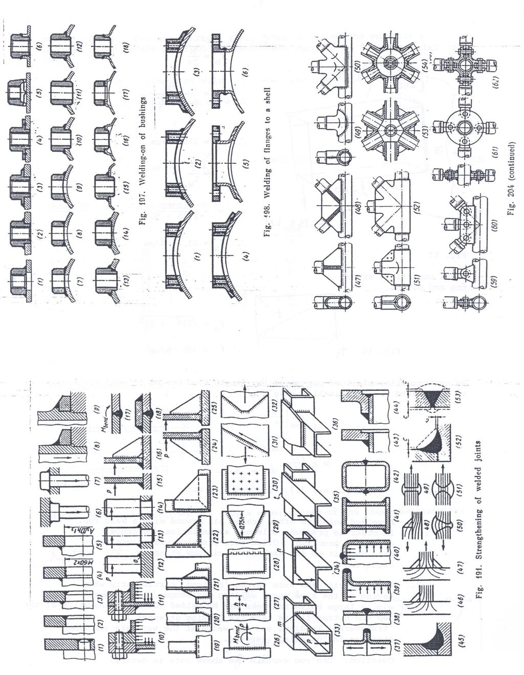
9 As mentioned on p3 (ig 4) an AWS rule is that if any component on any part of a eld outline is loaded in parallel; then the hole eld is to be analysed as if it is all in parallel. Obviously if it ere orth the time, at the cost of an engineer s rate of pay, adjustments could be done for different part of a eld and the fillets could be tapered from point to point. It all could be quite aesthetically pleasing. Specific application of elding. There are many applications of elding such as pressure vessels, pipe ork, bridges and many others, hich are covered by particular codes. Take care to make yourself aare of them and adhere to them. The procedure examined here may be used for machine frames and similar mechanical applications. Welding typical involves human judgement to a greater degree than most other machine operations. As a consequence there are precautions taken in important jobs that are not often seen in other operations. To ensure a high degree of safety it may be orth considering the use of more than one joint to carry an significant load, instead of applying a large actor of Safety to a single joint. ig 11 At right shos some of the undesirable realities of elded joint that may go undetected. ig 12 belo shos one of the reasons that hen a joint fails it is usually not the eld deposit that fails. The penetration has provided a greater deposit than alloed for in the calcs. Weld deposit Inclusions Heat effected zone Undercut Incomplete penetration ig 13 Left and belo. These figures from Reshtov give an indication of the stress concentration that takes place in ide range of elded joints. Normal and shear stresses are shon together ith the effect of partial and full eld penetration. 9
10 Modes of eld analysis. 1 Analyse the eld as described here or in more detail. Try alternate eld outlines to arrive at a preferable eld hich has some clear advantages eg length, eight, least preparation. A programmable CAD system could moderately easily be used to automate the analysis. 2 Design a structure so that its components can carry their loads. Then eld all around the joins to the depth of the all of the components. Do not analyse the elds. All around elds are employed in many situation to seal the joining faces from corrosion or other intrusions. 3 Use a EA method of analysis. Prescribe elds at joints to the depth and idth that they loer stresses in their neighbours belo safe limits. Some Precautions 1 Every joint generates some stress concentration. A ell prepared butt joint that is machined flat after elding may cause the least, but it too may raise the stresses by at least 10%. 2 Plate or sections joined together should not vary in thickness by more than about 50%. If the elder is suitably experienced a larger difference may be used, but it is better to have section that provides for a transition in thickness. This is indicated by the 2 figures belo: ig 14. Indications of limits in disparity in thicknesses 3 When designing a elded joint that has to be relatively stiff under load or has to be relatively safe against failure, reinforce the joint ith plates and other section to spread the load into a larger portion of the parent materials. Examples of this are shon on page 11: a igs 1 to 5 sho ho an end flange on a shaft is reinforced ith larger and double elds figs 2 & 3, And by a scre thread and an interference fit in figs 4 & 5. b A tensioned component in fig 6 is trapped by a shoulder in 7, and by a eb in compression in 24 to 25. c The loads are spread at the joint in figs 19 to 23, and in 26 to 30, again in figs 33 to
11 11
12 ig 15 A preliminary spreadsheet developed to solve for the eld idth of the example shon on ig 8. Be arned that this spreadsheet has not been checked and it almost certainly contains faults. 12
EDEXCEL NATIONAL CERTIFICATE/DIPLOMA MECHANICAL PRINCIPLES AND APPLICATIONS NQF LEVEL 3 OUTCOME 1 - LOADING SYSTEMS TUTORIAL 3 LOADED COMPONENTS
 EDEXCEL NATIONAL CERTIICATE/DIPLOMA MECHANICAL PRINCIPLES AND APPLICATIONS NQ LEVEL 3 OUTCOME 1 - LOADING SYSTEMS TUTORIAL 3 LOADED COMPONENTS 1. Be able to determine the effects of loading in static engineering
Module 11 Design of Joints for Special Loading. Version 2 ME, IIT Kharagpur
 Module 11 Design of Joints for Special Loading Version ME, IIT Kharagpur Lesson Design of Eccentrically Loaded Welded Joints Version ME, IIT Kharagpur Instructional Objectives: At the end of this lesson,
Mechanical Engineering Ph.D. Preliminary Qualifying Examination Solid Mechanics February 25, 2002
 student personal identification (ID) number on each sheet. Do not write your name on any sheet. #1. A homogeneous, isotropic, linear elastic bar has rectangular cross sectional area A, modulus of elasticity
Tuesday, February 11, Chapter 3. Load and Stress Analysis. Dr. Mohammad Suliman Abuhaiba, PE
 1 Chapter 3 Load and Stress Analysis 2 Chapter Outline Equilibrium & Free-Body Diagrams Shear Force and Bending Moments in Beams Singularity Functions Stress Cartesian Stress Components Mohr s Circle for
Downloaded from Downloaded from / 1
 PURWANCHAL UNIVERSITY III SEMESTER FINAL EXAMINATION-2002 LEVEL : B. E. (Civil) SUBJECT: BEG256CI, Strength of Material Full Marks: 80 TIME: 03:00 hrs Pass marks: 32 Candidates are required to give their
and F NAME: ME rd Sample Final Exam PROBLEM 1 (25 points) Prob. 1 questions are all or nothing. PROBLEM 1A. (5 points)
 Prob. 1 questions are all or nothing. PROBLEM 1A. (5 points)") ME 270 3 rd Sample inal Exam PROBLEM 1 (25 points) Prob. 1 questions are all or nothing. PROBLEM 1A. (5 points) IND: In your own words, please state Newton s Laws: 1 st Law = 2 nd Law = 3 rd Law = PROBLEM
ME 270 3 rd Sample inal Exam PROBLEM 1 (25 points) Prob. 1 questions are all or nothing. PROBLEM 1A. (5 points) IND: In your own words, please state Newton s Laws: 1 st Law = 2 nd Law = 3 rd Law = PROBLEM
Name (Print) ME Mechanics of Materials Exam # 3 Date: December 9, 2013 Time: 7:00 9:00 PM Location: EE 129 & EE170
 ME Mechanics of Materials Exam # 3 Date: December 9, 2013 Time: 7:00 9:00 PM Location: EE 129 & EE170") Name (Print) (Last) (First) Instructions: ME 323 - Mechanics of Materials Exam # 3 Date: December 9, 2013 Time: 7:00 9:00 PM Location: EE 129 & EE170 Circle your lecturer s name and your class meeting
Name (Print) (Last) (First) Instructions: ME 323 - Mechanics of Materials Exam # 3 Date: December 9, 2013 Time: 7:00 9:00 PM Location: EE 129 & EE170 Circle your lecturer s name and your class meeting
COURSE TITLE : APPLIED MECHANICS & STRENGTH OF MATERIALS COURSE CODE : 4017 COURSE CATEGORY : A PERIODS/WEEK : 6 PERIODS/ SEMESTER : 108 CREDITS : 5
 COURSE TITLE : APPLIED MECHANICS & STRENGTH OF MATERIALS COURSE CODE : 4017 COURSE CATEGORY : A PERIODS/WEEK : 6 PERIODS/ SEMESTER : 108 CREDITS : 5 TIME SCHEDULE MODULE TOPICS PERIODS 1 Simple stresses
Stress Analysis Lecture 3 ME 276 Spring Dr./ Ahmed Mohamed Nagib Elmekawy
 Stress Analysis Lecture 3 ME 276 Spring 2017-2018 Dr./ Ahmed Mohamed Nagib Elmekawy Axial Stress 2 Beam under the action of two tensile forces 3 Beam under the action of two tensile forces 4 Shear Stress
D e s i g n o f R i v e t e d J o i n t s, C o t t e r & K n u c k l e J o i n t s
 D e s i g n o f R i v e t e d J o i n t s, C o t t e r & K n u c k l e J o i n t s 1. Design of various types of riveted joints under different static loading conditions, eccentrically loaded riveted joints.
University of Waterloo. Partial notes Part 6 (Welded Joints) Fall 2005
 Fall 2005") University of Waterloo Department of Mechanical Engineering ME 3 - Mechanical Design 1 artial notes art 6 (Welded Joints) (G. Glinka) Fall 005 1. Introduction to the Static Strength Analysis of Welded
University of Waterloo Department of Mechanical Engineering ME 3 - Mechanical Design 1 artial notes art 6 (Welded Joints) (G. Glinka) Fall 005 1. Introduction to the Static Strength Analysis of Welded
: APPLIED MECHANICS & STRENGTH OF MATERIALS COURSE CODE : 4021 COURSE CATEGORY : A PERIODS/ WEEK : 5 PERIODS/ SEMESTER : 75 CREDIT : 5 TIME SCHEDULE
 COURSE TITLE : APPLIED MECHANICS & STRENGTH OF MATERIALS COURSE CODE : 4021 COURSE CATEGORY : A PERIODS/ WEEK : 5 PERIODS/ SEMESTER : 75 CREDIT : 5 TIME SCHEDULE MODULE TOPIC PERIODS 1 Simple stresses
Structural Analysis I Chapter 4 - Torsion TORSION
 ORSION orsional stress results from the action of torsional or twisting moments acting about the longitudinal axis of a shaft. he effect of the application of a torsional moment, combined with appropriate
ME Final Exam. PROBLEM NO. 4 Part A (2 points max.) M (x) y. z (neutral axis) beam cross-sec+on. 20 kip ft. 0.2 ft. 10 ft. 0.1 ft.
 M (x) y. z (neutral axis) beam cross-sec+on. 20 kip ft. 0.2 ft. 10 ft. 0.1 ft.") ME 323 - Final Exam Name December 15, 2015 Instructor (circle) PROEM NO. 4 Part A (2 points max.) Krousgrill 11:30AM-12:20PM Ghosh 2:30-3:20PM Gonzalez 12:30-1:20PM Zhao 4:30-5:20PM M (x) y 20 kip ft 0.2
ME 323 - Final Exam Name December 15, 2015 Instructor (circle) PROEM NO. 4 Part A (2 points max.) Krousgrill 11:30AM-12:20PM Ghosh 2:30-3:20PM Gonzalez 12:30-1:20PM Zhao 4:30-5:20PM M (x) y 20 kip ft 0.2
Engineering Science OUTCOME 1 - TUTORIAL 4 COLUMNS
 Unit 2: Unit code: QCF Level: Credit value: 15 Engineering Science L/601/10 OUTCOME 1 - TUTORIAL COLUMNS 1. Be able to determine the behavioural characteristics of elements of static engineering systems
R13. II B. Tech I Semester Regular Examinations, Jan MECHANICS OF SOLIDS (Com. to ME, AME, AE, MTE) PART-A
 PART-A") SET - 1 II B. Tech I Semester Regular Examinations, Jan - 2015 MECHANICS OF SOLIDS (Com. to ME, AME, AE, MTE) Time: 3 hours Max. Marks: 70 Note: 1. Question Paper consists of two parts (Part-A and Part-B)
SET - 1 II B. Tech I Semester Regular Examinations, Jan - 2015 MECHANICS OF SOLIDS (Com. to ME, AME, AE, MTE) Time: 3 hours Max. Marks: 70 Note: 1. Question Paper consists of two parts (Part-A and Part-B)
Advanced Structural Analysis EGF Section Properties and Bending
 Advanced Structural Analysis EGF316 3. Section Properties and Bending 3.1 Loads in beams When we analyse beams, we need to consider various types of loads acting on them, for example, axial forces, shear
MAAE 2202 A. Come to the PASS workshop with your mock exam complete. During the workshop you can work with other students to review your work.
 It is most beneficial to you to write this mock final exam UNDER EXAM CONDITIONS. This means: Complete the exam in 3 hours. Work on your own. Keep your textbook closed. Attempt every question. After the
OUTCOME 1 - TUTORIAL 3 BENDING MOMENTS. You should judge your progress by completing the self assessment exercises. CONTENTS
 Unit 2: Unit code: QCF Level: 4 Credit value: 15 Engineering Science L/601/1404 OUTCOME 1 - TUTORIAL 3 BENDING MOMENTS 1. Be able to determine the behavioural characteristics of elements of static engineering
MECHANICS OF MATERIALS
 2009 The McGraw-Hill Companies, Inc. All rights reserved. Fifth SI Edition CHAPTER 3 MECHANICS OF MATERIALS Ferdinand P. Beer E. Russell Johnston, Jr. John T. DeWolf David F. Mazurek Torsion Lecture Notes:
PDDC 1 st Semester Civil Engineering Department Assignments of Mechanics of Solids [ ] Introduction, Fundamentals of Statics
![PDDC 1 st Semester Civil Engineering Department Assignments of Mechanics of Solids [ ] Introduction, Fundamentals of Statics](/thumbs/92/109382806.jpg "PDDC 1 st Semester Civil Engineering Department Assignments of Mechanics of Solids [ ] Introduction, Fundamentals of Statics") Page1 PDDC 1 st Semester Civil Engineering Department Assignments of Mechanics of Solids [2910601] Introduction, Fundamentals of Statics 1. Differentiate between Scalar and Vector quantity. Write S.I.
Page1 PDDC 1 st Semester Civil Engineering Department Assignments of Mechanics of Solids [2910601] Introduction, Fundamentals of Statics 1. Differentiate between Scalar and Vector quantity. Write S.I.
Riveted Joints and Linear Buckling in the Steel Load-bearing Structure
 American Journal of Mechanical Engineering, 017, Vol. 5, No. 6, 39-333 Availale online at http://pus.sciepu.com/ajme/5/6/0 Science and Education Pulishing DOI:10.1691/ajme-5-6-0 Riveted Joints and Linear
2. (a) Explain different types of wing structures. (b) Explain the advantages and disadvantages of different materials used for aircraft
 Explain different types of wing structures. (b) Explain the advantages and disadvantages of different materials used for aircraft") Code No: 07A62102 R07 Set No. 2 III B.Tech II Semester Regular/Supplementary Examinations,May 2010 Aerospace Vehicle Structures -II Aeronautical Engineering Time: 3 hours Max Marks: 80 Answer any FIVE
Code No: 07A62102 R07 Set No. 2 III B.Tech II Semester Regular/Supplementary Examinations,May 2010 Aerospace Vehicle Structures -II Aeronautical Engineering Time: 3 hours Max Marks: 80 Answer any FIVE
NAME: Given Formulae: Law of Cosines: Law of Sines:
 NME: Given Formulae: Law of Cosines: EXM 3 PST PROBLEMS (LESSONS 21 TO 28) 100 points Thursday, November 16, 2017, 7pm to 9:30, Room 200 You are allowed to use a calculator and drawing equipment, only.
ME311 Machine Design
 ME311 Machine Design Lecture : Materials; Stress & Strain; Power Transmission W Dornfeld 13Sep018 airfield University School of Engineering Stress-Strain Curve for Ductile Material Ultimate Tensile racture
STRESS STRAIN AND DEFORMATION OF SOLIDS, STATES OF STRESS
 1 UNIT I STRESS STRAIN AND DEFORMATION OF SOLIDS, STATES OF STRESS 1. Define: Stress When an external force acts on a body, it undergoes deformation. At the same time the body resists deformation. The
Determine the resultant internal loadings acting on the cross section at C of the beam shown in Fig. 1 4a.
 E X M P L E 1.1 Determine the resultant internal loadings acting on the cross section at of the beam shown in Fig. 1 a. 70 N/m m 6 m Fig. 1 Support Reactions. This problem can be solved in the most direct
Definition of a new Parameter for use in Active Structural Acoustic Control
 Definition of a ne Parameter for use in Active Structural Acoustic Control Brigham Young University Abstract-- A ne parameter as recently developed by Jeffery M. Fisher (M.S.) for use in Active Structural
Design of Steel Structures Dr. Damodar Maity Department of Civil Engineering Indian Institute of Technology, Guwahati
 Design of Steel Structures Dr. Damodar Maity Department of Civil Engineering Indian Institute of Technology, Guwahati Module - 7 Gantry Girders and Plate Girders Lecture - 4 Introduction to Plate Girders
QUESTION BANK SEMESTER: III SUBJECT NAME: MECHANICS OF SOLIDS
 QUESTION BANK SEMESTER: III SUBJECT NAME: MECHANICS OF SOLIDS UNIT 1- STRESS AND STRAIN PART A (2 Marks) 1. Define longitudinal strain and lateral strain. 2. State Hooke s law. 3. Define modular ratio,
Stress Analysis Lecture 4 ME 276 Spring Dr./ Ahmed Mohamed Nagib Elmekawy
 Stress Analysis Lecture 4 ME 76 Spring 017-018 Dr./ Ahmed Mohamed Nagib Elmekawy Shear and Moment Diagrams Beam Sign Convention The positive directions are as follows: The internal shear force causes a
KINGS COLLEGE OF ENGINEERING DEPARTMENT OF MECHANICAL ENGINEERING QUESTION BANK. Subject code/name: ME2254/STRENGTH OF MATERIALS Year/Sem:II / IV
 KINGS COLLEGE OF ENGINEERING DEPARTMENT OF MECHANICAL ENGINEERING QUESTION BANK Subject code/name: ME2254/STRENGTH OF MATERIALS Year/Sem:II / IV UNIT I STRESS, STRAIN DEFORMATION OF SOLIDS PART A (2 MARKS)
2. Polar moment of inertia As stated above, the polar second moment of area, J is defined as. Sample copy
 GATE PATHSHALA - 91. Polar moment of inertia As stated above, the polar second moment of area, is defined as z π r dr 0 R r π R π D For a solid shaft π (6) QP 0 π d Solid shaft π d Hollow shaft, " ( do
PES Institute of Technology
 PES Institute of Technology Bangalore south campus, Bangalore-5460100 Department of Mechanical Engineering Faculty name : Madhu M Date: 29/06/2012 SEM : 3 rd A SEC Subject : MECHANICS OF MATERIALS Subject
Module 6. Approximate Methods for Indeterminate Structural Analysis. Version 2 CE IIT, Kharagpur
 Module 6 Approximate Methods for Indeterminate Structural Analysis Lesson 35 Indeterminate Trusses and Industrial rames Instructional Objectives: After reading this chapter the student will be able to
8.3 Design of Base Plate for Thickness
 8.3 Design o Base Plate or Thickness 8.3.1 Design o base plate or thickness (Elastic Design) Upto this point, the chie concern has been about the concrete oundation, and methods o design have been proposed
CHAPTER 4. Stresses in Beams
 CHAPTER 4 Stresses in Beams Problem 1. A rolled steel joint (RSJ) of -section has top and bottom flanges 150 mm 5 mm and web of size 00 mm 1 mm. t is used as a simply supported beam over a span of 4 m
ENGINEERING SCIENCE H1 OUTCOME 1 - TUTORIAL 4 COLUMNS EDEXCEL HNC/D ENGINEERING SCIENCE LEVEL 4 H1 FORMERLY UNIT 21718P
 ENGINEERING SCIENCE H1 OUTCOME 1 - TUTORIAL COLUMNS EDEXCEL HNC/D ENGINEERING SCIENCE LEVEL H1 FORMERLY UNIT 21718P This material is duplicated in the Mechanical Principles module H2 and those studying
QUESTION BANK DEPARTMENT: CIVIL SEMESTER: III SUBJECT CODE: CE2201 SUBJECT NAME: MECHANICS OF SOLIDS UNIT 1- STRESS AND STRAIN PART A
 DEPARTMENT: CIVIL SUBJECT CODE: CE2201 QUESTION BANK SEMESTER: III SUBJECT NAME: MECHANICS OF SOLIDS UNIT 1- STRESS AND STRAIN PART A (2 Marks) 1. Define longitudinal strain and lateral strain. 2. State
Chapter 3. Load and Stress Analysis. Lecture Slides
 Lecture Slides Chapter 3 Load and Stress Analysis 2015 by McGraw Hill Education. This is proprietary material solely for authorized instructor use. Not authorized for sale or distribution in any manner.
Arberi Ferraj. Wentworth Institute of Technology. Design of Machine Elements MECH 420
 P a g e 1 Arberi Ferraj Wentworth Institute of Technology Design of Machine Elements MECH 420 P a g e 2 1. Executive Summary A scissor car jack was designed and must be reverse-engineered in order to discover
Aluminum shell. Brass core. 40 in
 PROBLEM #1 (22 points) A solid brass core is connected to a hollow rod made of aluminum. Both are attached at each end to a rigid plate as shown in Fig. 1. The moduli of aluminum and brass are EA=11,000
MECE 3321 MECHANICS OF SOLIDS CHAPTER 1
 MECE 3321 MECHANICS O SOLIDS CHAPTER 1 Samantha Ramirez, MSE WHAT IS MECHANICS O MATERIALS? Rigid Bodies Statics Dynamics Mechanics Deformable Bodies Solids/Mech. Of Materials luids 1 WHAT IS MECHANICS
2012 MECHANICS OF SOLIDS
 R10 SET - 1 II B.Tech II Semester, Regular Examinations, April 2012 MECHANICS OF SOLIDS (Com. to ME, AME, MM) Time: 3 hours Max. Marks: 75 Answer any FIVE Questions All Questions carry Equal Marks ~~~~~~~~~~~~~~~~~~~~~~
Accordingly, the nominal section strength [resistance] for initiation of yielding is calculated by using Equation C-C3.1.
![Accordingly, the nominal section strength [resistance] for initiation of yielding is calculated by using Equation C-C3.1.](/thumbs/89/98617066.jpg "Accordingly, the nominal section strength [resistance] for initiation of yielding is calculated by using Equation C-C3.1.") C3 Flexural Members C3.1 Bending The nominal flexural strength [moment resistance], Mn, shall be the smallest of the values calculated for the limit states of yielding, lateral-torsional buckling and distortional
C3 Flexural Members C3.1 Bending The nominal flexural strength [moment resistance], Mn, shall be the smallest of the values calculated for the limit states of yielding, lateral-torsional buckling and distortional
PROBLEM 7.1 SOLUTION. σ = 5.49 ksi. τ = ksi
 PROBLEM 7.1 For the given state of stress, determine the normal and shearing stresses exerted on the oblique face of the shaded triangular element shon. Use a method of analysis based on the equilibrium
Design of Steel Structures Prof. Damodar Maity Department of Civil Engineering Indian Institute of Technology, Guwahati
 Design of Steel Structures Prof. Damodar Maity Department of Civil Engineering Indian Institute of Technology, Guwahati Module 7 Gantry Girders and Plate Girders Lecture - 3 Introduction to Plate girders
(48) CHAPTER 3: TORSION
 CHAPTER 3: TORSION") (48) CHAPTER 3: TORSION Introduction: In this chapter structural members and machine parts that are in torsion will be considered. More specifically, you will analyze the stresses and strains in members
(48) CHAPTER 3: TORSION Introduction: In this chapter structural members and machine parts that are in torsion will be considered. More specifically, you will analyze the stresses and strains in members
4. SHAFTS. A shaft is an element used to transmit power and torque, and it can support
 4. SHAFTS A shaft is an element used to transmit power and torque, and it can support reverse bending (fatigue). Most shafts have circular cross sections, either solid or tubular. The difference between
EMA 3702 Mechanics & Materials Science (Mechanics of Materials) Chapter 3 Torsion
 Chapter 3 Torsion") EMA 3702 Mechanics & Materials Science (Mechanics of Materials) Chapter 3 Torsion Introduction Stress and strain in components subjected to torque T Circular Cross-section shape Material Shaft design Non-circular
EMA 3702 Mechanics & Materials Science (Mechanics of Materials) Chapter 3 Torsion Introduction Stress and strain in components subjected to torque T Circular Cross-section shape Material Shaft design Non-circular
ENT345 Mechanical Components Design
 1) LOAD AND STRESS ANALYSIS i. Principle stress ii. The maximum shear stress iii. The endurance strength of shaft. 1) Problem 3-71 A countershaft carrying two-v belt pulleys is shown in the figure. Pulley
Members Subjected to Torsional Loads
 Members Subjected to Torsional Loads Torsion of circular shafts Definition of Torsion: Consider a shaft rigidly clamped at one end and twisted at the other end by a torque T = F.d applied in a plane perpendicular
UNIT- I Thin plate theory, Structural Instability:
 UNIT- I Thin plate theory, Structural Instability: Analysis of thin rectangular plates subject to bending, twisting, distributed transverse load, combined bending and in-plane loading Thin plates having
Engineering Mechanics Department of Mechanical Engineering Dr. G. Saravana Kumar Indian Institute of Technology, Guwahati
 Engineering Mechanics Department of Mechanical Engineering Dr. G. Saravana Kumar Indian Institute of Technology, Guwahati Module 3 Lecture 6 Internal Forces Today, we will see analysis of structures part
STRUCTURAL SURFACES & FLOOR GRILLAGES
 STRUCTURAL SURFACES & FLOOR GRILLAGES INTRODUCTION Integral car bodies are 3D structures largely composed of approximately subassemblies- SSS Planar structural subassemblies can be grouped into two categories
Chapter 3. Load and Stress Analysis
 Chapter 3 Load and Stress Analysis 2 Shear Force and Bending Moments in Beams Internal shear force V & bending moment M must ensure equilibrium Fig. 3 2 Sign Conventions for Bending and Shear Fig. 3 3
7.6 Stress in symmetrical elastic beam transmitting both shear force and bending moment
 7.6 Stress in symmetrical elastic beam transmitting both shear force and bending moment à It is more difficult to obtain an exact solution to this problem since the presence of the shear force means that
ENGINEERING COUNCIL DIPLOMA LEVEL MECHANICS OF SOLIDS D209 TUTORIAL 3 - SHEAR FORCE AND BENDING MOMENTS IN BEAMS
 ENGINEERING COUNCIL DIPLOMA LEVEL MECHANICS OF SOLIDS D209 TUTORIAL 3 - SHEAR FORCE AND BENDING MOMENTS IN BEAMS You should judge your progress by completing the self assessment exercises. On completion
CONNECTION DESIGN. Connections must be designed at the strength limit state
 CONNECTION DESIGN Connections must be designed at the strength limit state Average of the factored force effect at the connection and the force effect in the member at the same point At least 75% of the
UNIT 1 STRESS STRAIN AND DEFORMATION OF SOLIDS, STATES OF STRESS 1. Define stress. When an external force acts on a body, it undergoes deformation.
 UNIT 1 STRESS STRAIN AND DEFORMATION OF SOLIDS, STATES OF STRESS 1. Define stress. When an external force acts on a body, it undergoes deformation. At the same time the body resists deformation. The magnitude
7.3 Design of members subjected to combined forces
 7.3 Design of members subjected to combined forces 7.3.1 General In the previous chapters of Draft IS: 800 LSM version, we have stipulated the codal provisions for determining the stress distribution in
Group-invariant solutions of nonlinear elastodynamic problems of plates and shells *
 Group-invariant solutions of nonlinear elastodynamic problems of plates and shells * V. A. Dzhupanov, V. M. Vassilev, P. A. Dzhondzhorov Institute of mechanics, Bulgarian Academy of Sciences, Acad. G.
ME 202 STRENGTH OF MATERIALS SPRING 2014 HOMEWORK 4 SOLUTIONS
 ÇANKAYA UNIVERSITY MECHANICAL ENGINEERING DEPARTMENT ME 202 STRENGTH OF MATERIALS SPRING 2014 Due Date: 1 ST Lecture Hour of Week 12 (02 May 2014) Quiz Date: 3 rd Lecture Hour of Week 12 (08 May 2014)
Levers. 558 A Textbook of Machine Design
 558 A Textbook of Machine Design C H A P T E R 15 Levers 1. Introduction.. Application of Levers in Engineering Practice.. Design of a Lever. 4. Hand Lever. 5. Foot Lever. 6. Cranked Lever. 7. Lever for
Structural Steelwork Eurocodes Development of a Trans-National Approach
 Course: Eurocode 4 Structural Steelwork Eurocodes Development of a Trans-National Approach Lecture 9 : Composite joints Annex B References: COST C1: Composite steel-concrete joints in frames for buildings:
PERIYAR CENTENARY POLYTECHNIC COLLEGE PERIYAR NAGAR - VALLAM THANJAVUR. DEPARTMENT OF MECHANICAL ENGINEERING QUESTION BANK
 PERIYAR CENTENARY POLYTECHNIC COLLEGE PERIYAR NAGAR - VALLAM - 613 403 - THANJAVUR. DEPARTMENT OF MECHANICAL ENGINEERING QUESTION BANK Sub : Strength of Materials Year / Sem: II / III Sub Code : MEB 310
Design of Steel Structures Dr. Damodar Maity Department of Civil Engineering Indian Institute of Technology, Guwahati
 Design of Steel Structures Dr. Damodar Maity Department of Civil Engineering Indian Institute of Technology, Guwahati Module - 6 Flexural Members Lecture 5 Hello today I am going to deliver the lecture
Unit III Theory of columns. Dr.P.Venkateswara Rao, Associate Professor, Dept. of Civil Engg., SVCE, Sriperumbudir
 Unit III Theory of columns 1 Unit III Theory of Columns References: Punmia B.C.,"Theory of Structures" (SMTS) Vol II, Laxmi Publishing Pvt Ltd, New Delhi 2004. Rattan.S.S., "Strength of Materials", Tata
International Institute of Welding A world of joining experience
 International Institute of Welding A orld of joining eperience XV- 105-06, XV-F-74-06 Special cases of the calculation of residual elding distortions J. Farkas K. Jármai University of Miskolc, Hungary
INSTITUTE OF AERONAUTICAL ENGINEERING (Autonomous) Dundigal, Hyderabad
 Dundigal, Hyderabad") INSTITUTE OF AERONAUTICAL ENGINEERING (Autonomous) Dundigal, Hyderabad -00 04 CIVIL ENGINEERING QUESTION BANK Course Name : STRENGTH OF MATERIALS II Course Code : A404 Class : II B. Tech II Semester Section
INSTITUTE OF AERONAUTICAL ENGINEERING (Autonomous) Dundigal, Hyderabad -00 04 CIVIL ENGINEERING QUESTION BANK Course Name : STRENGTH OF MATERIALS II Course Code : A404 Class : II B. Tech II Semester Section
Improvement in Design & Development of Multi-Spindle Drilling Head Machine
 Improvement in Design & Development of Multi-Spindle Drilling Head Machine Prof. Vivek I. Akolkar 1, Prof. Vikas I. Somankar 2, Prof. M. M. Patil 3 1,2 Assistant Professor, Department of Mechanical Engineering,
Initial Stress Calculations
 Initial Stress Calculations The following are the initial hand stress calculations conducted during the early stages of the design process. Therefore, some of the material properties as well as dimensions
Mechanics of Materials
 Mechanics of Materials 2. Introduction Dr. Rami Zakaria References: 1. Engineering Mechanics: Statics, R.C. Hibbeler, 12 th ed, Pearson 2. Mechanics of Materials: R.C. Hibbeler, 9 th ed, Pearson 3. Mechanics
PLATE GIRDERS II. Load. Web plate Welds A Longitudinal elevation. Fig. 1 A typical Plate Girder
 16 PLATE GIRDERS II 1.0 INTRODUCTION This chapter describes the current practice for the design of plate girders adopting meaningful simplifications of the equations derived in the chapter on Plate Girders
CHAPTER 4: BENDING OF BEAMS
 (74) CHAPTER 4: BENDING OF BEAMS This chapter will be devoted to the analysis of prismatic members subjected to equal and opposite couples M and M' acting in the same longitudinal plane. Such members are
IDE 110 Mechanics of Materials Spring 2006 Final Examination FOR GRADING ONLY
 Spring 2006 Final Examination STUDENT S NAME (please print) STUDENT S SIGNATURE STUDENT NUMBER IDE 110 CLASS SECTION INSTRUCTOR S NAME Do not turn this page until instructed to start. Write your name on
JUT!SI I I I TO BE RETURNED AT THE END OF EXAMINATION. THIS PAPER MUST NOT BE REMOVED FROM THE EXAM CENTRE. SURNAME: FIRST NAME: STUDENT NUMBER:
 JUT!SI I I I TO BE RETURNED AT THE END OF EXAMINATION. THIS PAPER MUST NOT BE REMOVED FROM THE EXAM CENTRE. SURNAME: FIRST NAME: STUDENT NUMBER: COURSE: Tutor's name: Tutorial class day & time: SPRING
Name (Print) ME Mechanics of Materials Exam # 1 Date: October 5, 2016 Time: 8:00 10:00 PM
 ME Mechanics of Materials Exam # 1 Date: October 5, 2016 Time: 8:00 10:00 PM") Name (Print) (Last) (First) Instructions: ME 323 - Mechanics of Materials Exam # 1 Date: October 5, 2016 Time: 8:00 10:00 PM Circle your lecturer s name and your class meeting time. Gonzalez Krousgrill
Name (Print) (Last) (First) Instructions: ME 323 - Mechanics of Materials Exam # 1 Date: October 5, 2016 Time: 8:00 10:00 PM Circle your lecturer s name and your class meeting time. Gonzalez Krousgrill
3 Hours/100 Marks Seat No.
 *17304* 17304 14115 3 Hours/100 Marks Seat No. Instructions : (1) All questions are compulsory. (2) Illustrate your answers with neat sketches wherever necessary. (3) Figures to the right indicate full
C100 Cryomodule Vacuum Vessel Structural Analysis An Addendum to JLAB-TN
 Introduction C100 Cryomodule Vacuum Vessel Structural Analysis An Addendum to JLAB-TN-07-081 Gary G. Cheng and Edward F. Daly The C100 cryomodule (CM) vacuum vessel structural analysis per ASME Boiler
SRI CHANDRASEKHARENDRA SARASWATHI VISWA MAHAVIDHYALAYA
 SRI CHANDRASEKHARENDRA SARASWATHI VISWA MAHAVIDHYALAYA (Declared as Deemed-to-be University under Section 3 of the UGC Act, 1956, Vide notification No.F.9.9/92-U-3 dated 26 th May 1993 of the Govt. of
BE Semester- I ( ) Question Bank (MECHANICS OF SOLIDS)
 Question Bank (MECHANICS OF SOLIDS)") BE Semester- I ( ) Question Bank (MECHANICS OF SOLIDS) All questions carry equal marks(10 marks) Q.1 (a) Write the SI units of following quantities and also mention whether it is scalar or vector: (i)
BE Semester- I ( ) Question Bank (MECHANICS OF SOLIDS) All questions carry equal marks(10 marks) Q.1 (a) Write the SI units of following quantities and also mention whether it is scalar or vector: (i)
NORMAL STRESS. The simplest form of stress is normal stress/direct stress, which is the stress perpendicular to the surface on which it acts.
 NORMAL STRESS The simplest form of stress is normal stress/direct stress, which is the stress perpendicular to the surface on which it acts. σ = force/area = P/A where σ = the normal stress P = the centric
DESIGN AND DETAILING OF COUNTERFORT RETAINING WALL
 DESIGN AND DETAILING OF COUNTERFORT RETAINING WALL When the height of the retaining wall exceeds about 6 m, the thickness of the stem and heel slab works out to be sufficiently large and the design becomes
C100 Cryomodule Vacuum Vessel Structural Analysis Gary G. Cheng, William R. Hicks, and Edward F. Daly
 Introduction C100 Cryomodule Vacuum Vessel Structural Analysis Gary G. Cheng, William R. Hicks, and Edward F. Daly Cryomodule (CM) prototypes for CEBAF 12GeV upgrade project have been built in the past
and sinθ = cosb =, and we know a and b are acute angles, find cos( a+ b) Trigonometry Topics Accuplacer Review revised July 2016 sin.
 Trigonometry Topics Accuplacer Review revised July 2016 sin.") Trigonometry Topics Accuplacer Revie revised July 0 You ill not be alloed to use a calculator on the Accuplacer Trigonometry test For more information, see the JCCC Testing Services ebsite at http://jcccedu/testing/
Trigonometry Topics Accuplacer Revie revised July 0 You ill not be alloed to use a calculator on the Accuplacer Trigonometry test For more information, see the JCCC Testing Services ebsite at http://jcccedu/testing/
Module 7 Design of Springs. Version 2 ME, IIT Kharagpur
 Module 7 Design of Springs Lesson 1 Introduction to Design of Helical Springs Instructional Objectives: At the end of this lesson, the students should be able to understand: Uses of springs Nomenclature
Mechanical Design in Optical Engineering
 Torsion Torsion: Torsion refers to the twisting of a structural member that is loaded by couples (torque) that produce rotation about the member s longitudinal axis. In other words, the member is loaded
3. BEAMS: STRAIN, STRESS, DEFLECTIONS
 3. BEAMS: STRAIN, STRESS, DEFLECTIONS The beam, or flexural member, is frequently encountered in structures and machines, and its elementary stress analysis constitutes one of the more interesting facets
Mechanics of Solids. Mechanics Of Solids. Suraj kr. Ray Department of Civil Engineering
 Mechanics Of Solids Suraj kr. Ray (surajjj2445@gmail.com) Department of Civil Engineering 1 Mechanics of Solids is a branch of applied mechanics that deals with the behaviour of solid bodies subjected
Chapter 5 Torsion STRUCTURAL MECHANICS: CE203. Notes are based on Mechanics of Materials: by R. C. Hibbeler, 7th Edition, Pearson
 STRUCTURAL MECHANICS: CE203 Chapter 5 Torsion Notes are based on Mechanics of Materials: by R. C. Hibbeler, 7th Edition, Pearson Dr B. Achour & Dr Eng. K. El-kashif Civil Engineering Department, University
10/14/2011. Types of Shear Failure. CASE 1: a v /d 6. a v. CASE 2: 2 a v /d 6. CASE 3: a v /d 2
 V V Types o Shear Failure a v CASE 1: a v /d 6 d V a v CASE 2: 2 a v /d 6 d V a v CASE 3: a v /d 2 d V 1 Shear Resistance Concrete compression d V cz = Shear orce in the compression zone (20 40%) V a =
2014 MECHANICS OF MATERIALS
 R10 SET - 1 II. Tech I Semester Regular Examinations, March 2014 MEHNIS OF MTERILS (ivil Engineering) Time: 3 hours Max. Marks: 75 nswer any FIVE Questions ll Questions carry Equal Marks ~~~~~~~~~~~~~~~~~~~~~~~~~
CHAPTER 2 Failure/Fracture Criterion
 (11) CHAPTER 2 Failure/Fracture Criterion (12) Failure (Yield) Criteria for Ductile Materials under Plane Stress Designer engineer: 1- Analysis of loading (for simple geometry using what you learn here
Problem d d d B C E D. 0.8d. Additional lecturebook examples 29 ME 323
 Problem 9.1 Two beam segments, AC and CD, are connected together at C by a frictionless pin. Segment CD is cantilevered from a rigid support at D, and segment AC has a roller support at A. a) Determine
Chapter 5: Torsion. 1. Torsional Deformation of a Circular Shaft 2. The Torsion Formula 3. Power Transmission 4. Angle of Twist CHAPTER OBJECTIVES
 CHAPTER OBJECTIVES Chapter 5: Torsion Discuss effects of applying torsional loading to a long straight member (shaft or tube) Determine stress distribution within the member under torsional load Determine
STRESS. Bar. ! Stress. ! Average Normal Stress in an Axially Loaded. ! Average Shear Stress. ! Allowable Stress. ! Design of Simple Connections
 STRESS! Stress Evisdom! verage Normal Stress in an xially Loaded ar! verage Shear Stress! llowable Stress! Design of Simple onnections 1 Equilibrium of a Deformable ody ody Force w F R x w(s). D s y Support
7 TRANSVERSE SHEAR transverse shear stress longitudinal shear stresses
 7 TRANSVERSE SHEAR Before we develop a relationship that describes the shear-stress distribution over the cross section of a beam, we will make some preliminary remarks regarding the way shear acts within
MECHANICS OF MATERIALS. Prepared by Engr. John Paul Timola
 MECHANICS OF MATERIALS Prepared by Engr. John Paul Timola Mechanics of materials branch of mechanics that studies the internal effects of stress and strain in a solid body. stress is associated with the
(Refer Slide Time: 2:43-03:02)
") Strength of Materials Prof. S. K. Bhattacharyya Department of Civil Engineering Indian Institute of Technology, Kharagpur Lecture - 34 Combined Stresses I Welcome to the first lesson of the eighth module
Strength of Materials Prof. S. K. Bhattacharyya Department of Civil Engineering Indian Institute of Technology, Kharagpur Lecture - 34 Combined Stresses I Welcome to the first lesson of the eighth module